JP2012145274A - Heat pump hot water supply outdoor unit - Google Patents
Heat pump hot water supply outdoor unit Download PDFInfo
- Publication number
- JP2012145274A JP2012145274A JP2011004124A JP2011004124A JP2012145274A JP 2012145274 A JP2012145274 A JP 2012145274A JP 2011004124 A JP2011004124 A JP 2011004124A JP 2011004124 A JP2011004124 A JP 2011004124A JP 2012145274 A JP2012145274 A JP 2012145274A
- Authority
- JP
- Japan
- Prior art keywords
- outdoor unit
- heat pump
- hot water
- water supply
- component box
- Prior art date
- Legal status (The legal status is an assumption and is not a legal conclusion. Google has not performed a legal analysis and makes no representation as to the accuracy of the status listed.)
- Pending
Links
Images


Abstract
Description
本発明は、ヒートポンプ回路により水を加熱するヒートポンプ給湯室外機に関する。 The present invention relates to a heat pump hot water supply outdoor unit that heats water by a heat pump circuit.
室外の空気の熱を吸収して湯を沸かすことのできるエネルギ効率に優れたヒートポンプ式給湯機が広く用いられている。ヒートポンプ式給湯機を用いるためには、ヒートポンプ回路を内蔵したヒートポンプ給湯室外機を室外に設置する必要がある。このため、当該室外機は、限られた筐体スペースで外気との熱交換を効率よく行うことが求められる。この点、例えば、特許文献1では、エアコンに用いられる室外機において、圧縮機の上方空間に電装品箱を配置し、送風機で発生する空気によって内部の電装品を冷却する技術が開示されている。 2. Description of the Related Art Heat pump water heaters that are excellent in energy efficiency and can boil hot water by absorbing the heat of outdoor air are widely used. In order to use the heat pump type hot water heater, it is necessary to install a heat pump hot water outdoor unit having a built-in heat pump circuit outside. For this reason, the outdoor unit is required to efficiently exchange heat with the outside air in a limited housing space. In this regard, for example, Patent Document 1 discloses a technique of disposing an electrical component box in an upper space of a compressor in an outdoor unit used for an air conditioner and cooling internal electrical components with air generated by a blower. .
ヒートポンプ給湯室外機には、ヒートポンプ回路を駆動するための種々の電子部品が収納された電気品箱が内蔵されている。この電気品箱は、内部の電子部品の温度上昇を抑制するための放熱部品がその外部に取り付けられていることもあり、室外機内における配置に種々の制約が生じる。以下、より詳しく説明する。 The heat pump hot water supply outdoor unit incorporates an electrical component box that houses various electronic components for driving the heat pump circuit. In this electrical component box, a heat radiating component for suppressing the temperature rise of the internal electronic component may be attached to the outside, and various restrictions are imposed on the arrangement in the outdoor unit. This will be described in more detail below.
従来のヒートポンプ給湯室外機において、圧縮機等が配置された機械室と送風機や空気熱交換器等が配置された送風機室とは、前面から見て、機械室が右側に、送風機室が左側に、仕切板を隔てて形成されている。また、インバータ装置や基板等の電子部品は電気品箱に収納されて、機械室の圧縮機の上方の空間に設置されている。電気品箱には、内部の電子部品の温度上昇を抑制するためのヒートシンク等の放熱部品が取り付けられ、且つこの放熱部品は送風機室側へ突出している。このため、放熱部品と送風機との干渉をさけるために、電気品箱は、圧縮機側の上部空間の最上部に配置されることを余儀なくされる。 In a conventional heat pump hot water supply outdoor unit, a machine room in which a compressor and the like are arranged and a fan room in which a blower and an air heat exchanger are arranged are a machine room on the right side and a fan room on the left side when viewed from the front. , Formed with a partition plate therebetween. In addition, electronic components such as an inverter device and a substrate are housed in an electrical component box and installed in a space above the compressor in the machine room. A heat dissipation component such as a heat sink for suppressing the temperature rise of the internal electronic components is attached to the electrical component box, and the heat dissipation component protrudes toward the blower chamber. For this reason, in order to avoid interference with a thermal radiation component and an air blower, an electrical component box is forced to be arrange | positioned at the uppermost part of the upper space by the side of a compressor.
ここで、ヒートポンプ回路のシステム効率を向上させるためには、空気熱交換器を大型化することが望まれる。しかしながら、上記従来のヒートポンプ給湯室外機では、圧縮機の上部に電気品箱およびその放熱部品が配置されているため、機械室の側には空気熱交換器を増設できるような空間は存在しない。 Here, in order to improve the system efficiency of the heat pump circuit, it is desired to increase the size of the air heat exchanger. However, in the above-described conventional heat pump hot water supply outdoor unit, an electrical component box and its heat dissipating parts are arranged above the compressor, so that there is no space on the machine room side where an air heat exchanger can be added.
そこで、上記要求を実現するための方法としては、例えば、室外機の外形寸法を大きくして室外機の内部空間そのものを拡大することが考えられる。しかしながら、外形寸法の拡大は、設置スペースの問題や著しい製造コストの上昇等が問題となる。 Therefore, as a method for realizing the above requirement, for example, it is conceivable to enlarge the internal space of the outdoor unit by increasing the external dimension of the outdoor unit. However, the expansion of the external dimensions causes problems such as a problem of installation space and a significant increase in manufacturing cost.
また、空気熱交換器の大型化を実現するための他の方法としては、水冷媒交換機等の他の熱交換器の寸法を小さくして空気熱交換器を配置する空間を確保することが考えられる。しかしながら、この方法では、他の熱交換器の効率が低下してしまうため、結果的にシステムの効率の向上に繋がらないという問題がある。このように、上記従来のヒートポンプ給湯室外機では、空気熱交換器を大型化する際のスペースの確保の点において、未だ改善の余地を残すものであった。 As another method for realizing an increase in the size of the air heat exchanger, it is considered to secure a space for arranging the air heat exchanger by reducing the size of another heat exchanger such as a water refrigerant exchanger. It is done. However, this method has a problem that the efficiency of other heat exchangers is lowered, and as a result, the efficiency of the system is not improved. As described above, in the conventional heat pump hot water supply outdoor unit, there is still room for improvement in terms of securing a space when the air heat exchanger is enlarged.
本発明は、上記のような課題を解決するためになされたもので、外形寸法を大型化することなく、冷媒と空気との熱交換量を増加させてシステムのエネルギ効率を向上させることのできるヒートポンプ給湯室外機を提供することを目的とする。 The present invention has been made to solve the above-described problems, and can increase the amount of heat exchange between the refrigerant and the air without increasing the external dimensions, thereby improving the energy efficiency of the system. It aims at providing the heat pump hot-water supply outdoor unit.
本発明に係るヒートポンプ給湯室外機は、ヒートポンプ回路により水を加熱するヒートポンプ給湯室外機であって、冷媒を圧縮する圧縮機が配置された機械室と、冷媒と空気とを熱交換させる空気熱交換器と、送風機と、が配置された送風機室と、圧縮機の上方に配置され、ヒートポンプ回路を駆動させるための電子部品を収納する電気品箱と、電気品箱の上方に形成され、送風機室と連通する電気品箱上方室と、をその内部に備え、電気品箱内の電子部品は、ワイドバンドギャップ半導体によって形成された電子部品を含み、電気品箱上方室に第2の空気熱交換器を備えることを特徴とするものである。 The heat pump hot water supply outdoor unit according to the present invention is a heat pump hot water supply outdoor unit that heats water by a heat pump circuit, and an air heat exchange that exchanges heat between the refrigerant and the air, and a machine room in which a compressor that compresses the refrigerant is arranged. A blower chamber in which an air conditioner and a blower are disposed, an electrical component box that is disposed above the compressor and that houses electronic components for driving the heat pump circuit, and is formed above the electrical component box. An electrical component box upper chamber communicating with the electronic component box, wherein the electronic component in the electrical component box includes an electronic component formed of a wide band gap semiconductor, and the electrical component box upper chamber has a second air heat exchange. It is characterized by providing a vessel.
本発明によれば、ワイドバンドギャップ半導体によって形成された電子部品は高温動作が可能であるため、各部品および放熱部品の小型化によって電気品箱を小型化して電気品箱上方室を形成することができる。このため、この電気品箱上方室に空気熱交換器を増設して熱交換量を増加させることにより、外形寸法を大型化することなくシステムのエネルギ効率を向上させることができる。 According to the present invention, since an electronic component formed of a wide band gap semiconductor can operate at a high temperature, the electrical component box can be reduced in size by forming each component and the heat dissipating component to form an upper chamber of the electrical component box. Can do. For this reason, the energy efficiency of the system can be improved without increasing the outer dimensions by increasing the amount of heat exchange by adding an air heat exchanger to the upper chamber of the electrical component box.
以下、図面を参照して、本発明の実施の形態について説明する。尚、各図において共通する要素には、同一の符号を付して、重複する説明を省略する。また、この実施の形態により本発明が限定されるものではない。 Embodiments of the present invention will be described below with reference to the drawings. In addition, the same code | symbol is attached | subjected to the element which is common in each figure, and the overlapping description is abbreviate | omitted. Further, the present invention is not limited by this embodiment.
実施の形態1.
[本実施の形態の構成]
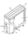
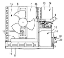
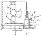
図1乃至図5は、本発明のヒートポンプ給湯室外機の実施の形態1を示す図である。図1はヒートポンプ給湯室外機の正面側斜視図であり、図2はヒートポンプ給湯室外機の後面側斜視図であり、図3はヒートポンプ給湯室外機の内部構造を示す正面図であり、図4は図3における機械室の内部構造の詳細を示す正面図であり、図5はベースおよび水冷媒熱交換器の斜視図である。
Embodiment 1 FIG.
[Configuration of this embodiment]
1 to 5 are views showing Embodiment 1 of the heat pump hot water supply outdoor unit of the present invention. 1 is a front perspective view of a heat pump hot water outdoor unit, FIG. 2 is a rear perspective view of the heat pump hot water outdoor unit, FIG. 3 is a front view showing the internal structure of the heat pump hot water outdoor unit, and FIG. FIG. 5 is a front view showing details of the internal structure of the machine room in FIG. 3, and FIG. 5 is a perspective view of the base and the water-refrigerant heat exchanger.
まず、図1乃至図5を参照して、本実施形態のヒートポンプ給湯室外機の全体構成について説明する。尚、図1中では、左下が前方、右上が後方であり、また、図2中では、左上が前方、右下が後方である。図1乃至図3に示すように、本実施形態のヒートポンプ給湯室外機の外郭は、底部(基部)を構成するベース17と、筐体の前面部18、後面部19、上面部20、右側面部21および左側面部22で構成されている。空気熱交換器7、および後述する第2の空気熱交換器25の設置部以外は、上記筐体で覆われている。筐体は、通常、板金材から成形される。ヒートポンプ給湯室外機の内部は、仕切板16が設けられ、この仕切板16により、前面から見て右側の機械室14と左側の送風機室15とに区画されている。
First, with reference to FIG. 1 thru | or FIG. 5, the whole structure of the heat pump hot-water supply outdoor unit of this embodiment is demonstrated. In FIG. 1, the lower left is the front and the upper right is the rear, and in FIG. 2, the upper left is the front and the lower right is the rear. As shown in FIGS. 1 to 3, the exterior of the heat pump hot water supply outdoor unit of the present embodiment includes a
図4では図示を省略しているものもあるが、機械室14内には、冷媒を圧縮するための圧縮機2、冷媒を減圧するための膨張弁(図示せず)、これらを接続する吸入管4や吐出管5等の冷媒配管、その他の冷媒回路部品が組み込まれている。圧縮機2の本体2aの内部には、冷媒の圧縮動作を行う圧縮部(図示せず)と、圧縮部と接続され圧縮部を駆動するモータ(図示せず)が組み込まれ、外部から供給される電力によりモータおよび圧縮部が所定の回転数で駆動するようになっている。また、圧縮機2の本体2a内に吸入する冷媒の脈動音を消音するための吸入マフラ2cが本体2aの側面下部に取り付けられている。また、圧縮機2の本体2aを固定するための脚部材2bが本体2aの下部に溶接にて取り付けられており、脚部材2bには3〜4個の防振マウント3が取り付けられている。防振マウント3は、概略円筒形のゴムあるいは金属コイルの成形品で、中にボルトが挿入できる孔を設けた構造となっており、ゴムあるいは金属コイルの弾性特性により、所定のバネ定数と減衰率を有している。防振マウント3は、ベース17の上面に設置され、圧縮機2を弾性的に支持している。また、冷媒を吸入するための吸入管4が圧縮機2の吸入マフラ2cの上部に取り付けられ、冷媒を圧縮機2の本体2a内部で圧縮した後に吐出するための吐出管5が圧縮機2の本体2a上部に取り付けられている。膨張弁は、本体外側面にコイル組み込み部材が取り付けられ、コイルに外部から通電することにより発生する電磁作用により、内部の流路抵抗調節部を稼動させて冷媒の流路抵抗を調節し、膨張弁の上流側高圧と下流側低圧の冷媒を所定の圧力に調節するようになっている。
Although there are some illustrations omitted in FIG. 4, a
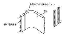
送風機室15内には、送風機6と、これに隣接する空気熱交換器7とが組み込まれている。送風機室15内は、風路確保のため大きな空間を有している。送風機6は、3枚の翼型のプロペラと、このプロペラを回転駆動させるモータとが組み合わされており、外部から供給される電力によりモータとプロペラが所定の回転数で回転するようになっている。空気熱交換器7は、アルミ薄板のフィンが多数密着した長い冷媒配管が略L字平板状に曲げ成形されており、冷媒配管内の冷媒とフィン周辺の空気とで熱交換が行われるようになっており、送風機6により各フィン間を流れて通過する空気の風量が増やされて調節され、熱交換の量が増やされて調節されている。
A blower 6 and an
図5に示すように、送風機室15内の下部のベース17の上面には、水冷媒熱交換器8が設置されている。水冷媒熱交換器8は、外形が前方から見て左右に長い略直方体形状の発泡材の収納容器12に収納され、十分な防振効果の有る防振材の介在無しに、送風機室15内の送風機6の下方に位置するベース17の上面に設置されている。水冷媒熱交換器8を収納した収納容器12は、ベース17に取り付けられた板金材の収納囲部材10に囲まれ、発泡材の収納容器蓋13により上側を覆われ、その上から更に板金材の収納蓋部材11により上面を覆われている。水冷媒熱交換器8は、長い水配管に長い冷媒配管が長手方向に密着し、略直方体形状の収納容器12に収納可能なように曲げ成形されており、冷媒配管内の冷媒と水配管内の水とで熱交換が行われるようになっている。
As shown in FIG. 5, a water-refrigerant heat exchanger 8 is installed on the upper surface of the
圧縮機2は、吐出管5を介して水冷媒熱交換器8の冷媒入口部と接続され、水冷媒熱交換器8の冷媒出口部は、冷媒配管を介して機械室14内の膨張弁の入口部と接続されている。膨張弁の出口部は、別の冷媒配管を介して空気熱交換器7の冷媒入口部と接続されている。空気熱交換器7の冷媒出口部は、吸入管4を介して圧縮機2と接続されている。また、冷媒配管の途中にはその他の冷媒回路部品が取り付けられている場合もある。このように構成された冷媒回路の密閉空間内に所定の量の冷媒が封入されており、通常CO2冷媒が使用されている。
The
図3において、図示省略しているが、機械室14内には、水冷媒熱交換器8の水入口部に接続された内部水配管A、水冷媒熱交換器8の給湯出口部と接続された内部水配管B、その他の水回路部品が組み込まれている。内部水配管Aはベース17右部と筐体の右側面部21下部に取り付けられた水入口バルブ29に接続され、内部水配管Bはベース17右部と筐体の右側面部21下部に取り付けられた給湯出口バルブ30に取り付けられ、筐体の右側面部21に、水入口バルブ29が上部、給湯出口バルブ30が下部に併設して配置されている。また、水入口バルブ29と給湯出口バルブ30を保護するため、サービスパネル23が右側面部21に取り付けられている。
Although not shown in FIG. 3, the
このようなヒートポンプ給湯室外機は、数百リットル程度の容量を有する貯湯タンクとこの貯湯タンク内の水を送る水ポンプとが組み込まれた貯湯装置(図示せず)に対し、外部水配管A(図示せず)、外部水配管B(図示せず)、電気配線(図示せず)を介して接続して使用される。水ポンプの入口部は貯湯タンク下部に接続され、外部水配管Aは水ポンプの出口部に接続されており、外部水配管Bが貯湯タンク上部に接続されている。外部水配管Aの貯湯タンク接続側と反対側はヒートポンプ給湯室外機のサービスパネル23内の水入口バルブ29と接続され、外部水配管Bの貯湯タンク接続側と反対側はヒートポンプ給湯室外機のサービスパネル23内の給湯出口バルブ30と接続されている。このように、ヒートポンプ給湯室外機と貯湯装置とで給湯回路が構成されている。
Such a heat pump hot water supply outdoor unit has an external water pipe A (not shown) for a hot water storage device (not shown) in which a hot water storage tank having a capacity of about several hundred liters and a water pump for sending water in the hot water storage tank are incorporated. (Not shown), an external water pipe B (not shown), and electrical wiring (not shown). The inlet of the water pump is connected to the lower part of the hot water storage tank, the external water pipe A is connected to the outlet of the water pump, and the outer water pipe B is connected to the upper part of the hot water storage tank. The side of the external water pipe A opposite to the hot water tank connecting side is connected to the
(本実施の形態の特徴的構成)
次に、本実施の形態のヒートポンプ給湯室外機の特徴的構成について説明する。図3に示すように、機械室14の上方には、圧縮機2、膨張弁、送風機6等を駆動制御するインバータ電源等の電気部品を収納した電気品箱9が設置されている。インバータ電源は、圧縮機2のモータの回転数を、例えば数十rps(Hz)〜百rps(Hz)程度の所定の回転数に変化させ、また、膨張弁の開度を所定の量に変化させ、また、送風機6の回転数を、例えば数百rpm〜千rpm程度の所定の回転数に変化させるよう制御される。電気品箱9の右部には、外部電気配線を接続する端子台9aがあり、この端子台9aを保護するため、サービスパネル23が筐体の右側面部21に取り付けられている。
(Characteristic configuration of the present embodiment)
Next, a characteristic configuration of the heat pump hot water supply outdoor unit of the present embodiment will be described. As shown in FIG. 3, an electrical component box 9 that stores electrical components such as an inverter power source that drives and controls the
ここで、本実施の形態のインバータ電源等の電子部品には、窒化珪素(SiC)素子等のワイドバンドギャップ半導体素子が用いられている。尚、ワイドバンドギャップ半導体としてはSiC素子に限らず、例えば、窒化ガリウム(GaN)系の材料やダイヤモンドを用いることとしてもよい。このようなワイドバンドギャップ半導体によって形成された半導体素子は耐電圧性が高く、また、許容電流密度も高い。このため、これらの半導体素子の小型化が可能であり、小型化されたワイドバンドギャップ半導体素子を本装置の電子部品として用いることにより、電気品箱9の小型化が可能となる。 Here, a wide band gap semiconductor element such as a silicon nitride (SiC) element is used for an electronic component such as an inverter power source of the present embodiment. The wide band gap semiconductor is not limited to the SiC element, and for example, a gallium nitride (GaN) -based material or diamond may be used. A semiconductor element formed of such a wide band gap semiconductor has a high voltage resistance and a high allowable current density. For this reason, these semiconductor elements can be miniaturized, and the electrical component box 9 can be miniaturized by using the miniaturized wide band gap semiconductor element as an electronic component of this apparatus.
また、ワイドバンドギャップ半導体素子は耐熱性が高い特徴を有している。このため、電気品箱9に通常設置されるヒートシンクのフィンを大幅に小型化ないしは省略することができるので、電気品箱9の更なる小型化が可能となる。 In addition, the wide band gap semiconductor element has a feature of high heat resistance. For this reason, the fins of the heat sink normally installed in the electrical component box 9 can be greatly downsized or omitted, so that the electrical component box 9 can be further miniaturized.
更に、ワイドバンドギャップ半導体素子は電力損失が低いという特徴を有している。このため、半導体素子の高効率化が可能であり、延いては半導体モジュールの高効率化が可能となる。 Furthermore, the wide band gap semiconductor element has a feature of low power loss. For this reason, it is possible to increase the efficiency of the semiconductor element, and further increase the efficiency of the semiconductor module.
尚、スイッチング素子やダイオード素子等の全ての半導体素子がワイドバンドギャップ半導体によって形成されていることが好ましいが、少なくとも一部の半導体素子がワイドバンドギャップ半導体素子によって形成されていれば、この実施の形態に記載されている効果を得ることができる。 It is preferable that all semiconductor elements such as switching elements and diode elements are formed of wide band gap semiconductors. However, if at least some of the semiconductor elements are formed of wide band gap semiconductor elements, The effect described in the form can be obtained.
このように、ワイドバンドギャップ半導体によって形成された電子部品を用いることにより、電気品箱9が従来のものと比して小型化される。また、上述したとおり、電気品箱9に通常設けられる放熱部品を小型化乃至省略することが可能となるため、例えば電気品箱9から送風機室15側へ突出して部品26の突出量を有効に抑制することができる。したがって、本実施の形態の室外機の構成によれば、送風機6との干渉を避けるために従来室外機の最上部付近に配置されていた電気品箱9をより下方へ配置することが可能となる。
As described above, by using the electronic component formed of the wide band gap semiconductor, the electrical component box 9 is reduced in size as compared with the conventional one. In addition, as described above, since it is possible to reduce or omit the heat dissipating component normally provided in the electrical component box 9, for example, it projects from the electrical component box 9 to the blower chamber 15 side to effectively increase the projection amount of the
電気品箱9をより下方に配置すると、仕切板16の高さをより低くすることができるので、該電気品箱9の上方に送風機室15と連通した空間(以下、「電気品箱上方室24」と称する)を形成することができる。そこで、本実施の形態のヒートポンプ給湯装置では、この電気品箱上方室24に第2の空気熱交換器25を増設することとしている。図6は、第2の空気熱交換器の形状を説明するための図である。この図に示すとおり、第2の空気熱交換器25の形状としては、後面部19から右側面部21に沿ったL字型の形状とすることができる。これにより、限られた電気品箱上方室24の空間内で有効にスペースを活用することができるので、空気と冷媒との熱交換効率を有効に高めることができる。これにより、室外機の外形寸法を拡大することなく、システムのエネルギ効率を有効に高めることが可能となる。
If the electrical component box 9 is arranged at a lower position, the height of the
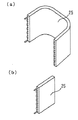
尚、第2の空気熱交換器25の形状は、L字形状に限らず、種々の形状を採用することもできる。図7は、第2の空気熱交換器の形状の変形例を示す図である。この図中の(A)に示すとおり、第2の空気熱交換器25の形状として、前面部18、後面部19または右側面部21に沿って略平面上の形状とすることができる。これにより、第2の空気熱交換器25の製造コストの抑制を図ることができる。また、第2の空気熱交換器25の形状としては、この図中の(B)に示すとおり、後面部19、右側面部21、および前面部18に沿ったU字形状としてもよい。これにより空気と冷媒との熱交換効率を最大限に高めることが可能となる。
The shape of the second
実施の形態2.
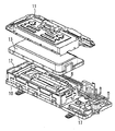
次に、図8および9を参照して、本発明の実施の形態2について説明する。本実施の形態2では、上述した実施の形態との相違点を中心に説明し、同一部分または相当部分は同一符号を付し説明を省略する。図8は本実施の形態2の室外機のベースおよび水冷媒熱交換器の斜視図であり、図9は本実施の形態2の水冷媒熱交換器の近傍を拡大して示す平面図である。
Next, a second embodiment of the present invention will be described with reference to FIGS. In this
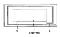
図8および図9に示すように、本実施形態では、水冷媒熱交換器8が収納されている収納箱12内に第2の電気品箱27を収納した点に特徴がある。第2の電気品箱27の内部には、電気品箱9の内部に収納されていたワイドバンドギャップ半導体等の電子部品の一部または全部が収納されている。
As shown in FIGS. 8 and 9, the present embodiment is characterized in that the second
このような構成のヒートポンプ給湯室外機の構成によれば、圧縮機2の上方に配置されていた電気品箱9を更に小型化或いは完全に移設することができるので、電気品箱上方室24の空間を更に拡大させることが可能となる。これにより、第2の空気熱交換器25を更に大型化して更なるシステム効率の向上を図ることができる。また、電気品箱上方室24を拡大することで、該電気品箱上方室24内への空気の流通をより円滑にすることができるので、第2の空気熱交換器25の熱交換効率を有効に高めることが可能となる。
According to the configuration of the heat pump hot water supply outdoor unit having such a configuration, the electrical component box 9 disposed above the
2 圧縮機
2a 本体
2b 脚部材
2c 吸入マフラ
3 防振マウント
4 吸入管
5 吐出管
6 送風機
7 空気熱交換器
8 水冷媒熱交換器
9 電気品箱
10 収納囲部材
11 収納蓋部材
12 収納容器
13 収納容器蓋
14 機械室
15 送風機室
16 仕切板
17 ベース
18 筐体の前面部
19 筐体の後面部
20 筐体の上面部
21 筐体の右側面部
22 筐体の左側面部
23 サービスパネル
24 電気品箱上方室
25 第2の空気熱交換器
27 第2の電気品箱
2
Claims (7)
冷媒を圧縮する圧縮機が配置された機械室と、
冷媒と空気とを熱交換させる空気熱交換器と、送風機と、が配置された送風機室と、
前記圧縮機の上方に配置され、前記ヒートポンプ回路を駆動させるための電子部品を収納する電気品箱と、
前記電気品箱の上方に形成され、前記送風機室と連通する電気品箱上方室と、
をその内部に備え、
前記電気品箱内の電子部品は、ワイドバンドギャップ半導体によって形成された電子部品を含み、
前記電気品箱上方室に第2の空気熱交換器を備えるヒートポンプ給湯室外機。 A heat pump hot water outdoor unit that heats water by a heat pump circuit,
A machine room in which a compressor for compressing refrigerant is disposed;
An air heat exchanger for exchanging heat between the refrigerant and the air, and a blower chamber in which a blower is disposed;
An electrical component box that is disposed above the compressor and stores electronic components for driving the heat pump circuit; and
An electrical component box upper chamber formed above the electrical component box and communicating with the blower chamber;
With its inside,
The electronic component in the electrical component box includes an electronic component formed of a wide band gap semiconductor,
A heat pump hot water supply outdoor unit comprising a second air heat exchanger in the upper compartment of the electrical component box.
前記仕切板は、前記送風機室と前記電気品箱上方室との連通が確保される高さに形成されている請求項1記載のヒートポンプ給湯室外機。 A partition plate that partitions the machine room and the blower room;
2. The heat pump hot water supply outdoor unit according to claim 1, wherein the partition plate is formed at a height that allows communication between the blower chamber and the upper compartment of the electrical component box.
前記水冷媒熱交換器を収納する収納箱と、
前記収納箱内に配置された第2の電気品箱と、を更に備え、
前記第2の電気品箱の内部には、前記電気品箱内の電子部品の少なくとも一部が移設されている請求項1乃至6の何れか1項記載のヒートポンプ給湯室外機。 A water-refrigerant heat exchanger that exchanges heat between water and the refrigerant;
A storage box for storing the water refrigerant heat exchanger;
A second electrical component box disposed in the storage box,
The heat pump hot water supply outdoor unit according to any one of claims 1 to 6, wherein at least a part of the electronic components in the electrical component box is relocated inside the second electrical component box.
Priority Applications (1)
| Application Number | Priority Date | Filing Date | Title |
|---|---|---|---|
| JP2011004124A JP2012145274A (en) | 2011-01-12 | 2011-01-12 | Heat pump hot water supply outdoor unit |
Applications Claiming Priority (1)
| Application Number | Priority Date | Filing Date | Title |
|---|---|---|---|
| JP2011004124A JP2012145274A (en) | 2011-01-12 | 2011-01-12 | Heat pump hot water supply outdoor unit |
Publications (2)
| Publication Number | Publication Date |
|---|---|
| JP2012145274A true JP2012145274A (en) | 2012-08-02 |
| JP2012145274A5 JP2012145274A5 (en) | 2013-08-01 |
Family
ID=46789006
Family Applications (1)
| Application Number | Title | Priority Date | Filing Date |
|---|---|---|---|
| JP2011004124A Pending JP2012145274A (en) | 2011-01-12 | 2011-01-12 | Heat pump hot water supply outdoor unit |
Country Status (1)
| Country | Link |
|---|---|
| JP (1) | JP2012145274A (en) |
Cited By (4)
| Publication number | Priority date | Publication date | Assignee | Title |
|---|---|---|---|---|
| JP2014167367A (en) * | 2013-02-28 | 2014-09-11 | Mitsubishi Electric Corp | Heat pump hot water supply outdoor unit and heat pump hot water supply system |
| JP2015172473A (en) * | 2014-03-12 | 2015-10-01 | 三菱電機株式会社 | Heat pump hot water supply outdoor unit |
| WO2017006389A1 (en) * | 2015-07-03 | 2017-01-12 | 三菱電機株式会社 | Heat pump device |
| WO2020003511A1 (en) * | 2018-06-29 | 2020-01-02 | 三菱電機株式会社 | Heat pump device |
Citations (10)
| Publication number | Priority date | Publication date | Assignee | Title |
|---|---|---|---|---|
| JPH029728U (en) * | 1988-06-30 | 1990-01-22 | ||
| JPH0498026A (en) * | 1990-08-16 | 1992-03-30 | Mitsubishi Electric Corp | Outdoor unit of air conditioner |
| JP2003279076A (en) * | 2002-03-20 | 2003-10-02 | Sanyo Electric Co Ltd | Outdoor unit of air-conditioner |
| JP2008057852A (en) * | 2006-08-31 | 2008-03-13 | Daikin Ind Ltd | Refrigerating device |
| JP2008061372A (en) * | 2006-08-31 | 2008-03-13 | Daikin Ind Ltd | Refrigerating device |
| JP2008057851A (en) * | 2006-08-31 | 2008-03-13 | Daikin Ind Ltd | Refrigerating device |
| JP2008304115A (en) * | 2007-06-07 | 2008-12-18 | Sharp Corp | Heat pump unit and heat pump type water heater |
| JP4280114B2 (en) * | 2003-06-09 | 2009-06-17 | 東芝キヤリア株式会社 | Air conditioner |
| JP2010147334A (en) * | 2008-12-19 | 2010-07-01 | Daikin Ind Ltd | Refrigerating apparatus |
| JP2010261601A (en) * | 2009-04-30 | 2010-11-18 | Panasonic Corp | Outdoor unit of air conditioner |
-
2011
- 2011-01-12 JP JP2011004124A patent/JP2012145274A/en active Pending
Patent Citations (10)
| Publication number | Priority date | Publication date | Assignee | Title |
|---|---|---|---|---|
| JPH029728U (en) * | 1988-06-30 | 1990-01-22 | ||
| JPH0498026A (en) * | 1990-08-16 | 1992-03-30 | Mitsubishi Electric Corp | Outdoor unit of air conditioner |
| JP2003279076A (en) * | 2002-03-20 | 2003-10-02 | Sanyo Electric Co Ltd | Outdoor unit of air-conditioner |
| JP4280114B2 (en) * | 2003-06-09 | 2009-06-17 | 東芝キヤリア株式会社 | Air conditioner |
| JP2008057852A (en) * | 2006-08-31 | 2008-03-13 | Daikin Ind Ltd | Refrigerating device |
| JP2008061372A (en) * | 2006-08-31 | 2008-03-13 | Daikin Ind Ltd | Refrigerating device |
| JP2008057851A (en) * | 2006-08-31 | 2008-03-13 | Daikin Ind Ltd | Refrigerating device |
| JP2008304115A (en) * | 2007-06-07 | 2008-12-18 | Sharp Corp | Heat pump unit and heat pump type water heater |
| JP2010147334A (en) * | 2008-12-19 | 2010-07-01 | Daikin Ind Ltd | Refrigerating apparatus |
| JP2010261601A (en) * | 2009-04-30 | 2010-11-18 | Panasonic Corp | Outdoor unit of air conditioner |
Cited By (7)
| Publication number | Priority date | Publication date | Assignee | Title |
|---|---|---|---|---|
| JP2014167367A (en) * | 2013-02-28 | 2014-09-11 | Mitsubishi Electric Corp | Heat pump hot water supply outdoor unit and heat pump hot water supply system |
| JP2015172473A (en) * | 2014-03-12 | 2015-10-01 | 三菱電機株式会社 | Heat pump hot water supply outdoor unit |
| WO2017006389A1 (en) * | 2015-07-03 | 2017-01-12 | 三菱電機株式会社 | Heat pump device |
| JPWO2017006389A1 (en) * | 2015-07-03 | 2017-09-14 | 三菱電機株式会社 | Heat pump equipment |
| WO2020003511A1 (en) * | 2018-06-29 | 2020-01-02 | 三菱電機株式会社 | Heat pump device |
| EP3816535A4 (en) * | 2018-06-29 | 2021-06-23 | Mitsubishi Electric Corporation | Heat pump device |
| JPWO2020003511A1 (en) * | 2018-06-29 | 2021-06-24 | 三菱電機株式会社 | Heat pump device |
Similar Documents
| Publication | Publication Date | Title |
|---|---|---|
| JP5287614B2 (en) | Heat pump outdoor unit | |
| JPWO2016157305A1 (en) | Heat pump hot water outdoor unit and water heater | |
| JP6070273B2 (en) | Heat pump hot water outdoor unit and heat pump hot water system | |
| JP2012145274A (en) | Heat pump hot water supply outdoor unit | |
| KR20070086899A (en) | Outdoor unit of air conditioner | |
| JP5640938B2 (en) | Heat pump water heater outdoor unit | |
| JP2006214632A (en) | Outdoor unit of air conditioner | |
| JP2006214633A (en) | Outdoor unit of air conditioner | |
| JP2014167367A5 (en) | ||
| JP6562685B2 (en) | Harmonic suppression device and air conditioner using the same | |
| JP5609832B2 (en) | Heat pump outdoor unit | |
| JP6841350B2 (en) | Heat pump hot water supply outdoor unit | |
| JP5348105B2 (en) | Heat pump water heater outdoor unit | |
| JP5754423B2 (en) | Heat pump water heater outdoor unit | |
| JP5423509B2 (en) | Heat pump water heater | |
| JP5880123B2 (en) | Heat pump outdoor unit | |
| JP2013164048A (en) | Electric compressor | |
| JP5625966B2 (en) | Heat pump water heater outdoor unit | |
| JP5630427B2 (en) | Heat pump water heater outdoor unit | |
| JP6669306B2 (en) | Heat pump equipment | |
| JP2014240713A (en) | Outdoor unit for air conditioner | |
| JP6156210B2 (en) | Heat pump water heater outdoor unit | |
| JP2017048960A (en) | Outdoor unit of air conditioner and air conditioner | |
| JP6943346B2 (en) | Heat pump device | |
| CN219515188U (en) | Heating device and refrigerator with same |
Legal Events
| Date | Code | Title | Description |
|---|---|---|---|
| A521 | Written amendment |
Free format text: JAPANESE INTERMEDIATE CODE: A523 Effective date: 20130618 |
|
| A621 | Written request for application examination |
Free format text: JAPANESE INTERMEDIATE CODE: A621 Effective date: 20130618 |
|
| A977 | Report on retrieval |
Free format text: JAPANESE INTERMEDIATE CODE: A971007 Effective date: 20140326 |
|
| A131 | Notification of reasons for refusal |
Free format text: JAPANESE INTERMEDIATE CODE: A131 Effective date: 20140401 |
|
| A521 | Written amendment |
Free format text: JAPANESE INTERMEDIATE CODE: A523 Effective date: 20140508 |
|
| A02 | Decision of refusal |
Free format text: JAPANESE INTERMEDIATE CODE: A02 Effective date: 20140924 |