JP5880123B2 - Heat pump outdoor unit - Google Patents
Heat pump outdoor unit Download PDFInfo
- Publication number
- JP5880123B2 JP5880123B2 JP2012036030A JP2012036030A JP5880123B2 JP 5880123 B2 JP5880123 B2 JP 5880123B2 JP 2012036030 A JP2012036030 A JP 2012036030A JP 2012036030 A JP2012036030 A JP 2012036030A JP 5880123 B2 JP5880123 B2 JP 5880123B2
- Authority
- JP
- Japan
- Prior art keywords
- refrigerant
- water
- hot water
- outdoor unit
- heat pump
- Prior art date
- Legal status (The legal status is an assumption and is not a legal conclusion. Google has not performed a legal analysis and makes no representation as to the accuracy of the status listed.)
- Active
Links
- XLYOFNOQVPJJNP-UHFFFAOYSA-N water Substances O XLYOFNOQVPJJNP-UHFFFAOYSA-N 0.000 claims description 176
- 239000003507 refrigerant Substances 0.000 claims description 128
- 239000007788 liquid Substances 0.000 claims description 7
- 239000013013 elastic material Substances 0.000 claims description 2
- 239000000463 material Substances 0.000 claims description 2
- 230000006835 compression Effects 0.000 description 9
- 238000007906 compression Methods 0.000 description 9
- 238000009434 installation Methods 0.000 description 7
- 238000005192 partition Methods 0.000 description 6
- 238000004519 manufacturing process Methods 0.000 description 5
- 230000005540 biological transmission Effects 0.000 description 4
- 238000009835 boiling Methods 0.000 description 3
- 239000006261 foam material Substances 0.000 description 3
- 229910052751 metal Inorganic materials 0.000 description 3
- 239000002184 metal Substances 0.000 description 3
- 230000000694 effects Effects 0.000 description 2
- 238000009429 electrical wiring Methods 0.000 description 2
- 239000007769 metal material Substances 0.000 description 2
- 238000000034 method Methods 0.000 description 2
- 230000003014 reinforcing effect Effects 0.000 description 2
- 238000011144 upstream manufacturing Methods 0.000 description 2
- 229910052782 aluminium Inorganic materials 0.000 description 1
- XAGFODPZIPBFFR-UHFFFAOYSA-N aluminium Chemical compound [Al] XAGFODPZIPBFFR-UHFFFAOYSA-N 0.000 description 1
- 230000002528 anti-freeze Effects 0.000 description 1
- 230000002238 attenuated effect Effects 0.000 description 1
- 238000005452 bending Methods 0.000 description 1
- 239000012267 brine Substances 0.000 description 1
- 239000000470 constituent Substances 0.000 description 1
- 239000002826 coolant Substances 0.000 description 1
- 238000007599 discharging Methods 0.000 description 1
- 238000009413 insulation Methods 0.000 description 1
- NJPPVKZQTLUDBO-UHFFFAOYSA-N novaluron Chemical compound C1=C(Cl)C(OC(F)(F)C(OC(F)(F)F)F)=CC=C1NC(=O)NC(=O)C1=C(F)C=CC=C1F NJPPVKZQTLUDBO-UHFFFAOYSA-N 0.000 description 1
- HPALAKNZSZLMCH-UHFFFAOYSA-M sodium;chloride;hydrate Chemical compound O.[Na+].[Cl-] HPALAKNZSZLMCH-UHFFFAOYSA-M 0.000 description 1
Images


Description
本発明は、ヒートポンプ室外機に関する。 The present invention relates to a heat pump outdoor unit.
空気の熱を吸収して湯を沸かすことのできる、エネルギー効率に優れたヒートポンプ式給湯システムが広く用いられている。ヒートポンプ式給湯システムの構成要素であるヒートポンプ給湯室外機は、空気の熱を冷媒に吸熱させる空気冷媒熱交換器、この空気冷媒熱交換器に送風する送風機、冷媒を圧縮する圧縮機、冷媒の熱によって水を加熱する水冷媒熱交換器などを搭載しており、一般には次のような構造となっている。ヒートポンプ給湯室外機には、重量が大きく横に長い形状の水冷媒熱交換器が、発泡材等の収納箱に収納されて、ベース上面に設置されている。また、圧縮機がゴム部材や金属スプリング部材等の防振マウントを介してベース上面に設置されている。圧縮機と水冷媒熱交換器とは、冷媒配管を介して接続され、圧縮機と水冷媒熱交換器とがベース上面に横に並べて設置されている。また、ヒートポンプ給湯室外機の筐体の側部には、外部と湯水をやり取りするための外部水配管が接続される水入口バルブおよび給湯出口バルブが設けられている。水入口バルブおよび給湯出口バルブは、筐体の内部において、入水用および出湯用の2本の内部水配管を介して水冷媒熱交換器と接続されている。水入口バルブおよび給湯出口バルブを支持するバルブベッドは、筐体の側面に固定されている(例えば、特許文献1参照)。 An energy efficient heat pump type hot water supply system that can boil hot water by absorbing the heat of air is widely used. The heat pump hot water outdoor unit that is a component of the heat pump hot water supply system includes an air refrigerant heat exchanger that absorbs heat of air into the refrigerant, a blower that blows air to the air refrigerant heat exchanger, a compressor that compresses the refrigerant, and the heat of the refrigerant A water-refrigerant heat exchanger that heats the water is mounted, and generally has the following structure. In the heat pump hot water supply outdoor unit, a water-refrigerant heat exchanger having a large weight and a long side shape is housed in a storage box such as a foam material and installed on the upper surface of the base. A compressor is installed on the upper surface of the base via a vibration-proof mount such as a rubber member or a metal spring member. The compressor and the water refrigerant heat exchanger are connected via a refrigerant pipe, and the compressor and the water refrigerant heat exchanger are installed side by side on the upper surface of the base. Further, a water inlet valve and a hot water outlet valve to which an external water pipe for exchanging hot water with the outside is connected are provided on the side of the casing of the heat pump hot water outdoor unit. The water inlet valve and the hot water outlet valve are connected to the water / refrigerant heat exchanger through two internal water pipes for incoming and outgoing hot water inside the housing. The valve bed that supports the water inlet valve and the hot water outlet valve is fixed to the side surface of the housing (see, for example, Patent Document 1).
上述したような従来のヒートポンプ給湯室外機では、運転中に圧縮機の振動が冷媒配管から水冷媒熱交換器に伝達し、水冷媒熱交換器の振動は内部水配管を介してバルブベッドに伝達し、バルブベッドの振動が筐体側部から筐体各部に伝達する。このため、ヒートポンプ給湯室外機の筐体各部の振動が増加し、筐体各部から放射される騒音や低周波音が増加し易くなっている。この対策として、バルブベッドを筐体側部に取り付ける際に緩衝部材を介在させる等、振動伝達を抑制する方法があるが、ヒートポンプ給湯室外機の運搬時や設置使用時等における、バルブベッドの筐体側部に対する保持強度が不足する等の問題がある。また、別の方法としては、振動、騒音および低周波音の増加を抑制するために筐体各部への防振部材の貼り付け、筐体各部の板厚増加、筐体各部への補強部材取付け等の方法があるが、製造コストが著しく増加するという問題がある。 In the conventional heat pump hot water supply outdoor unit as described above, the vibration of the compressor is transmitted from the refrigerant pipe to the water refrigerant heat exchanger during operation, and the vibration of the water refrigerant heat exchanger is transmitted to the valve bed via the internal water pipe. The vibration of the valve bed is transmitted from the side of the casing to each part of the casing. For this reason, vibration of each part of the housing of the heat pump hot water supply outdoor unit increases, and noise and low-frequency sound radiated from each part of the housing are likely to increase. As a countermeasure, there is a method of suppressing vibration transmission, such as interposing a buffer member when attaching the valve bed to the side of the casing, but the casing side of the valve bed when transporting or installing the heat pump hot water outdoor unit etc. There is a problem that the holding strength to the part is insufficient. In addition, as another method, in order to suppress an increase in vibration, noise, and low frequency sound, a vibration isolating member is attached to each part of the casing, a thickness of each part of the casing is increased, and a reinforcing member is attached to each part of the casing. However, there is a problem that the manufacturing cost is remarkably increased.
本発明は、上述のような課題を解決するためになされたもので、製造コストの増加を抑制しながら、筐体各部の振動を抑制し、筐体各部から放射される騒音や低周波音を抑制することができるヒートポンプ室外機を提供することを目的とする。 The present invention has been made in order to solve the above-described problems. While suppressing an increase in manufacturing cost, the present invention suppresses vibration of each part of the casing and reduces noise and low-frequency sound radiated from each part of the casing. It aims at providing the heat pump outdoor unit which can be suppressed.
本発明に係るヒートポンプ室外機は、封入した冷媒が循環する冷媒回路と、冷媒と水または液状熱媒体との熱交換を行う水冷媒熱交換器と、冷媒回路および水冷媒熱交換器を収容する筐体と、水または液状熱媒体が通る外部の配管である外部水配管を接続可能な接続バルブと、接続バルブを支持するバルブ支持部材と、筐体の内部で水冷媒熱交換器と接続バルブとの間を接続し、水または液状熱媒体が通る内部水配管と、筐体の底部に設けられ、筐体を支持する脚部材と、を備え、バルブ支持部材と脚部材とを連結する連結部を含み、連結部は、脚部材から略水平に延びてバルブ支持部材の下端に繋がっているものである。
A heat pump outdoor unit according to the present invention accommodates a refrigerant circuit in which enclosed refrigerant circulates, a water refrigerant heat exchanger that performs heat exchange between the refrigerant and water or a liquid heat medium, a refrigerant circuit, and a water refrigerant heat exchanger. A connection valve that can connect a housing and an external water pipe that is an external pipe through which water or a liquid heat medium passes, a valve support member that supports the connection valve, a water refrigerant heat exchanger and a connection valve inside the housing And an internal water pipe through which water or a liquid heat medium passes, and a leg member that is provided at the bottom of the casing and supports the casing, and connects the valve support member and the leg member. The connecting portion extends substantially horizontally from the leg member and is connected to the lower end of the valve support member.
本発明によれば、製造コストの増加を抑制しながら、筐体各部の振動を抑制し、筐体各部から放射される騒音や低周波音を抑制することが可能となる。 ADVANTAGE OF THE INVENTION According to this invention, it becomes possible to suppress the vibration of each part of a housing | casing, suppressing the increase in manufacturing cost, and to suppress the noise and low frequency sound radiated | emitted from each part of a housing | casing.
以下、図面を参照して本発明の実施の形態について説明する。なお、各図において共通する要素には、同一の符号を付して、重複する説明を省略する。 Embodiments of the present invention will be described below with reference to the drawings. In addition, the same code | symbol is attached | subjected to the element which is common in each figure, and the overlapping description is abbreviate | omitted.
実施の形態1.
図1は、本発明の実施の形態1のヒートポンプ給湯室外機の分解斜視図である。なお、図1中では、左下が前方、右上が後方である。図2は、本発明の実施の形態1のヒートポンプ給湯室外機のベースに対する水冷媒熱交換器の設置状態を示す分解斜視図である。図3は、本発明の実施の形態1のヒートポンプ給湯室外機の内部構造を示す正面図および要部拡大図である。図4は、本発明の実施の形態1のヒートポンプ給湯室外機の底面図である。
FIG. 1 is an exploded perspective view of a heat pump hot water supply outdoor unit according to Embodiment 1 of the present invention. In FIG. 1, the lower left is the front and the upper right is the rear. FIG. 2 is an exploded perspective view showing an installation state of the water refrigerant heat exchanger with respect to the base of the heat pump hot water supply outdoor unit according to
まず、本実施形態のヒートポンプ給湯室外機の全体構成について説明する。図1に示すように、本実施形態のヒートポンプ給湯室外機1は、その構成機器を収容する筐体を有している。この筐体は、底部を構成するベース17と、前面および左側面を覆う前面左側面部18aと、後面および右側面を覆う後面右側面部18bと、上面を覆う上面部18cとを組み合わせて構成されている。上記筐体は、主に板金材等で構成される。ヒートポンプ給湯室外機1は、空気冷媒熱交換器7の設置部以外は、上記筐体で覆われている。上記筐体の内部には、仕切板16が設けられ、この仕切板16により、前面から見て右側の機械室14と、左側の送風機室15とに筐体内部が区画されている。機械室14の上方と送風機室15の上方の一部には、圧縮機2、膨張弁、送風機6等を駆動制御するインバータ電源等の電気部品を収納した電気部品収納箱9が組み込まれている。電気部品収納箱9の右部には、外部電気配線を接続する端子台9aが設けられている。この端子台9aを保護するため、サービスパネル24が筐体の後面右側面部18bの右側面部に取り付けられている。
First, the whole structure of the heat pump hot water supply outdoor unit of this embodiment is demonstrated. As shown in FIG. 1, the heat pump hot water supply
図2に示すように、水冷媒熱交換器8は、断熱性を有する発泡材で構成された収納容器12に収納された状態で、ベース17の上面に設置されている。収納容器12は、ベース17に取り付けられた板金材の収納囲部材10に囲まれ、発泡材で構成される収納容器蓋13により上側を覆われ、板金材で構成される収納蓋部材11により更に上面を覆われる。
As shown in FIG. 2, the water-
図3に示すように、仕切板16により分離された右側の機械室14内には、冷媒を圧縮するための圧縮機2と、冷媒を減圧するための膨張弁(図示せず)と、これらを接続する吸入管4や吐出管5等の冷媒配管と、その他の冷媒回路部品とが組み込まれている。仕切板16により分離された左側の送風機室15内には、送風機6と、送風機6に隣接する空気冷媒熱交換器7とが組み込まれている。送風機室15内は、風路確保のため大きな空間が設けられている。送風機室15内の下部のベース17の上面に、水冷媒熱交換器8が設置されている。
As shown in FIG. 3, in the
圧縮機2は、吐出管5を介して水冷媒熱交換器8の冷媒入口部と接続されている。水冷媒熱交換器8の冷媒出口部は、冷媒配管を介して膨張弁の入口部と接続され、膨張弁の出口部は別の冷媒配管を介して空気冷媒熱交換器7の冷媒入口部と接続されている。空気冷媒熱交換器7の冷媒出口部は、吸入管4を介して圧縮機2と接続されている。また、冷媒配管の途中には、その他の冷媒回路部品が取り付けられている場合もある。このように構成された冷媒回路の密閉空間内に所定の量の冷媒(例えば、CO2冷媒)が封入されている。
The
ベース17の底面部には、ヒートポンプ給湯室外機1を支持するための第1脚部材21および第2脚部材22が取り付けられている。第1脚部材21が左側、第2脚部材22が右側に位置している。ヒートポンプ給湯室外機1の設置時には、第1脚部材21および第2脚部材22が地面、土台、台座等の設置面に固定される。
A
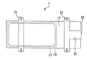
ヒートポンプ給湯室外機1の右側面部には、後述する貯湯装置と湯水のやり取りをするための外部水配管(図示せず)を接続可能な接続バルブとしての水入口バルブ29および給湯出口バルブ30が設置されている。水入口バルブ29および給湯出口バルブ30は、バルブ支持部材としてのバルブベッド28に固定されて支持されている。図示の構成では、水入口バルブ29が下側、給湯出口バルブ30が上側となるように、両者が縦に並んで配置されている。機械室14内では、水冷媒熱交換器8の水入口部と水入口バルブ29との間が内部水配管19により接続され、水冷媒熱交換器8の給湯出口部と給湯出口バルブ30との間が内部水配管20により接続されている。図3に示すように、バルブベッド28は、平板状をなしており、筐体の後面右側面部18bの右側面部分の外側に重なるように位置する。バルブベッド28と、筐体の後面右側面部18bの右側面部分との間には、緩衝部材23が介挿されている。緩衝部材23は、例えばゴム等の弾性材料または可撓性材料で構成されている。図4に示すように、バルブベッド28は、連結部31を介して第2脚部材22と連結されている。連結部31は、第2脚部材22からヒートポンプ給湯室外機1の右側面部に向かって略水平に延び、バルブベッド28の下端に繋がっている。本実施形態では、バルブベッド28、連結部31および第2脚部材22が一体的に形成されて一体化された構造となっているが、ボルト等の固定部材を介してこれらが連結固定された構成となっていてもよい。
A
上述したように、本実施形態では、バルブベッド28が第2脚部材22と連結されており、バルブベッド28が第2脚部材22によって直接的に保持されるので、ヒートポンプ給湯室外機1の運搬時や設置使用時等において、バルブベッド28は十分な保持強度を有している。なお、図1に示すように、筐体の後面右側面部18bの右側面部分には、水入口バルブ29および給湯出口バルブ30を保護するためのサービスパネル27が取り付け可能になっている。
As described above, in the present embodiment, the
次に、水冷媒熱交換器8の構造と機能について説明する。図3に示すように、水冷媒熱交換器8は、水配管8aに冷媒配管8bが密着接合され、水配管8a内の水と冷媒配管8b内の冷媒とで熱交換が行われるようになっている。水冷媒熱交換器8は、このような接合構造で、略直方体形状の収納容器12に収納可能となるように数回曲げ成形されている。吐出管5の接続側の冷媒配管8bと水配管8aとの接合端部8cからは、冷媒配管が接合されていない状態の水配管が給湯出口バルブ30まで延びて、内部水配管20を構成している。図示を省略するが、同様にして、反対側の接合端部8cからは、冷媒配管が接合されていない状態の水配管が水入口バルブ29まで延びて、内部水配管19を構成している。
Next, the structure and function of the water
次に、水冷媒熱交換器8以外の機能部品について説明する。詳細な図示を省略しているが、圧縮機2の内部には、冷媒の圧縮動作を行う圧縮部と、圧縮部と接続され圧縮部を駆動するモータとが組み込まれ、外部から電源供給されることによりモータと圧縮部とが所定の回転数で駆動するようになっている。圧縮機2の下部の脚板2aには、3〜4個の概略円筒形のゴムあるいは金属コイルの成形品の防振マウント3が取り付けられ、防振マウント3は、ベース17上面に設置され、圧縮機2を弾性的に支持している。また、冷媒を吸入するための吸入管4が圧縮機2に取り付けられ、冷媒を圧縮機2内部で圧縮後、吐出するための吐出管5が圧縮機2に取り付けられている。送風機6は、2〜3枚のプロペラ翼とプロペラ翼を回転駆動させるモータとが組み合わせられ、外部からの電源供給によりモータとプロペラ翼とが所定の回転数で回転するようになっている。膨張弁(図示せず)は冷媒流路本体外側面にコイル部材が取り付けられ、コイル部材に外部から通電することにより発生する電磁作用により、内部の流路抵抗調節部を稼動させて冷媒の流路抵抗を調節し、膨張弁の冷媒上流側高圧と冷媒下流側低圧を所定の圧力に調節している。空気冷媒熱交換器7は、複数回往復曲げ成形された長い冷媒配管に多数のアルミ薄板のフィンが密着して略平板状になっており、冷媒配管内の冷媒とフィン周辺の空気とで熱交換が行われるようになっており、送風機6による送風でフィン周辺を流れて通過する空気の風量が増やされて調節され、熱交換の量が増やされて調節されている。電気部品収納箱9は、圧縮機2、膨張弁、送風機6等を駆動制御するインバータ電源等の電気部品を収納し、インバータ電源は、圧縮機のモータの回転数を数十rps(Hz)〜百rps(Hz)程度の所定の回転数に変化させ、また、膨張弁の開度を所定の量に変化させ、また、送風機6の回転数を数百rpm〜千rpm程度の所定の回転数に変化させるよう制御している。
Next, functional parts other than the water
次に、ヒートポンプ給湯室外機1と貯湯装置との組み合わせ構成について説明する。ヒートポンプ給湯室外機1は、図示しない貯湯装置と組み合わされて使用される。貯湯装置には、例えば数百リットル程度の容量の貯湯タンクと、貯湯タンク内の水を外部に送る送水ポンプとが組み込まれる。送水ポンプの入口部は、貯湯タンク下部に接続された配管に接続される。送水ポンプの出口部には、外部水配管の一端が接続され、この外部水配管の他端がヒートポンプ給湯室外機1の水入口バルブ29に接続される。ヒートポンプ給湯室外機1の給湯出口バルブ30に一端が接続される外部水配管の他端は、貯湯タンクの上部に接続された配管に接続される。ヒートポンプ給湯室外機1と貯湯装置とは、これらの外部水配管と、電気配線とを介して接続される。このようにして、ヒートポンプ給湯室外機1と貯湯装置とで給湯回路が構成される。
Next, the combination structure of the heat pump hot water supply
次に、貯湯装置内の貯湯タンク内の湯量を増やすための沸き上げ運転におけるヒートポンプ給湯室外機1の動作について説明する。電気部品収納箱9に収納されたインバータ電源から圧縮機2内のモータに電源供給されるとモータが駆動し、モータと接続された圧縮機2内の圧縮部が駆動する。インバータ電源は、モータの回転数を数十rps(Hz)〜百rps(Hz)程度の所定の回転数に変化させ、冷媒が循環して行われるヒートポンプサイクルの循環速度および冷媒の流量を変化させることにより、所定の沸き上げ能力に調節制御している。また、電気部品収納箱9に収納されたインバータ電源から送風機6のモータに電源供給されるとモータが駆動し、モータと接続された送風機6のプロペラ翼が回転駆動する。インバータ電源は、モータの回転数を数百rpm〜千rpm程度に変化させ、空気冷媒熱交換器7を通過する空気の流量を変化させることにより、空気冷媒熱交換器7での冷媒と空気の熱交換量を所定の量に調節制御している。空気は、送風機6の後方に設置された空気冷媒熱交換器7の後方から吸い込まれ、空気冷媒熱交換器7を通過し、空気冷媒熱交換器7と反対側の前方へ排出される。また、電気部品収納箱9に収納されたインバータ電源から膨張弁の冷媒流路本体外側面に取り付けられたコイル部材に通電されると、冷媒流路本体内部の流路抵抗調節部を稼動させて冷媒の流路抵抗度を調節し、膨張弁の上流側高圧と下流側低圧の冷媒を所定の圧力に調節制御している。圧縮機2の回転数、送風機6の回転数、膨張弁の流路抵抗度は、ヒートポンプ給湯室外機1の設置環境および使用環境に応じて制御される。圧縮機2内の圧縮部が駆動すると圧縮部内で冷媒の圧縮動作が行われ、低圧冷媒は吸入管4から圧縮機2に吸入される。低圧冷媒は圧縮機2内の圧縮部で高温高圧冷媒に圧縮され、圧縮機2から吐出管5に吐出される。高温高圧冷媒は、吐出管5から水冷媒熱交換器8の冷媒入口部に流入し、水冷媒熱交換器8で低温水と熱交換し、低温水を加熱して高温湯を生成させる。高温高圧冷媒は、水冷媒熱交換器8でエンタルピを低下させ、温度を低下させて水冷媒熱交換器8の冷媒出口部から膨張弁の入口部に流入する。高圧冷媒は膨張弁で所定の圧力に減圧され温度降下し低温低圧冷媒となり膨張弁の出口部から空気冷媒熱交換器7の入口部に流入する。低温低圧冷媒は、空気冷媒熱交換器7で空気と熱交換し、エンタルピを増加させ、空気冷媒熱交換器7の出口部から吸入管4に流入し、圧縮機2に吸入される。このように冷媒が循環してヒートポンプサイクルが行われる。同時に、貯湯装置内の送水ポンプにより貯湯タンク内の下部の低温水が外部水配管を通ってヒートポンプ給湯室外機1に送られ、水入口バルブ29を介して内部水配管19に流入し、水冷媒熱交換器8の水入口部に流入し、水冷媒熱交換器8で冷媒と熱交換し加熱されて高温湯に生成される。生成された高温湯は、水冷媒熱交換器8の給湯出口部から内部水配管20に流入し、給湯出口バルブ30を介して外部水配管を通って貯湯装置に送られ、貯湯タンク上部に戻される。このようにして、貯湯タンク内の高温湯の量が増やす沸き上げ運転が行われる。
Next, the operation of the heat pump hot water supply
次に、圧縮機2の動作と、ヒートポンプ給湯室外機1の振動、騒音および低周波音の発生との関係について説明する。圧縮機2内の圧縮部が駆動し、圧縮部内で冷媒の圧縮動作が行われる時、冷媒の圧力変動および内部可動部品の動作により、圧縮機2には、上下方向、横方向等いくつかの方向の並進振動および回転振動が発生し、その周波数成分は、圧縮機2の回転数の整数倍で、低い倍数の周波数成分の方が大きく発生する傾向が高い。圧縮機の振動は、下記(ア)〜(オ)に例示する経路により、防振マウント3および配管を介してベース17および筐体各部に伝達する。
(ア)圧縮機2→防振マウント3→ベース17
(イ)圧縮機2→吸入管4→空気冷媒熱交換器7→ベース17→筐体各部
(ウ)圧縮機2→吐出管5→水冷媒熱交換器8→ベース17→筐体各部
(エ)圧縮機2→吐出管5→水冷媒熱交換器8→内部水配管19→水入口バルブ29→バルブベッド28→筐体の後面右側面部18b→筐体各部
(オ)圧縮機2→吐出管5→水冷媒熱交換器8→内部水配管20→給湯出口バルブ30→バルブベッド28→筐体の後面右側面部18b→筐体各部
Next, the relationship between the operation of the
(A)
(A)
このように、圧縮機2の振動がベース17および筐体各部に伝達し、ヒートポンプ給湯室外機1の振動、騒音および低周波音の原因となる可能性があるが、一般に、内部水配管19および内部水配管20は、冷媒配管より外径の大きい配管で構成されるため、剛性が高く、広範囲の周波数の振動を伝達し易い特性がある。このため、上記(エ)および(オ)の経路による振動伝達が、ヒートポンプ給湯室外機1の振動、騒音および低周波音の主要因となることが一般的である。
As described above, the vibration of the
これに対し、本実施形態のヒートポンプ給湯室外機1では、地面等の設置面に固定された第2脚部材22にバルブベッド28が連結されているため、バルブベッド28の振動および振幅が第2脚部材22によって確実に抑制される。このため、上記(エ)および(オ)の経路によって筐体各部に振動が伝達することを確実に抑制することができ、筐体各部の振動による振動、騒音および低周波音の発生を確実に抑制することができる。これにより、筐体各部への防振部材の貼り付け、筐体各部の板厚増加、筐体各部への補強部材の取り付け等の対策が不要または削減可能となるので、製造コストの増加を抑制することができる。
On the other hand, in the heat pump hot water supply
また、本実施形態では、バルブベッド28と、筐体の後面右側面部18bの右側面部分との間に介在した緩衝部材23が振動を吸収して減衰させるので、バルブベッド28から筐体の後面右側面部18bへの振動伝達をより確実に抑制することができる。このため、筐体各部の振動をより確実に抑制することができ、筐体各部の振動による振動、騒音および低周波音の発生をより確実に抑制することができる。
Further, in the present embodiment, the
以上説明したように、本実施形態によれば、ヒートポンプ給湯室外機1の振動、騒音および低周波音を低コストで効果的に低減することができる。給湯を行うヒートポンプ給湯室外機1は、深夜電力を利用して稼動される場合が多いため、深夜の振動や騒音、特に低周波音には使用者の関心が高い。このため、本実施形態による低周波音低減効果は著しく貢献する。また、ヒートポンプ給湯室外機1がCO2冷媒を使用する場合には、R410A冷媒を使用した空調機と比較して、圧縮機2に発生する振動は大きい。このため、本実施形態による低周波音低減効果は著しく貢献する。
As described above, according to the present embodiment, vibration, noise and low frequency sound of the heat pump hot water supply
なお、本実施形態では、水冷媒熱交換器8にて冷媒と水とが熱交換して湯を生成するヒートポンプ給湯室外機1を例に説明したが、本発明は、水以外の液状熱媒体(例えば、ブライン、不凍液等)と冷媒とが水冷媒熱交換器8にて熱交換する空気調和機用のヒートポンプ室外機などにも適用可能である。
In the present embodiment, the heat pump hot water
1 ヒートポンプ給湯室外機
2 圧縮機
2a 脚板
3 防振マウント
4 吸入管
5 吐出管
6 送風機
7 空気冷媒熱交換器
8 水冷媒熱交換器
8a 水配管
8b 冷媒配管
8c 接合端部
9 電気部品収納箱
9a 端子台
10 収納囲部材
11 収納蓋部材
12 収納容器
13 収納容器蓋
14 機械室
15 送風機室
16 仕切板
17 ベース
18a 前面左側面部
18b 後面右側面部
18c 上面部
19,20 内部水配管
21 第1脚部材
22 第2脚部材
23 緩衝部材
24,27 サービスパネル
28 バルブベッド
29 水入口バルブ
30 給湯出口バルブ
31 連結部
DESCRIPTION OF
Claims (4)
前記冷媒と水または液状熱媒体との熱交換を行う水冷媒熱交換器と、
前記冷媒回路および前記水冷媒熱交換器を収容する筐体と、
前記水または前記液状熱媒体が通る外部の配管である外部水配管を接続可能な接続バルブと、
前記接続バルブを支持するバルブ支持部材と、
前記筐体の内部で前記水冷媒熱交換器と前記接続バルブとの間を接続し、前記水または前記液状熱媒体が通る内部水配管と、
前記筐体の底部に設けられ、前記筐体を支持する脚部材と、
を備え、
前記バルブ支持部材と前記脚部材とを連結する連結部を含み、
前記連結部は、前記脚部材から略水平に延びて前記バルブ支持部材の下端に繋がっているヒートポンプ室外機。 A refrigerant circuit in which the enclosed refrigerant circulates;
A water-refrigerant heat exchanger for exchanging heat between the refrigerant and water or a liquid heat medium;
A housing for housing the refrigerant circuit and the water-refrigerant heat exchanger;
A connection valve capable of connecting an external water pipe which is an external pipe through which the water or the liquid heat medium passes;
A valve support member for supporting the connection valve;
An internal water pipe that connects between the water refrigerant heat exchanger and the connection valve inside the housing, and through which the water or the liquid heat medium passes;
A leg member provided at the bottom of the housing and supporting the housing;
With
Including a connecting portion for connecting the valve support member and the leg member;
The connecting portion is a heat pump outdoor unit that extends substantially horizontally from the leg member and is connected to the lower end of the valve support member.
Priority Applications (1)
| Application Number | Priority Date | Filing Date | Title |
|---|---|---|---|
| JP2012036030A JP5880123B2 (en) | 2012-02-22 | 2012-02-22 | Heat pump outdoor unit |
Applications Claiming Priority (1)
| Application Number | Priority Date | Filing Date | Title |
|---|---|---|---|
| JP2012036030A JP5880123B2 (en) | 2012-02-22 | 2012-02-22 | Heat pump outdoor unit |
Publications (3)
| Publication Number | Publication Date |
|---|---|
| JP2013170785A JP2013170785A (en) | 2013-09-02 |
| JP2013170785A5 JP2013170785A5 (en) | 2014-09-18 |
| JP5880123B2 true JP5880123B2 (en) | 2016-03-08 |
Family
ID=49264841
Family Applications (1)
| Application Number | Title | Priority Date | Filing Date |
|---|---|---|---|
| JP2012036030A Active JP5880123B2 (en) | 2012-02-22 | 2012-02-22 | Heat pump outdoor unit |
Country Status (1)
| Country | Link |
|---|---|
| JP (1) | JP5880123B2 (en) |
Families Citing this family (3)
| Publication number | Priority date | Publication date | Assignee | Title |
|---|---|---|---|---|
| JP2016011758A (en) * | 2014-06-27 | 2016-01-21 | 日立アプライアンス株式会社 | Outdoor unit of air conditioner and air conditioner |
| SG11201707968SA (en) * | 2015-05-11 | 2017-11-29 | Mitsubishi Electric Corp | Heat pump apparatus |
| WO2018150570A1 (en) * | 2017-02-20 | 2018-08-23 | 三菱電機株式会社 | Outdoor unit of air conditioner |
Family Cites Families (5)
| Publication number | Priority date | Publication date | Assignee | Title |
|---|---|---|---|---|
| JPH0413541Y2 (en) * | 1986-04-14 | 1992-03-30 | ||
| JPH10238818A (en) * | 1997-02-28 | 1998-09-08 | Yamaha Motor Co Ltd | Outdoor machine unit for engine driven heat pump device |
| JP2005147620A (en) * | 2003-11-19 | 2005-06-09 | Matsushita Electric Ind Co Ltd | Heat pump heat source unit |
| JP2008111569A (en) * | 2006-10-30 | 2008-05-15 | Daikin Ind Ltd | Outdoor unit for air conditioner |
| JP5348105B2 (en) * | 2010-10-08 | 2013-11-20 | 三菱電機株式会社 | Heat pump water heater outdoor unit |
-
2012
- 2012-02-22 JP JP2012036030A patent/JP5880123B2/en active Active
Also Published As
| Publication number | Publication date |
|---|---|
| JP2013170785A (en) | 2013-09-02 |
Similar Documents
| Publication | Publication Date | Title |
|---|---|---|
| JP5287614B2 (en) | Heat pump outdoor unit | |
| JP6747614B2 (en) | Heat pump hot water outdoor unit | |
| WO2019211894A1 (en) | Geothermal heat pump system | |
| JP5880123B2 (en) | Heat pump outdoor unit | |
| JP5754423B2 (en) | Heat pump water heater outdoor unit | |
| JP5348105B2 (en) | Heat pump water heater outdoor unit | |
| JP6841350B2 (en) | Heat pump hot water supply outdoor unit | |
| JP5630421B2 (en) | Heat pump hot water source | |
| JP5838295B2 (en) | Heat pump water heater | |
| JP5630427B2 (en) | Heat pump water heater outdoor unit | |
| JP2010243033A (en) | Heat pump outdoor unit | |
| JP2012145274A (en) | Heat pump hot water supply outdoor unit | |
| JP5625966B2 (en) | Heat pump water heater outdoor unit | |
| JP5867246B2 (en) | Heat pump water heater outdoor unit | |
| JP2011196586A (en) | Heat pump water heater | |
| JP6631706B2 (en) | Heat pump hot water outdoor unit | |
| JP2008151400A (en) | Hot-water supply outdoor unit and hot-water supply air conditioner | |
| JP6943346B2 (en) | Heat pump device | |
| JP6669306B2 (en) | Heat pump equipment | |
| US7137268B2 (en) | Vibration dampening device | |
| WO2023191092A1 (en) | Refrigeration cycle device | |
| JP6635202B2 (en) | Heat pump equipment | |
| JP5895125B2 (en) | Heat pump equipment | |
| WO2018109846A1 (en) | Outdoor unit for heat pump hot water supply | |
| JP6798628B2 (en) | Heat pump device |
Legal Events
| Date | Code | Title | Description |
|---|---|---|---|
| A521 | Request for written amendment filed |
Free format text: JAPANESE INTERMEDIATE CODE: A523 Effective date: 20140804 |
|
| A621 | Written request for application examination |
Free format text: JAPANESE INTERMEDIATE CODE: A621 Effective date: 20140804 |
|
| A977 | Report on retrieval |
Free format text: JAPANESE INTERMEDIATE CODE: A971007 Effective date: 20150417 |
|
| A131 | Notification of reasons for refusal |
Free format text: JAPANESE INTERMEDIATE CODE: A131 Effective date: 20150512 |
|
| A521 | Request for written amendment filed |
Free format text: JAPANESE INTERMEDIATE CODE: A523 Effective date: 20150609 |
|
| A131 | Notification of reasons for refusal |
Free format text: JAPANESE INTERMEDIATE CODE: A131 Effective date: 20150908 |
|
| A521 | Request for written amendment filed |
Free format text: JAPANESE INTERMEDIATE CODE: A523 Effective date: 20150929 |
|
| TRDD | Decision of grant or rejection written | ||
| A01 | Written decision to grant a patent or to grant a registration (utility model) |
Free format text: JAPANESE INTERMEDIATE CODE: A01 Effective date: 20160105 |
|
| A61 | First payment of annual fees (during grant procedure) |
Free format text: JAPANESE INTERMEDIATE CODE: A61 Effective date: 20160118 |
|
| R150 | Certificate of patent or registration of utility model |
Ref document number: 5880123 Country of ref document: JP Free format text: JAPANESE INTERMEDIATE CODE: R150 |
|
| R250 | Receipt of annual fees |
Free format text: JAPANESE INTERMEDIATE CODE: R250 |
|
| R250 | Receipt of annual fees |
Free format text: JAPANESE INTERMEDIATE CODE: R250 |
|
| R250 | Receipt of annual fees |
Free format text: JAPANESE INTERMEDIATE CODE: R250 |
|
| R250 | Receipt of annual fees |
Free format text: JAPANESE INTERMEDIATE CODE: R250 |
|
| R250 | Receipt of annual fees |
Free format text: JAPANESE INTERMEDIATE CODE: R250 |
|
| R250 | Receipt of annual fees |
Free format text: JAPANESE INTERMEDIATE CODE: R250 |