JP2012145221A - Seal member, and linear motion guide device using same - Google Patents
Seal member, and linear motion guide device using same Download PDFInfo
- Publication number
- JP2012145221A JP2012145221A JP2011267221A JP2011267221A JP2012145221A JP 2012145221 A JP2012145221 A JP 2012145221A JP 2011267221 A JP2011267221 A JP 2011267221A JP 2011267221 A JP2011267221 A JP 2011267221A JP 2012145221 A JP2012145221 A JP 2012145221A
- Authority
- JP
- Japan
- Prior art keywords
- rolling
- seal
- lip portion
- rolling element
- seal member
- Prior art date
- Legal status (The legal status is an assumption and is not a legal conclusion. Google has not performed a legal analysis and makes no representation as to the accuracy of the status listed.)
- Granted
Links
- 238000007789 sealing Methods 0.000 claims abstract description 31
- 230000003014 reinforcing effect Effects 0.000 claims abstract description 15
- 238000005096 rolling process Methods 0.000 claims description 151
- 230000002093 peripheral effect Effects 0.000 claims description 43
- 239000000314 lubricant Substances 0.000 claims description 33
- 230000001050 lubricating effect Effects 0.000 claims description 4
- 239000000428 dust Substances 0.000 abstract description 15
- 230000002787 reinforcement Effects 0.000 abstract description 3
- 230000008595 infiltration Effects 0.000 abstract 1
- 238000001764 infiltration Methods 0.000 abstract 1
- 239000004519 grease Substances 0.000 description 10
- 238000005461 lubrication Methods 0.000 description 7
- 238000003860 storage Methods 0.000 description 5
- 230000020169 heat generation Effects 0.000 description 3
- 239000002245 particle Substances 0.000 description 3
- 229920001971 elastomer Polymers 0.000 description 2
- 229920006168 hydrated nitrile rubber Polymers 0.000 description 2
- 239000000843 powder Substances 0.000 description 2
- 239000005060 rubber Substances 0.000 description 2
- 210000002268 wool Anatomy 0.000 description 2
- 229920000297 Rayon Polymers 0.000 description 1
- -1 and for example Substances 0.000 description 1
- 238000005520 cutting process Methods 0.000 description 1
- 238000010586 diagram Methods 0.000 description 1
- 238000003754 machining Methods 0.000 description 1
- 239000000463 material Substances 0.000 description 1
- 239000002184 metal Substances 0.000 description 1
- 238000012986 modification Methods 0.000 description 1
- 230000004048 modification Effects 0.000 description 1
- 230000002265 prevention Effects 0.000 description 1
- 239000002964 rayon Substances 0.000 description 1
- 238000007790 scraping Methods 0.000 description 1
- 239000000126 substance Substances 0.000 description 1
- 230000009466 transformation Effects 0.000 description 1
Images


Classifications
-
- F—MECHANICAL ENGINEERING; LIGHTING; HEATING; WEAPONS; BLASTING
- F16—ENGINEERING ELEMENTS AND UNITS; GENERAL MEASURES FOR PRODUCING AND MAINTAINING EFFECTIVE FUNCTIONING OF MACHINES OR INSTALLATIONS; THERMAL INSULATION IN GENERAL
- F16H—GEARING
- F16H25/00—Gearings comprising primarily only cams, cam-followers and screw-and-nut mechanisms
- F16H25/18—Gearings comprising primarily only cams, cam-followers and screw-and-nut mechanisms for conveying or interconverting oscillating or reciprocating motions
- F16H25/20—Screw mechanisms
- F16H25/24—Elements essential to such mechanisms, e.g. screws, nuts
- F16H25/2418—Screw seals, wipers, scrapers or the like
-
- F—MECHANICAL ENGINEERING; LIGHTING; HEATING; WEAPONS; BLASTING
- F16—ENGINEERING ELEMENTS AND UNITS; GENERAL MEASURES FOR PRODUCING AND MAINTAINING EFFECTIVE FUNCTIONING OF MACHINES OR INSTALLATIONS; THERMAL INSULATION IN GENERAL
- F16H—GEARING
- F16H25/00—Gearings comprising primarily only cams, cam-followers and screw-and-nut mechanisms
- F16H25/18—Gearings comprising primarily only cams, cam-followers and screw-and-nut mechanisms for conveying or interconverting oscillating or reciprocating motions
- F16H25/20—Screw mechanisms
- F16H25/24—Elements essential to such mechanisms, e.g. screws, nuts
-
- F—MECHANICAL ENGINEERING; LIGHTING; HEATING; WEAPONS; BLASTING
- F16—ENGINEERING ELEMENTS AND UNITS; GENERAL MEASURES FOR PRODUCING AND MAINTAINING EFFECTIVE FUNCTIONING OF MACHINES OR INSTALLATIONS; THERMAL INSULATION IN GENERAL
- F16J—PISTONS; CYLINDERS; SEALINGS
- F16J15/00—Sealings
- F16J15/16—Sealings between relatively-moving surfaces
- F16J15/32—Sealings between relatively-moving surfaces with elastic sealings, e.g. O-rings
- F16J15/3204—Sealings between relatively-moving surfaces with elastic sealings, e.g. O-rings with at least one lip
- F16J15/3224—Sealings between relatively-moving surfaces with elastic sealings, e.g. O-rings with at least one lip capable of accommodating changes in distances or misalignment between the surfaces, e.g. able to compensate for defaults of eccentricity or angular deviations
-
- F—MECHANICAL ENGINEERING; LIGHTING; HEATING; WEAPONS; BLASTING
- F16—ENGINEERING ELEMENTS AND UNITS; GENERAL MEASURES FOR PRODUCING AND MAINTAINING EFFECTIVE FUNCTIONING OF MACHINES OR INSTALLATIONS; THERMAL INSULATION IN GENERAL
- F16H—GEARING
- F16H25/00—Gearings comprising primarily only cams, cam-followers and screw-and-nut mechanisms
- F16H25/18—Gearings comprising primarily only cams, cam-followers and screw-and-nut mechanisms for conveying or interconverting oscillating or reciprocating motions
- F16H25/20—Screw mechanisms
- F16H25/22—Screw mechanisms with balls, rollers, or similar members between the co-operating parts; Elements essential to the use of such members
- F16H25/2204—Screw mechanisms with balls, rollers, or similar members between the co-operating parts; Elements essential to the use of such members with balls
- F16H25/2214—Screw mechanisms with balls, rollers, or similar members between the co-operating parts; Elements essential to the use of such members with balls with elements for guiding the circulating balls
-
- Y—GENERAL TAGGING OF NEW TECHNOLOGICAL DEVELOPMENTS; GENERAL TAGGING OF CROSS-SECTIONAL TECHNOLOGIES SPANNING OVER SEVERAL SECTIONS OF THE IPC; TECHNICAL SUBJECTS COVERED BY FORMER USPC CROSS-REFERENCE ART COLLECTIONS [XRACs] AND DIGESTS
- Y10—TECHNICAL SUBJECTS COVERED BY FORMER USPC
- Y10T—TECHNICAL SUBJECTS COVERED BY FORMER US CLASSIFICATION
- Y10T74/00—Machine element or mechanism
- Y10T74/19—Gearing
- Y10T74/19642—Directly cooperating gears
- Y10T74/19698—Spiral
- Y10T74/19702—Screw and nut
- Y10T74/19744—Rolling element engaging thread
Abstract
Description
本発明は、ボールねじ装置などの直線運動案内装置に用いられるシール部材及びこのシール部材が適用されたボールねじ装置などの直線運動案内装置に関する。 The present invention relates to a seal member used in a linear motion guide device such as a ball screw device and a linear motion guide device such as a ball screw device to which the seal member is applied.
ボールねじ装置は、内周面に螺旋溝が形成されたナットと、外周面に螺旋溝が形成されたねじ軸と、ナットの螺旋溝とねじ軸の螺旋溝で形成される軌道溝の間に配列された複数の転動体とを備えている。また、ナットには、ナットの螺旋溝の一端と他端を連絡する無限循環路が形成されており、ナットの螺旋溝の一端まで転走した転動体は、無限循環路を通過してナットの螺旋溝の他端まで循環する。このような構成により、ボールねじ装置はナットがねじ軸の回転に従ってねじ軸の軸線方向に直線往復運動することが可能となっている。 The ball screw device includes a nut having a spiral groove formed on the inner peripheral surface, a screw shaft having a spiral groove formed on the outer peripheral surface, and a raceway groove formed by the spiral groove of the nut and the spiral groove of the screw shaft. A plurality of rolling elements arranged. The nut also has an infinite circuit that connects one end and the other end of the nut's spiral groove, and the rolling elements that have rolled to one end of the nut's spiral groove pass through the endless circuit and pass through the nut. Circulate to the other end of the spiral groove. With such a configuration, the ball screw device allows the nut to reciprocate linearly in the axial direction of the screw shaft as the screw shaft rotates.
このボールねじ装置においてはナットが長尺のねじ軸に沿って移動していることから、ねじ軸にワークの切削粉や塵芥などの塵埃が異物として付着した状態でナットが移動すると、転動体転走溝を転走する転動体がこれらの異物を噛み込んでしまい、ねじ軸の回転に対するナットの移動精度が早期に低下してしまう。このため、ボールねじ装置を実際に使用するに当たっては、ナットの軸方向の両端にナットとねじ軸との隙間を密封するシール部材を装着し、ナットの移動に併せてねじ軸に付着した異物をシール部材で除去するように構成するのが一般的である。 In this ball screw device, since the nut moves along the long screw shaft, if the nut moves while foreign matter such as cutting powder or dust is attached to the screw shaft, the rolling element rolls. The rolling elements that roll in the running grooves bite these foreign substances, and the movement accuracy of the nut with respect to the rotation of the screw shaft is lowered early. For this reason, when actually using the ball screw device, seal members that seal the gap between the nut and the screw shaft are attached to both ends of the nut in the axial direction, and foreign matter adhering to the screw shaft is removed along with the movement of the nut. Generally, it is configured to be removed by a sealing member.
例えば、下記特許文献1に記載されているように、内周面に螺旋溝が形成されたナットと、外周面に螺旋溝が形成されたねじ軸と、ナットの螺旋溝とねじ軸の螺旋溝で形成される軌道溝の間に配置されたボールと、ナットの軸方向両端または一端にそれぞれ複数配置されたリング状のシールを備え、前記シールはナットに固定される縁部を備えた本体と、ねじ軸の外周面および螺旋溝に弾性変形状態で接触するリップ部とを有し、隣り合うシールの間に潤滑材含有部材が配置されているボールねじ装置が知られている。 For example, as described in Patent Document 1 below, a nut having a spiral groove formed on the inner peripheral surface, a screw shaft having a spiral groove formed on the outer peripheral surface, a spiral groove of the nut, and a spiral groove of the screw shaft A ball disposed between the raceway grooves formed by the ring, and a plurality of ring-shaped seals disposed at both ends or one end in the axial direction of the nut, the seal including a body having an edge fixed to the nut; A ball screw device has been known that has a lip portion that contacts the outer peripheral surface of a screw shaft and a spiral groove in an elastically deformed state, and a lubricant-containing member is disposed between adjacent seals.
このようなボールねじ装置によると、隣り合うシールの間に潤滑剤含有部材が配置されているため、グリースを充填した場合のようなトルクの増加を招くことなく、両シールのリップ部の潤滑がなされ、高いシール性を確保することができるようになっている。 According to such a ball screw device, since the lubricant-containing member is arranged between adjacent seals, the lip portions of both seals can be lubricated without causing an increase in torque as in the case of filling with grease. As a result, high sealing performance can be secured.
しかしながら、従来のボールねじ装置は、シールを弾性変形させてねじ軸の外周面および螺旋溝に接触させることで、シールに締め代を設けて取り付けを行っているため、シールやねじ軸の加工誤差が生じることによって精度よくシールを取り付けることができず、ボールねじ装置をレーザー加工機などに適用した場合、レーザー加工機の加工によって生じる粒径が数10μm程度の微細な加工粉をシールすることができないといった問題があった。 However, since the conventional ball screw device elastically deforms the seal and makes contact with the outer peripheral surface of the screw shaft and the spiral groove, the seal is provided with a tightening margin, so that a processing error of the seal and the screw shaft is caused. When the ball screw device is applied to a laser processing machine or the like, it is possible to seal fine machining powder having a particle size of about several tens of μm generated by the processing of the laser processing machine. There was a problem that I couldn't.
また、従来のボールねじ装置は、シールを弾性変形させてねじ軸の外周面および螺旋溝に接触させているので、接触による摩擦熱の発生、トルクの増大といった課題を有しており、さらに、経年使用により、シールが摩耗した場合、シール性能が著しく低下するといった問題があった。 In addition, since the conventional ball screw device elastically deforms the seal and makes contact with the outer peripheral surface of the screw shaft and the spiral groove, it has problems such as generation of frictional heat due to contact and increase in torque. When the seal is worn out over time, there is a problem that the seal performance is remarkably deteriorated.
さらに、転動体転走部を有する軸部材と、前記転動体転走部に対向する負荷転動体転走部を有する移動部材と、前記転動体転走部と前記負荷転動体転走部との間に転がり運動可能に配列される複数の転動体と、前記移動部材の少なくとも一端に取り付けられるシール装置を備える直線運動案内装置においても、同様の問題を有していた。 Furthermore, a shaft member having a rolling element rolling part, a moving member having a load rolling element rolling part facing the rolling element rolling part, and the rolling element rolling part and the load rolling element rolling part The linear motion guide device including a plurality of rolling elements arranged so as to be capable of rolling motion therebetween and a seal device attached to at least one end of the moving member has the same problem.
本発明は、上記課題を解決するために成されたものであって、シールに過大な締め代を設けることなく、確実に、軸部材に対してシールを接触させることで、直線運動案内装置の移動部材の外部からの塵埃等の侵入を確実に防止でき、微細な塵埃等も確実にシールすることができる高防塵シール機能を備えたシール部材及びこのシール部材を有するボールねじ装置又は直線運動案内装置を提供することを目的とする。また、移動部材内部に保持されたグリースなどの潤滑剤が移動部材外部に飛散することを防止することができるシール部材及びこのシール部材を有するボールねじ装置及び直線運動案内装置を提供することを目的とする。 The present invention has been made to solve the above-described problems. The linear motion guide device is provided by reliably bringing the seal into contact with the shaft member without providing an excessive tightening allowance for the seal. A sealing member having a high dust-proof sealing function that can reliably prevent entry of dust and the like from the outside of the moving member, and can also reliably seal fine dust and the like, and a ball screw device or linear motion guide having the sealing member An object is to provide an apparatus. Another object of the present invention is to provide a seal member capable of preventing lubricant such as grease held inside the moving member from scattering outside the moving member, a ball screw device having the seal member, and a linear motion guide device. And
本発明に係るシール部材は、軸部材と移動部材との間に転がり運動可能に複数の転動体を介在させた直線運動案内装置における前記移動部材の軸方向の端面に取り付けられるシール部材において、前記シール部材は、前記移動部材に取り付けられる本体部と、前記軸部材の外周に接触するリップ部とを有し、前記リップ部は、軸方向の断面形状が前記軸方向に対して傾斜した斜面を備え、前記本体部は、前記リップ部を前記軸部材の径方向に付勢する付勢手段を備えると共に、前記斜面側に、前記本体部を補強する補強部を備え、前記リップ部の軸方向の断面形状において、前記付勢手段は、前記リップ部の先端よりも前記補強部側に位置していることを特徴とする。 The seal member according to the present invention is a seal member attached to an end face in the axial direction of the moving member in a linear motion guide device in which a plurality of rolling elements are interposed between the shaft member and the moving member so as to allow rolling motion. The seal member has a main body portion attached to the moving member and a lip portion that contacts an outer periphery of the shaft member, and the lip portion has a slope whose axial cross-sectional shape is inclined with respect to the axial direction. The body portion includes a biasing unit that biases the lip portion in the radial direction of the shaft member, and further includes a reinforcing portion that reinforces the body portion on the slope side, and the axial direction of the lip portion In the cross-sectional shape, the urging means is located closer to the reinforcing portion than the tip of the lip portion.
また、本発明に係るボールねじ装置は、外周面に螺旋状の転動体転走溝を有するねじ軸と、内周面に前記転動体転走溝に対向する負荷転動体転走溝を有するナットと、前記転動体転走溝と、前記負荷転動体転走溝との間に転がり運動可能に配列される複数の転動体と、前記ナットの少なくとも一端に取り付けられるシール装置を備えるボールねじ装置において、前記シール装置は、前記ナットに取り付けられる本体部と、前記ねじ軸の外周または前記転動体転走溝に接触するリップ部とを有するシール部材を備え、前記リップ部は、軸方向の断面形状が前記軸方向に対して傾斜した斜面を備え、前記本体部は、前記リップ部を前記ねじ軸の径方向に付勢する付勢手段を備えると共に、前記斜面側に、前記本体部を補強する補強部を備え、前記リップ部の軸方向の断面形状において、前記付勢手段は、前記リップ部の先端よりも前記補強部側に位置していることを特徴とする。 The ball screw device according to the present invention includes a screw shaft having a spiral rolling element rolling groove on an outer peripheral surface, and a nut having a load rolling element rolling groove facing the rolling element rolling groove on an inner peripheral surface. A ball screw device comprising: a plurality of rolling elements arranged so as to allow rolling motion between the rolling element rolling grooves and the loaded rolling element rolling grooves; and a seal device attached to at least one end of the nut. The seal device includes a seal member having a main body portion attached to the nut and a lip portion that contacts an outer periphery of the screw shaft or the rolling element rolling groove, and the lip portion has an axial sectional shape. Includes a slope inclined with respect to the axial direction, and the body portion includes a biasing means for biasing the lip portion in the radial direction of the screw shaft and reinforces the body portion on the slope side. A reinforcing portion, In the axial direction of the cross-sectional shape of the-up portion, the biasing means is characterized by being located on the reinforcing portion side than the tip of the lip portion.
本発明によれば、シール部材が一定の締め代をもって線接触で軸部材に接触するため、発熱量が少なく、確実に異物を除去することができる。また、付勢手段によってシール部材を軸部材の径方向に付勢しているので、リップ部の先端が摩耗しても常に接触状態を維持することができる。さらに、リップ部の一端面を斜面に形成すると共に、付勢手段がリップ部先端よりも補強部側にずらして配置しているので、リップ部を常に一定の方向に変形させることができ、ボールねじ装置又は直線運動案内装置の外部から塵埃等が侵入することを確実に防止できる他、移動部材の内部から潤滑剤が飛散することを防止することができる。 According to the present invention, since the seal member comes into contact with the shaft member by line contact with a certain tightening margin, the amount of generated heat is small, and foreign matters can be reliably removed. Further, since the sealing member is urged in the radial direction of the shaft member by the urging means, the contact state can always be maintained even if the tip of the lip portion is worn. Further, the lip portion has one end surface formed on a slope, and the urging means is arranged so as to be shifted from the tip of the lip portion toward the reinforcing portion side, so that the lip portion can always be deformed in a certain direction, and the ball In addition to reliably preventing dust and the like from entering from the outside of the screw device or the linear motion guide device, it is possible to prevent the lubricant from scattering from the inside of the moving member.
以下、本発明に係るボールねじ装置の実施形態について図面を参照しつつ説明する。なお、以下の実施形態は、各請求項に係る発明を限定するものではなく、また、実施形態の中で説明されている特徴の組み合わせの全てが発明の解決手段に必須であるとは限らない。 Hereinafter, embodiments of a ball screw device according to the present invention will be described with reference to the drawings. The following embodiments do not limit the invention according to each claim, and all combinations of features described in the embodiments are not necessarily essential to the solution means of the invention. .
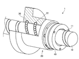
図1は、本実施形態に係るボールねじ装置の構造を示す一部断面斜視図であり、図2は、本実施形態に係るボールねじ装置の構造を示す一部断面図であり、図3は、本実施形態に係るボールねじ装置のシール装置の分解図であり、図4は、本実施形態に係るボールねじ装置に用いられるシール部材の正面図であり、図5は、図4におけるA−A断面図であり、図6は、図5におけるB部拡大図であり、図7は、シール部材がねじ軸に接触する状態を示す状態図であり、図8は、本実施形態に係るボールねじ装置の潤滑手段を軸方向から示した図であり、図9は、本発明に係るボールねじ装置の実施形態に用いられるシール部材の接触状態を説明するための図である。 1 is a partial cross-sectional perspective view showing the structure of the ball screw device according to the present embodiment, FIG. 2 is a partial cross-sectional view showing the structure of the ball screw device according to the present embodiment, and FIG. FIG. 4 is an exploded view of the sealing device of the ball screw device according to the present embodiment, FIG. 4 is a front view of a sealing member used in the ball screw device according to the present embodiment, and FIG. 6 is a cross-sectional view of A, FIG. 6 is an enlarged view of a portion B in FIG. 5, FIG. 7 is a state diagram showing a state where the seal member is in contact with the screw shaft, and FIG. FIG. 9 is a view showing the lubricating means of the screw device from the axial direction, and FIG. 9 is a view for explaining the contact state of the seal member used in the embodiment of the ball screw device according to the present invention.
図1は、本実施形態に係るボールねじ装置1を示すものである。本実施形態に係るボールねじ装置1は、外周面に所定のリードで螺旋状の転動体転走溝11が形成された軸部材としてのねじ軸10と、複数の転動体30を介してねじ軸10に螺合するとともに該転動体30の無限循環路(不図示)を備えた移動部材としてのナット20とから構成されており、これらねじ軸10とナット20との相対的な回転により該ナット20がねじ軸10の軸方向へ運動するように構成されている。また、この転動体転走溝11は、円滑な転動体30の転走が実現できるような精度での表面加工が施されている。なお、転走面の形状については、ゴシックアーチ形状であってもサーキュラアーク形状であっても構わない。
FIG. 1 shows a ball screw device 1 according to this embodiment. The ball screw device 1 according to this embodiment includes a
図1及び2に示すように、ナット20は、内周面に転動体転走溝11に対向する負荷転動体転走溝22が形成され、略円筒形状をしたナット本体21と、転動体転走溝11およびねじ軸10の外周面に潤滑剤を塗布する潤滑手段50とを備えている。なお、上述したように転動体転走溝11と負荷転動体転走溝22の間には複数の転動体30が配列されており、ナット20は、ねじ軸10に対して転動体30を介して組み付けられている。
As shown in FIGS. 1 and 2, the
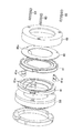
ナット20の軸方向の端部には、ナット20の内部と外部とをシールするシール装置40が取り付けられている。シール装置40は、潤滑手段50を介してナット20に組み付けられる略円環状の本体部42と、ねじ軸10の外周面および転動体転走溝11に接触するように、本体部42の内周面から径方向内側に向けて斜めに延びるリップ部43とを有するシール部材41を一対隣接させて組み付けられている。リップ部43は、ねじ軸10の外周面や転動体転走溝11に付着した塵埃等を掻き取る機能を有している。一対のシール部材41,41は、互いに背面を合わせるように隣接しており、リップ部43が、隣接する本体部42の当接面から互いに離間する方向に延び、断面略ハの字状に配置されている。
A
さらに、シール部材41の端部には、軸方向の投影形状がシール部材41と略同一形状に形成された板部材48が取り付けられている。板部材48はシール部材41を軸方向に保持するように組み付けられた円環状の部材であり、その内周面は、ねじ軸10の外周面および転動体転走溝11の転走面から所定の隙間を有して組み付けられている。この内周面は、所定の隙間よりも大きな塵埃等をシールするスクレーパ部48aとして作用する。
Further, a
図3に示すように、一対のシール部材41,41は、潤滑手段50の端部にカラー41aを介して組み付けられている。カラー41aは、後述するボルト60が挿通される部材であり、シール部材41,41の位置決めを行っている。このように、シール装置40は、一対のシール部材41,41および板部材48をこの順に配置した状態でケース49を最外周及び最端部に被覆させ、ボルト60で締結することによってシール装置40が構成されている。
As shown in FIG. 3, the pair of
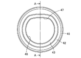
次に図4から6を参照してシール部材41について詳述する。図4に示すように、本体部42は略円環状に形成されている。図5に示すように、リップ部43は本体部42の内周面から内径方向に向かって突出して形成されている。なお、リップ部43は、断面舌片状に形成されており、ねじ軸10との摺動接触がなされる部位を意味する。
Next, the
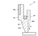
図6に示すように、シール部材41は、本体部42に形成された溝部45に付勢手段44が組み付けられている。本実施形態において、付勢手段44はばね部材として円環状のコイルスプリングが用いられている。本体部42の斜面43a側の軸方向の端部には本体部42を補強する補強部42aが取り付けられている。補強部42aは、円環状の金属板によって構成されていると好適である。
As shown in FIG. 6, the sealing
リップ部43は、軸方向の断面形状が、一端面が軸方向に対して傾斜した斜面43aに形成されており、この斜面43aの反対面は軸方向と略垂直に交わる垂直面43bに形成されている。また、斜面43aの本体部42と連続する連結部は、薄肉に形成された変形部42bが形成されている。
The
また、リップ部43の先端位置は、付勢手段44が取り付けられる溝部45に対して垂直面43b側にずらされて配置されている。即ち、付勢手段44の中心C1は、リップ部43の先端C2と軸方向に沿って互いに離間しており、リップ部43の先端は垂直面43b側に、付勢手段44の中心C1は斜面43a側にそれぞれ配置されている。なお、付勢手段44を取り付ける溝部45は、上述したように斜面43a側に配置されるので、変形部42bをより薄肉に形成することができる。
Further, the tip position of the
さらに、図4に示すように、リップ部43は、内周形状が円弧状の円弧部46と、円弧形状から内径方向に膨出した膨出部47とを備えている。円弧部46は、ねじ軸10の外周面と接触してねじ軸10の外周面をシールするように作用し、膨出部47は、転動体転走溝11の転走面と接触して転動体転走溝11の転走面をシールするように作用する。
Further, as shown in FIG. 4, the
このように、シール部材41は、付勢手段44によってねじ軸10方向に一定の圧力を付与されて接触しているので、図7に示すように、ねじ軸10の外周面および転動体転走溝11の転走面のいずれに対しても一定の圧力で接触することができる。また、リップ部43の先端形状はR形状に形成されているので、転動体転走溝11の転走面とねじ軸10の外周面とが連続する箇所においても柔軟に接触することができる。なお、シール部材41は、ねじ軸10に対して一定の圧力を付与できるように柔軟性のある部材で形成されており、例えばゴムで形成されている。なお、ゴムは、耐熱・耐油・耐摩耗性に優れた水素化アクリロニトリル・ブタジエンゴム(H−NBR)が好適に用いられる。
Thus, since the sealing
また、図9に示すように、シール部材41は、軸方向の断面形状が軸方向に対して傾斜した斜面43aと垂直面43bによって形成されているので、垂直面43b側の剛性は、斜面43a側の剛性よりも高く形成されている。さらに、リップ部43の先端が付勢手段44の中心よりも垂直面43b側に形成されているので、付勢手段44の付勢力によってリップ部43を変形方向Dに沿ってリップの先端が垂直面43b側に屈曲するようにリップ部43を変形させてねじ軸10の外周面及び転動体転走溝11の転走面に接触させることができる。
Further, as shown in FIG. 9, the
さらに、シール部材41は、斜面43a側に補強部42aを備えて本体部の42の斜面43a側の剛性を向上させると共に、斜面43aと本体部42との連結部には変形部42bが形成してリップ部43の斜面43a側の剛性を低くしているので、より変形方向Dに沿った変形を促すことができる。
Further, the
このように、シール部材41は、リップ部43がねじ軸10の外周面及び転動体転走溝11の転走面に接触した状態において、変形方向Dに沿って一定の方向に変形するので、変形方向Dを塵埃等の侵入方向又は潤滑剤の漏出方向と対向するように配置すれば、容易にシール性能を向上させることができる。
Thus, the
次に図2および図8を参照して、潤滑手段50について説明を行う。潤滑手段50は、転動体転走溝11の転走面やねじ軸10の外周面に塗布される潤滑剤を保持する潤滑剤保持部51と、転動体転走溝11およびねじ軸10の外周面に摺接して潤滑剤を転動体転走溝11およびねじ軸10の外周面に塗布する潤滑剤供給部52とを備えている。潤滑剤保持部51は、内部に潤滑剤を貯蔵する貯蔵体51aを有しており、該貯蔵体51aは、例えば、フェルトからなっている。なお、貯蔵体51aのフェルトには、潤滑剤を適切に貯蔵できる材質が用いられ、例えば空隙率約80%のレーヨン+羊毛フェルトが用いられる。
Next, the lubrication means 50 will be described with reference to FIGS. The lubrication means 50 includes a
また、潤滑剤供給部52は、貯蔵体51aと接触する一定の厚みのフェルトからなっており、潤滑剤供給部52のフェルトの空隙率は貯蔵体51aの空隙率よりも低く設定されている。潤滑剤供給部52のフェルトには、例えば空隙率50%程度の羊毛フェルトが用いられる。さらに、図8に示すように、潤滑剤供給部52は、潤滑剤保持部51からナット20の内周方向に突出するように複数形成されている。複数の潤滑剤供給部52は、突出量の大きい第1潤滑剤供給部52aと、突出量の小さな第2潤滑剤供給部52bとを有している。第1潤滑剤供給部52aは、転動体転走溝11の転走面に接触し、第2潤滑剤供給部52bはねじ軸10の外周面に接触する。
Further, the
このように、潤滑手段50は、転動体転走溝11およびねじ軸10の外周面に接触することで、転動体転走溝11およびねじ軸10の外周面に潤滑剤を塗布することができる。転動体転走溝11に塗布された潤滑剤は、円滑な転動体の転走に寄与し、ねじ軸10の外周面に塗布された潤滑剤は、ねじ軸10の外周面とリップ部43とが摺接することによる摩耗からリップ部43を保護することができる。
Thus, the lubrication means 50 can apply the lubricant to the outer circumferential surfaces of the rolling
以上説明したように、本実施形態に係るボールねじ装置1は、リップ部43が軸方向に対して傾斜した斜面43aを備え、斜面43aの反対面に補強部42aを備えると共に、付勢手段44の中心C1がリップ部43の先端よりも補強部側に位置しているので、シール部材41は、リップ部43がねじ軸10の外周面及び転動体転走溝11の転走面に接触した状態において、変形方向Dに沿って一定の方向に変形させることができ、変形方向Dを塵埃等の侵入方向又はグリースの飛散方向と対向するように配置すれば、容易にシール性能を向上させることができる。
As described above, in the ball screw device 1 according to the present embodiment, the
また、リップ部43の他端面は、軸方向と略垂直に交わる垂直面43bに形成されているので、リップ部43の垂直面43b側の剛性を向上させることができ、リップ部43がねじ軸10の外周面及び転動体転走溝11の転走面に接触した状態において、変形方向Dに沿って常に一定の方向に変形させるように促すことができる。
Further, since the other end surface of the
また、リップ部43の斜面43aと本体部42との連結部は、薄肉に形成された変形部42bが形成されているので、リップ部43がねじ軸10の外周面及び転動体転走溝11の転走面に接触した状態において、変形方向Dに沿って常に一定の方向に変形させるように促すことができる。
Further, since the connecting portion between the
また、シール部材41は、一対用いられ、リップ部43が互いに隣接する本体部42の当接面から互いに離間する方向に延びるように配置されているので、塵埃等の侵入を防止及びグリースの飛散防止の両立を図ることができる高防塵シールを達成することができる。
In addition, a pair of
また、付勢手段44は、シール部材41の本体部42に形成された溝部45に組み付けられたばね部材として構成されているので、簡便な構成で高防塵シールを達成することができる。
Further, since the urging means 44 is configured as a spring member assembled in the
さらに、リップ部43は、ねじ軸10の外周面に接触する円弧部と転動体転走溝11の転走面に接触する膨出部とを備えるので、ねじ軸10の外周面と転動体転走溝11の転走面の両方を確実にシールすることができる。また、互いに隣接するシール部材41の本体部42の当接面から互いに離間する方向に略ハの字状に配置されているので、一対のシール部材41,41のうち内側(ナット20側)に配置されたシール部材41がナット20の内部からのグリース等の飛散を防止し、且つ外側に配置されたシール部材41がナット20の外部から塵埃等が侵入することを防止することができる。
Furthermore, since the
またさらに、シール装置40の端部には、ねじ軸10の外周面および転動体転走溝11の転走面に対して所定の隙間を持って配置されるスクレーパ部48aを備える板部材48を備えているので、スクレーパ部48aによって所定の隙間よりも大きな塵埃等が侵入することを防止することができる。
Furthermore, a
また、ナット20は、ねじ軸10の外周面および転動体転走溝11の転走面に潤滑剤を塗布する潤滑手段50を備えているので、円滑な転動体の転走に寄与するとともに、ねじ軸10の外周面とリップ部43とが摺接することによる摩耗からリップ部43を保護することができる。
Moreover, since the
本実施形態に係るボールねじ装置と従来のシール部材を備えたボールねじ装置の異物侵入量,密封性能,発熱量を測定した。従来のシール部材は、非接触式および接触式の2種類について測定を行った。 The foreign matter intrusion amount, sealing performance, and heat generation amount of the ball screw device according to this embodiment and the ball screw device provided with the conventional seal member were measured. Conventional seal members were measured for two types, a non-contact type and a contact type.
異物侵入量の測定はねじ軸の外周面および転動体転走溝に粒径が60μm以下の異物を混入したグリースを一定量塗布し、ナットを連続的に往復運動させた後、ナット内のグリースの異物の濃度を測定して行った。 To measure the amount of foreign matter intrusion, apply a certain amount of grease mixed with foreign matter with a particle size of 60 μm or less to the outer peripheral surface of the screw shaft and the rolling element rolling groove, and continuously reciprocate the nut. The concentration of foreign matter was measured.
その結果、本実施形態に係るボールねじ装置は、異物濃度が0.017〜0.034%Wtという結果が得られ、従来の非接触式のシール部材では、0.175〜0.278%Wt、従来の接触式のシール部材では、0.145〜0.205%Wtという結果が得られた。このように、本実施形態に係るボールねじ装置は、従来のシール部材に比べて大幅に異物の侵入を防止しており、粒径が数10μmの塵埃に対しても高い防塵性能を有しているという結果となった。 As a result, the ball screw device according to the present embodiment has a result that the foreign matter concentration is 0.017 to 0.034% Wt, and the conventional non-contact type seal member has 0.175 to 0.278% Wt. In the conventional contact-type seal member, a result of 0.145 to 0.205% Wt was obtained. As described above, the ball screw device according to the present embodiment greatly prevents the intrusion of foreign matters as compared with the conventional seal member, and has a high dustproof performance against dust having a particle size of several tens of μm. As a result.
密封性能の測定は、ナットの内部に一定量のグリースを封入し、ナットを連続的に往復運動させた後、ねじ軸に付着したグリースの量を計量することで、ナットの外部に飛散したグリースの量を測定した。 Sealing performance is measured by enclosing a certain amount of grease inside the nut, continuously reciprocating the nut, and then measuring the amount of grease adhering to the screw shaft. The amount of was measured.
その結果、本実施形態に係るボールねじ装置は、グリースの飛散量が0.23〜0.36gという結果が得られ、従来の非接触式のシール部材では、2.34〜3.28g、従来の接触式のシール部材では、0.50〜0.55gという結果が得られた。このように、本実施形態に係るボールねじ装置は、従来のシール部材に比べてグリースの飛散量が小さく、ナット内の密封性能が高いという結果を得た。 As a result, the ball screw device according to the present embodiment has a result that the amount of grease scattering is 0.23 to 0.36 g, and the conventional non-contact type seal member is 2.34 to 3.28 g. In the contact type seal member, a result of 0.50 to 0.55 g was obtained. As described above, the ball screw device according to this embodiment has a result that the amount of grease scattered is small and the sealing performance in the nut is high as compared with the conventional seal member.
発熱量の測定は、ナットを連続的に往復運動させ、30分毎のナットの外表面およびねじ軸の外表面の温度を測定した。また、測定した温度のうち最も高い温度を集計してその増加量を比較した。 The calorific value was measured by continuously reciprocating the nut and measuring the temperature of the outer surface of the nut and the outer surface of the screw shaft every 30 minutes. Moreover, the highest temperature was totaled among the measured temperatures, and the increase amount was compared.
その結果、本実施形態に係るボールねじ装置1は、ナット側で3.2℃/ねじ軸側で5.2℃の発熱の増加量が得られ、従来の非接触式のシール部材では、ナット側で10.0℃/ねじ軸側で9.3℃、従来の接触式シール部材では、ナット側で20℃/ねじ軸側で28.7℃という結果が得られた。このように、本実施形態に係るボールねじ装置は、従来の非接触式及び接触式のシール部材に比べて大幅に低い値を示しており、発熱量が非常に小さいという結果を得た。 As a result, the ball screw device 1 according to the present embodiment has an increase in heat generation of 3.2 ° C. on the nut side / 5.2 ° C. on the screw shaft side. The result was 10.0 ° C. on the side / 9.3 ° C. on the screw shaft side, and 20 ° C. on the nut side / 28.7 ° C. on the screw shaft side with the conventional contact seal member. As described above, the ball screw device according to the present embodiment shows a significantly lower value than the conventional non-contact type and contact type seal members, and the heat generation amount is very small.
なお、本発明は、上記実施形態に限られることはなく、本発明の要旨を変更しない範囲において、種々の変更が可能である。例えば、本実施形態では、ボールねじ装置に適用した場合について説明したが、ボールスプライン等の直線運動案内装置に適用しても構わない。 The present invention is not limited to the above embodiment, and various modifications can be made without departing from the scope of the present invention. For example, in the present embodiment, the case where the present invention is applied to a ball screw device has been described. However, the present invention may be applied to a linear motion guide device such as a ball spline.
ボールスプラインは、長手方向に沿って複数条の転動体転走部が形成された軌道部材としてのスプライン軸と、このスプライン軸が貫通する中空孔を有して略円筒形状に形成されるとともに、複数の転動体を介してスプライン軸に取り付けられた移動部材としてのスプラインナットとから構成されている。スプラインナットには転動体転走部の条数と同数の無限循環路が形成されており、スプライン軸の転動体転走部を転走した転動体がスプラインナットに形成された無限循環路を循環することにより、かかるスプラインナットがスプライン軸に沿って自在に直線往復運動することが可能となっている。 The ball spline is formed in a substantially cylindrical shape having a spline shaft as a race member in which a plurality of rolling element rolling portions are formed along the longitudinal direction, and a hollow hole through which the spline shaft passes, It is comprised from the spline nut as a moving member attached to the spline shaft via the some rolling element. The spline nut has the same number of endless circulation paths as the rolling element rolling parts, and the rolling elements that have run through the rolling part rolling part of the spline shaft circulate through the infinite circulation path formed in the spline nut. As a result, the spline nut can freely reciprocate linearly along the spline shaft.
また、転動体にはボールのほか、円筒状のローラを用いても構わない。その様な変更又は改良を加えた形態も本発明の技術的範囲に含まれうることが、特許請求の範囲の記載から明らかである。 In addition to the ball, the rolling element may be a cylindrical roller. It is apparent from the scope of the claims that the embodiments added with such changes or improvements can be included in the technical scope of the present invention.
1 ボールねじ, 10 ねじ軸, 11 転動体転走溝, 20 ナット, 40 シール装置, 41 シール部材, 42 本体部, 42a 補強部, 42b 変形部, 43 リップ部, 43a 斜面, 43b 垂直面, 44 付勢部材, 45 溝部, 46 円弧部, 47 膨出部, 48 板部材, 48a スクレーパ部, 50 潤滑手段, 51 潤滑剤保持部, 52 潤滑剤供給部, C1 付勢部材の中心線, C2 リップ部先端の中心線, D 変形方向。
DESCRIPTION OF SYMBOLS 1 Ball screw, 10 Screw shaft, 11 Rolling body rolling groove, 20 Nut, 40 Sealing device, 41 Seal member, 42 Main body part, 42a Reinforcement part, 42b Deformation part, 43 Lip part, 43a Slope, 43b Vertical surface, 44 Urging member, 45 groove portion, 46 arc portion, 47 bulge portion, 48 plate member, 48a scraper portion, 50 lubrication means, 51 lubricant holding portion, 52 lubricant supply portion, C1 centerline of urging member, C2 lip Center line at the tip of the head, D Deformation direction.
Claims (6)
前記シール部材は、前記移動部材に取り付けられる本体部と、前記軸部材の外周に接触するリップ部とを有し、
前記リップ部は、軸方向の断面形状が前記軸方向に対して傾斜した斜面を備え、
前記本体部は、前記リップ部を前記軸部材の径方向に付勢する付勢手段を備えると共に、前記斜面側に、前記本体部を補強する補強部を備え、
前記リップ部の軸方向の断面形状において、前記付勢手段は、前記リップ部の先端よりも前記補強部側に位置していることを特徴とするシール部材。 In a seal member attached to an axial end surface of the moving member in a linear motion guide device in which a plurality of rolling elements are interposed between the shaft member and the moving member so as to be capable of rolling motion,
The seal member has a main body portion attached to the moving member, and a lip portion that contacts an outer periphery of the shaft member,
The lip portion includes a slope whose axial cross-sectional shape is inclined with respect to the axial direction,
The main body portion includes a biasing unit that biases the lip portion in the radial direction of the shaft member, and includes a reinforcing portion that reinforces the main body portion on the slope side.
In the axial cross-sectional shape of the lip portion, the urging means is located closer to the reinforcing portion than the tip of the lip portion.
前記リップ部の前記斜面の反対面は前記軸方向と略垂直に交わる垂直面に形成されることを特徴とするシール部材。 The seal member according to claim 1,
The seal member according to claim 1, wherein an opposite surface of the lip portion to the inclined surface is formed as a vertical surface that intersects the axial direction substantially perpendicularly.
前記斜面と前記本体部の連結部は、変形部が形成されることを特徴とするシール部材。 The seal member according to claim 1 or 2,
The connecting portion between the slope and the main body is formed with a deformed portion.
前記シール部材は一対形成され、
前記リップ部は互いに隣接する前記シール部材の前記本体部の当接面から互いに離間する方向に延びることを特徴とするシール部材。 The seal member according to any one of claims 1 to 3,
A pair of the sealing members are formed,
The said lip | rip part is extended in the direction which mutually spaces apart from the contact surface of the said main-body part of the said sealing member adjacent to each other.
前記移動部材は、潤滑剤を保持する潤滑剤保持部と、前記軸部材に形成された転動体転走溝および前記軸部材の外周面に摺接して前記潤滑剤を前記転動体転走溝および前記ねじ軸の外周面に塗布する複数の潤滑剤供給部とを備えた潤滑手段を有することを特徴とするシール部材。 In the sealing member according to any one of claims 1 to 4,
The moving member includes a lubricant holding portion that holds a lubricant, a rolling element rolling groove formed in the shaft member, and an outer peripheral surface of the shaft member so as to slide the lubricant into the rolling element rolling groove and A sealing member comprising a lubricating means having a plurality of lubricant supply portions applied to the outer peripheral surface of the screw shaft.
内周面に前記転動体転走溝に対向する負荷転動体転走溝を有するナットと、
前記転動体転走溝と、前記負荷転動体転走溝との間に転がり運動可能に配列される複数の転動体と、
前記ナットの少なくとも一端に取り付けられるシール装置を備えるボールねじ装置において、
前記シール装置は、前記ナットに取り付けられる本体部と、前記ねじ軸の外周または前記転動体転走溝に接触するリップ部とを有するシール部材を備え、
前記リップ部は、軸方向の断面形状が前記軸方向に対して傾斜した斜面を備え、
前記本体部は、前記リップ部を前記ねじ軸の径方向に付勢する付勢手段を備えると共に、前記斜面側に、前記本体部を補強する補強部を備え、
前記リップ部の軸方向の断面形状において、前記付勢手段は、前記リップ部の先端よりも前記補強部側に位置していることを特徴とするボールねじ装置。
A screw shaft having a spiral rolling element rolling groove on the outer peripheral surface;
A nut having a load rolling element rolling groove facing the rolling element rolling groove on the inner peripheral surface;
A plurality of rolling elements arranged so as to be capable of rolling between the rolling element rolling grooves and the loaded rolling element rolling grooves;
In a ball screw device comprising a seal device attached to at least one end of the nut,
The seal device includes a seal member having a main body portion attached to the nut and a lip portion that contacts an outer periphery of the screw shaft or the rolling element rolling groove,
The lip portion includes a slope whose axial cross-sectional shape is inclined with respect to the axial direction,
The main body includes a biasing unit that biases the lip portion in the radial direction of the screw shaft, and includes a reinforcing portion that reinforces the main body on the slope side.
The ball screw device according to claim 1, wherein the urging means is located closer to the reinforcing portion than the tip of the lip portion in the axial sectional shape of the lip portion.
Priority Applications (6)
| Application Number | Priority Date | Filing Date | Title |
|---|---|---|---|
| JP2011267221A JP5192074B2 (en) | 2010-12-20 | 2011-12-06 | Seal member and linear motion guide apparatus using the same |
| CN201180061001.1A CN103261742B (en) | 2010-12-20 | 2011-12-09 | Containment member and use the linear motion guidance device of this containment member |
| US13/988,610 US9506544B2 (en) | 2010-12-20 | 2011-12-09 | Seal member and linear motion guide device using same |
| PCT/JP2011/078509 WO2012086432A1 (en) | 2010-12-20 | 2011-12-09 | Seal member, and linear motion guide device using same |
| DE112011104453.4T DE112011104453B4 (en) | 2010-12-20 | 2011-12-09 | SEALING ELEMENT AND LINEAR MOTION GUIDE DEVICE USING THE SAME |
| TW100147119A TWI568956B (en) | 2010-12-20 | 2011-12-19 | A sealing member and a linear motion guiding device using the sealing member |
Applications Claiming Priority (3)
| Application Number | Priority Date | Filing Date | Title |
|---|---|---|---|
| JP2010283522 | 2010-12-20 | ||
| JP2010283522 | 2010-12-20 | ||
| JP2011267221A JP5192074B2 (en) | 2010-12-20 | 2011-12-06 | Seal member and linear motion guide apparatus using the same |
Publications (2)
| Publication Number | Publication Date |
|---|---|
| JP2012145221A true JP2012145221A (en) | 2012-08-02 |
| JP5192074B2 JP5192074B2 (en) | 2013-05-08 |
Family
ID=46313712
Family Applications (1)
| Application Number | Title | Priority Date | Filing Date |
|---|---|---|---|
| JP2011267221A Active JP5192074B2 (en) | 2010-12-20 | 2011-12-06 | Seal member and linear motion guide apparatus using the same |
Country Status (6)
| Country | Link |
|---|---|
| US (1) | US9506544B2 (en) |
| JP (1) | JP5192074B2 (en) |
| CN (1) | CN103261742B (en) |
| DE (1) | DE112011104453B4 (en) |
| TW (1) | TWI568956B (en) |
| WO (1) | WO2012086432A1 (en) |
Cited By (1)
| Publication number | Priority date | Publication date | Assignee | Title |
|---|---|---|---|---|
| CN111247261A (en) * | 2017-10-19 | 2020-06-05 | 杰富意钢铁株式会社 | High-strength steel sheet for acid-resistant line pipe and high-strength steel pipe using same |
Families Citing this family (9)
| Publication number | Priority date | Publication date | Assignee | Title |
|---|---|---|---|---|
| US20150122065A1 (en) * | 2012-05-10 | 2015-05-07 | Nsk Ltd | Ball Screw Device |
| TWI476332B (en) * | 2012-12-27 | 2015-03-11 | Hiwin Tech Corp | Ball screw with a part replaceable anti-dust module |
| US10612634B2 (en) * | 2016-03-18 | 2020-04-07 | Hiwin Technologies Corp. | Dustproof device for ball screw |
| JP6400176B2 (en) * | 2017-01-12 | 2018-10-03 | Thk株式会社 | Seal member for ball screw device |
| EP3392526B1 (en) * | 2017-04-21 | 2020-08-26 | Goodrich Actuation Systems Limited | Hybrid ballscrew seal |
| CN109268463B (en) | 2017-07-18 | 2020-07-17 | 上银科技股份有限公司 | Ball screw with dustproof element |
| JP6977643B2 (en) * | 2018-03-26 | 2021-12-08 | 株式会社デンソー | Ball screw device abnormality detection device |
| CN112460218A (en) * | 2020-11-27 | 2021-03-09 | 西安理工大学 | Sealing device of contact type ball screw |
| JP2023048656A (en) | 2021-09-28 | 2023-04-07 | Ntn株式会社 | Feed screw mechanism and electric actuator |
Citations (10)
| Publication number | Priority date | Publication date | Assignee | Title |
|---|---|---|---|---|
| JPS55123017A (en) * | 1979-03-10 | 1980-09-22 | Skf Kugellagerfabriken Gmbh | Balllanddroller bearing for linear motion |
| JPS57107425A (en) * | 1980-11-06 | 1982-07-03 | Skf Kugellagerfabriken Gmbh | Ball-and-roller bearing for linear motion |
| JPS60107457U (en) * | 1983-12-26 | 1985-07-22 | エヌオーケー株式会社 | oil seal |
| JPS60107458U (en) * | 1983-12-26 | 1985-07-22 | エヌオーケー株式会社 | oil seal |
| JPH10184683A (en) * | 1996-11-11 | 1998-07-14 | Thk Kk | Linear motion device and lubricating oil feeder used therefor |
| JPH10299854A (en) * | 1997-04-23 | 1998-11-13 | Amada Co Ltd | Seal of ball screw |
| JP2000135600A (en) * | 1998-10-28 | 2000-05-16 | Meiki Co Ltd | Seal structure of shutter of vacuum type hot press device |
| JP2005221020A (en) * | 2004-02-06 | 2005-08-18 | Nok Corp | Sealing device |
| JP2006300192A (en) * | 2005-04-20 | 2006-11-02 | Tsubaki Nakashima Co Ltd | Grease lubricating ball screw |
| JP2010139043A (en) * | 2008-12-15 | 2010-06-24 | Toyota Motor Corp | Oil seal |
Family Cites Families (13)
| Publication number | Priority date | Publication date | Assignee | Title |
|---|---|---|---|---|
| US2818745A (en) * | 1955-02-11 | 1958-01-07 | Cleveland Pneumatic Tool Co | Screw cleaning device |
| DE3641682A1 (en) | 1986-12-08 | 1988-06-16 | Kugelfischer G Schaefer & Co | Seal for a ball screw |
| KR100349054B1 (en) | 1996-11-11 | 2002-10-19 | 티에치케이 가부시끼가이샤 | Linear motion device and lubricating oil supplying device for it |
| JP3367911B2 (en) * | 1999-02-26 | 2003-01-20 | Thk株式会社 | Lubricating oil supply device and rolling element screw device using the same |
| JP3454502B2 (en) * | 2000-03-15 | 2003-10-06 | Thk株式会社 | Lubricating oil supply device and rolling element screw device using the same |
| JP4507368B2 (en) * | 2000-08-25 | 2010-07-21 | 日本精工株式会社 | Ball screw seal, ball screw |
| JP4608079B2 (en) * | 2000-11-24 | 2011-01-05 | Thk株式会社 | Wiper ring and ball screw incorporating the wiper ring |
| JP2002181201A (en) * | 2000-12-15 | 2002-06-26 | Nsk Ltd | Sealing device |
| JP2002364726A (en) | 2001-04-05 | 2002-12-18 | Thk Co Ltd | Seal for ball screw, and ball screw using the seal for ball screw |
| WO2007108018A1 (en) * | 2006-03-20 | 2007-09-27 | Aktiebolaget Skf | Annular sealing assembly, in particular for wheel hubs |
| WO2009041190A1 (en) * | 2007-09-28 | 2009-04-02 | Thk Co., Ltd. | Rolling device |
| JP5071403B2 (en) | 2009-02-12 | 2012-11-14 | 日本精工株式会社 | Ball screw |
| US8336416B2 (en) * | 2009-12-30 | 2012-12-25 | Hiwin Technologies Corp. | Ball screw device having cooling structure |
-
2011
- 2011-12-06 JP JP2011267221A patent/JP5192074B2/en active Active
- 2011-12-09 US US13/988,610 patent/US9506544B2/en active Active
- 2011-12-09 DE DE112011104453.4T patent/DE112011104453B4/en active Active
- 2011-12-09 CN CN201180061001.1A patent/CN103261742B/en active Active
- 2011-12-09 WO PCT/JP2011/078509 patent/WO2012086432A1/en active Application Filing
- 2011-12-19 TW TW100147119A patent/TWI568956B/en active
Patent Citations (10)
| Publication number | Priority date | Publication date | Assignee | Title |
|---|---|---|---|---|
| JPS55123017A (en) * | 1979-03-10 | 1980-09-22 | Skf Kugellagerfabriken Gmbh | Balllanddroller bearing for linear motion |
| JPS57107425A (en) * | 1980-11-06 | 1982-07-03 | Skf Kugellagerfabriken Gmbh | Ball-and-roller bearing for linear motion |
| JPS60107457U (en) * | 1983-12-26 | 1985-07-22 | エヌオーケー株式会社 | oil seal |
| JPS60107458U (en) * | 1983-12-26 | 1985-07-22 | エヌオーケー株式会社 | oil seal |
| JPH10184683A (en) * | 1996-11-11 | 1998-07-14 | Thk Kk | Linear motion device and lubricating oil feeder used therefor |
| JPH10299854A (en) * | 1997-04-23 | 1998-11-13 | Amada Co Ltd | Seal of ball screw |
| JP2000135600A (en) * | 1998-10-28 | 2000-05-16 | Meiki Co Ltd | Seal structure of shutter of vacuum type hot press device |
| JP2005221020A (en) * | 2004-02-06 | 2005-08-18 | Nok Corp | Sealing device |
| JP2006300192A (en) * | 2005-04-20 | 2006-11-02 | Tsubaki Nakashima Co Ltd | Grease lubricating ball screw |
| JP2010139043A (en) * | 2008-12-15 | 2010-06-24 | Toyota Motor Corp | Oil seal |
Cited By (1)
| Publication number | Priority date | Publication date | Assignee | Title |
|---|---|---|---|---|
| CN111247261A (en) * | 2017-10-19 | 2020-06-05 | 杰富意钢铁株式会社 | High-strength steel sheet for acid-resistant line pipe and high-strength steel pipe using same |
Also Published As
| Publication number | Publication date |
|---|---|
| JP5192074B2 (en) | 2013-05-08 |
| CN103261742A (en) | 2013-08-21 |
| US20130255419A1 (en) | 2013-10-03 |
| TWI568956B (en) | 2017-02-01 |
| US9506544B2 (en) | 2016-11-29 |
| DE112011104453B4 (en) | 2023-10-12 |
| CN103261742B (en) | 2016-10-26 |
| WO2012086432A1 (en) | 2012-06-28 |
| TW201243186A (en) | 2012-11-01 |
| DE112011104453T5 (en) | 2013-09-19 |
Similar Documents
| Publication | Publication Date | Title |
|---|---|---|
| JP5192074B2 (en) | Seal member and linear motion guide apparatus using the same | |
| WO2009150935A1 (en) | Retainer, deep groove ball bearing, and bearing with seal | |
| US6817769B2 (en) | Roller bearing having high performance bearing seal and cartridge | |
| JP5463687B2 (en) | Rolling bearing | |
| JP2012052609A (en) | Linear motion guide device | |
| JP2006300192A (en) | Grease lubricating ball screw | |
| JP2007051761A (en) | Sealing structure of rolling bearing | |
| JP5835199B2 (en) | Ball bearing | |
| JP2016142364A (en) | Bearing device for railway vehicle | |
| KR102473317B1 (en) | Sealing device and bearing device having the same | |
| JP2006317006A (en) | Dustproof structure for directly acting guide bearing arrangement | |
| JP4915346B2 (en) | Solid lubricated roller bearing | |
| CN105387077A (en) | Rolling bearing | |
| JP2005337407A (en) | Linear guide bearing device | |
| JP2018004062A (en) | Rolling bearing | |
| JP2018168871A (en) | Follower bearing | |
| JP2013040642A (en) | Lubricant supply device, and rolling element screw device with the same | |
| JP2006038035A (en) | Linear motion guide bearing device | |
| JP2008261444A (en) | Rolling bearing | |
| JP2007139089A (en) | Rolling bearing | |
| JP2007092790A (en) | Sealed rolling bearing | |
| JPH018736Y2 (en) | ||
| JP2021014907A (en) | Rolling bearing | |
| JP2019168069A (en) | Sealed bearing | |
| JP2014001771A (en) | Sealing device |
Legal Events
| Date | Code | Title | Description |
|---|---|---|---|
| A975 | Report on accelerated examination |
Free format text: JAPANESE INTERMEDIATE CODE: A971005 Effective date: 20120518 |
|
| A131 | Notification of reasons for refusal |
Free format text: JAPANESE INTERMEDIATE CODE: A131 Effective date: 20120619 |
|
| A521 | Request for written amendment filed |
Free format text: JAPANESE INTERMEDIATE CODE: A523 Effective date: 20120820 |
|
| A131 | Notification of reasons for refusal |
Free format text: JAPANESE INTERMEDIATE CODE: A131 Effective date: 20121023 |
|
| A521 | Request for written amendment filed |
Free format text: JAPANESE INTERMEDIATE CODE: A523 Effective date: 20121213 |
|
| TRDD | Decision of grant or rejection written | ||
| A01 | Written decision to grant a patent or to grant a registration (utility model) |
Free format text: JAPANESE INTERMEDIATE CODE: A01 Effective date: 20130115 |
|
| A61 | First payment of annual fees (during grant procedure) |
Free format text: JAPANESE INTERMEDIATE CODE: A61 Effective date: 20130130 |
|
| R150 | Certificate of patent or registration of utility model |
Ref document number: 5192074 Country of ref document: JP Free format text: JAPANESE INTERMEDIATE CODE: R150 Free format text: JAPANESE INTERMEDIATE CODE: R150 |
|
| FPAY | Renewal fee payment (event date is renewal date of database) |
Free format text: PAYMENT UNTIL: 20160208 Year of fee payment: 3 |
|
| R250 | Receipt of annual fees |
Free format text: JAPANESE INTERMEDIATE CODE: R250 |
|
| R250 | Receipt of annual fees |
Free format text: JAPANESE INTERMEDIATE CODE: R250 |
|
| R250 | Receipt of annual fees |
Free format text: JAPANESE INTERMEDIATE CODE: R250 |
|
| R250 | Receipt of annual fees |
Free format text: JAPANESE INTERMEDIATE CODE: R250 |
|
| R250 | Receipt of annual fees |
Free format text: JAPANESE INTERMEDIATE CODE: R250 |
|
| R250 | Receipt of annual fees |
Free format text: JAPANESE INTERMEDIATE CODE: R250 |
|
| R250 | Receipt of annual fees |
Free format text: JAPANESE INTERMEDIATE CODE: R250 |
|
| R250 | Receipt of annual fees |
Free format text: JAPANESE INTERMEDIATE CODE: R250 |
|
| R250 | Receipt of annual fees |
Free format text: JAPANESE INTERMEDIATE CODE: R250 |