JP2012144674A - Method for producing radical polymer - Google Patents
Method for producing radical polymer Download PDFInfo
- Publication number
- JP2012144674A JP2012144674A JP2011005839A JP2011005839A JP2012144674A JP 2012144674 A JP2012144674 A JP 2012144674A JP 2011005839 A JP2011005839 A JP 2011005839A JP 2011005839 A JP2011005839 A JP 2011005839A JP 2012144674 A JP2012144674 A JP 2012144674A
- Authority
- JP
- Japan
- Prior art keywords
- liquid
- microchannel
- iii
- radical polymer
- flow path
- Prior art date
- Legal status (The legal status is an assumption and is not a legal conclusion. Google has not performed a legal analysis and makes no representation as to the accuracy of the status listed.)
- Pending
Links
Images
Landscapes
- Polymerisation Methods In General (AREA)
Abstract
【課題】マイクロリアクター(微小流路を有する反応装置)を用いたラジカル重合体の製造方法において、高い反応率で反応させる方法を提供する。
【解決手段】液体(i)と液体(ii)を、少なくとも2つの微小流路(I)と微小流路(II)とが合流して、1つの微小流路(III)を形成している構造体からなる反応装置に連続的に導入しつつ、液体(i)と液体(ii)とを液体(i)と液体(ii)とを前記流路(I)の流速(V1)と前記流路(II)の流速(V2)とが〔V1≦V2〕となるように供給して接触させ、液体(i)と液体(ii)を流路(III)に導入してラジカル重合体を製造するラジカル重合体の製造方法。
【選択図】なしIn a method for producing a radical polymer using a microreactor (reaction apparatus having a microchannel), a method of reacting at a high reaction rate is provided.
SOLUTION: At least two micro flow channels (I) and a micro flow channel (II) merge liquid (i) and liquid (ii) to form one micro flow channel (III). The liquid (i) and the liquid (ii) are converted into the liquid (i) and the liquid (ii) through the flow rate (V 1 ) of the flow path (I) and The flow rate (V 2 ) of the channel (II) is supplied and brought into contact with [V 1 ≦ V 2 ], and the liquid (i) and the liquid (ii) are introduced into the channel (III) to form radicals. A method for producing a radical polymer for producing a polymer.
[Selection figure] None
Description
本発明はマイクロリアクターを用いたラジカル重合体の製造方法に関するものである。 The present invention relates to a method for producing a radical polymer using a microreactor.
近年、石油エネルギーの高騰から化学製品の製造方法の抜本的な見直しが迫られてきている。その中で、マイクロリアクターに対する関心が高まってきている。マイクロリアクターは狭い空間で反応を行う装置であり大掛かりな装置の導入も不必要で、投資コスト、製造コストの削減も期待される。また、マイクロリアクターは狭い空間で反応を行うため単位体積あたりの比表面積が大きく、このため反応温度の制御が容易であるという特長を有することが知られている。 In recent years, a drastic review of the manufacturing method of chemical products has been urged due to soaring petroleum energy. In this context, interest in microreactors has increased. A microreactor is a device that performs a reaction in a narrow space, and it is not necessary to introduce a large-scale device, and it is expected to reduce investment costs and manufacturing costs. Further, it is known that the microreactor has a feature that the reaction surface temperature is easy because the reaction is performed in a narrow space, and the specific surface area per unit volume is large.
マイクロリアクターを用いたラジカル重合体の製造方法はこれまで多く開示されている(例えば、特許文献1参照)。この場合、ラジカル重合開始剤とラジカル重合性単量体とを、内径2mm以下の反応菅に導入し、均一状態で反応させるものであり、連続生産可能である利点は有するもののも、一液流で重合するため滞留時間に分布ができて反応率が高くならなかったり、高粘度の樹脂を合成する場合、流路が閉塞したりする場合があり、高い反応率にはならなかった、 Many methods for producing radical polymers using a microreactor have been disclosed so far (see, for example, Patent Document 1). In this case, the radical polymerization initiator and the radical polymerizable monomer are introduced into a reaction vessel having an inner diameter of 2 mm or less and reacted in a uniform state. Since the polymerization is carried out with the above, the residence time is distributed and the reaction rate does not increase, or when a highly viscous resin is synthesized, the flow path may be clogged, and the reaction rate did not increase.
従って、本発明が解決する課題は、マイクロリアクター(微小流路を有する反応装置)を用いたラジカル重合体の製造方法において、高い反応率で反応させる方法を提供することにある。 Therefore, the problem to be solved by the present invention is to provide a method of reacting at a high reaction rate in a radical polymer production method using a microreactor (reaction apparatus having a microchannel).
本発明者は、上記の課題を解決すべく鋭意検討の結果、マイクロリアクター中を流通する反応液と該反応液と混和しない流体を交互に流通させる(所謂、スラグ流)と、一液流を流通させるときよりも、反応が進みやすいことを見出し発明を完成させた。 As a result of intensive studies to solve the above-mentioned problems, the present inventor alternately circulates a reaction liquid flowing through the microreactor and a fluid immiscible with the reaction liquid (so-called slag flow), thereby causing one liquid flow to flow. It was found that the reaction proceeds more easily than when it was distributed, and the invention was completed.
即ち、本発明は、液体(i)と液体(ii)を、少なくとも2つの微小流路(I)と微小流路(II)とが合流して、1つの微小流路(III)を形成している構造体からなる反応装置に連続的に導入しつつ、液体(i)と液体(ii)とを接触させ、液体(i)と液体(ii)を流路(III)に導入してラジカル重合体を製造するラジカル重合体の製造方法であって、
前記流路(I)に流通する液体(i)がラジカル重合性開始剤とラジカル重合性単量体とを含有する液体であり、前記流路(II)に流通する液体(ii)が液体(i)と混和しない液体であり、
液体(i)と液体(ii)とを前記流路(I)の流速(V1)と前記流路(II)の流速(V2)とが〔V1≦V2〕となるように供給し、液体(i)中のラジカル重合性単量体の重合反応を行なうことを特徴とするラジカル重合体の製造方法を提供する。
That is, in the present invention, the liquid (i) and the liquid (ii) are combined with at least two microchannels (I) and (II) to form one microchannel (III). The liquid (i) and the liquid (ii) are brought into contact with each other while being continuously introduced into the reaction apparatus comprising the structure, and the liquid (i) and the liquid (ii) are introduced into the flow path (III) to form radicals. A method for producing a radical polymer for producing a polymer,
The liquid (i) flowing through the flow path (I) is a liquid containing a radical polymerizable initiator and a radical polymerizable monomer, and the liquid (ii) flowing through the flow path (II) is a liquid ( a liquid that is immiscible with i)
Supply the liquid (i) and the liquid (ii) so that the flow velocity (V 1 ) of the flow channel (I) and the flow velocity (V 2 ) of the flow channel (II) satisfy [V 1 ≦ V 2 ]. And a method for producing a radical polymer, characterized by carrying out a polymerization reaction of the radically polymerizable monomer in the liquid (i).
本発明によれば、滞留時間の分布の影響が少なく、無理なく反応率を向上させることができる。 According to the present invention, the influence of the residence time distribution is small, and the reaction rate can be improved without difficulty.
<ラジカル重合体の製造方法>
本発明のラジカル重合体の製造方法は、液体(i)と液体(ii)を、微小流路を有した構造体に連続的に導入しつつ、液体(i)と液体(ii)とを接触させ、液体(i)と液体(ii)を流路(III)に導入してラジカル重合体を製造する方法である。なお、液体(i)は、流路(I)を、また、液体(ii)は流路(II)をそれぞれ、液密状態で流通しているものである。
<Method for producing radical polymer>
The method for producing a radical polymer according to the present invention comprises contacting liquid (i) and liquid (ii) while continuously introducing liquid (i) and liquid (ii) into a structure having a microchannel. The radical polymer is produced by introducing the liquid (i) and the liquid (ii) into the flow path (III). The liquid (i) flows through the flow path (I), and the liquid (ii) flows through the flow path (II) in a liquid-tight state.
ここで、本発明で用いる液体(i)とは、例えば、アクリル系モノマー、スチレンなどのラジカル重合性単量体とラジカル重合性開始剤等のラジカル重合体用原料を含む媒体を指す。ここで液体(i)としては、本発明がラジカル重合体を効率的に製造させることを目的としており、この目的を達成させるためであれば微小流路構造体の流路を送液できるものであれば特に制限されず、さらにラジカル重合体を製造させることができるのであればその成分も特に制限されない。 Here, the liquid (i) used in the present invention refers to a medium containing a radical polymerizable monomer such as an acrylic monomer or styrene and a radical polymerizable initiator such as a radical polymerizable initiator. Here, as the liquid (i), the present invention aims to efficiently produce a radical polymer, and in order to achieve this purpose, the flow path of the microchannel structure can be fed. If there is no particular limitation, the component is not particularly limited as long as a radical polymer can be produced.
本発明において用いられる液体(ii)とは、前記微小流路構造体により液体(i)よりラジカル重合体を製造するために用いられる液状物であり、例えば水などの媒体を指す。ここで液体(ii)としては液体(i)と同様に、微小流路構造体中の流路を送液できるものであれば特に制限されず、ポリビニルアルコールといった成分が溶解していてもよい。 The liquid (ii) used in the present invention is a liquid material used for producing a radical polymer from the liquid (i) by the microchannel structure, and refers to a medium such as water. Here, the liquid (ii) is not particularly limited as long as the liquid (ii) can send the flow path in the microchannel structure, and a component such as polyvinyl alcohol may be dissolved.
さらに、液体(i)と液体(ii)とはラジカル重合体を製造するために、実質的に交じり合わないあるいは相溶性がないことが必要であり、例えば液体(i)としてスチレン等のラジカル重合体用原料を含む媒体の場合には、液体(ii)としては、実質的に溶解しない水が用いられることになる。また液体(i)としてN,N−ジメチルアクリルアミド等のラジカル重合体用原料を含む媒体の場合には、液体(ii)としては、実質的に溶解しないヘキサン等の有機溶剤が用いられることになる。 Furthermore, in order to produce a radical polymer, it is necessary that the liquid (i) and the liquid (ii) are not substantially mixed or incompatible. For example, as the liquid (i), radical weight such as styrene is used. In the case of a medium containing a coalescing raw material, water that does not substantially dissolve is used as the liquid (ii). In the case of a medium containing a radical polymer raw material such as N, N-dimethylacrylamide as the liquid (i), an organic solvent such as hexane that does not substantially dissolve is used as the liquid (ii). .
本発明においては、これら液体(i)と液体(ii)とを下記に説明するように、微小流路構造体に連続的に導入しつつ、両者が合流する合流部で接触させ、液体(i)と液体(ii)とを流路(III)に導入し、ラジカル重合体を製造する方法である。 In the present invention, as described below, the liquid (i) and the liquid (ii) are continuously introduced into the microchannel structure, and are brought into contact with each other at the junction where the two meet to form the liquid (i ) And liquid (ii) are introduced into the channel (III) to produce a radical polymer.
微小流路構造体に液体(i)、液体(ii)を導入し、両者を合流させると、流量が大きいときには慣性力の作用で2層流が形成される。流量を小さくし、慣性力が小さくなると2層流よりも界面積を小さくし、より安定な状態とするため、液体(i)、液体(ii)が交互に排出される液状状態となる。これをスラグ流という。この結果排出される液体は液体の進行方向に対して液体(i)、液体(ii)が交互に排出される不均一な液状状態となる。 When the liquid (i) and the liquid (ii) are introduced into the microchannel structure and are joined together, a two-layer flow is formed by the action of inertial force when the flow rate is large. When the flow rate is reduced and the inertial force is reduced, the interfacial area is made smaller than that in the two-layer flow and a more stable state is obtained, so that the liquid (i) and the liquid (ii) are discharged alternately. This is called slag flow. As a result, the liquid to be discharged becomes a non-uniform liquid state in which the liquid (i) and the liquid (ii) are alternately discharged in the liquid traveling direction.
また、液体(i)の流量を液体(ii)に比較して少なくしていくと液体(ii)中に液体(i)の液滴が形成される。この結果排出される液体は、液体(ii)中に液体(i)の液滴が浮遊した不均一な液状状態となる。このような不均一な液状状態も本発明のスラグ流に含まれるものとする。 Further, when the flow rate of the liquid (i) is decreased as compared with the liquid (ii), a droplet of the liquid (i) is formed in the liquid (ii). As a result, the discharged liquid is in a non-uniform liquid state in which liquid (i) droplets are suspended in the liquid (ii). Such a non-uniform liquid state is also included in the slag flow of the present invention.
本発明におけるラジカル重合体を製造する方法において、流路(III)に導入される液体(i)と液体(ii)の液状状態としては、液体(i)と液体(ii)が不均一な液状状態であればよく、液体(ii)中に液体(i)の液滴が浮遊した不均一な液状状態でもよく、液体(i)、液体(ii)が交互に排出される不均一な液状状態が特に好ましい。このような不均一な液状状態を形成するためには液体(i)の流速(V1)と液体(ii)の流速(V2)とが〔V1≦V2〕となるように供給する。液体(i)、液体(ii)の粘度、表面張力等の液体の特性、各流速の大きさ、流路の大きさなどの影響で不均一な液状状態の形成条件は変わるが、液体(i)の流速(V1)と液体(ii)の流速(V2)との流速の比〔V1/V2〕が1以下、より好ましくは0.01〜1となるように供給すればよく、更に好ましくは0.1〜1となるように供給すればよい。液体(i)の流速(V1)と液体(ii)の流速(V2)との流速の比〔V1/V2〕が0.01〜0.1の場合は液体(ii)中に液体(i)の液滴が浮遊した不均一な液状状態となり易く、流速の比〔V1/V2〕が0.1〜1の場合は液体(i)、液体(ii)が交互に排出される不均一な液状状態となり易い。
この不均一な液状状態の液体(i)と液体(ii)は、流路(III)に導入される。液体(i)のラジカル重合体用原料に重合開始剤等を含んでおけば、これに光照射処理や加熱処理することで重合させてラジカル重合体を製造することができ、このような手法は公知の方法を用いることができる。
In the method for producing a radical polymer in the present invention, the liquid (i) and the liquid (ii) introduced into the channel (III) are in a liquid state in which the liquid (i) and the liquid (ii) are not uniform. As long as the liquid (ii) is suspended in the liquid (ii), or the liquid (i) and the liquid (ii) are alternately discharged. Is particularly preferred. In order to form such a non-uniform liquid state, the flow rate (V 1 ) of the liquid (i) and the flow rate (V 2 ) of the liquid (ii) are supplied so as to satisfy [V 1 ≦ V 2 ]. . The liquid (i), liquid (ii) viscosity, surface tension and other characteristics of the liquid, the size of each flow velocity, the size of the flow path, etc. change the conditions for forming a non-uniform liquid state, but the liquid (i The flow rate ratio (V 1 / V 2 ) of the flow rate (V 1 ) of the liquid (ii) and the flow rate (V 2 ) of the liquid (ii) may be 1 or less, more preferably 0.01 to 1. More preferably, it may be supplied so as to be 0.1-1. When the ratio [V 1 / V 2 ] of the flow rate (V 1 ) between the flow rate (V 1 ) of the liquid (i) and the flow rate (V 2 ) of the liquid (ii) is 0.01 to 0.1, the liquid (ii) Liquid (i) droplets tend to be in a non-uniform liquid state, and when the flow rate ratio [V 1 / V 2 ] is 0.1 to 1, liquid (i) and liquid (ii) are alternately discharged. It tends to be a non-uniform liquid state.
The liquid (i) and liquid (ii) in the non-uniform liquid state are introduced into the channel (III). If the liquid (i) radical polymer raw material contains a polymerization initiator or the like, it can be polymerized by light irradiation treatment or heat treatment to produce a radical polymer. A known method can be used.
この不均一な液状状態、液体(i)と液体(ii)がスラグ流を形成すると、液体(i)、液体(ii)の微小な液滴の中には、壁面とのせん断応力に伴う循環流が発生する。微小流路にスラグ流が形成されると、液滴体積あたりの壁面との界面積が大きいことと液滴の絶対量が小さいことから、循環流による循環速度が極めて速い。すなわちこの液滴の中を迅速に混合することが可能で、更には液滴内を迅速に均一な液状状態とすることができる。 When the liquid (i) and the liquid (ii) form a slag flow in this non-uniform liquid state, the liquid (i) and the liquid (ii) are circulated in the micro droplets due to the shear stress with the wall surface. A flow is generated. When a slag flow is formed in a microchannel, the circulation speed by the circulation flow is extremely fast because the interface area with the wall surface per droplet volume is large and the absolute amount of droplets is small. That is, it is possible to quickly mix the inside of the droplet, and it is possible to quickly make the inside of the droplet into a uniform liquid state.
一液流にて微小流路に流体を送液した場合、微小流路内には層流が形成され、流路断面方向に速度分布が形成される。すなわち微小流路内に流体の放物線状の滞留時間の分布が形成され、流体を均一、かつ充分な反応を起こす時間がとれない状態となり、流体の反応率を高めることが出来ない。一方スラグ流を形成すると液滴内に循環流を形成しながら、押し出されながら微小流路内を流れるため、層流の欠点であった放物線状の滞留時間分布がなく、均一かつ厳密な滞留時間をとることが出来る。 When a fluid is sent to the microchannel with a single liquid flow, a laminar flow is formed in the microchannel, and a velocity distribution is formed in the channel cross-sectional direction. That is, the distribution of the parabolic residence time of the fluid is formed in the micro flow path, and the fluid is in a state where the fluid is uniform and sufficient time for causing sufficient reaction cannot be obtained, and the reaction rate of the fluid cannot be increased. On the other hand, when a slag flow is formed, a circulation flow is formed in the droplets, and it flows through the microchannel while being pushed out, so there is no parabolic residence time distribution, which was a drawback of laminar flow, and a uniform and precise residence time Can be taken.
すなわちスラグ流の微小な液滴内は常に混合された均一な流体の状態を形成することができ、流体の反応率を向上させることが可能となる。以上の効果から、スラグを形成してラジカル重合体の製造を行うと、ラジカル重合体の製造に必要な重合時間を厳密に制御し、無理無く反応率を向上させることが可能となる。つまり、スラグ流にすれば、前述のような一液流で送液して、反応時間が取れないような条件であっても、反応を完結することが出来る。 That is, in the minute droplets of the slag flow, a uniform fluid state can be formed at all times, and the reaction rate of the fluid can be improved. From the above effects, when a slag is formed to produce a radical polymer, it is possible to strictly control the polymerization time necessary for producing the radical polymer and to improve the reaction rate without difficulty. In other words, if the slag flow is used, the reaction can be completed even under the condition that the liquid is fed in a single liquid flow as described above and the reaction time cannot be taken.
また微小流路内で液滴を形成しているため、界面を通じた熱移動も迅速に行うことが可能となる。すなわちラジカル重合体の製造に必要な重合温度を厳密に制御することも可能となる。 In addition, since the droplets are formed in the microchannel, heat transfer through the interface can be performed quickly. That is, it is possible to strictly control the polymerization temperature necessary for the production of the radical polymer.
<微小流路構造体>
スラグ流を形成する方法としては液体(i)を導入するための導入口及びそれに連通する液体(i)の導入流路と、液体(ii)を導入するための導入口及びそれに連通する液体(ii)導入流路と、液体(i)と液体(ii)を排出させるための微小流路からなる排出流路(III)及びそれに連通する排出口とを備えた構造をしたものであれば良い。
<Microchannel structure>
As a method of forming a slag flow, an introduction port for introducing liquid (i) and an introduction channel for liquid (i) communicating therewith, an introduction port for introducing liquid (ii) and a liquid communicating therewith ( ii) Any structure having an introduction flow path, a discharge flow path (III) composed of a micro flow path for discharging the liquid (i) and the liquid (ii), and a discharge port communicating therewith may be used. .
ここで、液体(i)を導入するための導入口は液体(i)を入れるための開口部を意味し、さらに、この導入口に適当なコネクタとジョイント部とからなる継手部を備えて、液体(i)を連続的に導入する機構としてもよい。同様に液体(ii)を導入するための導入口についても、液体(ii)を入れるための開口部を意味し、さらにこの導入口に適当なコネクタとジョイント部とからなる継手部を備えて液体(ii)を連続的に導入する機構としてもよい。 Here, the inlet for introducing the liquid (i) means an opening for introducing the liquid (i), and further, this inlet has a joint portion composed of a suitable connector and a joint portion, A mechanism for continuously introducing the liquid (i) may be employed. Similarly, the introduction port for introducing the liquid (ii) means an opening for introducing the liquid (ii), and the introduction port is further provided with a joint portion composed of an appropriate connector and a joint portion. It is good also as a mechanism which introduces (ii) continuously.
液体(i)を導入するための液体(i)導入流路は導入口と連通しており、液体(i)が導入され、この液体(i)導入流路に沿って送液される。同様に、液体(ii)を導入するための液体(ii)導入流路についても、導入口と連通しており、液体(ii)が導入され、この液体(ii)導入流路に沿って送液される。 The liquid (i) introduction channel for introducing the liquid (i) communicates with the introduction port, and the liquid (i) is introduced and fed along the liquid (i) introduction channel. Similarly, the liquid (ii) introduction channel for introducing the liquid (ii) is also in communication with the introduction port, and the liquid (ii) is introduced and sent along the liquid (ii) introduction channel. To be liquidated.
これら液体(i)導入流路、液体(ii)導入流路の、断面形状は、正方形、長方形を含む矩形、台形や平行四辺形、三角形、五角形などを含む多角形状(これらの角が丸められた形状、アスペクト比の高い、すなわちスリット形状を含む)、星形状、半円、楕円状を含む円状などであってもよい。流路の断面形状は一定である必要はない。 The cross-sectional shape of these liquid (i) introduction channel and liquid (ii) introduction channel is a square, a rectangle including a rectangle, a polygon including a trapezoid, a parallelogram, a triangle, a pentagon (these corners are rounded) And a high aspect ratio (that is, including a slit shape), a star shape, a semicircle, and a circular shape including an elliptical shape. The cross-sectional shape of the channel need not be constant.
排出流路(III)は上記2つの導入流路及び排出口と連通しており、液体(i)と液体(ii)が合流後、この排出流路に沿って送液され、排出口より排出される。
排出流路(III)の断面形状は正方形、長方形を含む矩形、台形や平行四辺形、三角形、五角形などを含む多角形状(これらの角が丸められた形状、アスペクト比の高い、すなわちスリット形状を含む)、星形状、半円、楕円状を含む円状などであってもよい。流路の断面形状は一定である必要はない。排出口に適当なコネクタとジョイント部とからなる継手部を備えて生成されたスラグ流を連続的に排出する機構としてもよい。
本発明の製造方法で用いる流路としては液体(i)と液体(ii)を接触させ、不均一な液状状態、すなわちスラグ流を形成し、排出される流路(III)が形成できれば特に制限は無い。単なる管やパイプ形状のものを微小流路として用いても構わない。また少なくとも2つの部材を組み合わせて、部材間に形成された空間を流路とすることもできる。
微小流路が形成された部材、管やパイプの材質としては、微小流路の形成加工が可能であって、耐薬品性に優れ、適度な剛性を備えたものが望ましい。例えば、ガラス、石英、セラミック、シリコン、あるいは金属や樹脂等であっても良い。部材の加工には、化学的に、機械的に、あるいはレーザー照射やイオンエッチングなどの各種の手段によって可能とされる。
The discharge channel (III) communicates with the above two introduction channels and the discharge port. After the liquid (i) and the liquid (ii) merge, the liquid is sent along the discharge channel and discharged from the discharge port. Is done.
The cross-sectional shape of the discharge channel (III) is a square, a rectangle including a rectangle, a trapezoid, a parallelogram, a triangle, a polygon including a pentagon, etc. Including a star shape, a semicircle, and a circle including an ellipse. The cross-sectional shape of the channel need not be constant. It is good also as a mechanism in which the joint part which consists of a suitable connector and a joint part is provided in a discharge port, and the generated slag flow is discharged continuously.
The flow path used in the production method of the present invention is particularly limited as long as the liquid (i) and the liquid (ii) are brought into contact with each other to form a non-uniform liquid state, that is, a slag flow, and the flow path (III) to be discharged can be formed. There is no. A simple tube or pipe shape may be used as the micro flow channel. Further, by combining at least two members, a space formed between the members can be used as a flow path.
As the material of the member, tube or pipe in which the microchannel is formed, it is desirable that the microchannel can be formed, has excellent chemical resistance, and has appropriate rigidity. For example, glass, quartz, ceramic, silicon, or metal or resin may be used. The member can be processed chemically, mechanically, or by various means such as laser irradiation or ion etching.
さらに、本発明に用いる微小流路構造体においては、液体(i)導入流路と液体(ii)導入流路とが任意の角度で交わると共に、これら導入流路が任意の角度で排出流路(III)へと繋がる構造であることが好ましい。また流路幅及び深さの設定については目的とするスラグ流を形成可能な大きさに適宜決めればよく、各交差角度の設定についてもスラグ流を形成可能な角度に適宜決めればよい。
導入流路、排出流路の断面積としては、その流路断面積を円に換算した場合、直径4mm以下が好ましく、さらに直径3mm以下がより好ましく、直径2.5mm以下であればより一層好ましい。
微小流路(III)の断面積は、微小流路(I)の断面積と微小流路(II)の断面積の合計した断面積の10倍以下が好ましい。
スラグ流を形成する簡易的な方法としては、チューブで連結されたT字管(T字路)やY字管(Y字路)を使用する方法がある。T字管やY字管内で二つの流体、液体(i)と液体(ii)を接触させ、不均一な液状状態を形成し、スラグ流を形成するものである。
また表面に溝を有する部材(X)、表面に貫通した穴を有する部材(Y)、さらに表面に溝を有する部材(Z)を積層、接合等により固着し、微小流路構造体を形成することもできる。部材(X)に形成された溝は、部材(Y)の穴と連通している。また部材(Z)に形成された溝も、部材(Y)の穴と連通するよう積層構造を形成する。部材(X)に形成された溝を液体(i)の導入する導入流路とし、部材(Z)に形成された溝を液体(ii)の導入流路とする。部材(Y)に形成された穴を経由して液体(i)と液体(ii)を合流し、接触させ、合流した液体(i)と液体(ii)を排出させる流路(III)を形成する構造とすれば、このような積層構造体を用いてもよい。
Furthermore, in the microchannel structure used in the present invention, the liquid (i) introduction channel and the liquid (ii) introduction channel intersect at an arbitrary angle, and the introduction channel is a discharge channel at an arbitrary angle. It is preferable that the structure leads to (III). Further, the setting of the channel width and the depth may be appropriately determined to a size capable of forming a target slag flow, and the setting of each crossing angle may be appropriately determined to an angle at which the slag flow can be formed.
The cross-sectional area of the introduction flow path and the discharge flow path is preferably 4 mm or less, more preferably 3 mm or less, and even more preferably 2.5 mm or less when the cross-sectional area of the flow path is converted into a circle. .
The cross-sectional area of the microchannel (III) is preferably not more than 10 times the total cross-sectional area of the microchannel (I) and the microchannel (II).
As a simple method for forming a slag flow, there is a method of using a T-shaped tube (T-shaped path) or a Y-shaped tube (Y-shaped path) connected by a tube. Two fluids, liquid (i) and liquid (ii) are brought into contact with each other in a T-shaped tube or a Y-shaped tube to form a non-uniform liquid state, thereby forming a slag flow.
Further, a member (X) having a groove on the surface, a member (Y) having a hole penetrating the surface, and a member (Z) having a groove on the surface are laminated and bonded together to form a microchannel structure. You can also. The groove formed in the member (X) communicates with the hole of the member (Y). The groove formed in the member (Z) also forms a laminated structure so as to communicate with the hole of the member (Y). The groove formed in the member (X) is used as an introduction flow path for introducing the liquid (i), and the groove formed in the member (Z) is used as an introduction flow path for the liquid (ii). The liquid (i) and the liquid (ii) are merged through the hole formed in the member (Y), brought into contact with each other, and the flow path (III) for discharging the merged liquid (i) and the liquid (ii) is formed. Such a laminated structure may be used as long as the structure is such that.
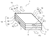
以下、本発明で用いる好ましい形態の流路が設けられてなる積層構造体1の概略構成例を図1に記載する。
Hereinafter, a schematic configuration example of a
<積層構造体>
前記積層構造体1は、例えば前記図1において同一の長方形板状からなる第1プレート(前記図1中の2)と第2プレート(前記図1中の3)と第3プレート(前記図中1の4)が積層されて構成されている。第1プレートには流路が設けられている。また第2プレートには穴が設けられている。第3プレートには流路が設けられている。第1プレートの流路と第2プレートの穴は連通している。第3プレートの流路と第2プレートの穴も連通しており、第2プレートの穴を経由して第1プレートの流路と第3プレートの流路が連通している。そして、図2に示すようにそれらの供給口が積層構造体1の端面1b、側面1d、排出口が端面1cに分散して配置され、それら領域に、液体(ii)と液体(i)を流すためのコネクタ30とジョイント部31とからなる継手部32がそれぞれ連結されている。
<Laminated structure>
The
これらの継手部を介して、前記図1中のF1で示された液体(ii)が端面1bから供給されて、前記図1中のF2で示された液体(i)が側面1dから供給され、液体(i)と液体(ii)が接触して、液体(i)と液体(ii)が、前記図1中F3で示されたように端面1cに排出されるようになっている。
Through these joint portions, the liquid (ii) indicated by F1 in FIG. 1 is supplied from the
積層構造体1の平面視形状は図示のような長方形とは限定されず、正方形状、または端面1b、1c間よりも側面1d間が長い長方形状としてもよいが、以下では簡単のために図示形状に即して、端面1bから端面1cに向かう方向を、積層構造体1の第1プレート、第2プレート、第3プレートの長手方向と称し、側面1dから側面1eに向かう方向を積層構造体1の第1プレート、第2プレート、第3プレートの短手方向と称することにする。
The planar view shape of the
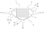
第1プレートは、図3に示すように、一方の面2aに断面凹溝形状の流路5を第1プレートの長手方向に貫通して延し、1本配列したものである。流路5の長さをLとする。断面形状は、幅w0、深さd0とする。
As shown in FIG. 3, the first plate has one
流路5の断面形状は、流体の種類、流量や流路長さLに応じて適宜設定することができるが、幅w0、深さd0は、それぞれ0.1〜500〔mm〕、0.1〜5〔mm〕の範囲に設定している。なお、幅、深さの記載は図面を参照した場合である。
The cross-sectional shape of the
液体(ii)は流路5内に流され、図1ないし図3に矢印で示すように、一方の端面2b側から供給されて他方の端面2c側へ排出される。
The liquid (ii) is caused to flow into the
第2プレートは、図3に示すように、第2プレートを貫通するように穴6が設けられている。穴6の直径はR0とする。穴6の形状は、流体の種類、流量や流路5の形状に応じて設定することができるが、R0は0.1〜500mmの範囲に設定している。図3に示した穴6は第2プレートの真ん中に開いている。
As shown in FIG. 3, the second plate is provided with
第3プレートは、図3に示すように、一方の面4aに断面凹溝形状の流路7を第3プレートの短手方向に延し、第2プレート、第3プレートを積層した際、流路7を穴6と連通する様1本配列したものである。流路7の長さをL‘とする。断面形状は、幅w’0、深さd‘0とする。
As shown in FIG. 3, the third plate has a
流路7の断面形状は、流体の種類、流量、流路長さL‘や流路5の形状、穴6の形状に応じて適宜設定することができるが、幅w’0、深さd‘0は、それぞれ0.1〜500〔mm〕、0.1〜5〔mm〕の範囲に設定している。なお、幅、深さの記載は図面を参照した場合である。
The cross-sectional shape of the
液体(i)は流路7内に流され、流路7に連通した第2プレートの穴6に流され、第1プレートの流路5に流される。液体(i)は流路5において液体(ii)と接触し、図1ないし図3に矢印で示すように、一方の側面1d側から供給されて端面1c側へ排出される。図3に示した穴6の上下に伸びた破線は、流路5、穴6、流路7が連通することを示している。
The liquid (i) is flowed into the
第1プレート、第2プレート、第3プレートは、図1に示すように重ねて積層され、互いに固着、積層されている。 The first plate, the second plate, and the third plate are stacked and stacked as shown in FIG.
そのため、積層構造体1の形態において、流路5は凹溝の開口面が下に積層されるプレートの上面により覆われ両端が開口する長方形断面のトンネル形状とされる。流路7は凹溝の開口面が上に積層されるプレートの下面により覆われ、片端が開口する長方形断面のトンネル形状とされる。
Therefore, in the form of the
このような各第1プレート、第2プレート、第3プレートは、適宜の金属材料を用いることができるが、例えばステンレス鋼板にエッチング加工を施すことにより流路5、穴6、流路7などを形成し、流路面を電解研磨仕上げするなどして製作することができる。
Each of the first plate, the second plate, and the third plate can be made of an appropriate metal material. For example, the
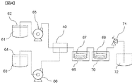
本発明の製造方法で用いる流路が設けられてなる積層構造体を有する装置としては、例えば、図4に記載のある製造装置を例示できる。具体的には、例えば、以下の積層構造体を有する製造装置を例示できる。 As an apparatus having a laminated structure provided with a flow path used in the manufacturing method of the present invention, for example, a manufacturing apparatus shown in FIG. 4 can be exemplified. Specifically, the manufacturing apparatus which has the following laminated structures can be illustrated, for example.
<積層構造体を有する製造装置>
積層構造体は図1に示す構造であり、構造としては、第1プレートと第2プレートと第3プレートが積層している。第1プレートには流路5が形成されおり、第2プレートには穴6が形成されており、また、第3プレートには流路7が形成されている。
<Manufacturing apparatus having a laminated structure>
The laminated structure is the structure shown in FIG. 1, and the first plate, the second plate, and the third plate are laminated as the structure. A
図4に記載のある製造装置に用いられる積層構造体40はドライエッチング加工により流路5が1本形成された第1プレート1枚と同じくエッチング加工により穴6が1個形成された第2プレート1枚と同じくエッチング加工により流路7が1本形成された第3プレートが積層されている。第1プレート2と第2プレート3と第3プレート4の材質はSUS304であり、板厚は1mmである。流路5と流路7の断面寸法はともに幅1.2mm×深さ0.5mmであり、穴6の直径は1.2mmである。
The
図4において、液体(ii)の流体(61)を入れるタンク62(第1のタンク)の流出口とプランジャーポンプ65の流入口とが、液体(ii)の流体が通る配管を介して接続されている。また、液体(i)を入れるタンク64(第2のタンク)の流出口とプランジャーポンプ66の流入口とが、液体(i)の流体(63)が通る配管を介して接続されている。プランジャーポンプ65の流出口及びプランジャーポンプ66の流出口からは、それぞれプランジャーポンプ65またはプランジャーポンプ66を通して液体(ii)の流体又は液体(i)の流体が通る配管が伸びており、これらの配管は積層構造体40の流入口1b、1dに接続されている。
In FIG. 4, the outlet of the tank 62 (first tank) for storing the fluid (61) of the liquid (ii) and the inlet of the
この積層構造体40で液体(i)と液体(ii)とが接触し、不均一な液状状態が形成される。この不均一な液状状態の流体は積層構造体40の流出口1cに接続された配管を通して、チューブ67へと移動する。チューブ67は温調装置を備えたオイルバス68に浸漬されている。このチューブ内を移動していくことによりラジカル重合体が重合反応する。その後、チューブ流出口に接続された配管を通してチューブ69へと移動する。チューブ69は水槽70に浸漬されている。
In this
チューブ69の流入口へと移動した重合反応物を含有する流体はチューブ69中を移動しながら冷却され、チューブ69の流出口へと到達する。流出口に接続された配管を通してチューブ69から流体は排出され、排圧弁71を通して受け容器72へと排出される。
The fluid containing the polymerization reactant that has moved to the inlet of the
また、マイクロミキサーとして市販されている微小構造体でも、液体(i)と液体(ii)を接触させて不均一な液状状態、すなわちスラグ流を形成できるマイクロミキサーであれば、前記積層構造体のように用いることが可能である。例えばインターディジタルチャンネル構造を備えるマイクロリアクター、インスティチュート・フュール・マイクロテクニック・マインツ(IMM)社製シングルミキサーおよびキャタピラーミキサー;ミクログラス社製ミクログラスリアクター;CPCシステムス社製サイトス;山武社製YM−1、YM−2型ミキサー;島津GLC社製ミキシングティーおよびティー(T字コネクタ);マイクロ化学技研社製IMTチップリアクター;東レエンジニアリング開発品マイクロ・ハイ・ミキサー等が挙げられ、液体(i)と液体(ii)を接触させて不均一な液状状態、すなわちスラグ流を形成できる工夫を施せば、いずれも本発明で使用することができる。 Further, even in a microstructure that is commercially available as a micromixer, if the micromixer can form a non-uniform liquid state, that is, a slag flow, by contacting the liquid (i) and the liquid (ii), Can be used. For example, a microreactor equipped with an interdigital channel structure, a single mixer and a caterpillar mixer manufactured by Institute, Fleet, Microtechnique Mainz (IMM); a microglass reactor manufactured by Microglass; a cytos manufactured by CPC Systems; a YM manufactured by Yamatake -1, YM-2 type mixer; Shimadzu GLC's mixing tee and tee (T-shaped connector); Micro Chemical Engineering Co., Ltd. IMT chip reactor; Any liquid can be used in the present invention if it is devised so that a non-uniform liquid state, that is, a slag flow can be formed by bringing the liquid (ii) into contact with each other.
本発明においてラジカル重合体は、マイクロリアクター中で、ラジカル重合開始剤とラジカル重合性単量体とを含有する流体と、該流体が混和しない液体からなる流体とを、交互に流通するように反応菅に導入して、反応させる方法であって、さらに詳しくは、
少なくとも2つの流路(I)と流路(II)とが合流して、1つの流路(III)を形成している反応装置であって、
前記流路(I)にラジカル重合性開始剤とラジカル重合性単量体とを含有する液体(i)と、前記液体(i)と混和しない液体(ii)とを、前記流路(I)の流速(V1)と前記流路(II)の流速(V2)とが〔V1≦V2〕となるように供給し、
且つ、前記流路(III)を液体(i)と液体(ii)が通過する間に、液体(i)中のラジカル重合性単量体の重合反応を行なうことを特徴とするラジカル重合体の製造方法である。
In the present invention, the radical polymer is reacted in a microreactor so that a fluid containing a radical polymerization initiator and a radical polymerizable monomer and a fluid composed of a liquid in which the fluid is immiscible alternately flow. It is a method of introducing into a jar and reacting.
A reaction apparatus in which at least two flow paths (I) and flow paths (II) merge to form one flow path (III),
A liquid (i) containing a radical polymerizable initiator and a radical polymerizable monomer in the flow path (I) and a liquid (ii) immiscible with the liquid (i) are converted into the flow path (I). The flow rate (V 1 ) and the flow rate (V 2 ) of the channel (II) are supplied so that [V 1 ≦ V 2 ],
And a radical polymerization monomer in the liquid (i) undergoes a polymerization reaction while the liquid (i) and the liquid (ii) pass through the channel (III). It is a manufacturing method.
本発明において使用されるラジカル重合開始剤としては特に制限はなく、従来ラジカル重合において使用されている種々のラジカル重合開始剤の中から、原料のラジカル重合性単量体や重合溶媒の種類などに応じて適宣選択して用いることができる。このようなラジカル重合開始剤としては、例えば有機過酸化物、アゾ化合物、ジスルフィド化合物、レドックス系開始剤、過硫酸塩などが挙げられる。一般的には、重合溶媒が水性媒体である場合には、水溶性有機過酸化物、水溶性アゾ化合物、レドックス系開始剤、過硫酸塩などが好ましく用いられ、重合溶媒が有機溶媒である場合には、油溶性有機過酸化物及び油溶性アゾ化合物などが好ましく用いられる。 The radical polymerization initiator used in the present invention is not particularly limited, and various radical polymerization initiators conventionally used in radical polymerization can be used depending on the type of raw material radical polymerizable monomer and polymerization solvent. It can be selected and used accordingly. Examples of such radical polymerization initiators include organic peroxides, azo compounds, disulfide compounds, redox initiators, persulfates, and the like. In general, when the polymerization solvent is an aqueous medium, water-soluble organic peroxides, water-soluble azo compounds, redox initiators, persulfates, and the like are preferably used, and the polymerization solvent is an organic solvent. For this, oil-soluble organic peroxides and oil-soluble azo compounds are preferably used.
上記水溶性有機過酸化物の例としては、t−ブチルヒドロペルオキシド、クメンヒドロペルオキシド、ジイソプロピルベンゼンヒドロペルオキシド、p−メンタンヒドロペルオキシド、2,5−ジメチルヘキサン−2,5−ジヒドロペルオキシド、1,1,3,3−テトラメチルヒドロペルオキシドなどが挙げられる。また、水溶性アゾ化合物の例としては、2,2’−ジアミジニル−2,2’−アゾプロパン・一塩酸塩、2,2’−ジアミジニル−2,2’−アゾブタン・一塩酸塩、2,2’−ジアミジニル−2,2’−アゾペンタン・一塩酸塩、2,2’−アゾビス(2−メチル−4−ジエチルアミノ)ブチロニトリル・塩酸塩などが挙げられる。 Examples of the water-soluble organic peroxide include t-butyl hydroperoxide, cumene hydroperoxide, diisopropylbenzene hydroperoxide, p-menthane hydroperoxide, 2,5-dimethylhexane-2,5-dihydroperoxide, 1,1 , 3,3-tetramethyl hydroperoxide and the like. Examples of water-soluble azo compounds include 2,2′-diamidinyl-2,2′-azopropane monohydrochloride, 2,2′-diamidinyl-2,2′-azobutane monohydrochloride, 2,2 Examples include '-diamidinyl-2,2'-azopentane monohydrochloride and 2,2'-azobis (2-methyl-4-diethylamino) butyronitrile hydrochloride.
レドックス系開始剤としては、例えば過酸化水素と還元剤との組合わせなどを挙げることができる。この場合、還元剤としては、二価の鉄イオンや銅イオン、亜鉛イオン、コバルトイオン、バナジウムイオンなどの金属イオン、アスコルビン酸、還元糖などが用いられる。過硫酸塩としては、例えば過硫酸アンモニウム、過硫酸カリウムなどが挙げられる。 Examples of redox initiators include a combination of hydrogen peroxide and a reducing agent. In this case, as the reducing agent, divalent iron ions, copper ions, zinc ions, cobalt ions, vanadium ions and other metal ions, ascorbic acid, reducing sugars and the like are used. Examples of the persulfate include ammonium persulfate and potassium persulfate.
一方、油溶性有機過酸化物の例としては、アセチルシクロヘキシルスルホニルパーオキサイド、イソブチリルパーオキサイド、ジイソプロピルパーオキシジカーボネート、ジ−2−エチルヘキシルパーオキシジカーボネート、2,4−ジクロロベンゾイルパーオキサイド、t−ブチルパーオキシビバレート、3,5,5−トリメチルヘキサノニルパーオキサイド、オクタノイルパーオキサイド、デカノイルパーオキサイド、ラウロイルパーオキサイド、ステアロイルパーオキサイド、プロピオニトリルパーオキサイド、サクシニックアシッドパーオキサイド、アセチルパーオキサイド、t−ブチルパーオキシ−2−エチルヘキサノエート、ベンゾイルパーオキサイド、パラクロロベンゾイルパーオキサイド、t−ブチルパーオキシイソブチレート、t−ブチルパーオキシマレイックアシッド、t−ブチルパーオキシラウレート、シクロヘキサノンパーオキサイド、t−ブチルパーオキシイソプロピルカーボネート、2,5−ジメチル−2,5−ジベンゾイルパーオキシヘキサン、t−ブチルパーオキシアセテート、t−ブチルパーオキシベンゾエート、ジイソブチルジパーオキシフタレート、メチルエチルケトンパーオキサイド、ジクミルパーオキサイド、2,5−ジメチル−2,5−ジt−ブチルパーオキシヘキサン、t−ブチルクミルパーオキサイド、t−ブチルヒドロパーオキサイド、ジt−ブチルパーオキサイド、ジイソプロピルベンゼンヒドロパーオキサイド、パラメンタンヒドロパーオキサイド、ピナンヒドロパーオキサイド、2,5−ジメチルヘキサン−2,5−ジヒドロパーオキサイド、クメンパーオキサイドなどが挙げられる。また、油溶性アゾ化合物の例としては、2,2’−アゾビスイソブチロニトリル、1,1’−アゾビスシクロヘキサン1−カーボニトリル、2,2’−アゾビス−4−メトキシ−2,4−ジメチルバレロニトリル、2,2’−アゾビス−2,4−ジメチルバレロニトリル、ジメチル−2,2’−アゾビス(2−メチルプロピオネート)、1,1’−アゾビス(1−アセトキシ−1−フェニルエタン)、2,2’−アゾビス(4−メトキシ−2,4−ジメチルバレロニトリル)などが挙げられる。これらの油溶性ラジカル重合開始剤は一種を単独で用いてもよく、二種以上を組み合わせて用いてもよい。 On the other hand, examples of oil-soluble organic peroxides include acetylcyclohexylsulfonyl peroxide, isobutyryl peroxide, diisopropyl peroxydicarbonate, di-2-ethylhexyl peroxydicarbonate, 2,4-dichlorobenzoyl peroxide, t -Butylperoxybivalate, 3,5,5-trimethylhexanonyl peroxide, octanoyl peroxide, decanoyl peroxide, lauroyl peroxide, stearoyl peroxide, propionitrile peroxide, succinic acid peroxide, acetyl Peroxide, t-butylperoxy-2-ethylhexanoate, benzoyl peroxide, parachlorobenzoyl peroxide, t-butylperoxyisobutylene T-butyl peroxymaleic acid, t-butyl peroxylaurate, cyclohexanone peroxide, t-butyl peroxyisopropyl carbonate, 2,5-dimethyl-2,5-dibenzoylperoxyhexane, t-butyl Peroxyacetate, t-butylperoxybenzoate, diisobutyldiperoxyphthalate, methyl ethyl ketone peroxide, dicumyl peroxide, 2,5-dimethyl-2,5-di-t-butylperoxyhexane, t-butylcumyl peroxide , T-butyl hydroperoxide, di-t-butyl peroxide, diisopropylbenzene hydroperoxide, paramentane hydroperoxide, pinane hydroperoxide, 2,5-dimethylhexane-2,5-di Mud peroxide, such as cumene peroxide. Examples of oil-soluble azo compounds include 2,2′-azobisisobutyronitrile, 1,1′-azobiscyclohexane 1-carbonitrile, 2,2′-azobis-4-methoxy-2,4. -Dimethylvaleronitrile, 2,2'-azobis-2,4-dimethylvaleronitrile, dimethyl-2,2'-azobis (2-methylpropionate), 1,1'-azobis (1-acetoxy-1- Phenylethane), 2,2′-azobis (4-methoxy-2,4-dimethylvaleronitrile), and the like. These oil-soluble radical polymerization initiators may be used alone or in combination of two or more.
本発明においては、前記ラジカル重合開始剤の使用量は、目的とするラジカル重合体の分子量などに応じて適宜選定されるため一概に使用量を限定することはできないが、通常ラジカル重合性単量体100重量部に対し、好ましくは0.001〜20重量部、さらに好ましくは0.01〜10重量部である。 In the present invention, the amount of the radical polymerization initiator used is appropriately selected according to the molecular weight of the target radical polymer and the like, and thus the amount cannot be generally limited. Preferably it is 0.001-20 weight part with respect to 100 weight part of a body, More preferably, it is 0.01-10 weight part.
また、本発明におけるラジカル重合体の製造方法においては光重合開始剤からなるラジカル重合開始剤を使用することもできる。光重合させるための流路(III)としては、紫外光を透過し得る流路であれば用いることが可能であり、ガラス、石英、カーボンといった材質のチューブのほか、流路の一部が紫外光を透過するガラス、石英、カーボンといった材質からなる流路であってもよい。 Moreover, in the manufacturing method of the radical polymer in this invention, the radical polymerization initiator which consists of a photoinitiator can also be used. As the flow path (III) for photopolymerization, any flow path that can transmit ultraviolet light can be used. In addition to a tube made of glass, quartz, or carbon, a part of the flow path is made of ultraviolet light. The flow path may be made of a material such as glass, quartz, or carbon that transmits light.
光重合させるための光重合開始剤としては、例えば、ベンゾイン誘導体、ベンジルケタール類、α−ヒドロキシアセトフェノン類、α−アミノアセトフェノン類、アシルフォスフィンオキサイド類、o−アシルオキシム類等が挙げられる。また、光重合開始剤は、種々の製品が市販されている。具体例としては、ベンゾフェノン/アミン、ミヒラーケトン/ベンゾフェノン、チオキサントン/アミンなどの組み合わせ(商品名:イルガキュアやダロキュアなど、チバガイギー社製)等が挙げられる。 Examples of the photopolymerization initiator for photopolymerization include benzoin derivatives, benzyl ketals, α-hydroxyacetophenones, α-aminoacetophenones, acylphosphine oxides, o-acyloximes and the like. Moreover, various products are marketed as a photoinitiator. Specific examples include combinations of benzophenone / amine, Michlerketone / benzophenone, thioxanthone / amine, etc. (trade names: Irgacure, Darocur, etc., manufactured by Ciba Geigy).
上記光重合開始剤の含有量は、任意の適切な値に設定され得る。上記光硬化性モノマー100重量部に対して、好ましくは0.1〜7重量部、さらに好ましくは1〜6重量部、特に好ましくは4〜5重量部である。 The content of the photopolymerization initiator can be set to any appropriate value. Preferably it is 0.1-7 weight part with respect to 100 weight part of said photocurable monomers, More preferably, it is 1-6 weight part, Especially preferably, it is 4-5 weight part.
紫外光照射手段の具体例としては、超高圧水銀ランプ、フラッシュUVランプ、高圧水銀ランプ、低圧水銀ランプ、ディープUVランプ、キセノンランプ、キセノンフラッシュランプ、メタルハライドランプ、発光ダイオード等が挙げられる。 Specific examples of the ultraviolet light irradiation means include an ultra high pressure mercury lamp, a flash UV lamp, a high pressure mercury lamp, a low pressure mercury lamp, a deep UV lamp, a xenon lamp, a xenon flash lamp, a metal halide lamp, a light emitting diode, and the like.
上記紫外光照射手段の設置位置は、少なくとも光重合させることが可能であれば、特に限定されない。 The installation position of the ultraviolet light irradiation means is not particularly limited as long as at least photopolymerization is possible.
本発明の製造方法で使用されるラジカル重合性単量体としては、ラジカル重合性不飽和基を持つ化合物であれば特に限定されるものではないが、例えば、メチル(メタ)アクリレート、エチル(メタ)アクリレート、ブチル(メタ)アクリレート、ヘキシル(メタ)アクリレート、シクロヘキシル(メタ)アクリレート、2−エチルヘキシル(メタ)アクリレート、オクチル(メタ)アクリレート、ノニル(メタ)アクリレート、ラウリル(メタ)アクリレート、ステアリル(メタ)アクリレート等の炭素数1〜30のアルキル(メタ)アクリレート類のアクリル系不飽和単量体; The radical polymerizable monomer used in the production method of the present invention is not particularly limited as long as it is a compound having a radical polymerizable unsaturated group. For example, methyl (meth) acrylate, ethyl (meta ) Acrylate, butyl (meth) acrylate, hexyl (meth) acrylate, cyclohexyl (meth) acrylate, 2-ethylhexyl (meth) acrylate, octyl (meth) acrylate, nonyl (meth) acrylate, lauryl (meth) acrylate, stearyl (meth) ) Acrylic unsaturated monomers of C1-C30 alkyl (meth) acrylates such as acrylates;
(メタ)アクリル酸、イタコン酸またはそのモノエステル、マレイン酸またはそのモノエステル、フマル酸またはそのモノエステル、イタコン酸またはそのモノエステル、クロトン酸、p−ビニル安息香酸などのカルボン酸基含有不飽和単量体およびこれらの塩;2−(メタ)アクリルアミド−2−メチルプロパンスルホン酸、ビニルスルホン酸、スチレンスルホン酸、(メタ)アリルスルホン酸、スルホエチル(メタ)アクリレート、スルホプロピル(メタ)アクリレート、α−メチルスチレンスルホン酸などのスルホン酸基含有不飽和単量体およびこれらの塩; Carboxylic acid group-containing unsaturated compounds such as (meth) acrylic acid, itaconic acid or its monoester, maleic acid or its monoester, fumaric acid or its monoester, itaconic acid or its monoester, crotonic acid, p-vinylbenzoic acid Monomers and salts thereof; 2- (meth) acrylamide-2-methylpropanesulfonic acid, vinylsulfonic acid, styrenesulfonic acid, (meth) allylsulfonic acid, sulfoethyl (meth) acrylate, sulfopropyl (meth) acrylate, sulfonic acid group-containing unsaturated monomers such as α-methylstyrene sulfonic acid and salts thereof;
ジメチルアミノエチル(メタ)アクリレート、ジエチルアミノエチル(メタ)アクリレート、ビニルピロリドン、N−メチルビニルピリジウムクロライド、(メタ)アリルトリエチルアンモニウムクロライド、2−ヒドロキシ−3−(メタ)アクリロイルオキシプロピルトリメチルアンモニウムクロライド等の第3級または第4級アミノ基含有不飽和単量体;ヒドロキシエチル(メタ)アクリレート、ヒドロキシプロピル(メタ)アクリレート、ポリエチレングリコールモノ(メタ)アクリレート等の水酸基含有不飽和単量体;(メタ)アクリルアミド、N−ヒドロキシアルキル(メタ)アクリルアミド、N−アルキル(メタ)アクリルアミド、N、N−ジアルキル(メタ)アクリルアミド、ビニルラクタム類などアミド基含有不飽和単量体; Dimethylaminoethyl (meth) acrylate, diethylaminoethyl (meth) acrylate, vinylpyrrolidone, N-methylvinylpyridium chloride, (meth) allyltriethylammonium chloride, 2-hydroxy-3- (meth) acryloyloxypropyltrimethylammonium chloride, etc. A tertiary or quaternary amino group-containing unsaturated monomer; a hydroxyl-containing unsaturated monomer such as hydroxyethyl (meth) acrylate, hydroxypropyl (meth) acrylate, or polyethylene glycol mono (meth) acrylate; ) Amide-containing unsaturated monomers such as acrylamide, N-hydroxyalkyl (meth) acrylamide, N-alkyl (meth) acrylamide, N, N-dialkyl (meth) acrylamide, vinyl lactams
マレイン酸、フマル酸、イタコン酸等の不飽和二塩基酸のジエステル類、スチレン、p−メチルスチレン、α−メチルスチレン、p−クロロスチレン、クロルメチルスチレン、ビニルトルエン等の芳香族不飽和単量体、アクリロニトリル、メタクリロニトリル等のニトリル系不飽和単量体;ブタジエン、イソプレン等の共役ジオレフィン不飽和単量体;ジビニルベンゼン、エチレングリコールジアクリレート、エチレングリコールジメタクリレート、ジエチレングリコールジメタクリレート、メタクリル酸アリル、フタル酸ジアリル、トリメチロールプロパントリアクリレート、グリセリンジアリルエーテル、ポリエチレングリコールジメタクリレート、ポリエチレングリコールジアクリレート等の多官能不飽和単量体;エチレン、プロピレン、イソブチレン等のビニル系不飽和単量体;酢酸ビニル、プロピオン酸ビニル、オクチルビニルエステル、ベオバ9、ベオバ10、ベオバ11〔ベオバ:シェルケミカルカンパニー(株)商標〕等のビニルエステル不飽和単量体;エチルビニルエーテル、プロピルビニルエーテル、ブチルビニルエーテル、シクロヘキシルビニルエーテル等のビニルエーテル不飽和単量体;エチルアリルエーテル等のアリルエーテル不飽和単量体;塩化ビニル、臭化ビニル、塩化ビニリデン、フッ化ビニリデン、クロロトリフルオロエチレン、テトラフルオロエチレン、ヘキサフルオロプロピレン、ペンタフルオロプロピレン、パーフルオロ(プロピルビニルエーテル)、パーフルオロアルキルアクリレート、フルオロメタクリレート等のハロゲン含有不飽和単量体等;
Unsaturated dibasic acid diesters such as maleic acid, fumaric acid, itaconic acid, aromatic unsaturated monomers such as styrene, p-methylstyrene, α-methylstyrene, p-chlorostyrene, chloromethylstyrene, vinyltoluene Nitrile unsaturated monomers such as acrylonitrile and methacrylonitrile; conjugated diolefin unsaturated monomers such as butadiene and isoprene; divinylbenzene, ethylene glycol diacrylate, ethylene glycol dimethacrylate, diethylene glycol dimethacrylate, methacrylic acid Polyfunctional unsaturated monomers such as allyl, diallyl phthalate, trimethylolpropane triacrylate, glyceryl diallyl ether, polyethylene glycol dimethacrylate, polyethylene glycol diacrylate; ethylene, propylene Vinyl ester unsaturated monomers such as vinyl acetate, vinyl propionate, octyl vinyl ester, Veova 9,
(メタ)アクリル酸グリシジル、メタクリル酸グリシジルなどのエポキシ基含有不飽和単量体;ビニルトリクロロシラン、ビニルトリエトキシシラン、ビニルトリス(β−メトキシエトキシ)シラン、γ−メタクリロキシプロピルトリメトキシシラン等のビニルシラン系不飽和単量体;アクロレイン、ダイアセトンアクリルアミド、ビニルメチルケトン、ビニルブチルケトン、ダイアセトンアクリレート、アセトニトリルアクリレート、アセトアセトキシエチル(メタ)アクリレート、ビニルアセトフェノン、ビニルベンゾフェノン等のカルボニル基含有不飽和単量体等が挙げられる。 Epoxy group-containing unsaturated monomers such as glycidyl acrylate and glycidyl methacrylate; vinyl silanes such as vinyltrichlorosilane, vinyltriethoxysilane, vinyltris (β-methoxyethoxy) silane, and γ-methacryloxypropyltrimethoxysilane Unsaturated monomers containing carbonyl groups such as acrolein, diacetone acrylamide, vinyl methyl ketone, vinyl butyl ketone, diacetone acrylate, acetonitrile acrylate, acetoacetoxyethyl (meth) acrylate, vinyl acetophenone, vinyl benzophenone Examples include the body.
また、ラジカル重合単量体としてフッ素化アルキル基含有エチレン性不飽和単量体を用いることも可能である。 It is also possible to use a fluorinated alkyl group-containing ethylenically unsaturated monomer as the radical polymerization monomer.
フッ素化アルキル基含有エチレン性不飽和単量体は、フッ素化アルキル基とエチレン性不飽和基を有する化合物であれば制限なく用いることができる。 The fluorinated alkyl group-containing ethylenically unsaturated monomer can be used without limitation as long as it is a compound having a fluorinated alkyl group and an ethylenically unsaturated group.
なお、本発明に用いるフッ素化アルキル基を含有する重合性単量体において、フッ素化アルキル基とは、アルキル基中の全ての水素原子がフッ素原子に置換されたもの(パーフルオロアルキル基)と、アルキル基中の一部の水素原子がフッ素原子で置換されたもの〔例えば、−(CF2)6H等〕との総称であり、直鎖状でも分岐状であっても良い。更に、該フッ素化アルキル基中に酸素原子を含むもの〔例えば−OCF2CF2(OCF(CF3)CF2)2CF2CF3、−(OCF2CF2)8−等〕も本定義中に含めるものとする。 In the polymerizable monomer containing a fluorinated alkyl group used in the present invention, the fluorinated alkyl group is one in which all hydrogen atoms in the alkyl group are substituted with fluorine atoms (perfluoroalkyl group). , Is a generic name for those in which some hydrogen atoms in the alkyl group are substituted with fluorine atoms (for example, — (CF 2 ) 6 H and the like), and may be linear or branched. Further, those containing an oxygen atom in the fluorinated alkyl group (for example, —OCF 2 CF 2 (OCF (CF 3 ) CF 2 ) 2 CF 2 CF 3 , — (OCF 2 CF 2 ) 8 — etc.)) are also defined in this definition. Shall be included.
Rfとしては、例えば、−C4F9、−C7F15、−C8F17、−(CF2)4H、−(CF2)6CF(CF3)2、−(OCF2CF2)4OCF2CF3、−(OCF2CF(CF3))3C3F7等が挙げられる。
The R f, for example, -C 4 F 9, -C 7 F 15, -C 8 F 17, - (CF 2) 4 H, - (CF 2) 6 CF (CF 3) 2, - (
フッ素化アルキル基含有エチレン性不飽和単量体の具体例として以下の如きものが挙げられる。
a−1 :CH2=CHCOOCH2CH2C8F17
a−2 :CH2=C(CH3)COOCH2CH2C8F17
a−3 :CH2=CHCOOCH2CH2C12F25
a−4 :CH2=CHCOOCH2CH2C6F13
a−5 :CH2=CHCOOCH2CH2C4F9
a−6 :CH2=CFCOOCH2CH2C6F13
a−7 :CH2=CHCOOCH2CF3
a−8 :CH2=C(CH3)COOCH2CF(CF3)2
a−9 :CH2=C(CH3)COOCH2CFHCF3
a−10:CH2=CHCOOCH2(CF2)6H
a−11:CH2=CHCOOCH2CH(OH)CH2C8F17
a−12:CH2=CHCOOCH2CH2N(C3H7)SO2C8F17
a−13:CH2=CHCOOCH2CH2N(C2H5)COC7F15
a−14:CH2=CHCOOC2H4(CF(CF3)OCF2)3C2F5
a−15:CH2=CHCOOCH2(CF(CF3)OCF2)2C2F5
a−16:CH2=CHCOOCH2CH2NHSO2C4F9
a−17:CH2=CHCOOCH2CH2N(CH3)SO2C4F9
a−18:CH2=CHCOOCH2CH2N(C2H5)SO2C4F9
a−19:CH2=CHCOOCH2CH2N(C3H7)SO2C4F9
a−20:CH2=C(CH3)COOCH2CH2N(CH3)SO2C4F9
Specific examples of the fluorinated alkyl group-containing ethylenically unsaturated monomer include the following.
a-1: CH 2 = CHCOOCH 2 CH 2 C 8 F 17
a-2: CH 2 = C (CH 3)
a-3: CH 2 = CHCOOCH 2 CH 2 C 12 F 25
a-4: CH 2 = CHCOOCH 2 CH 2 C 6 F 13
a-5: CH 2 = CHCOOCH 2 CH 2 C 4 F 9
a-6: CH 2 = CFCOOCH 2 CH 2 C 6 F 13
a-7: CH 2 = CHCOOCH 2
a-8: CH 2 = C (CH 3)
a-9: CH 2 = C (CH 3)
a-10: CH 2 = CHCOOCH 2 (CF 2) 6 H
a-11: CH 2 = CHCOOCH 2 CH (OH) CH 2 C 8 F 17
a-12: CH 2 = CHCOOCH 2 CH 2 N (C 3 H 7) SO 2 C 8 F 17
a-13: CH 2 = CHCOOCH 2 CH 2 N (C 2 H 5) COC 7 F 15
a-14: CH 2 = CHCOOC 2 H 4 (CF (CF 3) OCF 2) 3 C 2
a-15: CH 2 = CHCOOCH 2 (CF (CF 3) OCF 2) 2 C 2
a-16: CH 2 = CHCOOCH 2
a-17: CH 2 = CHCOOCH 2 CH 2 N (CH 3) SO 2 C 4 F 9
a-18: CH 2 = CHCOOCH 2 CH 2 N (C 2 H 5) SO 2 C 4 F 9
a-19: CH 2 = CHCOOCH 2 CH 2 N (C 3 H 7) SO 2 C 4 F 9
a-20: CH 2 = C (CH 3)

本発明においては、必要に応じ重合溶媒を用いることができる。この重合溶媒は使用するラジカル重合性単量体の種類に応じて適宜選択して用いられる。有機溶媒としては、トルエン、キシレン、エチルベンゼン、テトラリン等の芳香族炭化水素系溶剤;n−ヘキサン、n−ヘプタン、ミネラルスピリット、シクロヘキサン等の脂肪族または脂環式炭化水素系溶剤;塩化メチル、臭化メチル、ヨウ化メチル、メチレンジクロライド、四塩化炭素、トリクロロエチレン、パークロロエチレンなどのハロゲン系溶剤;酢酸エチル、酢酸ブチル、プロピオン酸メチル、プロピオン酸エチル、メトキシブチルアセテート、メチルセロソルブアセテート、エチルセロソルブアセテートなどのエステル系またはエステルエーテル系溶剤;ジエチルエーテル、テトラヒドロフラン、ジオキサン、エチルセロソルブ、ブチルセロソルブ、プロピレングリコールモノメチルエーテルなどのエーテル系溶剤;アセトン、メチルエチルケトン、メチルイソブチルケトン、ジ−n−ブチルケトン、シクロヘキサノンなどのケトン系溶剤;メタノール、エタノール、n−プロパノール、イソプロパノール、n−ブタノール、イソブタノール、t−ブタノール、2−エチルヘキシルアルコール、ベンジルアルコールなどのアルコール系溶剤;ジメチルホルムアミド、ジメチルアセトアミドなどのアミド系溶剤;ジメチルスルホキシドなどのスルホキシド系溶剤、N−メチルピロリドンなどの複素環式化合物系溶剤、ならびにこれらの2種以上の混合溶剤が挙げられる。 In the present invention, a polymerization solvent can be used as necessary. This polymerization solvent is appropriately selected according to the type of radical polymerizable monomer to be used. Examples of organic solvents include aromatic hydrocarbon solvents such as toluene, xylene, ethylbenzene, and tetralin; aliphatic or alicyclic hydrocarbon solvents such as n-hexane, n-heptane, mineral spirit, and cyclohexane; methyl chloride, odor Halogenated solvents such as methyl iodide, methyl iodide, methylene dichloride, carbon tetrachloride, trichloroethylene, perchloroethylene; ethyl acetate, butyl acetate, methyl propionate, ethyl propionate, methoxybutyl acetate, methyl cellosolve acetate, ethyl cellosolve acetate Ester or ester ether solvents such as; ether solvents such as diethyl ether, tetrahydrofuran, dioxane, ethyl cellosolve, butyl cellosolve, propylene glycol monomethyl ether; acetone Ketone solvents such as methyl ethyl ketone, methyl isobutyl ketone, di-n-butyl ketone and cyclohexanone; alcohols such as methanol, ethanol, n-propanol, isopropanol, n-butanol, isobutanol, t-butanol, 2-ethylhexyl alcohol and benzyl alcohol Examples thereof include amide solvents such as dimethylformamide and dimethylacetamide; sulfoxide solvents such as dimethyl sulfoxide, heterocyclic compound solvents such as N-methylpyrrolidone, and mixed solvents of two or more of these.
以下本発明を実施例によって更に詳細に説明する。また、文中に「部」「%」とあるのは、重量基準を示すものである。 Hereinafter, the present invention will be described in more detail with reference to examples. Also, “parts” and “%” in the text indicate weight standards.
<収率の測定>
合成した樹脂を1g計量し、トルエン/メタノール混合液(7/3重量比)を5g加えて攪拌し、120℃の乾燥機に1時間入れ、含有する有機溶媒を除去した。有機溶媒除去後の重量から樹脂の固形分を計算した。合成に使用したラジカル重合開始剤とラジカル重合性単量体の濃度と算出された固形分の値から収率を計算した。
<Measurement of yield>
1 g of the synthesized resin was weighed, 5 g of a toluene / methanol mixture (7/3 weight ratio) was added and stirred, and placed in a dryer at 120 ° C. for 1 hour to remove the organic solvent contained. The solid content of the resin was calculated from the weight after removal of the organic solvent. The yield was calculated from the concentration of the radical polymerization initiator and radical polymerizable monomer used in the synthesis and the calculated solid content.
<残存モノマー量の測定方法>
ラジカル重合体に含まれる残存モノマー量はガスクロマトグラフ質量分析計GC−MS−QP5050A(株式会社島津製作所製)を用いて行った。ラジカル重合体をアセトン溶解し、15mg/mlの濃度に調整し測定を行った。使用したラジカル重合性単量体の各濃度を算出して合計し、ラジカル重合体に含まれる残存モノマー量とした。
<Measurement method of residual monomer amount>
The amount of residual monomer contained in the radical polymer was measured using a gas chromatograph mass spectrometer GC-MS-QP5050A (manufactured by Shimadzu Corporation). The radical polymer was dissolved in acetone and adjusted to a concentration of 15 mg / ml for measurement. Each concentration of the radical polymerizable monomer used was calculated and totaled to obtain the amount of residual monomer contained in the radical polymer.
<重量平均分子量分布の測定>
合成した樹脂の分子量分布の測定は、HLC8220(分子量測定装置、東ソー)にて測定し、標準ポリスチレン換算で重量平均分子量を計算した。
<Measurement of weight average molecular weight distribution>
The molecular weight distribution of the synthesized resin was measured with HLC8220 (molecular weight measuring device, Tosoh), and the weight average molecular weight was calculated in terms of standard polystyrene.
(実施例1)
シリンジポンプのシリンジの出口に圧力計、安全弁、フィルター、逆止弁を介し内径2.17mmのチューブの接続を行った。その後内径1.09mmのチューブに接続した(微小流路(I))。このように接続したシリンジポンプをもう一台作製した(微小流路(II))。それぞれのチューブをT−コネクター(ユニオンティー)で接続して合流する合流点を作製し、合流後流体が内径1.09mmのチューブに排出されるようにした。その後内径2.17mm、長さ30mのチューブに接続してチューブを延長し、恒温槽に浸し、加温できるようにした(微小流路(III))。同様に微小流路(II)も恒温槽に浸し、加温できるようにした。更にそのチューブの先に内径2.17mm、長さ1mのチューブを接続した。このチューブは水に浸して冷却できるようにした。最後に背圧弁を接続し、吐出された反応混合物を受け容器にて受け取ることができるようにした。
メタクリル酸メチル(MMA)80g、メタクリル酸ブチル(BMA)120g、トルエン100g、n−ブタノール100g、t−ブチルパーオキシ−2−エチルヘキサノエート 6gをよく混合して調製した(アクリルモノマー液1)。このアクリルモノマー液1をシリンジポンプに仕込んだ。もう一方のシリンジポンプにイオン交換水を仕込んだ。アクリルモノマー液1を流速2g/分にて微小流路(I)に導入し、イオン交換水を6g/分にて微小流路(II)に導入して、混合液の流速が8g/分となるように微小流路(III)に導入した。恒温槽の温度は110℃とした。吐出された液を受け容器に受け取ることにより、ラジカル重合体の製造を行った。このとき、管内の圧力は1.0MPaに調整した。得られたラジカル重合体の分析を行ったところ、固形分46.1%、収率90.9%、残存モノマー68655ppm、重量平均分子量(Mw)は13481であった。
Example 1
A tube having an inner diameter of 2.17 mm was connected to the outlet of the syringe of the syringe pump via a pressure gauge, a safety valve, a filter, and a check valve. Thereafter, it was connected to a tube having an inner diameter of 1.09 mm (microchannel (I)). Another syringe pump connected in this way was produced (microchannel (II)). Each tube was connected by a T-connector (union tee) to create a merge point, and after the merge, the fluid was discharged to a tube having an inner diameter of 1.09 mm. Thereafter, the tube was connected to a tube having an inner diameter of 2.17 mm and a length of 30 m, and the tube was extended and immersed in a thermostatic bath so as to be heated (microchannel (III)). Similarly, the microchannel (II) was immersed in a thermostatic chamber so that it could be heated. Further, a tube having an inner diameter of 2.17 mm and a length of 1 m was connected to the tip of the tube. This tube was immersed in water so that it could be cooled. Finally, a back pressure valve was connected so that the discharged reaction mixture could be received in a container.
Prepared by mixing 80 g of methyl methacrylate (MMA), 120 g of butyl methacrylate (BMA), 100 g of toluene, 100 g of n-butanol, and 6 g of t-butylperoxy-2-ethylhexanoate (acrylic monomer solution 1) . This
(実施例2)
アクリルモノマー液1を調製し、シリンジポンプに仕込んだ。もう一方のシリンジポンプにイオン交換水を仕込んだ。アクリルモノマー液1を流速2g/分にて微小流路(I)に導入し、イオン交換水を6g/分にて微小流路(II)に導入して、混合液の流速が8g/分となるように微小流路(III)に導入した。恒温槽の温度を120℃とした他は実施例1と同様の操作によりラジカル重合体の製造を行った。
(Example 2)
得られたラジカル重合体の分析を行ったところ、固形分50.7%、収率99.9%、残存モノマー73938ppm、Mw10737であった。 When the obtained radical polymer was analyzed, the solid content was 50.7%, the yield was 99.9%, the residual monomer was 73938 ppm, and Mw10737.
(実施例3)
アクリルモノマー液1を調製し、シリンジポンプに仕込んだ。もう一方のシリンジポンプにイオン交換水を仕込んだ。アクリルモノマー液1を流速2g/分にて微小流路(I)に導入し、イオン交換水を6g/分にて微小流路(II)に導入して、混合液の流速が8g/分となるように微小流路(III)に導入した。恒温槽の温度を130℃とした他は実施例1と同様の操作によりラジカル重合体の製造を行った。
(Example 3)
得られたラジカル重合体の分析を行ったところ、固形分44.2%、収率87.1%、残存モノマー120545ppm、Mw9220であった。 When the obtained radical polymer was analyzed, the solid content was 44.2%, the yield was 87.1%, the residual monomer was 120545 ppm, and the Mw was 9220.
(実施例4)
アクリルモノマー液1を調製し、シリンジポンプに仕込んだ。もう一方のシリンジポンプにイオン交換水を仕込んだ。アクリルモノマー液1を流速5g/分にて微小流路(I)に導入し、イオン交換水を15g/分にて微小流路(II)に導入して、混合液の流速が20g/分となるように微小流路(III)に導入した。恒温槽の温度を120℃とした他は実施例1と同様の操作によりラジカル重合体の製造を行った。
Example 4
得られたラジカル重合体の分析を行ったところ、固形分46.8%、収率92.2%、残存モノマー78422ppm、Mw11218であった。 When the obtained radical polymer was analyzed, it was solid content 46.8%, yield 92.2%, residual monomer 78422ppm, and Mw11218.
(実施例5)
MMA30g、アクリル酸ブチル(BA)170g、トルエン100g、n−ブタノール100g、t−ブチルパーオキシ−2−エチルヘキサノエート 10gをよく混合して調製した(アクリルモノマー液2)。このアクリルモノマー液2をシリンジポンプに仕込んだ。もう一方のシリンジポンプにイオン交換水を仕込んだ。アクリルモノマー液2を流速2g/分にて微小流路(I)に導入し、イオン交換水を6g/分にて微小流路(II)に導入して、混合液の流速が8g/分となるように微小流路(III)に導入した。恒温槽の温度は110℃とした。実施例1と同様の操作によりラジカル重合体の製造を行った。得られたラジカル重合体の分析を行ったところ、固形分49.9%、収率97.4%、残存モノマー589ppm、Mw18952であった。
(Example 5)
30 g of MMA, 170 g of butyl acrylate (BA), 100 g of toluene, 100 g of n-butanol and 10 g of t-butylperoxy-2-ethylhexanoate were mixed well (acrylic monomer solution 2). This
(実施例6)
アクリルモノマー液2を調製し、シリンジポンプに仕込んだ。もう一方のシリンジポンプにイオン交換水を仕込んだ。アクリルモノマー液2を流速2g/分にて微小流路(I)に導入し、イオン交換水を6g/分にて微小流路(II)に導入して、混合液の流速が8g/分となるように微小流路(III)に導入した。恒温槽の温度を120℃とした他は実施例1と同様の操作によりラジカル重合体の製造を行った。
(Example 6)
得られたラジカル重合体の分析を行ったところ、固形分49.9%、収率97.4%、残存モノマー241ppm、Mw14406であった。 When the obtained radical polymer was analyzed, the solid content was 49.9%, the yield was 97.4%, the residual monomer was 241 ppm, and the Mw was 14406.
(実施例7)
アクリルモノマー液2を調製し、シリンジポンプに仕込んだ。もう一方のシリンジポンプにイオン交換水を仕込んだ。アクリルモノマー液2を流速2g/分にて微小流路(I)導入し、イオン交換水を6g/分にて微小流路(II)に導入して、混合液の流速が8g/分となるように微小流路(III)に導入した。恒温槽の温度を130℃とした他は実施例1と同様の操作によりラジカル重合体の製造を行った。
(Example 7)
得られたラジカル重合体の分析を行ったところ、固形分49.9%、収率97.3%、残存モノマー854ppm、Mw13567であった。 When the obtained radical polymer was analyzed, it was 49.9% of solid content, 97.3% of yield, 854 ppm of residual monomers, and Mw13567.
(実施例8)
アクリルモノマー液1を調製し、シリンジポンプに仕込んだ。もう一方のシリンジポンプにイオン交換水を仕込んだ。アクリルモノマー液1を流速2g/分にて微小流路(I)に導入し、イオン交換水を6g/分にて微小流路(II)に導入して、混合液の流速が8g/分となるように微小流路(III)に導入した。微小流路(II)は恒温槽から取り出し、加温しなかった。微小流路(III)の内径1.09mmのチューブも恒温槽から取り出し、内径2.17mm、長さ30mのチューブのみ恒温槽に浸した。恒温槽の温度を120℃とした他は実施例1と同様の操作によりラジカル重合体の製造を行った。
(Example 8)
得られたラジカル重合体の分析を行ったところ、固形分50.6%、収率99.7%、残存モノマー59437ppm、Mw10285であった。 When the obtained radical polymer was analyzed, the solid content was 50.6%, the yield was 99.7%, the residual monomer was 59437 ppm, and the Mw was 10285.
(実施例9)
アクリルモノマー液1を調製し、シリンジポンプに仕込んだ。もう一方のシリンジポンプにイオン交換水を仕込んだ。アクリルモノマー液1を流速2g/分にて微小流路(I)に導入し、イオン交換水を6g/分にて微小流路(II)に導入して、混合液の流速が8g/分となるように微小流路(III)に導入した。恒温槽の温度を130℃とした他は実施例8と同様の操作によりラジカル重合体の製造を行った。
Example 9
得られたラジカル重合体の分析を行ったところ、固形分45.7%、収率90.0%、残存モノマー80209ppm、Mw10171であった。 When the obtained radical polymer was analyzed, it was solid content 45.7%, yield 90.0%, residual monomer 80209ppm, and Mw10171.
(実施例10)
微小流路(I)、微小流路(II)を内径2.17mmのチューブに変更し、それぞれのチューブをT−コネクター(ユニオンティー)で接続して合流する合流点を作製した。合流後の流体が通過する微小流路(III)のチューブは、内径2.17mm、長さ30mのチューブに変更した。この微小流路(III)のチューブのみ恒温槽に浸し、加温できるようにした。アクリルモノマー液1を調製し、シリンジポンプに仕込んだ。もう一方のシリンジポンプにイオン交換水を仕込んだ。アクリルモノマー液1を流速1g/分にて微小流路(I)に導入し、イオン交換水を7g/分にて微小流路(II)に導入して、混合液の流速が8g/分となるように微小流路(III)に導入した。恒温槽の温度を110℃とした他は実施例8と同様の操作によりラジカル重合体の製造を行った。
(Example 10)
The micro flow path (I) and the micro flow path (II) were changed to tubes having an inner diameter of 2.17 mm, and each tube was connected by a T-connector (union tee) to produce a merge point. The tube of the micro flow path (III) through which the combined fluid passes was changed to a tube having an inner diameter of 2.17 mm and a length of 30 m. Only the tube of this microchannel (III) was immersed in a thermostat so that it could be heated.
得られたラジカル重合体の分析を行ったところ、固形分48.4%、収率95.4%、残存モノマー56437ppm、Mw12747であった。 When the obtained radical polymer was analyzed, the solid content was 48.4%, the yield was 95.4%, the remaining monomer was 56437 ppm, and the Mw was 12747.
(実施例11)
アクリルモノマー液1を調製し、シリンジポンプに仕込んだ。もう一方のシリンジポンプにイオン交換水を仕込んだ。アクリルモノマー液1を流速3g/分にて微小流路(I)に導入し、イオン交換水を5g/分にて微小流路(II)に導入して、混合液の流速が8g/分となるように微小流路(III)に導入した。他は実施例10と同様の操作によりラジカル重合体の製造を行った。
(Example 11)
得られたラジカル重合体の分析を行ったところ、固形分48.0%、収率94.6%、残存モノマー85231ppm、Mw13437であった。 When the obtained radical polymer was analyzed, the solid content was 48.0%, the yield was 94.6%, the residual monomer was 85231 ppm, and the Mw was 13437.
(実施例12)
アクリルモノマー液1を調製し、シリンジポンプに仕込んだ。もう一方のシリンジポンプにイオン交換水を仕込んだ。アクリルモノマー液1を流速2g/分にて微小流路(I)に導入し、イオン交換水を6g/分にて微小流路(II)に導入して、混合液の流速が8g/分となるように微小流路(III)に導入した。恒温槽の温度を120℃とした他は実施例10と同様の操作によりラジカル重合体の製造を行った。
(Example 12)
得られたラジカル重合体の分析を行ったところ、固形分46.4%、収率91.5%、残存モノマー73849ppm、Mw9800であった。 When the obtained radical polymer was analyzed, the solid content was 46.4%, the yield was 91.5%, the residual monomer was 73849 ppm, and the Mw was 9800.
(実施例13)
アクリルモノマー液1を調製し、シリンジポンプに仕込んだ。もう一方のシリンジポンプにイオン交換水を仕込んだ。アクリルモノマー液1を流速3g/分にて微小流路(I)に導入し、イオン交換水を5g/分にて微小流路(II)に導入して、混合液の流速が8g/分となるように微小流路(III)に導入した。恒温槽の温度を120℃とした他は実施例10と同様の操作によりラジカル重合体の製造を行った。
(Example 13)
得られたラジカル重合体の分析を行ったところ、固形分43.2%、収率85.1%、残存モノマー82641ppm、Mw9275であった。 When the obtained radical polymer was analyzed, the solid content was 43.2%, the yield was 85.1%, the residual monomer was 822641 ppm, and the Mw was 9275.
(実施例14)
アクリルモノマー液2を調製し、シリンジポンプに仕込んだ。もう一方のシリンジポンプにイオン交換水を仕込んだ。アクリルモノマー液2を流速2g/分にて微小流路(I)に導入し、イオン交換水を6g/分にて微小流路(II)に導入して、混合液の流速が8g/分となるように微小流路(III)に導入した。恒温槽の温度を120℃とした他は実施例8と同様の操作によりラジカル重合体の製造を行った。
(Example 14)
得られたラジカル重合体の分析を行ったところ、固形分49.8%、収率97.3%、残存モノマー1126ppm、Mw15823であった。 When the obtained radical polymer was analyzed, the solid content was 49.8%, the yield was 97.3%, the residual monomer was 1126 ppm, and the Mw was 15823.
(実施例15)
アクリルモノマー液2を調製し、シリンジポンプに仕込んだ。もう一方のシリンジポンプにイオン交換水を仕込んだ。アクリルモノマー液2を流速2g/分にて微小流路(I)に導入し、イオン交換水を6g/分にて微小流路(II)に導入して、混合液の流速が8g/分となるように微小流路(III)に導入した。恒温槽の温度を130℃とした他は実施例8と同様の操作によりラジカル重合体の製造を行った。
(Example 15)
得られたラジカル重合体の分析を行ったところ、固形分49.9%、収率97.3%、残存モノマー854ppm、Mw13567であった。 When the obtained radical polymer was analyzed, it was 49.9% of solid content, 97.3% of yield, 854 ppm of residual monomers, and Mw13567.
(実施例16)
メチルイソブチルケトン240g、パーフロオロ(C6)アルキルエチルアクリレート30g、ポリプロピレングリコールモノメタクリレート70g、t−ブチルパーオキシ−2−エチルヘキサノエート8gをよく混合して調製した(アクリルモノマー液3)。このアクリルモノマー液3をシリンジポンプに仕込んだ。もう一方のシリンジポンプにイオン交換水を仕込んだ。アクリルモノマー液3を流速2g/分にて微小流路(I)に導入し、イオン交換水を6g/分にて微小流路(II)に導入して、混合液の流速が8g/分となるように微小流路(III)に導入した。恒温槽の温度は120℃とした。実施例1と同様の操作によりラジカル重合体の製造を行った。得られたラジカル重合体の分析を行ったところ、固形分29.7%、収率95.7%、残存モノマー1259ppm、Mw6488であった。
(Example 16)
A mixture of 240 g of methyl isobutyl ketone, 30 g of perfluoro (C6) alkylethyl acrylate, 70 g of polypropylene glycol monomethacrylate, and 8 g of t-butylperoxy-2-ethylhexanoate was prepared (acrylic monomer liquid 3). This
(実施例17)
メチルイソブチルケトン180g、パーフロオロ(C6)アルキルエチルアクリレート50g、ポリプロピレングリコールモノメタクリレート110g、t−ブチルパーオキシ−2−エチルヘキサノエート12gをよく混合して調製した(アクリルモノマー液4)。このアクリルモノマー液4をシリンジポンプに仕込んだ。もう一方のシリンジポンプにイオン交換水を仕込んだ。アクリルモノマー液4を流速2g/分にて微小流路(I)に導入し、イオン交換水を6g/分にて微小流路(II)に導入して、混合液の流速が8g/分となるように微小流路(III)に導入した。恒温槽の温度は130℃とした。実施例1と同様の操作によりラジカル重合体の製造を行った。得られたラジカル重合体の分析を行ったところ、固形分44.0%、収率90.1%、残存モノマー6023ppm、Mw6655であった。
(Example 17)
A mixture of 180 g of methyl isobutyl ketone, 50 g of perfluoro (C6) alkyl ethyl acrylate, 110 g of polypropylene glycol monomethacrylate, and 12 g of t-butyl peroxy-2-ethylhexanoate was prepared (acrylic monomer liquid 4). This
(実施例18)
アクリルモノマー液1を調製し、シリンジポンプに仕込んだ。もう一方のシリンジポンプにイオン交換水を仕込んだ。アクリルモノマー液1を流速2g/分にて微小流路(I)に導入し、イオン交換水を6g/分にて微小流路(II)に導入して、図1に示す積層構造体に導入した。積層構造体からの排出液の流速が8g/分となるようにし、微小流路(III)の内径2.17mm、長さ30mのチューブに導入した。恒温槽の温度を120℃とした他は実施例1と同様の操作によりラジカル重合体の製造を行った。
(Example 18)
得られたラジカル重合体の分析を行ったところ、固形分50.5%、収率99.5%、残存モノマー75422ppm、Mw10811であった。 When the obtained radical polymer was analyzed, the solid content was 50.5%, the yield was 99.5%, the residual monomer was 75422 ppm, and the Mw was 10811.
(比較例1)
シリンジポンプのシリンジの出口に圧力計、安全弁、フィルター、逆止弁を介し内径2.17mmのチューブの接続を行った。その後内径1.09mmのチューブに接続した(微小流路(I))。このチューブをストレート型コネクター(ユニオン)に接続し、内径1.09mmのチューブに排出されるようにした。その後内径2.17mm、長さ30mのチューブに接続した(微小流路(III))。この微小流路(III)のチューブは恒温槽に浸し、加温できるようにした。更に内径2.17mm、長さ1mのチューブを接続した。このチューブは水に浸して冷却できるようにした。最後に背圧弁を接続し、吐出された反応混合物を受け容器にて受け取ることができるようにした。
アクリルモノマー液1を調製し、このアクリルモノマー液1をシリンジポンプに仕込んだ。アクリルモノマー液1を流速8g/分にて微小流路(I)に導入した。恒温槽の温度は110℃とした。吐出された液を受け容器に受け取ることにより、ラジカル重合体の製造を行った。このとき、管内の圧力は1.0MPaに調整した。得られたラジカル重合体の分析を行ったところ、固形分41.1%、収率81.0%、残存モノマー98768ppm、Mw13974であった。
(Comparative Example 1)
A tube having an inner diameter of 2.17 mm was connected to the outlet of the syringe of the syringe pump via a pressure gauge, a safety valve, a filter, and a check valve. Thereafter, it was connected to a tube having an inner diameter of 1.09 mm (microchannel (I)). This tube was connected to a straight connector (union) and was discharged into a tube having an inner diameter of 1.09 mm. Thereafter, the tube was connected to a tube having an inner diameter of 2.17 mm and a length of 30 m (microchannel (III)). The tube of this micro flow path (III) was immersed in a thermostat so that it could be heated. Further, a tube having an inner diameter of 2.17 mm and a length of 1 m was connected. This tube was immersed in water so that it could be cooled. Finally, a back pressure valve was connected so that the discharged reaction mixture could be received in a container.
An
(比較例2)
アクリルモノマー液1を調製し、このアクリルモノマー液1をシリンジポンプに仕込んだ。アクリルモノマー液1を流速8g/分にて微小流路(I)に導入した。恒温槽の温度は120℃とした他は比較例1と同様の操作によりラジカル重合体を製造した。
(Comparative Example 2)
An
得られたラジカル重合体の分析を行ったところ、固形分41.7%、収率82.2%、残存モノマー90920ppm、Mw9995であった。 When the obtained radical polymer was analyzed, it was solid content 41.7%, yield 82.2%, residual monomer 90920ppm, and Mw9995.
(比較例3)
アクリルモノマー液1を調製し、このアクリルモノマー液1をシリンジポンプに仕込んだ。アクリルモノマー液1を流速8g/分にて微小流路(I)に導入した。恒温槽の温度は130℃とした他は比較例1と同様の操作によりラジカル重合体を製造した。
(Comparative Example 3)
An
得られたラジカル重合体の分析を行ったところ、固形分37.8%、収率74.5%、残存モノマー131073ppm、Mw9394であった。 When the obtained radical polymer was analyzed, it was solid content 37.8%, yield 74.5%, residual monomer 131073ppm, and Mw 9394.
(比較例4)
アクリルモノマー液1を調製し、このアクリルモノマー液1をシリンジポンプに仕込んだ。アクリルモノマー液1を流速20g/分にて微小流路(I)に導入した。恒温槽の温度は120℃とした他は比較例1と同様の操作によりラジカル重合体を製造した。
(Comparative Example 4)
An
得られたラジカル重合体の分析を行ったところ、固形分35.6%、収率70.2%、残存モノマー140462ppm、Mw9964であった。 When the obtained radical polymer was analyzed, it was solid content 35.6%, yield 70.2%, residual monomer 140462ppm, and Mw 9964.
(比較例5)
アクリルモノマー液2を調製し、このアクリルモノマー液2をシリンジポンプに仕込んだ。アクリルモノマー液2を流速8g/分にて微小流路(I)に導入した。恒温槽の温度は120℃とした他は比較例1と同様の操作によりラジカル重合体を製造した。
(Comparative Example 5)
An
得られたラジカル重合体の分析を行ったところ、固形分48.4%、収率94.5%、残存モノマー16272ppm、Mw8756であった。 When the obtained radical polymer was analyzed, the solid content was 48.4%, the yield was 94.5%, the residual monomer was 16272 ppm, and the Mw was 8756.
(比較例6)
アクリルモノマー液1を調製し、このアクリルモノマー1をシリンジポンプに仕込んだ。アクリルモノマー液1を流速8g/分にて微小流路(I)に導入した。微小流路(III)の流路の内径1.09mmのチューブは恒温槽から取り出し、加温しなかった。その後の内径2.17mm、長さ30mのチューブを恒温槽に浸した。恒温槽の温度は130℃とした他は比較例1と同様の操作によりラジカル重合体を製造した。
(Comparative Example 6)
An
得られたラジカル重合体の分析を行ったところ、固形分38.2%、収率75.3%、残存モノマー100871ppm、Mw8949であった。 When the obtained radical polymer was analyzed, the solid content was 38.2%, the yield was 75.3%, the residual monomer was 100011 ppm, and Mw8949.
(比較例7)
アクリルモノマー液2を調製し、このアクリルモノマー液2をシリンジポンプに仕込んだ。アクリルモノマー液2を流速8g/分にて微小流路(I)に導入した。恒温槽の温度は130℃とした他は比較例6と同様の操作によりラジカル重合体を製造した。
(Comparative Example 7)
An
得られたラジカル重合体の分析を行ったところ、固形分46.9%、収率91.0%、残存モノマー31448ppm、Mw7165であった。 When the obtained radical polymer was analyzed, it was solid content 46.9%, yield 91.0%, residual monomer 31448ppm, and Mw7165.
(比較例8)
微小流路(I)を内径2.17mmのチューブに変更した。微小流路(III)のチューブも内径2.17mm、長さ30mに変更し、微小流路(I)とストレート型コネクター(ユニオン)で接続した。この微小流路(III)のチューブのみ恒温槽に浸し、加温できるようにした。アクリルモノマー液1を調製し、このアクリルモノマー液1をシリンジポンプに仕込んだ。アクリルモノマー液1を流速8g/分にて微小流路(I)を経て微小流路(III)の流路に導入した。恒温槽の温度は110℃とした他は比較例1と同様の操作によりラジカル重合体を製造した。
(Comparative Example 8)
The microchannel (I) was changed to a tube having an inner diameter of 2.17 mm. The microchannel (III) tube was also changed to an inner diameter of 2.17 mm and a length of 30 m, and connected to the microchannel (I) with a straight connector (union). Only the tube of this microchannel (III) was immersed in a thermostat so that it could be heated. An
得られたラジカル重合体の分析を行ったところ、固形分40.4%、収率79.6%、残存モノマー126776ppm、Mwで12444あった When the obtained radical polymer was analyzed, the solid content was 40.4%, the yield was 79.6%, the residual monomer was 126776 ppm, and the Mw was 12444.
(比較例9)
アクリルモノマー液4を調製し、このアクリルモノマー液4をシリンジポンプに仕込んだ。アクリルモノマー液4を流速8g/分にて微小流路(I)に導入した。恒温槽の温度は130℃とした他は比較例1と同様の操作によりラジカル重合体を製造した。
(Comparative Example 9)
An
得られたラジカル重合体の分析を行ったところ、固形分43.2%、収率89.2%、残存モノマー13392ppm、Mw7101であった。 When the obtained radical polymer was analyzed, the solid content was 43.2%, the yield was 89.2%, the residual monomer was 13392 ppm, and the Mw was 7101.
前記実施例、比較例で得られた樹脂の製造条件、性状について、表1に示す。 Table 1 shows the production conditions and properties of the resins obtained in the examples and comparative examples.
1:積層構造体1
1b:積層構造体1の左端
1c:積層構造体1の右端
1d:積層構造体1の下側面部
1e:積層構造体1の下側面部1dから短手方向にある端
2:第1プレート
2a:第1プレートの下面部
2b:第1プレートの左端
2c:第1プレートの右端
2d:第1プレートの下側面部
2e:第1プレートの下側面部2dから短手方向にある端
3:第2プレート
3b:第2プレートの左端
3c:第2プレートの右端
3d:第2プレートの下側面部
3e:第2プレートの下側面部3dから短手方向にある端
4:第3プレート
4a:第3プレートの上面部
4b:第3プレートの左端
4c:第3プレートの右端
4d:第3プレートの下側面部
4e:第3プレートの下側面部4dから短手方向にある端
5:第1プレートの微小管状流路
6:第2プレートを貫通する穴
7:第3プレートの微小管状流路
30:コネクタ
31:ジョイント部
32:継手部
40:積層構造体
61:液体(ii)
62:液体(ii)を入れる第1のタンク
63:液体(i)
64:液体(i)を入れる第2のタンク
65:プランジャーポンプ
66:プランジャーポンプ
67:チューブリアクター
68:オイルバス
69:チューブリアクター
70:水槽
71:排圧弁
72:受け容器
F1:液体(ii)の流体
F2:液体(i)の流体
F3:液体(i)と液体(ii)の混合流体
1:
1b: Left end 1c of the laminated structure 1: Right end 1d of the laminated structure 1: Lower side 1e of the laminated structure 1: End 2 in the short direction from the lower side 1d of the laminated structure 1 2: First plate 2a : Lower surface portion 2b of the first plate: left end 2c of the first plate: right end 2d of the first plate: lower side surface portion 2e of the first plate: end in the short direction from the lower side surface portion 2d of the first plate 3: the first 2 plate 3b: left end 3c of the second plate: right end 3d of the second plate: lower side surface portion 3e of the second plate: end 4 in the short direction from the lower side surface portion 3d of the second plate 4: third plate 4a: first Upper surface portion 4b of the third plate: Left end 4c of the third plate: Right end 4d of the third plate: Lower side surface portion 4e of the third plate 5: End in the short direction from the lower side surface portion 4d of the third plate 5: First plate Microtubular flow path 6: penetrates the second plate Hole 7: third plate of the fine tubular flow channel 30: Connector 31: Joint part 32: Fitting portion 40: laminated structure 61: Liquid (ii)
62:
64:
Claims (5)
前記流路(I)に流通する液体(i)がラジカル重合性開始剤とラジカル重合性単量体とを含有する液体であり、前記流路(II)に流通する液体(ii)が液体(i)と混和しない液体であり、
液体(i)と液体(ii)とを前記流路(I)の流速(V1)と前記流路(II)の流速(V2)とが〔V1≦V2〕となるように供給し、液体(i)中のラジカル重合性単量体の重合反応を行なうことを特徴とするラジカル重合体の製造方法。 The liquid (i) and the liquid (ii) are composed of a structure in which at least two microchannels (I) and microchannels (II) merge to form one microchannel (III). A radical that produces liquid polymer by bringing liquid (i) and liquid (ii) into contact with each other and continuously introducing liquid (i) and liquid (ii) into the channel (III) while continuously introducing into the reactor. A method for producing a polymer, comprising:
The liquid (i) flowing through the flow path (I) is a liquid containing a radical polymerizable initiator and a radical polymerizable monomer, and the liquid (ii) flowing through the flow path (II) is a liquid ( a liquid that is immiscible with i)
Supply the liquid (i) and the liquid (ii) so that the flow velocity (V 1 ) of the flow channel (I) and the flow velocity (V 2 ) of the flow channel (II) satisfy [V 1 ≦ V 2 ]. And a method for producing a radical polymer, wherein a polymerization reaction of the radically polymerizable monomer in the liquid (i) is carried out.
Priority Applications (1)
| Application Number | Priority Date | Filing Date | Title |
|---|---|---|---|
| JP2011005839A JP2012144674A (en) | 2011-01-14 | 2011-01-14 | Method for producing radical polymer |
Applications Claiming Priority (1)
| Application Number | Priority Date | Filing Date | Title |
|---|---|---|---|
| JP2011005839A JP2012144674A (en) | 2011-01-14 | 2011-01-14 | Method for producing radical polymer |
Publications (1)
| Publication Number | Publication Date |
|---|---|
| JP2012144674A true JP2012144674A (en) | 2012-08-02 |
Family
ID=46788574
Family Applications (1)
| Application Number | Title | Priority Date | Filing Date |
|---|---|---|---|
| JP2011005839A Pending JP2012144674A (en) | 2011-01-14 | 2011-01-14 | Method for producing radical polymer |
Country Status (1)
| Country | Link |
|---|---|
| JP (1) | JP2012144674A (en) |
Cited By (1)
| Publication number | Priority date | Publication date | Assignee | Title |
|---|---|---|---|---|
| CN117085612A (en) * | 2023-09-15 | 2023-11-21 | 贵州大学 | A continuous flow microreaction flow rate control system and preparation method for the preparation of nano-β-MnO2 |
-
2011
- 2011-01-14 JP JP2011005839A patent/JP2012144674A/en active Pending
Cited By (1)
| Publication number | Priority date | Publication date | Assignee | Title |
|---|---|---|---|---|
| CN117085612A (en) * | 2023-09-15 | 2023-11-21 | 贵州大学 | A continuous flow microreaction flow rate control system and preparation method for the preparation of nano-β-MnO2 |
Similar Documents
| Publication | Publication Date | Title |
|---|---|---|
| US9534062B2 (en) | Synthesis of an acrylate polymer in flow reactor | |
| JP5693598B2 (en) | Method for producing aqueous polyacrylic acid solution | |
| TWI884925B (en) | Polymer production method | |
| RU2678304C2 (en) | Continuous method for obtaining highly branched polymers based on monoethylene unsaturated mono- or dicarbonic acid containing from 3 to 8 carbon atoms, or anhydrides and salts thereof | |
| KR20100126372A (en) | Tubular flow reaction device, method for producing polymer resin fine particles | |
| JP5201419B2 (en) | Free radical polymerization process in aqueous dispersion for preparing block copolymers comprising at least one halogenated polymer block | |
| JP5541481B2 (en) | Method for producing radical polymer | |
| US7465771B2 (en) | Process for producing radical polymer and microapparatus for chemical reaction | |
| JP6248385B2 (en) | Method for producing polymer | |
| JPH11240904A (en) | Method for continuous production of polymer | |
| JP2012144674A (en) | Method for producing radical polymer | |
| US20050080209A1 (en) | Continuous production of crosslinked polymer nanoparticles | |
| JP5875027B2 (en) | Method for producing emulsified dispersion | |
| JP5594077B2 (en) | Method for producing emulsified dispersion of organic-inorganic composite composition | |
| JP2010248498A (en) | Method for producing radical polymer | |
| JP2014172924A (en) | Method for producing polymer fine particle, and dispersion | |
| JP2012012550A (en) | Emulsified dispersion and method for producing the same | |
| JP2006199767A (en) | Radical polymer production method and fine chemical reactor | |
| JP2008063409A (en) | Method for producing hydrophilic polymer particles | |
| JP2004149793A (en) | Continuous generation of crosslinked polymer nanoparticles | |
| JP5776318B2 (en) | Emulsified dispersion and method for producing the same | |
| TW553957B (en) | Continuous process for preparing polymers | |
| TW202528741A (en) | Microfluidic system, processing method using a microfluidic system, and polymer manufacturing method | |
| TW200540386A (en) | A continuous process for preparing polymers | |
| TW202535536A (en) | Microfluidic system, reaction method using a microfluidic system, and polymer manufacturing method |