JP2012144361A - Sheet folding system and image forming system - Google Patents
Sheet folding system and image forming system Download PDFInfo
- Publication number
- JP2012144361A JP2012144361A JP2011005924A JP2011005924A JP2012144361A JP 2012144361 A JP2012144361 A JP 2012144361A JP 2011005924 A JP2011005924 A JP 2011005924A JP 2011005924 A JP2011005924 A JP 2011005924A JP 2012144361 A JP2012144361 A JP 2012144361A
- Authority
- JP
- Japan
- Prior art keywords
- folding
- sheet
- stopper
- paper
- curved
- Prior art date
- Legal status (The legal status is an assumption and is not a legal conclusion. Google has not performed a legal analysis and makes no representation as to the accuracy of the status listed.)
- Granted
Links
- 238000001514 detection method Methods 0.000 claims description 12
- 238000003708 edge detection Methods 0.000 abstract description 5
- 238000005452 bending Methods 0.000 description 16
- 238000010586 diagram Methods 0.000 description 10
- 230000001965 increasing effect Effects 0.000 description 5
- 238000012545 processing Methods 0.000 description 5
- 210000000078 claw Anatomy 0.000 description 4
- 238000000034 method Methods 0.000 description 3
- 230000015572 biosynthetic process Effects 0.000 description 2
- 230000007246 mechanism Effects 0.000 description 2
- 238000012805 post-processing Methods 0.000 description 2
- 230000000694 effects Effects 0.000 description 1
- 230000003028 elevating effect Effects 0.000 description 1
- 239000004973 liquid crystal related substance Substances 0.000 description 1
- 230000003287 optical effect Effects 0.000 description 1
- 230000002093 peripheral effect Effects 0.000 description 1
- 230000037303 wrinkles Effects 0.000 description 1
Images


Landscapes
- Folding Of Thin Sheet-Like Materials, Special Discharging Devices, And Others (AREA)
- Feeding Of Articles By Means Other Than Belts Or Rollers (AREA)
Abstract
Description
本発明は、複写機、あるいは印刷機等の画像形成装置から排出された用紙を折り加工するシート折り装置に関し、より詳細には、3つ折り、Z折りなどの多種類の用紙折り曲げ処理するシート折り装置および画像形成装置に関する。 The present invention relates to a sheet folding apparatus that folds a sheet discharged from an image forming apparatus such as a copying machine or a printing machine. More specifically, the present invention relates to sheet folding that performs various types of sheet folding processing such as tri-folding and Z-folding. The present invention relates to an apparatus and an image forming apparatus.
従来、紙折り部の構成を簡単で、小型化を図るものとし、既存の折り目を崩すことも折り合わせにシワを生ずることもなく、比較的正確な紙折りを実現するために、紙を座屈させ、この座屈部を折りローラ対に巻き込むことにより、この紙に折り目を付ける紙処理装置が知られている。このような装置として、たとえば、紙の搬送方向に湾曲したガイド部材および湾曲経路の円弧と同一中心を回転中心とするストッパ部材を備えた構成が開示されている(特許文献1参照)。 Conventionally, the paper folding portion has a simple configuration and is reduced in size. The paper folding portion is used to achieve relatively accurate paper folding without breaking existing creases or causing wrinkles in the folding. 2. Description of the Related Art A paper processing apparatus is known in which a crease is formed on a paper by bending the buckled portion around a pair of folding rollers. As such an apparatus, for example, a configuration including a guide member curved in the paper conveyance direction and a stopper member having the same center as the arc of the curved path as a rotation center is disclosed (see Patent Document 1).
また、ベルト部材に固定されたストッパ部材が折りを行う場合は、搬送経路側に突出し、折りを行わない場合は、搬送経路の裏側に退避することにより、折り時の経路と折りを行わない経路を共有している後処理装置が開示されている(たとえば、特許文献2参照)。 In addition, when the stopper member fixed to the belt member is folded, the stopper member protrudes to the conveyance path side. When the folding is not performed, the path is not folded by retreating to the back side of the conveyance path. Has been disclosed (see, for example, Patent Document 2).
しかしながら、上記に示されるような特許文献1に開示されている技術にあっては、湾曲経路の円弧中心とストッパ部材の回転中心が同一のため、湾曲経路からストッパ部材を退避させることができず、用紙が湾曲経路に進入時は必ず折りを行わなければならず、折りモードの変化により、湾曲経路を折りを行わない搬送経路と共有することができないという問題点があった。また、特許文献2に開示されている技術にあっては、退避時のストッパの移動量が多くなるので、用紙処理における生産性に影響を及ぼしてしまうこと、また、多くの構成部品を有してしまう問題点があった。このように従来のシート折り装置にあっては、上記の理由により、装置を構成する部品が多くなることによるコスト高、および装置の大型化を招来させるという問題点があった。 However, in the technique disclosed in Patent Document 1 as described above, since the arc center of the curved path and the rotation center of the stopper member are the same, the stopper member cannot be retracted from the curved path. However, when the sheet enters the curved path, the folding must be performed, and there is a problem that the curved path cannot be shared with the conveyance path where the folding is not performed due to the change of the folding mode. Further, in the technique disclosed in Patent Document 2, since the amount of movement of the stopper at the time of retraction increases, it has an influence on productivity in paper processing, and has many components. There was a problem. As described above, the conventional sheet folding apparatus has a problem that, due to the above-described reason, the cost is increased due to an increase in the number of parts constituting the apparatus, and the apparatus is increased in size.
本発明は、上記に鑑みてなされたものであって、安価な構成で、かつ装置を大型化することなく、湾曲経路を折りを行わない搬送経路と共有することを可能とし、多様な折りモードに対応できるシート折り装置を提供することを目的とする。 The present invention has been made in view of the above, and allows a curved path to be shared with a conveyance path that does not perform folding with an inexpensive configuration and without increasing the size of the apparatus. An object of the present invention is to provide a sheet folding apparatus that can cope with the above.
上述した課題を解決し、目的を達成するために、本発明は、湾曲状の搬送経路に折り対象の用紙を搬送する搬送手段と、前記搬送手段の下流側に配置され、前記搬送手段により搬送される用紙をニップ部分で折る折りローラ対と、前記湾曲をなす搬送経路の湾曲中心軸とは異なる位置を中心軸として回転し、前記搬送手段で搬送される用紙の先端部分を当接させて用紙を停止するストッパ部材と、前記ストッパ部材と一体で設けられ、前記搬送手段で搬送される用紙先端を検知する用紙先端検知手段と、前記ストッパ部材で停止され、前記搬送経路上で湾曲形状をなした用紙に対して接離可能に構成し、この湾曲形状をなした用紙の折り目となる近傍に接触して前記折りローラ対のニップ部分に当該用紙を導く用紙導入手段と、を備えることを特徴とする。 In order to solve the above-described problems and achieve the object, the present invention provides a conveyance unit that conveys a sheet to be folded on a curved conveyance path, and is disposed downstream of the conveyance unit and is conveyed by the conveyance unit. A pair of folding rollers that folds the sheet to be printed at the nip portion, and a center axis that is different from the curved center axis of the curved conveying path, and the leading end portion of the sheet conveyed by the conveying means is brought into contact A stopper member for stopping the paper, a paper tip detecting means that is provided integrally with the stopper member and that detects the front edge of the paper conveyed by the conveying means, and is stopped by the stopper member, and has a curved shape on the conveying path. A sheet introducing means configured to be able to contact and separate from the formed sheet and to contact the vicinity of the fold line of the curved sheet, and to guide the sheet to the nip portion of the pair of folding rollers. And features.
本発明は、ストッパ部材の回転中心と湾曲した紙搬送経路の円弧の中心を異なる位置に配置することにより、ストッパ部材の回転角を変更するのみにより、折り時のストッパ機能と折りを行わない場合の退避位置を両立することができ、湾曲搬送経路を折り時と折りを行わない場合で共有することが可能となるため、安価な構成において機械を大型化することなく、多様な折りモードに対応できる折り装置を提供するとこができるという効果を奏する。 In the present invention, when the rotation center of the stopper member and the arc center of the curved paper conveyance path are arranged at different positions, only the rotation angle of the stopper member is changed, and the stopper function and folding are not performed. The retreat position can be made compatible, and the curved conveyance path can be shared between folding and not folding, so it supports various folding modes without increasing the size of the machine in an inexpensive configuration. Providing a folding device that can be produced has the effect of being able to be folded.
以下に添付図面を参照して、この発明にかかるシート折り装置および画像形成装置の一実施の形態を詳細に説明する。 Exemplary embodiments of a sheet folding apparatus and an image forming apparatus according to the present invention will be explained below in detail with reference to the accompanying drawings.
(実施の形態)
図1は、複数の用紙折り部を有するシート折り装置の構成を示す説明図である。この図1に示すシート折り装置50は、用紙折りを行う機構が複数個所に設けられている。すなわち用紙折り部10a,10b(図3参照)、および用紙折り部30(図5参照)を有する構成である。
(Embodiment)
FIG. 1 is an explanatory diagram showing a configuration of a sheet folding apparatus having a plurality of sheet folding sections. The
図1において、符号101は水平搬送路、符号102は第1ストッパ搬送路、符号103は第1中継搬送路、符号104は第2ストッパ搬送路、符号105は第2中継搬送路、符号106は第3ストッパ搬送路、符号107はスタッカー排紙搬送路である。
In FIG. 1,
また、符号111は入口搬送ローラ、符号112は排紙搬送ローラ、符号113はスタッカー排紙搬送ローラ、符号201は第1折りローラ、符号202は第2折りローラ、符号203は第3折りローラ、符号204は第4折りローラ、符号208は搬送ローラ、符号207は第5折りローラ、符号209は第6折りローラ、符号301は第1ストッパ、符号302は第2ストッパ、符号303は第3ストッパ、符号400は入口切替爪、符号401は第1撓み補助部材、符号402は第2撓み補助部材、符号403は第3撓み補助部材、符号500はスタッカー部、符号501a,bは昇降トレイ、符号502は可動板である。
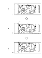
この図1に示すように構成されたシート折り装置50の動作についてZ折りを例にとり図2−1、図2−2を参照して用紙の流れを説明する。この例では、用紙折り部は3箇所あるため、第1撓み補助部材401、第2撓み補助部材402、第3撓み補助部材403を各折り部に備えている。以下に、Z折り、二つ折り、外三つ折り、内三つ折りの各折り動作について説明する。
The operation of the
<Z折り>
以下にZ折りの動作について説明する。画像形成装置より受け入れた用紙は、入口切替爪400によって第1ストッパ搬送路102へ案内される。第1ストッパ搬送路102内の第1ストッパ301に用紙先端を突き当てて撓ませ、第1折りローラ201と第2折りローラ202によって形成される第1ニップで1回目の折りを行う(図2−1(A),(B)参照)。
<Z-fold>
The Z-folding operation will be described below. The paper received from the image forming apparatus is guided to the first
1回目折りの撓み形成時には、第1撓み補助部材401を動作させ、用紙を折りローラ側に均一に撓ませる。1回目折り完了後、第1中継搬送路103から第2ストッパ搬送路104へ搬送され、第2ストッパ搬送路104内の第2ストッパ302に紙先端を突き当てて撓ませ、第3折りローラ203と第4折りローラ204によって形成される第2ニップで2回目の折りを行い(図2−1.2(C),(D)参照)、第2中継搬送路105にてZ折り完了となる。
When the first folding is formed, the first
2回目折りの撓み形成時にも、1回目同様に第2撓み補助部材402を動作させる。折り完了後、第3ストッパ搬送路106を通り、排紙搬送ローラ112によって下流機へ搬送される(図2−1(E),(F)参照)。Z折りモードでは、第3ストッパ303は使用しないため、第3ストッパ搬送路106から退避した位置にある。
When the second folding is formed, the second
<二つ折り>
以下に二つ折りの動作について説明する。画像形成装置60より受け入れた用紙は、入口切替爪400と第1撓み補助部材401によって、第1ストッパ搬送路102へは進入せずに、第1折りローラ201と第2折りローラ202によって形成される第1ニップを通過し、第1中継搬送路103を通って第2ストッパ搬送路104へ案内される。
<Folded>
Hereinafter, the folding operation will be described. The sheet received from the
第2ストッパ搬送路104内の第2ストッパ302に用紙先端を突き当てて撓ませ、第3折りローラ203と第4折りローラ204によって形成される第2ニップで2回目の折りを行い、第2中継搬送路105にて二つ折り完了となる。1回目折りの撓み形成時には、第2撓み補助部材402を動作させ、用紙を折りローラ側に均一に撓ませる。折り完了後、第3ストッパ搬送路106を通り、排紙搬送ローラ112によって下流機へ搬送される。二つ折りモードでは、第3ストッパ303は使用しないため、第3ストッパ搬送路106から退避した位置にある。
The front end of the sheet is abutted against the
<外三つ折り、内三つ折り>
以下に外三つ折り、内三つ折りの動作について説明する。画像形成装置60より受け入れた用紙は、入口切替爪400と第1撓み補助部材401によって、第1ストッパ搬送路102へは進入せずに、第1折りローラ201と第2折りローラ202によって形成される第1ニップを通過し、第1中継搬送路103を通って第2ストッパ搬送104へ案内される。
<Outer trifold, inner trifold>
The operation of the outer trifold and the inner trifold will be described below. The sheet received from the
第2ストッパ搬送路104内の第2ストッパ302に用紙先端を突き当てて撓ませ、第3折りローラ203と第4折りローラ204によって形成される第2ニップで1回目の折りを行い第2中継搬送路105にて1回目折り完了となる。1回目折り完了後、第3ストッパ搬送路106へ搬送され、第3ストッパ搬送路106内の第3ストッパ303に用紙先端を突き当てて撓ませ、第5折りローラ205と第6折りローラ206によって形成される第3ニップで2回目の折りを行い、スタッカー排紙搬送路107にて内三つ折り、外三つ折り完了となる。折り完了後、スタッカー排紙搬送ローラ113によってスタッカー部500へ収納される。
The front end of the sheet is abutted against the
図3は、図1における用紙折り部10aの基本構成およびこの用紙折り部10aを含む用紙後処理装置のシステム構成を示す説明図である。なお、この用紙折り部10aの基本構成は用紙折り部10bについても同一構成であるので、ここでは用紙折り部10aについて図示し、説明する。
FIG. 3 is an explanatory diagram showing the basic configuration of the
この図3において、符号10aは用紙折り部であり、後述するように、搬送ローラ対201,203、折りローラ対201,202、第1ストッパ搬送路102、用紙端検知センサ300、第1ストッパ301、第1撓み補助部材401、などを備えている。また、符号20は制御部、符号21はストッパ駆動部、符号22はドライバ、符号23はローラ駆動部、符号24はドライバ、符号50はシート折り装置、符号60は画像形成装置、符号61はシステムコントローラ、符号62はオペレーションパネルである。
In FIG. 3,
図3において、用紙折り機能を有するシート折り装置50と、複写機あるいはプリンタなどの画像形成装置60とは、画像形成装置60の排紙側とシート折り装置50の用紙搬入口とは用紙4の受け渡しが可能な搬送機構を有して機械的に接続され、かつ相互に制御信号などのやり取りが可能なように電気的にも接続されている。また、用紙折り部10aは、画像形成装置60から排紙される処理対象の用紙4を受け入れ、画像形成装置60のオペレーションパネル62を介してユーザの操作によって入力される用紙折りモードにしたがって所定の用紙折り処理を行う。
In FIG. 3, a
また、制御部20は、何れも不図示であるが、CPU,ROM,RAMなどを含むマイクロコンピュータシステムで構成され、画像形成装置60のシステムコントローラ61からの制御信号を受け、CPUがROMに格納されている制御プログラムにしたがい本装置各部を制御する。ストッパ駆動部21は、ステッピングモータを駆動源とし、各ストッパを用紙サイズや折り位置により位置を決めるよう動作させる。ドライバ22は、制御部20からの制御信号にしたがってストッパ駆動部21を駆動する。ローラ駆動部23は、DCブラシレスモータあるいはステッピングモータを駆動源とし、折りローラ対201、202、搬送ローラ対201、203を駆動する。ドライバ24は、制御部20からの制御信号にしたがってローラ駆動部23を駆動する。撓み補助部材駆動部25は、ソレノイドあるいはステッピングモータを駆動源とし、制御部20からの制御信号にしたがって撓み補助部材401を動作させる。
Although not shown, the
また、システムコントローラ61は、CPU,ROM,RAM(何れも不図示)などを含むマイクロコンピュータシステムで構成され、たとえば、電子写真プロセスによる画像形成、給紙搬送など画像形成に必要な各部を制御したり、外部装置、周辺機器(ここではシート折り装置50など)と制御信号を相互通信する。また、オペレーションパネル62は、ユーザによる各種入力を受け付けるキー、ボタン(ソフトキーを含む)など、および装置の状態、入力設定、モード設定状態などを表示するための液晶パネルなどを備えている。
The
つぎに、用紙折り部10aの構成、動作について説明する。図4は、図3における用紙折り部10aのレイアウト構成を示す説明図である。以下に用紙折り部10aによる用紙折りの基本動作について説明する。駆動側と従動側からなる折りローラ対201、202と、駆動側と隣接する搬送ローラ対201、203により用紙4が搬送される。第1ストッパ搬送路102には用紙先端が通過したことを検知する用紙端検知センサ300が第1ストッパ301に設けられている。用紙端検知センサ300は、たとえば、LED発光素子と受光素子とを一体に組み合わせた反射型の光センサを用いる。用紙は用紙端検知センサ300を通過した後、第1ストッパ搬送路102を遮断する第1ストッパ301に当接する。この当接後も搬送ローラ対201、203は、図の矢印方向に回転して用紙4を送ることにより、用紙4は折りローラ対201、202のニップ付近で撓み始める。
Next, the configuration and operation of the
続いて、制御部20は、用紙端検知センサ300による検知信号をトリガに規定のタイミングで用紙4を押すように搬送ローラ対201、203、折りローラ対201、202をドライバ24を介して制御して折りローラ対201、202のニップ側に用紙4を押し込む。この直後、制御部20は、撓み補助部材駆動部25を制御して第1撓み補助部材401を折りローラ対201、202のニップ側に移動させる動作を行う(図3の状態)。用紙4が折りローラ対201、202のニップに押し込まれた後、制御部20は、撓み補助部材駆動部25を制御して元の位置(図4の状態)に戻るよう第1撓み補助部材401を動作させる。
Subsequently, the
第1ストッパ301は、この実施の形態において、円弧状の第1ストッパ搬送路102に対し、円弧の中心付近に軸301aを持ち、軸301aを中心に可動する。制御部20は、第1ストッパ301の当接タイミングについて、用紙端検知センサ300と第1ストッパ301間の搬送距離と、線速(用紙搬送速度)から算出する。用紙端検知センサ300は、その検知部300aを第1ストッパ搬送路102側に向けた姿勢で第1ストッパ301に取り付けられており、検知部300aから第1ストッパ301の用紙当接面までの距離Lは常に一定に保たれている。
In this embodiment, the
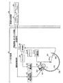
図5は、図2における用紙折り部30の構成を示す説明図である。なお、この用紙折り部30についても前述した図3に示した用紙折り部10aと同様の制御系が接続されている。この図5に示す用紙折り部30について以下に説明する。
FIG. 5 is an explanatory diagram showing a configuration of the
用紙折り部30は、湾曲状の搬送経路に折り対象の用紙を搬送する搬送手段と、搬送手段の下流側に配置され、搬送される用紙をニップ部分で折る第5折りローラ207、第6折りローラ209と、前記湾曲の円弧中心106Aとは異なる位置を回転中心303Aとして回転し、搬送される用紙の先端部分を当接させて用紙を停止する第3ストッパ303と、第3ストッパ303と一体で設けられ、搬送手段で搬送される用紙先端を検知する用紙端検知手段と、第3ストッパ303で停止され、搬送経路上で湾曲形状をなした用紙に対して接離可能に構成し、この湾曲形状をなした用紙の折り目となる近傍に接触して前記2つの折りローラ対のニップ部分に当該用紙を導く第3撓み補助部材403と、を備える。
The
前述するように第3ストッパ搬送路106は、Z折り、二つ折りモードでは第5折りローラ205と第6折りローラ206による折り動作は行わず、排紙搬送ローラ112によって下流機へ搬送しなければならないため、第3ストッパ搬送路106の円弧中心106Aとは異なる位置(本用紙折り部30の場合は上方向となる)に第3ストッパ303の回転中心303Aを配置し、第3ストッパ303を退避位置303aに移動することにより、第3ストッパ搬送路106を開放する。
As described above, the third
外三つ折り、内三つ折りモードでは、第5折りローラ205と第6折りローラ206による折りを行うため、折り位置に対応した303b〜303cに回転し、折り時のストッパの役割を果たす。
In the outer tri-fold and inner tri-fold modes, folding is performed by the
図5において、符号304は第3ストッパ303に設けられた検知板、符号305は検知板304を検知するホームポジションセンサである、このホームポジションセンサ305は複数個所に配置され、第3ストッパ303の待機位置を任意の位置に停止させることが可能になっている。たとえば、折り頻度の高い折りモードのZ折りの場合、第3ストッパ303のホームポジションを第3ストッパ303に設けられた検知板304をホームポジションセンサ305aで検出する退避位置303aにすることにより、第3ストッパ303に対する省電力化を行う。
In FIG. 5,
また、ユーザの使用形態に応じ、Z折り、二つ折りモードの使用頻度が高い場合は、ホームポジションセンサを符号305aに示す位置とし、他方、外三つ折り、内三つ折りモードの動作頻度が高い場合は、ホームポジションセンサを符号305bで示す位置となるように、たとえば画像形成装置60上のオペレーションパネル62等により選択することができるようにし、第3ストッパ303に対する省電力化を行う。
Also, when the usage frequency of the Z-folding and bi-folding modes is high according to the user's usage mode, the home position sensor is set to the position indicated by
したがって、以上説明してきたこの実施の形態にかかるシート折り装置によれば、図5に示すように、ストッパ部材(第3ストッパ303)の回転中心(回転中心303A)と湾曲した紙搬送経路(第3ストッパ搬送路106)の円弧の中心(円弧中心106A)を異なる位置に配置することにより、ストッパ部材(第3ストッパ303)の回転角を変更するのみにより、折り時のストッパ機能と折り動作を行わない場合の退避位置を両立することができ、湾曲搬送経路を折り時と折り動作を行わない場合で共有することが可能となるため、安価な構成において機械を大型化することなく、多様な折りモードに対応できる折り装置を提供するとこができる。
Therefore, according to the sheet folding apparatus according to this embodiment described above, as shown in FIG. 5, the rotation center (
また、ストッパ部材(第3ストッパ303)のホームポジションを使用頻度の高い折りモード時の位置に設定することにより、折り機に対する省電力化に貢献することができる。 Further, by setting the home position of the stopper member (third stopper 303) to the position in the folding mode with high use frequency, it is possible to contribute to power saving for the folding machine.
また、ストッパ部材(第3ストッパ303)のホームポジションをストッパ位置と退避位置とを選択可能とすることにより、さらにユーザの使用形態に対応した折り機に対する省電力化に貢献することができる。 In addition, by making the home position of the stopper member (the third stopper 303) selectable between the stopper position and the retracted position, it is possible to further contribute to power saving for the folding machine corresponding to the user's usage pattern.
以上のように、本発明にかかるシート折り装置および画像形成装置は、複写機やプリンタなどから排紙された用紙を所定の折りに仕上げるシート折り装置に有用であり、特に、折り時のストッパ機能と折りを行わない場合の退避位置を両立する装置に適している。 As described above, the sheet folding apparatus and the image forming apparatus according to the present invention are useful for a sheet folding apparatus that finishes a sheet discharged from a copying machine, a printer, or the like into a predetermined fold, and in particular, a stopper function at the time of folding. It is suitable for a device that achieves both a retracted position when folding is not performed.
10a,10b,30 用紙折り部
20 制御部
21 ストッパ駆動部
23 ローラ駆動部
25 撓み補助部材駆動部
50 シート折り装置
60 画像形成装置
61 システムコントローラ
62 オペレーションパネル
102 第1ストッパ搬送路
104 第2ストッパ搬送路
106 第3ストッパ搬送路
106A 円弧中心
207 第5折りローラ
209 第6折りローラ
300 用紙端検知センサ
301 第1ストッパ
302 第2ストッパ
303 第3ストッパ
303A 回転中心
305a,305b ホームポジションセンサ
401,402,403 撓み補助部材
10a, 10b, 30
Claims (4)
前記搬送手段の下流側に配置され、前記搬送手段により搬送される用紙をニップ部分で折る折りローラ対と、
前記湾曲をなす搬送経路の湾曲中心軸とは異なる位置を中心軸として回転し、前記搬送手段で搬送される用紙の先端部分を当接させて用紙を停止するストッパ部材と、
前記ストッパ部材と一体で設けられ、前記搬送手段で搬送される用紙先端を検知する用紙先端検知手段と、
前記ストッパ部材で停止され、前記搬送経路上で湾曲形状をなした用紙に対して接離可能に構成し、この湾曲形状をなした用紙の折り目となる近傍に接触して前記折りローラ対のニップ部分に当該用紙を導く用紙導入手段と、
を備えることを特徴とするシート折り装置。 Conveying means for conveying a sheet to be folded to a curved conveying path;
A pair of folding rollers which are arranged on the downstream side of the conveying means and fold the paper conveyed by the conveying means at a nip portion;
A stopper member that rotates about a position different from the curved central axis of the curved conveyance path and stops the paper by contacting the leading end portion of the paper conveyed by the conveying means;
A paper leading edge detecting means which is provided integrally with the stopper member and detects the leading edge of the paper conveyed by the conveying means;
It is configured to be stopped by the stopper member so as to be able to come into contact with and separate from the paper having a curved shape on the conveyance path. A paper introduction means for guiding the paper to a part;
A sheet folding apparatus comprising:
前記待機位置検知手段は、使用頻度の高い折りモード時に対応した待機位置に設定されることを特徴とする請求項1に記載のシート折り装置。 Furthermore, a standby position detecting means for detecting a stop position of the stopper member during standby is provided,
The sheet folding apparatus according to claim 1, wherein the standby position detection unit is set to a standby position corresponding to a frequently used folding mode.
前記待機位置検知手段による前記ストッパ部材の停止位置を選択する選択手段を備えることを特徴とする請求項2に記載のシート折り装置。 Further, the standby position detecting means is arranged at a plurality of locations,
The sheet folding apparatus according to claim 2, further comprising a selection unit that selects a stop position of the stopper member by the standby position detection unit.
Priority Applications (1)
| Application Number | Priority Date | Filing Date | Title |
|---|---|---|---|
| JP2011005924A JP5585460B2 (en) | 2011-01-14 | 2011-01-14 | Sheet folding apparatus and image forming apparatus |
Applications Claiming Priority (1)
| Application Number | Priority Date | Filing Date | Title |
|---|---|---|---|
| JP2011005924A JP5585460B2 (en) | 2011-01-14 | 2011-01-14 | Sheet folding apparatus and image forming apparatus |
Publications (2)
| Publication Number | Publication Date |
|---|---|
| JP2012144361A true JP2012144361A (en) | 2012-08-02 |
| JP5585460B2 JP5585460B2 (en) | 2014-09-10 |
Family
ID=46788357
Family Applications (1)
| Application Number | Title | Priority Date | Filing Date |
|---|---|---|---|
| JP2011005924A Expired - Fee Related JP5585460B2 (en) | 2011-01-14 | 2011-01-14 | Sheet folding apparatus and image forming apparatus |
Country Status (1)
| Country | Link |
|---|---|
| JP (1) | JP5585460B2 (en) |
Cited By (2)
| Publication number | Priority date | Publication date | Assignee | Title |
|---|---|---|---|---|
| JP2012224427A (en) * | 2011-04-19 | 2012-11-15 | Ricoh Co Ltd | Sheet folding device, and image forming apparatus |
| CN104191833A (en) * | 2014-08-25 | 2014-12-10 | 浪潮软件集团有限公司 | Paper feeder for printer |
Citations (3)
| Publication number | Priority date | Publication date | Assignee | Title |
|---|---|---|---|---|
| JPH10167562A (en) * | 1996-12-13 | 1998-06-23 | Canon Aptecs Kk | Sheet processing apparatus and image forming apparatus |
| JP2006076776A (en) * | 2004-09-13 | 2006-03-23 | Nisca Corp | Sheet handling device and image forming device using it |
| JP2009067537A (en) * | 2007-09-13 | 2009-04-02 | Ricoh Co Ltd | Paper folding device, paper processing system, and image forming system |
-
2011
- 2011-01-14 JP JP2011005924A patent/JP5585460B2/en not_active Expired - Fee Related
Patent Citations (3)
| Publication number | Priority date | Publication date | Assignee | Title |
|---|---|---|---|---|
| JPH10167562A (en) * | 1996-12-13 | 1998-06-23 | Canon Aptecs Kk | Sheet processing apparatus and image forming apparatus |
| JP2006076776A (en) * | 2004-09-13 | 2006-03-23 | Nisca Corp | Sheet handling device and image forming device using it |
| JP2009067537A (en) * | 2007-09-13 | 2009-04-02 | Ricoh Co Ltd | Paper folding device, paper processing system, and image forming system |
Cited By (2)
| Publication number | Priority date | Publication date | Assignee | Title |
|---|---|---|---|---|
| JP2012224427A (en) * | 2011-04-19 | 2012-11-15 | Ricoh Co Ltd | Sheet folding device, and image forming apparatus |
| CN104191833A (en) * | 2014-08-25 | 2014-12-10 | 浪潮软件集团有限公司 | Paper feeder for printer |
Also Published As
| Publication number | Publication date |
|---|---|
| JP5585460B2 (en) | 2014-09-10 |
Similar Documents
| Publication | Publication Date | Title |
|---|---|---|
| JP5605119B2 (en) | Paper folding apparatus and image forming apparatus | |
| JP2004277037A (en) | Sheet binding method and sheet post-processing device | |
| CN111285172B (en) | Sheet folding device and pattern forming device | |
| JP2012056674A (en) | Post-processing apparatus | |
| JP4157433B2 (en) | Paper folding device | |
| JP5262637B2 (en) | Curl correction device, image forming device, and sheet paper post-processing device | |
| JP5585460B2 (en) | Sheet folding apparatus and image forming apparatus | |
| US9108820B2 (en) | Sheet folding apparatus and image forming apparatus | |
| JP2011093689A (en) | Sheet folding device and image forming system with the same | |
| JP2012214295A (en) | Sheet processing apparatus that flattens folded spine of sheet bundle, and image forming apparatus including the sheet processing apparatus | |
| US11987469B2 (en) | Sheet folding device, sheet post-processor provided with the same, and image forming system | |
| JP5760479B2 (en) | Paper folding mechanism, paper folding device using the same, and image forming apparatus | |
| JP5560993B2 (en) | Sheet folding apparatus and image forming apparatus | |
| JP4460614B2 (en) | Sheet folding device | |
| JP5446831B2 (en) | Paper folding device | |
| JP5765613B2 (en) | Paper folding apparatus and image forming apparatus | |
| JP4159412B2 (en) | Sheet folding device | |
| JP5217894B2 (en) | Sheet folding apparatus and image forming system | |
| JP5778973B2 (en) | Sheet folding apparatus and image forming system provided with the same | |
| JP5750939B2 (en) | Sheet stacking apparatus, sheet folding apparatus, and image forming system | |
| JP2012126475A (en) | Paper post-processing device | |
| JP2011093688A (en) | Sheet folding device and image forming system with the same | |
| JP2011184146A (en) | Paper folding device | |
| JP2011093684A (en) | Sheet folding device and image forming system having the same | |
| JP2011093685A (en) | Sheet folding device and image forming system having the same |
Legal Events
| Date | Code | Title | Description |
|---|---|---|---|
| A625 | Written request for application examination (by other person) |
Free format text: JAPANESE INTERMEDIATE CODE: A625 Effective date: 20130404 |
|
| A711 | Notification of change in applicant |
Free format text: JAPANESE INTERMEDIATE CODE: A711 Effective date: 20130423 |
|
| RD02 | Notification of acceptance of power of attorney |
Free format text: JAPANESE INTERMEDIATE CODE: A7422 Effective date: 20130621 |
|
| A977 | Report on retrieval |
Free format text: JAPANESE INTERMEDIATE CODE: A971007 Effective date: 20140206 |
|
| A131 | Notification of reasons for refusal |
Free format text: JAPANESE INTERMEDIATE CODE: A131 Effective date: 20140212 |
|
| A521 | Written amendment |
Free format text: JAPANESE INTERMEDIATE CODE: A523 Effective date: 20140411 |
|
| TRDD | Decision of grant or rejection written | ||
| A01 | Written decision to grant a patent or to grant a registration (utility model) |
Free format text: JAPANESE INTERMEDIATE CODE: A01 Effective date: 20140624 |
|
| A61 | First payment of annual fees (during grant procedure) |
Free format text: JAPANESE INTERMEDIATE CODE: A61 Effective date: 20140707 |
|
| R151 | Written notification of patent or utility model registration |
Ref document number: 5585460 Country of ref document: JP Free format text: JAPANESE INTERMEDIATE CODE: R151 |
|
| LAPS | Cancellation because of no payment of annual fees |