JP2012144337A - Passenger conveyor - Google Patents

Passenger conveyor Download PDF

Info

Publication number
JP2012144337A
JP2012144337A JP2011004203A JP2011004203A JP2012144337A JP 2012144337 A JP2012144337 A JP 2012144337A JP 2011004203 A JP2011004203 A JP 2011004203A JP 2011004203 A JP2011004203 A JP 2011004203A JP 2012144337 A JP2012144337 A JP 2012144337A
Authority
JP
Japan
Prior art keywords
opening
closing
passenger conveyor
boarding
closing part
Prior art date
Legal status (The legal status is an assumption and is not a legal conclusion. Google has not performed a legal analysis and makes no representation as to the accuracy of the status listed.)
Pending
Application number
JP2011004203A
Other languages
Japanese (ja)
Inventor
Kiyoshi Uchida
潔 内田
Current Assignee (The listed assignees may be inaccurate. Google has not performed a legal analysis and makes no representation or warranty as to the accuracy of the list.)
Toshiba Elevator and Building Systems Corp
Original Assignee
Toshiba Elevator Co Ltd
Priority date (The priority date is an assumption and is not a legal conclusion. Google has not performed a legal analysis and makes no representation as to the accuracy of the date listed.)
Filing date
Publication date
Application filed by Toshiba Elevator Co Ltd filed Critical Toshiba Elevator Co Ltd
Priority to JP2011004203A priority Critical patent/JP2012144337A/en
Publication of JP2012144337A publication Critical patent/JP2012144337A/en
Pending legal-status Critical Current

Links

Images

Landscapes

  • Escalators And Moving Walkways (AREA)

Abstract

PROBLEM TO BE SOLVED: To provide a passenger conveyor equipped with footboard plates of subdivided double door system which slide vertically in the standing state at the time of opening.SOLUTION: In the passenger conveyor in an escalator where an openable and closable footboard plate is prepared as a door to a machinery room at a platform, the footboard plate consists of a right opening and closing body 16 and a left opening and closing body 11 arranged in right and left side against the boarding and alighting direction of the passenger conveyor, respectively, the right opening and closing body 16 consists of right opening and closing sections 17, 18 and 19 subdivided plurally into the longitudinal direction against the boarding and alighting direction of the passenger conveyor, the left opening and closing body 11 consists of left opening and closing sections 12, 13 and 14 subdivided plurally into the longitudinal direction against the boarding and alighting direction of the passenger conveyor, the right opening and closing sections are openable to the standing direction at the right end side of footboard plate individually, and the left opening and closing sections are openable to the standing direction at the left end side of footboard plate individually.

Description

本発明の実施形態は、乗客コンベアに関する。   Embodiments of the present invention relate to a passenger conveyor.

従来より、エスカレータや動く歩道等の乗客コンベアにおいて、乗客コンベアの乗降口に配されている機械室への開閉扉となる乗降板の着脱を簡便にすることにより、保守点検の時間が制限されている重要物件の作業時間の短縮を図る提案がなされている。   Conventionally, in passenger conveyors such as escalators and moving walkways, maintenance and inspection time has been limited by simplifying the attachment and detachment of the boarding doors to the machine room located at the entrance of the passenger conveyor. Proposals have been made to reduce the working hours of important properties.

従来より行われていた乗降板着脱の一方法としては、顧客区分の共用部分へ養生シートを敷き、該養生シート上に重量物である乗降板を積み重ねていた。狭い通路に設置された乗客コンベアにおいては、共用部の広いスペースまで乗降板を移動することにより利用者の安全確保に努めていた。   As a conventional method for attaching and detaching a boarding / alighting board, a curing sheet is laid on a shared part of a customer division, and a boarding board that is a heavy object is stacked on the curing sheet. In passenger conveyors installed in narrow passages, efforts were made to ensure the safety of users by moving boarding boards to wide spaces in common areas.

緊急な故障においても、重量物である乗降板を移動し、さらに第三者への安全配慮のために安全柵を設置してメンテナンス作業の実施をしていた。物件によっては、百貨店等のように景観上の都合により安全柵の収納倉庫が遠いところもあり、安全柵の設置に時間を要し、手間がかかっていた。   Even in the event of an urgent failure, a heavy boarding board was moved and maintenance work was carried out by installing a safety fence to ensure safety for third parties. Some properties, such as department stores, have remote storage facilities for safety fences due to landscape reasons, and it took time and effort to install safety fences.

実開昭62−47589号公報Japanese Utility Model Publication No. 62-47589 特開平8−73162号公報JP-A-8-73162

上記のような従来の乗降板着脱方法においては、保守点検作業において重量物である乗降板を持ち上げる際に腰に負担が掛かり、また特殊な広幅の乗降板に対しては2人作業での移動を余儀なくされていた。   In the conventional boarding / alighting plate attachment / detachment method as described above, a burden is placed on the waist when lifting the boarding / alighting board, which is a heavy object in maintenance / inspection work, and for a special wide boarding / alighting board, movement by two persons is performed. Had to be forced.

そこで、本発明の実施形態は、用品を設計や製造を行う側の目線ではなく、保守作業を行う現場サイド側の目線に着目して検討を行い、細分化された観音開き方式で、開口時の起立状態において上下にスライドする乗降板を備えた乗客コンベアを提供することを目的とする。   Therefore, in the embodiment of the present invention, examination is performed by paying attention to the viewpoint on the site side where the maintenance work is performed, not the viewpoint on the side where the product is designed or manufactured, and the subdivided double door system is used at the time of opening. It aims at providing the passenger conveyor provided with the boarding board which slides up and down in a standing state.

本発明の実施形態に係る乗客コンベアは、機械室への扉として開閉可能な乗降板を乗降口に備えた乗客コンベアにおいて、前記乗降板は、乗客コンベアの乗降方向に対してその左右に配される左側開閉体と右側開閉体とから構成され、前記左側開閉体は、乗客コンベアの乗降方向に対してその前後方向に複数に分割された左側開閉部からなり、前記右側開閉体は、乗客コンベアの乗降方向に対してその前後方向に複数に分割された右側開閉部からなり、前記左側開閉部は、個々に乗降板左端側に起立する方向に開口可能であり、前記右側開閉部は、個々に乗降板右端側に起立する方向に開口可能であることを特徴とする。   A passenger conveyor according to an embodiment of the present invention is a passenger conveyor provided with a boarding / exiting board that can be opened and closed as a door to a machine room. The boarding board is disposed on the left and right sides of the boarding / alighting direction of the passenger conveyor. The left-side opening / closing body comprises a left-side opening / closing portion divided into a plurality of front-rear directions with respect to a passenger conveyor getting-on / off direction, and the right-side opening / closing body is a passenger conveyor. The left opening / closing part can be opened in the direction of standing on the left end side of the boarding / alighting plate, and the right opening / closing part can be individually opened. It is possible to open in the direction of standing on the right end side of the board.

本発明の実施態様に係る乗客コンベアにおいて、乗降板が閉塞されている状態を表す概略斜視図である。In the passenger conveyor which concerns on the embodiment of this invention, it is a schematic perspective view showing the state by which the boarding board is obstruct | occluded. 本発明の実施態様に係る乗客コンベアにおいて、乗降板が開口されている状態を表す概略斜視図である。In the passenger conveyor which concerns on the embodiment of this invention, it is a schematic perspective view showing the state by which the boarding board is opened. 本発明の実施態様に係る乗客コンベアに備える乗降板の閉塞した状態を表す斜視図である。It is a perspective view showing the state which the boarding board provided in the passenger conveyor concerning the embodiment of the present invention obstruct | occluded. 本発明の実施態様に係る乗客コンベアに備える乗降板の開口した状態を表す斜視図である。It is a perspective view showing the state where the boarding board provided in the passenger conveyor concerning the embodiment of the present invention opened. 本発明の実施態様に係る乗客コンベアに備える乗降板の左側開閉部の斜視図であって、(a)は表面側から見た斜視図であり、(b)は裏面側から見た斜視図である。BRIEF DESCRIPTION OF THE DRAWINGS It is a perspective view of the left opening / closing part of the boarding board provided in the passenger conveyor which concerns on the embodiment of this invention, Comprising: (a) is the perspective view seen from the surface side, (b) is the perspective view seen from the back side. is there. 本発明の実施態様に係る乗客コンベアに備える乗降板の右側開閉部の斜視図であって、(a)は表面側から見た斜視図であり、(b)は裏面側から見た斜視図である。BRIEF DESCRIPTION OF THE DRAWINGS It is a perspective view of the right opening / closing part of the boarding board provided in the passenger conveyor which concerns on the embodiment of this invention, Comprising: (a) is the perspective view seen from the surface side, (b) is the perspective view seen from the back side. is there. 乗降板閉塞時における締結装置であって、(a)はネジ軸の概略斜視図であり、(b)は締め付け具の概略斜視図である。It is a fastening device at the time of boarding board obstruction | occlusion, Comprising: (a) is a schematic perspective view of a screw shaft, (b) is a schematic perspective view of a fastening tool. 左側開閉部と右側開閉部との突き合わせ部分における隙間について、(a)は弾性体を介在させていない状態を示す概略斜視図であり、(b)は弾性体を介在させた状態を示す概略斜視図である。(A) is a schematic perspective view showing a state in which an elastic body is not interposed, and (b) is a schematic perspective view showing a state in which an elastic body is interposed. FIG.

以下、本発明の実施例に係る乗客コンベアについて、図面を参照して説明する。   Hereinafter, a passenger conveyor according to an embodiment of the present invention will be described with reference to the drawings.

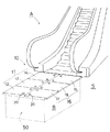
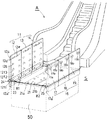
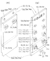
図1及び図2においてAはエスカレータを示し、エスカレータAの下階側乗降口の下方に機械室が設けられている。そして、該機械室には、これを取り囲んで蓋をするように天板となる乗降板10と周壁部のフレーム50とからなるマンホール体Bが埋め込まれている。   1 and 2, A indicates an escalator, and a machine room is provided below the lower floor entrance of the escalator A. In the machine room, a manhole body B including a boarding board 10 serving as a top plate and a frame 50 of the peripheral wall is embedded so as to surround and cover the machine room.

前記乗降板10は機械室への扉として使用するため、開閉可能となっている。すなわち、エスカレータAの乗降方向に対して、その左側には左側開閉体11が配されており、その右側には右側開閉体16が配されており、左側開閉体11と右側開閉体16とで開閉可能な乗降板10が構成されている。   Since the boarding board 10 is used as a door to the machine room, it can be opened and closed. That is, the left opening / closing body 11 is disposed on the left side of the escalator A and the right opening / closing body 16 is disposed on the right side thereof. An entrance / exit plate 10 that can be opened and closed is configured.

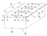
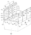
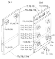
そして、図3及び図4に示すように、左側開閉体11は、エスカレータAの乗降方向に対して、その前後方向に3分割された左側開閉部12、13、14から構成されており、各左側開閉部12、13、14は、個々に乗降板左端側に起立する方向に開口可能に構成されている。また右側開閉体16は、エスカレータAの乗降方向に対して、その前後方向に3分割された右側開閉部17、18、19から構成されており、各右側開閉部17、18、19は、個々に乗降板右端側に起立する方向に開口可能に構成されている。なお、本実施例においては、乗降板を左右に二分し、前後に3分割したものであるが、特にこれに限られるものではなく、乗降板全体の大きさ及び重量により適宜変更可能であり、一人の人力で簡単に開閉できるように構成する。   And as shown in FIG.3 and FIG.4, the left side opening-and-closing body 11 is comprised from the left-side opening-and-closing part 12,13,14 divided into 3 in the front-back direction with respect to the getting-on / off direction of the escalator A, The left opening / closing parts 12, 13, and 14 are configured to be openable in the direction of standing on the left end side of the boarding / alighting plate individually. The right opening / closing body 16 is composed of right opening / closing parts 17, 18, 19 divided in the front-rear direction with respect to the direction of getting on / off of the escalator A. The right opening / closing parts 17, 18, 19 are individually provided. It is configured to be able to open in a direction to stand on the right end side of the boarding / exiting plate. In this embodiment, the boarding board is divided into left and right, and divided into three parts before and after, but is not limited to this, and can be appropriately changed depending on the size and weight of the boarding board, It is configured so that it can be easily opened and closed by one person.

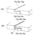
そして、各左側開閉部12、13、14は、図5及び図6に示すように、その右側開閉部との突き合わせ部分には下側に肉薄となる段差部12a、13a、14aが形成され、各右側開閉部17、18、19は、その左側開閉部との突き合わせ部分に上側に肉薄となる段差部17a、18a、19aが形成されており、乗降板10の閉塞する際に、各左側開閉部12、13、14を傾倒した後、各右側開閉部17、18、19を傾倒することにより、各左側開閉部の段差部12a、13a、14aの上に各右側開閉部の段差部17a、18a、19aが重なり合ってフラットな閉塞面を形成する状態となる。   As shown in FIGS. 5 and 6, each left opening / closing part 12, 13, 14 is formed with stepped parts 12 a, 13 a, 14 a that are thin on the lower side at the abutting part with the right opening / closing part, Each of the right opening / closing parts 17, 18 and 19 is formed with stepped parts 17a, 18a and 19a which are thin on the upper side at the abutting portion with the left opening and closing part. After tilting the parts 12, 13, and 14, the right opening and closing parts 17, 18, and 19 are tilted, so that the step parts 17a of the right opening and closing parts are placed on the step parts 12a, 13a, and 14a of the left opening and closing parts. 18a and 19a overlap to form a flat closed surface.

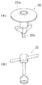
また、各左側開閉部12、13、14には、その上部2箇所に、中心に通孔12b、13b、14bを有する円形凹部12c、13c、14cが形成されている。この通孔12b、13b、14bにネジ軸20を挿入してマンホール体Bの中央上部に架け渡されている支持梁21に締結することにより各左側開閉部12、13、14が閉塞固定される。すなわち、各左側開閉部12、13、14の通孔12b、13b、14bにネジ軸20を挿入し、円形凹部12c、13c、14cにネジ軸20の頭部20aを嵌め、ネジ軸20の先端雄ネジ部20bをマンホール体Bの中央上部に架け渡されている支持梁21の雌ネジ穴21aに、締め付け具22を使用して螺合することにより、各左側開閉部12、13、14は閉塞状態において固定されることになる。なお、各左側開閉部12、13、14の上部に配した通孔12d、13d、14dは、次記する右側開閉部17、18、19を閉塞固定する際に使用するものである。   In addition, circular recesses 12c, 13c, and 14c having through holes 12b, 13b, and 14b at the centers are formed in the left and right opening / closing parts 12, 13, and 14, respectively, at two upper portions thereof. By inserting the screw shaft 20 into the through holes 12b, 13b, and 14b and fastening the screw shaft 20 to the support beam 21 spanning the upper center of the manhole body B, the left opening and closing parts 12, 13, and 14 are closed and fixed. . That is, the screw shaft 20 is inserted into the through holes 12b, 13b, 14b of the left opening / closing portions 12, 13, 14, and the head 20a of the screw shaft 20 is fitted into the circular recesses 12c, 13c, 14c. By screwing the male screw portion 20b into the female screw hole 21a of the support beam 21 spanning the center upper portion of the manhole body B using the fastening tool 22, each of the left opening and closing portions 12, 13, and 14 is It will be fixed in the closed state. The through holes 12d, 13d, and 14d disposed above the left opening / closing parts 12, 13, and 14 are used for closing and fixing the right opening / closing parts 17, 18, and 19 described below.

各右側開閉部17、18、19にも、その上部2箇所に、中心に通孔17b、18b、19bを有する円形凹部17c、18c、19cが形成されている。この通孔17b、18b、19bにネジ軸20を挿入すると共に、左側開閉部12、13、14について前述した左側開閉部の通孔12d、13d、14dに挿入し、円形凹部17c、18c、19cにネジ軸20の頭部20aを嵌め、ネジ軸20の先端雄ネジ部20bをマンホール体Bの中央上部に架け渡されている支持梁21の雌ネジ穴21bに、締め付け具22を使用して螺合することにより、各左側開閉部17、18、19は閉塞状態において固定されることになる。ネジ軸20及び締め付け具22の詳細を図7に示す。   Each of the right opening / closing parts 17, 18 and 19 is also formed with circular recesses 17c, 18c and 19c having through holes 17b, 18b and 19b in the center at two locations on the upper side. The screw shaft 20 is inserted into the through holes 17b, 18b, and 19b, and the left opening and closing parts 12, 13, and 14 are inserted into the through holes 12d, 13d, and 14d of the left opening and closing parts described above, and the circular recesses 17c, 18c, and 19c are inserted. The head 20a of the screw shaft 20 is fitted to the screw shaft 20, and the end male screw portion 20b of the screw shaft 20 is inserted into the female screw hole 21b of the support beam 21 spanned over the central upper portion of the manhole body B by using a fastening tool 22. By screwing, the left opening / closing parts 17, 18, and 19 are fixed in the closed state. Details of the screw shaft 20 and the fastening tool 22 are shown in FIG.

各左側開閉部12、13、14及び各右側開閉部17、18、19を開口する際には、各左側開閉部及び各右側開閉部に螺合されているネジ軸20を締め付け具22を使用して取り外す。   When opening each left opening / closing part 12, 13, 14 and each right opening / closing part 17, 18, 19, open the screw shaft 20 screwed to each left opening / closing part and each right opening / closing part. And remove.

そして、まず各右側開閉部17、18、19を個別に起立させる。すなわち、各右側開閉部の段差部17a、18a、19aを一つずつ上げて、裏面の上部に配した取っ手17e、18e、19eを利用して各右側開閉部を個別に持ち上げ、各右側開閉部の下端をマンホール体Bの上縁B1と建屋の床面との隙間に若干降下させる。このマンホール体Bの上縁B1と建屋の床面Sとの隙間を形成するために各右側開閉部の閉塞状態において各右側開閉部の下端が各右側開閉部の厚み分だけマンホール体Bからはみ出すように設計する。次に、各右側開閉部17、18、19の裏面に形成した逆T字型凹部17f1、18f1、19f1の横孔17g1、18g1、19g1にT字型支持軸23の挿入軸部23aを挿入する。挿入した挿入軸部23aを逆T字型凹部の縦孔17h1、18h1、19h1に沿って上方にスライドさせ、T字型支持軸23の突出軸部23bをマンホール体Bの上縁B1に位置させて、各右側開閉部17、18、19をT字型支持軸23の突出軸部23bで支持させる。これにより、各右側開閉部17、18、19の起立状態が維持されることになる。なお、上記の作業をやりやすくするために、各右側開閉部の下端の底面側に段差部17a’、18a’、19a’を形成してマンホール体Bの上縁B1に一時的に載置できるようにしておく。   First, the right opening / closing parts 17, 18 and 19 are individually erected. That is, the stepped portions 17a, 18a, 19a of each right opening / closing portion are raised one by one, and each right opening / closing portion is lifted individually using the handles 17e, 18e, 19e arranged on the upper surface of the back surface. Is slightly lowered into the gap between the upper edge B1 of the manhole body B and the floor of the building. In order to form a gap between the upper edge B1 of the manhole body B and the floor S of the building, the lower end of each right opening / closing part protrudes from the manhole body B by the thickness of each right opening / closing part in the closed state of each right opening / closing part. To design. Next, the insertion shaft portion 23a of the T-shaped support shaft 23 is inserted into the lateral holes 17g1, 18g1, 19g1 of the inverted T-shaped concave portions 17f1, 18f1, 19f1 formed on the back surfaces of the right opening / closing portions 17, 18, 19, respectively. . The inserted insertion shaft portion 23a is slid upward along the vertical holes 17h1, 18h1, 19h1 of the inverted T-shaped recess, and the protruding shaft portion 23b of the T-shaped support shaft 23 is positioned at the upper edge B1 of the manhole body B. The right opening / closing parts 17, 18, 19 are supported by the protruding shaft part 23 b of the T-shaped support shaft 23. Thereby, the standing state of each right side opening-and-closing part 17, 18, and 19 is maintained. In order to facilitate the above work, stepped portions 17a ′, 18a ′, 19a ′ can be formed on the bottom surface side of the lower end of each right side opening / closing portion to be temporarily placed on the upper edge B1 of the manhole body B. Keep it like that.

また、起立状態にある各右側開閉部17、18、19の高さを低くするためには、T字型支持軸23を逆T字型凹部17f1、18f1、19f1から引き抜き、逆T字型凹部17f1、18f1、19f1の上方にある逆T字型凹部17f2、18f2、19f2の横孔17g2、18g2、19g2に、前記と同様にT字型支持軸23の挿入軸部23aを挿入する。挿入した挿入軸部23aを逆T字型凹部の縦孔17h2、18h2、19h2に沿って上方にスライドさせ、突出軸部23bをマンホール体Bの上縁B1に位置させて、各右側開閉部17、18、19をT字型支持軸23の突出軸部23bで支持させる。これにより、各右側開閉部17、18、19が低い位置で、その起立状態が維持されることになる。さらに、起立状態にある各右側開閉部17、18、19の高さを低くするためには、T字型支持軸23を逆T字型凹部17f2、18f2、19f2から引き抜き、逆T字型凹部17f2、18f2、19f2の上方にある逆T字型凹部17f3、18f3、19f3の横孔17g3、18g3、19g3に、前記と同様にT字型支持軸23の挿入軸部23aを挿入する。挿入した挿入軸部23aを逆T字型凹部の縦孔17h3、18h3、19h3に沿って上方にスライドさせ、突出軸部23bをマンホール体Bの上縁B1に位置させて、各右側開閉部17、18、19をT字型支持軸23の突出軸部23bで支持させる。これにより、各右側開閉部17、18、19がより一層低い位置で、その起立状態が維持されることになる。なお、各右側開閉部17、18、19を最も高い位置における起立状態で維持させる場合には、安全性を高めるために、各右側開閉部17、18、19の下部に形成した貫通孔17i、18i、19iに貫通軸24を通す。貫通孔17i、18i、19iを形成する位置は、貫通軸24を通したときに、貫通軸24の端部が建屋の床面Sに接触するように設計する。   In order to reduce the height of each of the right opening / closing parts 17, 18, and 19 in the standing state, the T-shaped support shaft 23 is pulled out from the inverted T-shaped recesses 17f1, 18f1, 19f1, and the inverted T-shaped recesses The insertion shaft portion 23a of the T-shaped support shaft 23 is inserted into the lateral holes 17g2, 18g2, 19g2 of the inverted T-shaped recesses 17f2, 18f2, 19f2 above 17f1, 18f1, 19f1 in the same manner as described above. The inserted insertion shaft portion 23a is slid upward along the vertical holes 17h2, 18h2, 19h2 of the inverted T-shaped recesses, and the protruding shaft portion 23b is positioned at the upper edge B1 of the manhole body B so that each right opening / closing portion 17 , 18 and 19 are supported by the protruding shaft portion 23 b of the T-shaped support shaft 23. Thereby, the standing state is maintained in the position where each right opening and closing part 17, 18, 19 is low. Further, in order to reduce the height of each of the right opening / closing parts 17, 18, 19 in the standing state, the T-shaped support shaft 23 is pulled out from the inverted T-shaped recesses 17f2, 18f2, 19f2, and the inverted T-shaped recesses The insertion shaft portion 23a of the T-shaped support shaft 23 is inserted into the lateral holes 17g3, 18g3, and 19g3 of the inverted T-shaped concave portions 17f3, 18f3, and 19f3 above the 17f2, 18f2, and 19f2, respectively. The inserted insertion shaft portion 23a is slid upward along the vertical holes 17h3, 18h3, 19h3 of the inverted T-shaped recesses, and the protruding shaft portion 23b is positioned at the upper edge B1 of the manhole body B so that each right opening / closing portion 17 , 18 and 19 are supported by the protruding shaft portion 23 b of the T-shaped support shaft 23. Thereby, the standing state is maintained at the position where each of the right opening / closing parts 17, 18, 19 is further lowered. In addition, when maintaining each right side opening-and-closing part 17,18,19 in the standing state in the highest position, in order to improve safety, through-hole 17i formed in the lower part of each right-side opening / closing part 17,18,19, The penetrating shaft 24 is passed through 18i and 19i. The positions where the through holes 17i, 18i, and 19i are formed are designed so that the end of the through shaft 24 contacts the floor surface S of the building when the through shaft 24 is passed.

次に各左側開閉部12、13、14を個別に起立させる。すなわち、各左側開閉部の段差部12a、13a、14aを一つずつ上げて、裏面の上部に配した取っ手12e、13e、14eを利用して各左側開閉部を個別に持ち上げ、各左側開閉部の下端をマンホール体Bの上縁B2と建屋の床面との隙間に降下させる。このマンホール体Bの上縁B2と建屋の床面Sとの隙間を形成するために各左側開閉部の閉塞状態において各左側開閉部の下端が各左側開閉部の厚み分だけマンホール体Bからはみ出すように設計する。そして、各左側開閉部12、13、14の裏面に形成した逆T字型凹部12f1、13f1、14f1の横孔12g1、13g1、14g1にT字型支持軸23の挿入軸部23aを挿入する。挿入した挿入軸部23aを逆T字型凹部の縦孔12h1、13h1、14h1に沿って上方にスライドさせ、T字型支持軸23の突出軸部23bをマンホール体Bの上縁B2に位置させて、各左側開閉部12、13、14をT字型支持軸23の突出軸部23bで支持させる。これにより、各左側開閉部12、13、14の起立状態が維持されることになる。なお、上記の作業をやりやすくするために、各右側開閉部の下端の底面側に段差部12a’、13a’、14a’を形成してマンホール体Bの上縁B2に一時的に載置できるようにしておく。   Next, the left opening / closing parts 12, 13, and 14 are individually erected. That is, the stepped portions 12a, 13a, and 14a of each left-side opening and closing portion are raised one by one, and the left-side opening and closing portions are individually lifted using the handles 12e, 13e, and 14e arranged on the upper surface of the back surface. Is lowered to the gap between the upper edge B2 of the manhole body B and the floor of the building. In order to form a gap between the upper edge B2 of the manhole body B and the floor surface S of the building, the lower end of each left opening / closing part protrudes from the manhole body B by the thickness of each left opening / closing part in the closed state of each left opening / closing part. To design. Then, the insertion shaft portion 23a of the T-shaped support shaft 23 is inserted into the lateral holes 12g1, 13g1, and 14g1 of the inverted T-shaped concave portions 12f1, 13f1, and 14f1 formed on the back surfaces of the left opening and closing portions 12, 13, and 14, respectively. The inserted insertion shaft 23a is slid upward along the vertical holes 12h1, 13h1, 14h1 of the inverted T-shaped recess, and the protruding shaft 23b of the T-shaped support shaft 23 is positioned at the upper edge B2 of the manhole body B. Thus, the left open / close portions 12, 13, 14 are supported by the protruding shaft portion 23 b of the T-shaped support shaft 23. Thereby, the standing state of each left-hand side opening-and-closing part 12, 13, and 14 is maintained. In order to facilitate the above work, stepped portions 12a ′, 13a ′, and 14a ′ can be formed on the bottom surface side of the lower end of each right side opening / closing portion to be temporarily placed on the upper edge B2 of the manhole body B. Keep it like that.

また、起立状態にある各左側開閉部12、13、14の高さを低くするためには、T字型支持軸23を逆T字型凹部12f1、13f1、14f1から引き抜き、逆T字型凹部12f1、13f1、14f1の上方にある逆T字型凹部12f2、13f2、14f2の横孔12g2、13g2、14g2に、前記と同様にT字型支持軸23の挿入軸部23aを挿入する。挿入した挿入軸部23aを逆T字型凹部の縦孔12h2、13h2、14h2に沿って上方にスライドさせ、突出軸部23bをマンホール体Bの上縁B2に位置させて、各左側開閉部12、13、14をT字型支持軸23の突出軸部23bで支持させる。これにより、各左側開閉部12、13、14が低い位置で、その起立状態が維持されることになる。さらに、起立状態にある各左側開閉部12、13、14の高さを低くするためには、T字型支持軸23を逆T字型凹部12f2、13f2、14f2から引き抜き、逆T字型凹部12f2、13f2、14f2の上方にある逆T字型凹部12f3、13f3、14f3の横孔12g3、13g3、14g3に、前記と同様にT字型支持軸23の挿入軸部23aを挿入する。挿入した挿入軸部23aを逆T字型凹部の縦孔12h3、13h3、14h3に沿って上方にスライドさせ、突出軸部23bをマンホール体Bの上縁B2に位置させて、各左側開閉部12、13、14をT字型支持軸23の突出軸部23bで支持させる。これにより、各左側開閉部12、13、14がより一層低い位置で、その起立状態が維持されることになる。なお、各左側開閉部12、13、14を最も高い位置における起立状態で維持させる場合には、安全性を高めるために、各左側開閉部12、13、14の下部に形成した貫通孔12i、13i、14iに貫通軸25を通す。貫通孔12i、13i、14iを形成する位置は、貫通軸25を通したときに、貫通軸25の端部が建屋の床面に接触するように設計する。   Further, in order to reduce the height of the left open / close portions 12, 13, and 14 in the standing state, the T-shaped support shaft 23 is pulled out from the inverted T-shaped recesses 12f1, 13f1, and 14f1, and the inverted T-shaped recesses are removed. The insertion shaft portion 23a of the T-shaped support shaft 23 is inserted into the horizontal holes 12g2, 13g2, and 14g2 of the inverted T-shaped recesses 12f2, 13f2, and 14f2 above the 12f1, 13f1, and 14f1, respectively. The inserted insertion shaft portion 23a is slid upward along the vertical holes 12h2, 13h2, and 14h2 of the inverted T-shaped recesses, and the protruding shaft portion 23b is positioned at the upper edge B2 of the manhole body B so that each left-side opening / closing portion 12 , 13 and 14 are supported by the protruding shaft portion 23 b of the T-shaped support shaft 23. Thereby, the standing state is maintained in the position where each left-side opening / closing part 12, 13, 14 is low. Further, in order to reduce the height of the left open / close portions 12, 13, and 14 in the standing state, the T-shaped support shaft 23 is pulled out from the inverted T-shaped recesses 12f2, 13f2, and 14f2, and the inverted T-shaped recesses are removed. The insertion shaft portion 23a of the T-shaped support shaft 23 is inserted into the lateral holes 12g3, 13g3, and 14g3 of the inverted T-shaped concave portions 12f3, 13f3, and 14f3 above the 12f2, 13f2, and 14f2, respectively. The inserted insertion shaft portion 23a is slid upward along the vertical holes 12h3, 13h3, and 14h3 of the inverted T-shaped recess, and the protruding shaft portion 23b is positioned at the upper edge B2 of the manhole body B so that each left-side opening / closing portion 12 , 13 and 14 are supported by the protruding shaft portion 23 b of the T-shaped support shaft 23. Thereby, the standing state is maintained in the position where each left-hand side opening-and-closing part 12, 13, and 14 is still lower. In addition, when maintaining each left side opening-and-closing part 12,13,14 in the standing state in the highest position, in order to raise safety, through-hole 12i formed in the lower part of each left-side opening / closing part 12,13,14, The penetration shaft 25 is passed through 13i and 14i. The positions where the through holes 12i, 13i, and 14i are formed are designed so that the end of the through shaft 25 contacts the floor of the building when the through shaft 25 is passed.

なお、本実施例においては、各左側開閉部12、13、14及び各右側開閉部17、18、19を上下3段階に固定するように設計しているが、これに限られるものではない。   In this embodiment, the left opening / closing parts 12, 13, 14 and the right opening / closing parts 17, 18, 19 are designed to be fixed in three stages, but the present invention is not limited to this.

また、図8(a)に示すように、各左側開閉部12、13、14及び各右側開閉部17、18、19は、その突き合わせ部分において、各左側開閉部の段差部12a、13a、14aと各右側開閉部17、18、19の段差部17a、18a、19aとが重なり合って閉塞状態となる。本実施例においては、図8(b)に示すように段差部12a、13a、14aと段差部17a、18a、19aとの間の隙間部分に弾性体である隙間埋め部材26を設けて機械室内に塵芥等の異物が侵入しないようにしている。隙間埋め部材26としての防塵ゴムの素材として、耐熱、対候及び耐酸に強く、クッション性に優れ、永久歪みが少ないフッ素系樹脂が好ましい。なお、この隙間埋め部材26は設置を行う用途により、選択をすることができる。   Further, as shown in FIG. 8 (a), the left opening / closing parts 12, 13, and 14 and the right opening / closing parts 17, 18, and 19 are stepped portions 12a, 13a, and 14a of the left opening and closing parts at the abutting portions. And the stepped portions 17a, 18a, and 19a of the right opening and closing portions 17, 18, and 19 are overlapped to be in a closed state. In this embodiment, as shown in FIG. 8B, a gap filling member 26, which is an elastic body, is provided in a gap portion between the stepped portions 12a, 13a, 14a and the stepped portions 17a, 18a, 19a. To prevent foreign matter such as dust from entering. As the material of the dust-proof rubber as the gap filling member 26, a fluorine-based resin that is resistant to heat, weather and acid, has excellent cushioning properties, and has little permanent deformation is preferable. The gap filling member 26 can be selected depending on the purpose of installation.

本実施例におけるエスカレータAは、上記のように構成したので、点検時間の短縮を図ることかできる。また、乗降板10を前記のように観音開き方式とすることにより、乗降板特有の重量差を軽減できる。また、乗降板10を開口した際に各開閉体11、12は安全柵としての機能をもち、安全機構を保つことを可能にした構造である。このように、本実施例において、エスカレータAは、機械室への扉として開閉可能な乗降板を乗降口に備えたエスカレータ10において、前記乗降板は、乗客コンベアの乗降方向に対してその左右に配される左側開閉体11と右側開閉体16とから構成され、前記左側開閉体11は、乗客コンベアの乗降方向に対してその前後方向に複数に分割された左側開閉部12、13、14からなり、前記右側開閉体16は、乗客コンベアの乗降方向に対してその前後方向に複数に分割された右側開閉部17、18、19からなり、前記左側開閉部12、13、14は、個々に乗降板左端側に起立する方向に開口可能であり、前記右側開閉部17、18、19は、個々に乗降板右端側に起立する方向に開口可能であることを特徴とするものであるため、安全柵兼用の乗降板10を左右に観音開き方式にした上に乗客コンベアの乗降方向に対してその前後方向に複数に分割することにより、軽量化が図れて点検や改造時の作業性を向上させる利点があり、さらに、特殊物件対象も含めて建物ごとに異なる物件、検討を計る目的を加味し、乗降板を1枚ごとに細分化することにより、快適、クリーンで安全な構造に近づけることとなった。その細分化された観音開き方式乗降板10を上下にスライドさせることにより、収納の役目を果たし、安全柵兼用乗降板を取り外すことなくマンホール内に納めることができる。また、本実施例のように、安全柵兼用の乗降板10を収納構造又は可動式とし、乗降板本体を引き上げる際の取っ手12e、13e、14e、17e、18e、19eを設けることにより、メンテナンスの作業性が向上し、第三者の進入防止の役割も果たす構造となっている。   Since the escalator A in the present embodiment is configured as described above, the inspection time can be shortened. Moreover, the weight difference peculiar to a boarding / alighting board can be reduced by making the boarding / alighting board 10 into a double-aperture system as mentioned above. Moreover, when the boarding board 10 is opened, each opening-and-closing body 11 and 12 has a function as a safety fence, and is a structure which enabled it to maintain a safety mechanism. Thus, in this embodiment, the escalator A is an escalator 10 provided with a boarding / alighting board that can be opened and closed as a door to the machine room. The left opening / closing body 11 includes a left opening / closing body 12 and a right opening / closing body 16. The left opening / closing body 11 includes a left opening / closing portion 12, 13, 14 that is divided in the front-rear direction with respect to the passenger conveyor getting-on / off direction. The right-side opening / closing body 16 is composed of right-side opening / closing parts 17, 18, 19 divided into a plurality in the front-rear direction with respect to the passenger conveyor getting-on / off direction, and the left-side opening / closing parts 12, 13, 14 are individually Since it is possible to open in the direction of standing on the boarding board left end side, the right opening and closing parts 17, 18, 19 can be individually opened in the direction of standing on the boarding board right end side, The boarding board 10 which is also used for all the fences is made of double doors on the left and right sides and divided into a plurality of front and rear directions with respect to the boarding / alighting direction of the passenger conveyor, thereby reducing the weight and improving the workability during inspections and modifications. There are advantages, and in addition to the purpose of planning different properties for each building, including special properties, by subdividing the boarding board for each board, it is possible to approach a comfortable, clean and safe structure became. By sliding the subdivided door-opening board 10 in the vertical direction, it can serve as a storage, and can be placed in the manhole without removing the boarding board for safety fences. In addition, as in this embodiment, the boarding board 10 that also serves as a safety fence is made into a storage structure or a movable type, and by providing handles 12e, 13e, 14e, 17e, 18e, 19e when pulling up the boarding board body, maintenance can be performed. Workability is improved, and the structure plays the role of preventing third parties from entering.

以上のように本発明のいくつかの実施形態を説明したが、これら実施形態は、例として提示したものであり、発明の範囲を限定することは意図していない。これら実施形態は、その他の様々な形態で実施されることが可能であり、発明の要旨を逸脱しない範囲で、種々の省略、置き換え、変更を行うことができる。これら実施形態やその変形は、発明の範囲や要旨に含まれると同様に、特許請求の範囲に記載された発明とその均等の範囲に含まれるものである。   Although several embodiments of the present invention have been described above, these embodiments are presented as examples and are not intended to limit the scope of the invention. These embodiments can be implemented in various other forms, and various omissions, replacements, and changes can be made without departing from the spirit of the invention. These embodiments and their modifications are included in the scope and gist of the invention, and are also included in the invention described in the claims and the equivalents thereof.

A・・・・エスカレータ B・・・・マンホール体
B1・・・マンホール体の上縁 B2・・・マンホール体の上縁
S・・・・建屋の床面 10・・・乗降板
11・・・左側開閉体
12・・・左側開閉部
12a・・段差部 12a’・段差部
12b・・通孔 12c・・円形凹部
12d・・通孔 12e・・取っ手
12f1・逆T字型凹部 12g1・逆T字型凹部の横孔
12h1・逆T字型凹部の縦孔
12f2・逆T字型凹部 12g2・逆T字型凹部の横孔
12h2・逆T字型凹部の縦孔
12f3・逆T字型凹部 12g3・逆T字型凹部の横孔
12h3・逆T字型凹部の縦孔
12i・・貫通孔
13・・・左側開閉部
13a・・段差部 13a’・段差部
13b・・通孔 13c・・円形凹部
13d・・通孔 13e・・取っ手
13f1・逆T字型凹部 13g1・逆T字型凹部の横孔
13h1・逆T字型凹部の縦孔
13f2・逆T字型凹部 13g2・逆T字型凹部の横孔
13h2・逆T字型凹部の縦孔
13f3・逆T字型凹部 13g3・逆T字型凹部の横孔
13h3・逆T字型凹部の縦孔
13i・・貫通孔
14・・・左側開閉部
14a・・段差部 14a’・段差部
14b・・通孔 14c・・円形凹部
14d・・通孔 14e・・取っ手
14f1・逆T字型凹部 14g1・逆T字型凹部の横孔
14h1・逆T字型凹部の縦孔
14f2・逆T字型凹部 14g2・逆T字型凹部の横孔
14h2・逆T字型凹部の縦孔
14f3・逆T字型凹部 14g3・逆T字型凹部の横孔
14h3・逆T字型凹部の縦孔
14i・・貫通孔
16・・・右側開閉体
17・・・右側開閉部
17a・・段差部 17a’・段差部
17b・・通孔 17c・・円形凹部
17e・・取っ手
17f1・逆T字型凹部 17g1・逆T字型凹部の横孔
17h1・逆T字型凹部の縦孔
17f2・逆T字型凹部 17g2・逆T字型凹部の横孔
17h2・逆T字型凹部の縦孔
17f3・逆T字型凹部 17g3・逆T字型凹部の横孔
17h3・逆T字型凹部の縦孔
17i・・貫通孔
18・・・右側開閉部
18a・・段差部 18a’・段差部
18b・・通孔 18c・・円形凹部
18e・・取っ手
18f1・逆T字型凹部 18g1・逆T字型凹部の横孔
18h1・逆T字型凹部の縦孔
18f2・逆T字型凹部 18g2・逆T字型凹部の横孔
18h2・逆T字型凹部の縦孔
18f3・逆T字型凹部 18g3・逆T字型凹部の横孔
18h3・逆T字型凹部の縦孔
18i・・貫通孔
19・・・右側開閉部
19a・・段差部 19a’・段差部
19b・・通孔 19c・・円形凹部
19e・・取っ手
19f1・逆T字型凹部 19g1・逆T字型凹部の横孔
19h1・逆T字型凹部の縦孔
19f2・逆T字型凹部 19g2・逆T字型凹部の横孔
19h2・逆T字型凹部の縦孔
19f3・逆T字型凹部 19g3・逆T字型凹部の横孔
19h3・逆T字型凹部の縦孔
19i・・貫通孔
20・・・ネジ軸
20a・・ネジ軸の頭部 20b・・ネジ軸の先端雄ネジ部
21・・・支持梁
21a・・支持梁の雌ネジ穴 21b・・支持梁の雌ネジ穴
22・・・締め付け具
23・・・T字型支持軸
23a・・T字型支持軸の挿入軸部 23b・・T字型支持軸の突出軸部
24・・・貫通軸 25・・・貫通軸
26・・・隙間埋め部材
50・・・フレーム
A ... Escalator B ... Manhole body B1 Upper edge of manhole body B2 Upper edge of manhole body S ... Floor of building 10 ... Boarding board 11 ... Left side opening / closing body 12: Left side opening / closing part 12a ... Step part 12a '... Step part 12b ... Through hole 12c ... Circular recess 12d ... Through hole 12e ... Handle 12f1 ... Reverse T-shaped recess 12g1 ... Reverse T Horizontal hole 12h1 in the letter-shaped recess, vertical hole 12f2 in the inverted T-shaped recess, inverted hole 12f2, horizontal hole 12h2 in the inverted T-shaped recess, vertical hole 12f3 in the inverted T-shaped recess, inverted T-shaped recess 12g3, a horizontal hole 12h3 of an inverted T-shaped recess, a vertical hole 12i of an inverted T-shaped recess, a through hole 13, a left opening 13a, a step 13a ', a step 13b, a through hole 13c, Circular recess 13d ··· through hole 13e ··· handle 13f1 · inverted T-shaped recess 13 1. Inverted T-shaped recess horizontal hole 13h1, Inverted T-shaped recess vertical hole 13f2, Inverted T-shaped recess 13g2, Inverted T-shaped recess lateral hole 13h2, Inverted T-shaped recess vertical hole 13f3, Inverted T-shaped recess 13g3, horizontal hole 13h3 in the inverted T-shaped recess, vertical hole 13i in the inverted T-shaped recess, through-hole 14 ... left opening / closing part 14a, step part 14a ', step part 14b, through Hole 14c ·· Circular recess 14d ·· Through hole 14e ·· Handle 14f1 · Reverse T-shaped recess 14g1 · Horizontal hole 14h1 for inverted T-shaped recess · Vertical hole 14f2 for inverted T-shaped recess · Reverse T-shaped recess 14g2・ Reverse T-shaped recess horizontal hole 14h2 ・ Reverse T-shaped recess vertical hole 14f3 ・ Reverse T-shaped recess 14g3 ・ Reverse T-shaped recess horizontal hole 14h3 ・ Reverse T-shaped recess vertical hole 14i Hole 16 ... Right opening / closing body 17 ... Right opening / closing part 17a ... Step part 17a '... Step part 17 b · · through hole 17c · · · circular recess 17e · · handle 17f1 · reverse T-shaped recess 17g1 · horizontal hole 17h1 of reverse T-shaped recess · vertical hole 17f2 of reverse T-shaped recess · reverse T-shaped recess 17g2 · Horizontal hole 17h2 of reverse T-shaped recess, vertical hole 17f3 of reverse T-shaped recess, reverse T-shaped recess 17g3, horizontal hole 17h3 of reverse T-shaped recess, vertical hole 17i of reverse T-shaped recess 18 ... right opening / closing part 18a ... step part 18a 'step part 18b ... through hole 18c ... circular recess 18e ... handle 18f1 reverse T-shaped recess 18g1 reverse hole Th side hole 18h1 Vertical hole 18f2 of inverted T-shaped recess, inverted hole 18f2, inverted T-shaped recess 18g2, horizontal hole 18h2 of inverted T-shaped recess, vertical hole 18f3 of inverted T-shaped recess 18g3, inverted T-shaped recess 18g3 Horizontal hole 18h3 ・ Vertical hole 18i of inverted T-shaped recess ・ ・ Through hole 19 ・ ・ ・ Right-side opening and closing 19a '·· Step portion 19b ·· Through hole 19c ·· Circular recess 19e ·· Hand 19f1 · Reverse T-shaped recess 19g1 · Reverse T-shaped recess side hole 19h1 · Reverse T-shaped recess Vertical hole 19f2 · Reverse T-shaped recess 19g2 · Reverse T-shaped recess horizontal hole 19h2 · Reverse T-shaped recess vertical hole 19f3 · Reverse T-shaped recess 19g3 · Reverse T-shaped recess horizontal hole 19h3 · Reverse T Vertical hole 19i of the character-shaped concave portion ··· through hole 20 ··· screw shaft 20a ··· head 20b · · · screw shaft male screw portion 21 · · · support beam 21a · · female screw hole of the support beam 21b ··· Female screw hole 22 of support beam ··· Fastener 23 · · · T-shaped support shaft 23a · · Insert shaft portion of T-shaped support shaft 23b · · Projection shaft portion 24 of T-shaped support shaft ..Penetration shaft 25 ... penetration shaft 26 ... gap filling member 50 ... frame

Claims (4)

機械室への扉として開閉可能な乗降板を乗降口に備えた乗客コンベアにおいて、
前記乗降板は、乗客コンベアの乗降方向に対してその左右に配される左側開閉体と右側開閉体とから構成され、
前記左側開閉体は、乗客コンベアの乗降方向に対してその前後方向に複数に分割された左側開閉部からなり、
前記右側開閉体は、乗客コンベアの乗降方向に対してその前後方向に複数に分割された右側開閉部からなり、
前記左側開閉部は、個々に乗降板左端側に起立する方向に開口可能であり、
前記右側開閉部は、個々に乗降板右端側に起立する方向に開口可能である
ことを特徴とする乗客コンベア。
In the passenger conveyor equipped with a boarding board that can be opened and closed as a door to the machine room,
The boarding board is composed of a left opening body and a right opening body arranged on the left and right sides of the passenger conveyor boarding direction,
The left side opening and closing body consists of a left side opening and closing part divided into a plurality in the front and rear direction with respect to the passenger conveyor getting on and off direction,
The right side opening and closing body comprises a right side opening and closing part divided into a plurality in the front and rear direction with respect to the passenger conveyor getting on and off direction,
The left opening / closing part can be opened in the direction of standing on the left end side of the boarding board individually,
The right opening / closing part can be opened individually in a direction to stand on the right end side of the passenger board.
乗降板が、該乗降板を支持するフレームと一体的に組み合わせられており、該フレームが機械室内に収納され、乗降板が機械室上面に露出するように乗降口に設置されてなることを特徴とする請求項1に記載の乗客コンベア。   The boarding board is integrally combined with a frame that supports the boarding board, the frame is housed in the machine room, and the boarding board is installed at the boarding gate so as to be exposed on the upper surface of the machine room. The passenger conveyor according to claim 1. 左側開閉部と右側開閉部とを閉塞した状態において、左側開閉部と右側開閉部との突き合わせ部分における隙間に弾性体を介在させたことを特徴とする請求項1又は2に記載の乗客コンベア。   3. The passenger conveyor according to claim 1, wherein an elastic body is interposed in a gap at a butt portion between the left opening / closing part and the right opening / closing part in a state where the left opening / closing part and the right opening / closing part are closed. 左側開閉部と右側開閉部とを起立させた状態において、該起立状態を維持する支持構造を備え、該支持構造による起立状態の維持を解除した場合には、左側開閉部と右側開閉部とが上下可動式となることをを特徴とする請求項1〜3のいずれか1項に記載の乗客コンベア。   In a state where the left and right opening and closing parts are erected, a support structure that maintains the standing state is provided, and when the maintenance of the standing state by the support structure is released, the left and right opening and closing parts are The passenger conveyor according to any one of claims 1 to 3, wherein the passenger conveyor is vertically movable.
JP2011004203A 2011-01-12 2011-01-12 Passenger conveyor Pending JP2012144337A (en)

Priority Applications (1)

Application Number Priority Date Filing Date Title
JP2011004203A JP2012144337A (en) 2011-01-12 2011-01-12 Passenger conveyor

Applications Claiming Priority (1)

Application Number Priority Date Filing Date Title
JP2011004203A JP2012144337A (en) 2011-01-12 2011-01-12 Passenger conveyor

Publications (1)

Publication Number Publication Date
JP2012144337A true JP2012144337A (en) 2012-08-02

Family

ID=46788337

Family Applications (1)

Application Number Title Priority Date Filing Date
JP2011004203A Pending JP2012144337A (en) 2011-01-12 2011-01-12 Passenger conveyor

Country Status (1)

Country Link
JP (1) JP2012144337A (en)

Cited By (2)

* Cited by examiner, † Cited by third party
Publication number Priority date Publication date Assignee Title
JP2015205770A (en) * 2014-04-23 2015-11-19 三菱電機ビルテクノサービス株式会社 Passenger conveyor safety device
JP2019043743A (en) * 2017-09-05 2019-03-22 三菱電機ビルテクノサービス株式会社 Man conveyor

Cited By (3)

* Cited by examiner, † Cited by third party
Publication number Priority date Publication date Assignee Title
JP2015205770A (en) * 2014-04-23 2015-11-19 三菱電機ビルテクノサービス株式会社 Passenger conveyor safety device
JP2019043743A (en) * 2017-09-05 2019-03-22 三菱電機ビルテクノサービス株式会社 Man conveyor
JP7020002B2 (en) 2017-09-05 2022-02-16 三菱電機ビルテクノサービス株式会社 Man conveyor

Similar Documents

Publication Publication Date Title
JP2014513224A (en) Sliding door
KR101681603B1 (en) Platform screen door which form a combine a emergency door with advertisement panel
AU2019200291B2 (en) Elevator
KR20170012354A (en) Elevator threshold
US20230182902A1 (en) Aircraft interior unit with detachable panel
JP2012144337A (en) Passenger conveyor
US20180370769A1 (en) Elevator car
CN100595124C (en) Vertical elevator
CN204057607U (en) For the concealed guide groove sill of elevator
KR20100101411A (en) Device for preventing a front door of elevator from detachment
KR101553220B1 (en) Door Sill Structure of Elevator
DE602005004526D1 (en) GRILLE AND GRID DOOR FOR TRAIN STATION
KR101223578B1 (en) Detachable lower hanger rail assembly for folding door
CN205662208U (en) Prevent latch hook structure that elevator layer door drop
CN109095323B (en) Elevator compartment wall
JP2009108487A (en) Sliding panel for base-isolated free-access floor, and its installation structure
AU2016333499B2 (en) Lift system
JP2014034451A (en) Elevator device
JP2003214013A (en) Sliding door unit and construction method of sliding door
CA3019703A1 (en) A glass panel arrangement and a guide track for supporting a glass panel
JP2011131987A (en) Platform plate with guide fence for man conveyor
CN104047490B (en) Translation door slide assemblies
CN103569829B (en) A kind of elevator holding first-aid stretcher cart
JP4988957B1 (en) Elevating bath equipment
JP2007326684A (en) Elevator equipment