JP2012144335A - Passenger conveyor - Google Patents
Passenger conveyor Download PDFInfo
- Publication number
- JP2012144335A JP2012144335A JP2011004186A JP2011004186A JP2012144335A JP 2012144335 A JP2012144335 A JP 2012144335A JP 2011004186 A JP2011004186 A JP 2011004186A JP 2011004186 A JP2011004186 A JP 2011004186A JP 2012144335 A JP2012144335 A JP 2012144335A
- Authority
- JP
- Japan
- Prior art keywords
- control device
- cable
- passenger conveyor
- machine room
- inspection
- Prior art date
- Legal status (The legal status is an assumption and is not a legal conclusion. Google has not performed a legal analysis and makes no representation as to the accuracy of the status listed.)
- Pending
Links
Images

Landscapes
- Escalators And Moving Walkways (AREA)
Abstract
Description
本発明の実施形態は、エスカレータや動く歩道などの乗客コンベアに関するものである。 Embodiments of the present invention relate to passenger conveyors such as escalators and moving walkways.
従来よりエスカレータなどの乗客コンベアにおいては、トラスの上階側の端部に機械室が設けられ、この機械室内部に乗客コンベアを駆動させるための駆動モータを含む駆動装置、制御を行う制御装置等が配置されている(例えば、特許文献1参照)。 Conventionally, in passenger conveyors such as escalators, a machine room is provided at the end on the upper floor side of the truss, and a drive device including a drive motor for driving the passenger conveyor in the machine room, a control device that performs control, etc. Are arranged (see, for example, Patent Document 1).
最近の乗客コンベアの多機能化により、機械室における制御装置の占有スペースが大きくなってきている。それに反し、乗客コンベアを設置する建屋側の要求により、機械室のスペースを縮小することが要求されており、この制御装置を設置するスペースが少なくなってきている。 Due to the recent multifunctionalization of passenger conveyors, the space occupied by the control device in the machine room is increasing. On the other hand, according to the request | requirement of the building side which installs a passenger conveyor, it is requested | required that the space of a machine room should be reduced, and the space which installs this control apparatus is decreasing.
そのため、乗客コンベアの踏段の折り返される部分の内側の空間など、作業者が点検のし難い場所に制御装置を設置することを余儀なくされてきている。ところが、この踏段の折り返される部分の内側の空間に制御装置を設置している場合には、この制御装置を行って点検作業を行うことは作業者にとって非常に危険で、かつ、作業性も悪くなるという問題点があった。 Therefore, it has been forced to install a control device in a place where it is difficult for an operator to check, such as a space inside a portion where a step of a passenger conveyor is folded. However, when a control device is installed in the space inside the folded portion of the step, it is very dangerous for the operator to perform the inspection work using this control device, and the workability is also poor. There was a problem of becoming.
そこで、本発明の実施形態は上記問題点に鑑み、機械室のスペースが縮小することができ、かつ、制御装置の点検作業を簡単に行うことができる乗客コンベアを提供する。 Therefore, in view of the above problems, the embodiment of the present invention provides a passenger conveyor that can reduce the space in the machine room and can easily perform the inspection work of the control device.
本発明の実施形態は、機械室内に配置された駆動モータを含む駆動装置と、前記駆動装置と駆動チェーンによって連結された駆動スプロケットと、前記駆動スプロケットと共に回転する踏段スプロケットと、前記踏段スプロケットに掛け渡された無端の踏段チェーンと、前記踏段チェーンに取り付けられた複数の踏段と、前記駆動装置を制御する制御装置と、を有する乗客コンベアにおいて、前記機械室内にある第1配置場所に前記制御装置を配置したときに、前記駆動装置と接続するための通常運転用の第1ケーブルと、前記機械室外にある第2配置場所に前記制御装置を配置したときに、前記駆動装置と接続するための点検運転用の第2ケーブルと、を有することを特徴とする乗客コンベアである。 An embodiment of the present invention includes a drive device including a drive motor disposed in a machine room, a drive sprocket coupled to the drive device by a drive chain, a step sprocket that rotates together with the drive sprocket, and a hook on the step sprocket. In a passenger conveyor having a passed endless step chain, a plurality of steps attached to the step chain, and a control device for controlling the driving device, the control device is provided at a first arrangement location in the machine room. A first cable for normal operation for connection with the drive device, and for connecting with the drive device when the control device is arranged at a second arrangement location outside the machine room. And a second cable for inspection operation.
以下、本発明の実施形態の乗客コンベアについて図面に基づいて説明する。本実施形態の乗客コンベアとして、エスカレータ10を実施例として説明する。
Hereinafter, a passenger conveyor according to an embodiment of the present invention will be described with reference to the drawings. The
(1)エスカレータ10の構造
本実施例のエスカレータ10の構造について、図1と図2に基づいて説明する。
(1) Structure of
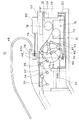
建屋に設置されたトラス12の上階側端部にある機械室14には、エスカレータ10を駆動するための駆動装置16が設けられている。この駆動装置16は、駆動モータ18、駆動モータ18の出力軸に接続された減速機20、駆動モータ18と減速機20との間に設けられたブレーキを有している。減速機20の出力軸には、駆動小スプロケット22が取り付けられている。一方、駆動軸24には、不図示の駆動大スプロケットが取り付けられ、前記した駆動小スプロケット22と駆動大スプロケットには、無端の駆動チェーン26が掛け渡されている。
A
駆動軸24の両端には、左右一対の踏段スプロケット28,28が取り付けられている。また、トラス12の下階側には不図示の左右一対の踏段スプロケットが取り付けられ、上階側の踏段スプロケット28,28との間に無端の踏段チェーン30,30が掛け渡されている。この左右一対の踏段チェーン30,30の間には踏段32が複数取り付けられている。
A pair of left and
踏段32には、前車輪34と後車輪36とがそれぞれ設けられ、それぞれ異なる不図示のガイドレールに沿って移動自在である。
The
機械室14内部には、前記した駆動装置16と、駆動軸24に取り付けられた左右一対の踏段スプロケット28、駆動大スプロケットが配置されている。
Inside the
(2)エスカレータ10の電源系、制御系の配線
エスカレータ10の電源系と制御系の配線について図2〜図5に基づいて説明する。
(2) Power supply system and control system wiring of
機械室14の端にある側面のトラス12には、接続端子箱38と電源系の制御装置(以下、「電源装置」という)39が並んで取り付けられている。
A
電源装置39には、駆動モータ18の電源が接続され、この電源装置39から駆動モータ18に電源が供給される。また、電源装置39からの駆動モータ18を制御するための制御系の配線が、接続端子箱38に接続されている。
The
接続端子箱38には、上記した駆動モータ18からの制御系の配線、安全スイッチからの配線等の制御系の配線が施されている。また、制御系の制御装置40と接続するための点検ケーブル42と運転ケーブル44とが引き出されている。
The
接続端子箱38から引き出された運転ケーブル44は、機械室14の底面を通って踏段スプロケット28によって踏段32が折り返される部分の内側の空間まで引き出されている。そしてこの運転ケーブル44の先端部にはコネクタ44aが取り付けられ、この折り返される空間の位置でトラス12のフレームに固定されている。
The
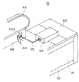
点検ケーブル42は、接続端子箱38から引き出された後に機械室14の底面、側面を通って、機械室14の上外方に引き出され、手すり46の下部にあるスカートガード48に設けられたコネクタ42aまで延びている。このコネクタ42aは、第三者が簡単に触れることができないようにするため、開閉自在なカバー50が、図3に示すように設けられている。
The
制御装置40は、エスカレータ10の通常運転中は、前記した踏段32の折り返し部分の内側の空間である第1配置場所に配置されている。すなわち、この位置にあるトラス12のフレームに固定されている。また、点検運転を行う場合には、機械室14の天井面の上部にある乗降板52上の第2配置場所に配置する。これについては後から詳しく説明する。
During the normal operation of the
(3)制御装置40の構造
次に、制御装置40の構造について図4及び図5に基づいて説明する。
(3) Structure of
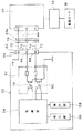
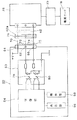
制御装置40は、コンピュータよりなる制御部54、液晶表示装置などよりなる表示部56、スイッチなどよりなる操作部58、外部と接続するための接続回路60とを有し、制御装置40は、作業者によって持ち運びができる。
The
制御装置40のケーシングの表面にある接続部62には、電源端子64、運転端子66、点検端子68が設けられている。電源端子64、運転端子66、点検端子68には、それぞれ電源ケーブル70、運転ケーブル72、点検ケーブル74からなる制御ケーブル75が引き出され、その先端には接続端子76が設けられている。
A
電源端子64には、電源ケーブル70を介して+Vボルトの電源が供給される。
The
運転端子66、点検端子68は、それぞれ通常運転信号、点検信号が入出力される。運転端子66と点検端子68には接続回路60に接続されている。接続回路60内部には、それぞれ通常運転用光フォトカプラー78と点検用光フォトカプラー84が内蔵され、制御部54を保護するために絶縁状態で運転信号と点検信号を入出力する。
The
(4)制御装置40の配置場所
次に、上記で説明した制御装置40の通常運転時と点検運転時の配置場所について説明する。
(4) Location of
まず、エスカレータ10の通常運転時における制御装置40の配置について説明する。通常運転時においては、制御装置40は図1に示すように、踏段32の折り返し部分の内側の空間である第1配置場所のトラス12のフレームに固定する。そして、作業者は、図4に示すように、制御ケーブル75の接続端子76と運転ケーブル44のコネクタ44aとを接続し、接続端子箱38から延びている運転ケーブル44と制御ケーブル75とを接続する。これによって、制御装置40は、エスカレータ10を通常運転のための制御ができる。この通常運転時には制御装置40は踏段32の折り返し部分の空間に配置されているため、制御装置40の寸法が大きくなっても、機械室14のスペースを取ることなく、機械室14を小さくできる。
First, the arrangement of the
次に、エスカレータ10の点検運転時における制御装置40の配置について説明する。エスカレータ10を点検する場合には、まず、作業者が折り返し部分にある踏段32を取り外し、制御装置40を折り返し部分の空間から持ち出して、乗降板52の上に載置する。そして、作業者は、制御ケーブル75の接続端子76と点検ケーブル42のコネクタ42aを接続し、接続端子箱38から延びている点検ケーブル42と制御装置40の制御ケーブル75が接続する。これによって、作業者は制御装置40の表示部56を見ながら操作部58を操作して、エスカレータ10を点検運転を行うことができる。この場合に作業者は、機械室14の内部に入ることなく安全で作業を行い易い。
Next, arrangement | positioning of the
(5)制御装置40の制御状態
次に、制御装置40の制御状態について図6に基づいて説明する。
(5) Control State of
制御装置40が、接続端子箱38の点検ケーブル42、又は、運転ケーブル44に接続されているとする。
It is assumed that the
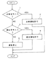
ステップ1において、制御装置40は、点検信号が入力されたか否かを判断し、点検信号が入力されていれば、ステップ2に進み、入力していなければステップ3に進む。
In
ステップ2において、点検信号が入力しているため、制御装置40は点検運転を許可し終了する。
In
ステップ3において、点検信号が入力せず、運転信号が入力していればステップ4に進み、運転信号が入力していなければステップ5に進む。
In
ステップ4において、運転信号が入力しているため、制御装置40は通常運転を許可し終了する。
In
ステップ5において、制御装置40は点検信号及び運転信号の両方とも入力していないため、エスカレータ10の運転を禁止し終了する。
In
このように、制御装置40は、点検信号又は運転信号が入力しているか否かで、点検運転か通常運転かを判断できる。
As described above, the
(6)効果
本実施例によれば、通常運転時においては、制御装置40は踏段32の折り返し部分の内側の空間に配置されているため、機械室14のスペースを取ることなく、機械室14のスペースを小さくできる。
(6) Effect According to the present embodiment, the
また、点検運転時には制御装置40を機械室14の外側に取り出して作業者が点検を行うことができるため、点検作業を行い易く作業者にとっても安全である。
Further, during the inspection operation, the
上記実施例ではエスカレータ10で説明したが、これに代えて動く歩道であってもよい。
Although the
また、点検運転時において制御装置40を乗降板52の上に載置したが、これに限らず、機械室14の外部で作業者が作業を行い易い位置であれば制御装置40をどの位置に配置してもよい。
Moreover, although the
また、上記実施例では運転ケーブル44のコネクタ44aを保護するためにカバー50を設けたが、このカバー50を設けなくてもよい。
Moreover, in the said Example, although the
また、このコネクタ44aの位置は、スカートガード48の部分に限らず、制御装置40の接続端子76が接続し易い位置であればどの位置であってもよいが、乗客が操作できないような位置に設けておくのが好ましい。
The position of the
上記では本発明の一実施形態を説明したが、この実施形態は、例として提示したものであり、発明の範囲を限定することは意図していない。これら新規な実施形態は、その他の様々な形態で実施されることが可能であり、発明の主旨を逸脱しない範囲で、種々の省略、置き換え、変更を行うことができる。これら実施形態やその変形は、発明の範囲や要旨に含まれるとともに、特許請求の範囲に記載された発明とその均等の範囲に含まれる。 Although one embodiment of the present invention has been described above, this embodiment is presented as an example and is not intended to limit the scope of the invention. These novel embodiments can be implemented in various other forms, and various omissions, replacements, and changes can be made without departing from the spirit of the invention. These embodiments and modifications thereof are included in the scope and gist of the invention, and are included in the invention described in the claims and the equivalents thereof.
10・・・エスカレータ、12・・・トラス、14・・・機械室、16・・・駆動装置、24・・・駆動軸、32・・・踏段、38・・・接続端子箱、40・・・制御装置、42・・・点検ケーブル、44・・・運転ケーブル、52・・・乗降板
DESCRIPTION OF
Claims (7)
前記駆動装置と駆動チェーンによって連結された駆動スプロケットと、
前記駆動スプロケットと共に回転する踏段スプロケットと、
前記踏段スプロケットに掛け渡された無端の踏段チェーンと、
前記踏段チェーンに取り付けられた複数の踏段と、
前記駆動装置を制御する制御装置と、
を有する乗客コンベアにおいて、
前記機械室内にある第1配置場所に前記制御装置を配置したときに、前記駆動装置と接続するための通常運転用の第1ケーブルと、
前記機械室外にある第2配置場所に前記制御装置を配置したときに、前記駆動装置と接続するための点検運転用の第2ケーブルと、
を有することを特徴とする乗客コンベア。 A drive device including a drive motor disposed in the machine room;
A drive sprocket connected by the drive device and a drive chain;
A step sprocket that rotates with the drive sprocket;
An endless step chain spanned over the step sprocket;
A plurality of steps attached to the step chain;
A control device for controlling the driving device;
In a passenger conveyor having
A first cable for normal operation for connecting to the drive device when the control device is arranged at a first arrangement location in the machine room;
A second cable for inspection operation for connecting to the drive device when the control device is arranged at a second arrangement location outside the machine room;
Passenger conveyor characterized by having.
ことを特徴とする請求項1に記載の乗客コンベア。 In the vicinity of the second arrangement place, a connection portion for connecting the second cable and the control device is provided.
The passenger conveyor according to claim 1.
ことを特徴とする請求項2に記載の乗客コンベア。 A cover is provided on the connection part,
The passenger conveyor according to claim 2.
ことを特徴とする請求項1乃至3のいずれか一項に記載の乗客コンベア。 The external appearance of the first cable is different from the external appearance of the second cable.
The passenger conveyor according to any one of claims 1 to 3, wherein
ことを特徴とする請求項1乃至4のいずれか一項に記載の乗客コンベア。 When the second cable is connected, the control device prohibits the normal operation and performs control only for the inspection operation.
The passenger conveyor according to any one of claims 1 to 4, wherein the passenger conveyor is provided.
ことを特徴とする請求項1乃至5のいずれか一項に記載の乗客コンベア。 The first arrangement place where the control device is arranged is a space inside a portion where the step chain is folded back by the step sprocket.
The passenger conveyor according to any one of claims 1 to 5, characterized in that.
ことを特徴とする請求項1乃至6のいずれか一項に記載の乗客コンベア。 The second arrangement place where the control device is arranged is on a boarding / alighting plate located on a ceiling surface of the machine room,
The passenger conveyor according to any one of claims 1 to 6, characterized by the above.
Priority Applications (1)
| Application Number | Priority Date | Filing Date | Title |
|---|---|---|---|
| JP2011004186A JP2012144335A (en) | 2011-01-12 | 2011-01-12 | Passenger conveyor |
Applications Claiming Priority (1)
| Application Number | Priority Date | Filing Date | Title |
|---|---|---|---|
| JP2011004186A JP2012144335A (en) | 2011-01-12 | 2011-01-12 | Passenger conveyor |
Publications (1)
| Publication Number | Publication Date |
|---|---|
| JP2012144335A true JP2012144335A (en) | 2012-08-02 |
Family
ID=46788335
Family Applications (1)
| Application Number | Title | Priority Date | Filing Date |
|---|---|---|---|
| JP2011004186A Pending JP2012144335A (en) | 2011-01-12 | 2011-01-12 | Passenger conveyor |
Country Status (1)
| Country | Link |
|---|---|
| JP (1) | JP2012144335A (en) |
-
2011
- 2011-01-12 JP JP2011004186A patent/JP2012144335A/en active Pending
Similar Documents
| Publication | Publication Date | Title |
|---|---|---|
| JP2507670B2 (en) | Passenger conveyor | |
| JP2011178496A (en) | Control device for elevator | |
| JP2014210631A (en) | Passenger conveyor | |
| JP2001220078A (en) | Elevator repair method | |
| JP2017081661A (en) | Passenger conveyor | |
| JP5805508B2 (en) | Elevator equipment | |
| JP2012144335A (en) | Passenger conveyor | |
| CN107098254A (en) | The maintenance inspection system of passenger conveyors | |
| JP2016150815A (en) | Passenger conveyor | |
| CN104817007B (en) | Passenger conveying device | |
| KR102569287B1 (en) | Passenger conveyor renewal method | |
| KR102381875B1 (en) | elevator platform control panel | |
| CN103420239B (en) | Inspection apparatus for double-deck elevator | |
| CN106163960A (en) | The pit access apparatus of elevator | |
| CN101898716A (en) | Drives for passenger conveyors | |
| JPWO2019224882A1 (en) | How to renew the passenger conveyor | |
| JP2013129524A (en) | Safety device for passenger conveyor | |
| JP4355163B2 (en) | Renewal method of passenger conveyor | |
| KR101200064B1 (en) | Display system for Screen door | |
| JP7395699B1 (en) | passenger conveyor display device | |
| JP2016050062A (en) | Passenger conveyor | |
| CN203976305U (en) | Raw material delivery safety interlock system | |
| JP2004026356A (en) | Passenger conveying device | |
| JP7404565B1 (en) | Passenger conveyor emergency stop switch device | |
| JP7387857B1 (en) | Passenger conveyor control device |