JP2012144288A - Impact resistive ptp package - Google Patents
Impact resistive ptp package Download PDFInfo
- Publication number
- JP2012144288A JP2012144288A JP2011005600A JP2011005600A JP2012144288A JP 2012144288 A JP2012144288 A JP 2012144288A JP 2011005600 A JP2011005600 A JP 2011005600A JP 2011005600 A JP2011005600 A JP 2011005600A JP 2012144288 A JP2012144288 A JP 2012144288A
- Authority
- JP
- Japan
- Prior art keywords
- impact
- ptp package
- recess
- buffer
- opening
- Prior art date
- Legal status (The legal status is an assumption and is not a legal conclusion. Google has not performed a legal analysis and makes no representation as to the accuracy of the status listed.)
- Pending
Links
- 239000011347 resin Substances 0.000 claims abstract description 36
- 229920005989 resin Polymers 0.000 claims abstract description 36
- 239000007787 solid Substances 0.000 claims abstract description 25
- 230000004308 accommodation Effects 0.000 claims description 22
- 238000004806 packaging method and process Methods 0.000 claims description 7
- 239000011343 solid material Substances 0.000 claims description 7
- 239000000463 material Substances 0.000 abstract description 11
- 238000009863 impact test Methods 0.000 description 7
- 230000035939 shock Effects 0.000 description 6
- 238000007789 sealing Methods 0.000 description 5
- 239000000126 substance Substances 0.000 description 5
- 230000000052 comparative effect Effects 0.000 description 4
- 239000004743 Polypropylene Substances 0.000 description 3
- XAGFODPZIPBFFR-UHFFFAOYSA-N aluminium Chemical compound [Al] XAGFODPZIPBFFR-UHFFFAOYSA-N 0.000 description 3
- 229910052782 aluminium Inorganic materials 0.000 description 3
- 235000013305 food Nutrition 0.000 description 3
- -1 polypropylene Polymers 0.000 description 3
- 229920001155 polypropylene Polymers 0.000 description 3
- BZHJMEDXRYGGRV-UHFFFAOYSA-N Vinyl chloride Chemical compound ClC=C BZHJMEDXRYGGRV-UHFFFAOYSA-N 0.000 description 2
- 239000003814 drug Substances 0.000 description 2
- 239000011888 foil Substances 0.000 description 2
- 238000012986 modification Methods 0.000 description 2
- 230000004048 modification Effects 0.000 description 2
- 238000000465 moulding Methods 0.000 description 2
- 230000002093 peripheral effect Effects 0.000 description 2
- 241001391944 Commicarpus scandens Species 0.000 description 1
- 239000006096 absorbing agent Substances 0.000 description 1
- 230000003139 buffering effect Effects 0.000 description 1
- 239000002775 capsule Substances 0.000 description 1
- 125000004122 cyclic group Chemical group 0.000 description 1
- 210000005069 ears Anatomy 0.000 description 1
- 230000000694 effects Effects 0.000 description 1
- 238000005516 engineering process Methods 0.000 description 1
- 238000000034 method Methods 0.000 description 1
- 239000000565 sealant Substances 0.000 description 1
- 238000009495 sugar coating Methods 0.000 description 1
Images


Landscapes
- Buffer Packaging (AREA)
- Packages (AREA)
Abstract
Description
本発明は、錠剤等の固形物を収容するPTP包装体とこれに用いる樹脂シートに関し、さらに詳しくは、落下による衝撃を良好に吸収でき、収容された固形物の破損を低減できるうえ、安価に実施でき、しかも包装体全体をコンパクトに維持できる、耐衝撃性PTP包装体とこれに用いる樹脂シートに関する。 The present invention relates to a PTP package that contains solids such as tablets and a resin sheet used therefor, and more specifically, it can absorb shock caused by dropping well, can reduce damage to the contained solids, and is inexpensive. The present invention relates to an impact-resistant PTP package and a resin sheet used therefor that can be implemented and can maintain the entire package compact.
医薬品や食品等の包装分野においては、錠剤、カプセル等や、粒状の食品等を包装するためにPTP(Press Through Pack)包装体が広く用いられている。このPTP包装体は、硬質の塩化ビニル(PVC)シートや無延伸ポリプロピレン(CPP)シート等の樹脂シートに多数の収容凹部を形成し、この収容凹部に錠剤等の固形物を収納した後、収容凹部の開口部を、ヒートシール剤が塗布されたアルミニウム箔や紙よりなる蓋材で覆ってある。そして上記の収容凹部の底部を蓋材側へ押すと、上記の固形物がこの蓋材を押し破って取り出される。 In the packaging field of pharmaceuticals and foods, PTP (Press Through Pack) packages are widely used for packaging tablets, capsules, granular foods, and the like. This PTP package is formed by forming a large number of receiving recesses in a resin sheet such as a hard vinyl chloride (PVC) sheet or an unstretched polypropylene (CPP) sheet, and storing a solid material such as a tablet in the receiving recess. The opening of the recess is covered with a lid made of aluminum foil or paper coated with a heat sealant. And if the bottom part of said accommodating recessed part is pushed to the cover material side, said solid substance will be pushed through this cover material, and will be taken out.
上記のPTP包装体は、固形物が個別に収容されているので、搬送時などに固形物同士が衝突する虞がないうえ、所望の収容凹部のみを開封して必要個数の固形物を容易に取り出せる利点がある。
しかしながら、このPTP包装体を落下させた場合などは、上記の樹脂シートや蓋材を介し固形物が大きな衝撃を受けて破損する場合がある。特に錠剤が糖衣等でコーティングされていない素錠にあっては、固形物の強度が低いので上記の衝撃により破損しやすく、その素錠が乾燥錠剤である場合や、口腔内崩壊錠のように硬度が低い場合は、破損する虞が一層高い。
In the above PTP package, since solids are individually accommodated, there is no risk of solids colliding with each other at the time of transportation, and only a desired accommodating recess is opened to easily obtain the required number of solids. There is an advantage that can be taken out.
However, when this PTP package is dropped, the solid matter may be damaged by receiving a large impact through the resin sheet or the lid. Especially in the case of uncoated tablets that are not coated with sugar coating etc., the strength of the solid matter is low, so it is easy to break due to the impact described above, and when the uncoated tablets are dry tablets, If the hardness is low, the risk of breakage is even higher.
上記の問題点を解消するため、従来、上記の蓋材の、収容凹部側表面に熱封緘性樹脂層を凹凸状に設けたものが提案されている(特許文献1参照、以下、従来技術1という。)。また、PTP包装体の長手方向の端部に、収容凹部が設けられていない耳部を長く形成したものも提案されている(特許文献2参照、以下、従来技術2という。)。
In order to solve the above-described problems, conventionally, a lid material in which a heat-sealing resin layer is provided in an uneven shape on the surface of the accommodation recess has been proposed (see
しかしながら、上記の従来技術1では、特定高さの凹凸となるように形成した熱封緘性樹脂層を蓋材の片面に形成しなければならず、操作が煩雑でコスト高になる問題がある。しかも上記の熱封緘性樹脂層は、蓋材に形成されていることから、PTP包装体が落下した際に樹脂シート側から着地すると、この熱封緘性樹脂層では上記の固形物が受ける衝撃を充分に緩衝できない問題もある。
However, in the above-described
一方、上記の従来技術2では、PTP包装体の長手方向端部に耳部を長く形成することから、PTP包装体の外形寸法が大きくなり、これを収容する箱体なども大形となって、資材コストが高くつき安価に実施できないばかりか、製品容積が大きくなるため、搬送時や保管時などに大きなスペースを必要とする問題がある。
また、このPTP包装体が落下する際に、蓋材を下方にした姿勢で落下する場合は、耳部から着地すると緩衝できるが、樹脂シートを下方にした姿勢で落下すると、収容凹部が突出しているため、耳部よりも先に収容凹部が着地する場合がある。この場合には、上記の耳部では、収容凹部内の固形物に伝わる衝撃を緩衝できない問題がある。特に、着地面に起伏がある場合は、PTP包装体の中間部分で着地する場合があり、上記の耳部ではその着地時の衝撃を緩衝することができず、収容された固形物が破損する虞がある。
On the other hand, in the above-described
In addition, when this PTP package is dropped, if it falls in a posture with the lid facing downward, it can be buffered by landing from the ear, but if it falls in a posture with the resin sheet lowered, the housing recess protrudes. Therefore, the housing recess may land before the ear. In this case, there is a problem that the above-mentioned ear portion cannot buffer the impact transmitted to the solid matter in the housing recess. In particular, if there is a undulation on the ground, it may land at the middle part of the PTP package, and the above-mentioned ear part cannot buffer the impact at the time of landing, and the contained solid matter is damaged. There is a fear.
本発明の技術的課題は上記の問題点を解消し、落下による衝撃を良好に吸収でき、収容された固形物の破損を低減できるうえ、安価に実施でき、しかも包装体全体をコンパクトに維持できる、耐衝撃性PTP包装体とこれに用いる樹脂シートを提供することにある。 The technical problem of the present invention is to solve the above-mentioned problems, to absorb the impact caused by dropping well, to reduce the damage of the contained solid matter, to be carried out at a low cost, and to keep the whole package compact. An object of the present invention is to provide an impact-resistant PTP package and a resin sheet used therefor.
本発明は上記の課題を解決するために、例えば本発明の実施の形態を示す図1から図7に基づいて説明すると、次のように構成したものである。
すなわち、本発明1は耐衝撃性PTP包装体に関し、樹脂シート(2)の片面に収容凹部(4)を凹設し、その収容凹部(4)内の収容空間(5)に固形物(6)を収容したのち、この収容凹部(4)の開口部(7)をシート状の蓋材(3)で蓋したPTP包装体であって、上記の収容凹部(4)の壁部のうち、上記の収容空間(5)を挟んで上記の開口部(7)とは反対側の壁部(8)に、凸部と凹部との少なくともいずれかを備える緩衝部(10)を形成したことを特徴とする。
In order to solve the above problems, the present invention will be described as follows, for example, based on FIGS. 1 to 7 showing an embodiment of the present invention.
That is, the
また本発明2は耐衝撃性PTP包装体用樹脂シートに関し、固形物(6)を収容するための収容凹部(4)を片面に凹設した、上記の本発明1の耐衝撃性PTP包装体(1)に用いる樹脂シートであって、
上記の収容凹部(4)の壁部(8)に、凸部と凹部との少なくともいずれかを備える上記の緩衝部(10)を形成したことを特徴とする。
In addition, the
The buffer portion (10) including at least one of a convex portion and a concave portion is formed on the wall portion (8) of the accommodating concave portion (4).
上記のPTP包装体には、上記の収容空間を挟んで開口部とは反対側の壁部に緩衝部が形成してあるので、このPTP包装体が樹脂シート側を下方にした姿勢で落下すると、上記の収容凹部は上記の緩衝部を形成した壁部から着地する。このとき、上記の収容凹部内の固形物は、収容凹部の内面に支持された状態となっており、その支持部位とPTP包装体の接地部位とは、上記の緩衝部を介して、収容凹部の壁部の肉厚よりも大きい寸法で離隔している。そしてこの緩衝部が変形することにより、上記の着地時の衝撃が良好に緩衝される。しかも、上記の緩衝部は収容凹部の壁部に形成されるので、その収容凹部の成型金型を変更するだけで簡単に実施できるうえ、前記の従来技術2と異なって、PTP包装体の長さを大きくする必要がない。
Since the buffer portion is formed on the wall portion on the opposite side to the opening portion with the accommodation space sandwiched in the PTP package body, when the PTP package body is dropped with the resin sheet side downward, The accommodation recess is landed from the wall portion on which the buffer portion is formed. At this time, the solid matter in the housing recess is in a state of being supported by the inner surface of the housing recess, and the support portion and the grounding portion of the PTP package are placed in the housing recess via the buffer portion. Are separated by a dimension larger than the wall thickness of the wall. And since this buffer part deform | transforms, the impact at the time of said landing is buffered favorably. In addition, since the buffer portion is formed on the wall portion of the housing recess, the buffer portion can be easily implemented by simply changing the molding die of the housing recess, and unlike the
ここで、自容器の固形物とは、錠剤等のように、一定の形状を備えたブロック状もしくは塊状に形成されているものをいう。
また上記の緩衝部は、収容凹部の壁部に形成されて、落下して着地する際などの衝撃を良好に緩衝できればよく、特定の形状や構造のものに限定されない。例えば上記の緩衝部は、収容空間から外方へ突出した凸部や、収容空間に向かって凹設された凹部を備える形状にすることができる。
Here, the solid material of the container means a product formed in a block shape or a lump shape having a certain shape, such as a tablet.
Moreover, said buffer part should just be formed in the wall part of an accommodation recessed part, and can buffer the impact at the time of falling and landing, etc., and is not limited to the thing of a specific shape and structure. For example, the above-mentioned buffer part can be made into the shape provided with the convex part which protruded outward from the accommodation space, and the crevice provided in the storage space.
上記の緩衝部の凸部や凹部は、部分球面状など、中央部が盛り上がった伏椀状に形成してあると、簡単な形状であるので容易に形成でき、安価に実施できるうえ、上記の衝撃を良好に緩衝できて好ましい。
また上記の緩衝部は、環状の凸部や凹溝に形成することができる。この場合は、緩衝部を広い面積に形成できるので、その凸部や凹部の突出高さを低く抑えることができ、PTP包装体全体を一層コンパクトに維持しても良好に緩衝できて好ましい。
とくに緩衝部を環状に形成した場合、同心円状に複数形成してあると、これらの緩衝部により一層良好に衝撃を緩衝できてより好ましい。
The convex part and concave part of the above-mentioned buffer part can be easily formed because it is a simple shape if it is formed in a prone shape with a raised central part such as a partial spherical shape, and can be implemented at low cost, and The shock can be satisfactorily buffered, which is preferable.
Moreover, said buffer part can be formed in a cyclic | annular convex part or a ditch | groove. In this case, since the buffer part can be formed in a wide area, the protruding height of the convex part and the concave part can be kept low, and even if the entire PTP package is kept more compact, it can be satisfactorily buffered, which is preferable.
In particular, when the buffer portion is formed in an annular shape, it is more preferable that a plurality of concentric circles are formed because the shock can be more effectively buffered by these buffer portions.
上記の緩衝部は、特定の大きさに限定されず、収容凹部の大きさや樹脂シートの厚み、収容される固形物の寸法や硬度などに応じて、上記の衝撃を良好に緩衝できる寸法に設定される。例えば、緩衝部の平面視中央を通過するいずれかの断面において、この緩衝部の幅が上記の開口部の開口幅の30%以上であると、上記の衝撃を良好に緩衝できて好ましい。 The above-mentioned buffer portion is not limited to a specific size, and is set to a size capable of satisfactorily buffering the above impact according to the size of the housing recess, the thickness of the resin sheet, the size and hardness of the solid material to be housed, etc. Is done. For example, in any cross section that passes through the center of the buffer portion in plan view, it is preferable that the width of the buffer portion is 30% or more of the opening width of the opening portion because the above shock can be buffered well.
具体的には、例えば図1と図2に示すように、平面視において上記の収容凹部と緩衝部がいずれも円形に形成され、上記の緩衝部が伏椀状である場合、その緩衝部の外径は、収容凹部の開口部の内径の、好ましくは30%以上の寸法に設定され、より好ましくは30〜70%の寸法に設定される。この場合、この伏椀状緩衝部の高さは、収容凹部の深さに対し、好ましくは10〜40%に設定され、より好ましくは15〜40%程度の寸法に設定される。 Specifically, for example, as shown in FIGS. 1 and 2, when the receiving recess and the buffer portion are both formed in a circular shape in plan view, and the buffer portion has a prone shape, The outer diameter is preferably set to a dimension of 30% or more, more preferably 30 to 70%, of the inner diameter of the opening of the housing recess. In this case, the height of the prone buffer portion is preferably set to 10 to 40%, more preferably about 15 to 40%, with respect to the depth of the housing recess.
なお、上記の緩衝部は、平面視で周縁部を円形に形成すると、容易に形成できて好ましいが、例えば収容凹部が平面視で楕円形や長円形である場合などは、緩衝部の周縁部をこれと相似形に形成することも可能であり、或いはこれらとは相違した任意の形状に形成することも可能である。 In addition, it is preferable to form the peripheral portion in a circular shape in a plan view because the buffer portion can be easily formed. However, for example, when the accommodating recess is an ellipse or an oval in a plan view, the peripheral portion of the buffer portion Can be formed in a similar shape, or can be formed in any shape different from these.
本発明の耐衝撃性PTP包装体と耐衝撃性PTP包装体用樹脂シートは、上記のように構成され作用することから、次の効果を奏する。 Since the impact-resistant PTP packaging body and the resin sheet for impact-resistant PTP packaging body of the present invention are configured and act as described above, the following effects can be obtained.
(1)上記の収容凹部には、収容空間を挟んで開口部とは反対側の壁部に緩衝部が形成してあるので、このPTP包装体が樹脂シート側を下方にして落下した場合など、樹脂シート側から衝撃が加わった場合に、その衝撃を上記の緩衝部で良好に緩衝することができ、収容凹部に収容された固形物の破損を効果的に低減することができる。 (1) Since the buffer portion is formed in the wall portion on the opposite side of the opening portion with respect to the storage space in the above-mentioned storage recess portion, when this PTP package is dropped with the resin sheet side downward, etc. When an impact is applied from the resin sheet side, the impact can be satisfactorily buffered by the above-described buffer portion, and the breakage of the solid matter housed in the housing recess can be effectively reduced.
(2)上記の緩衝部は収容凹部の壁部に形成されるので、その収容凹部の成型金型を変更するだけで、PTP包装体の幅や長さを大きくする必要がなく、安価に実施できるうえ、包装体全体をコンパクトに維持でき、搬送時や保管時などに、無駄に大きなスペースを必要とすることがない。 (2) Since the buffer portion is formed on the wall portion of the housing recess, it is not necessary to increase the width or length of the PTP package simply by changing the molding die of the housing recess, and the cost is low. In addition, the entire package can be kept compact, and a large space is not required unnecessarily during transportation or storage.
以下、本発明の実施の形態を図面に基づき説明する。なお、以下の各実施形態では、説明を容易にするため、樹脂シートが蓋材の下方に配置された姿勢で説明するが、本発明のPTP包装体は、この姿勢や他の特定の姿勢に限定されるものではない。 Hereinafter, embodiments of the present invention will be described with reference to the drawings. In each of the following embodiments, for ease of explanation, the resin sheet is described in a posture arranged below the lid, but the PTP package of the present invention is in this posture or other specific posture. It is not limited.
図1と図2は本発明の第1実施形態の耐衝撃性PTP包装体(1)を示している。
図1と図2に示すようにこの耐衝撃性PTP包装体(1)は、例えば無延伸ポリプロピレン(CPP)シート等の樹脂シート(2)と、アルミニウム箔等の蓋材(3)とを備えている。この樹脂シート(2)の片面には複数の収容凹部(4)が凹設してあり、この収容凹部(4)内の収容空間(5)に固形物である錠剤(6)を収容したのち、この収容凹部(4)の開口部(7)を上記の蓋材(3)で保密状に蓋してある。
1 and 2 show an impact-resistant PTP package (1) according to a first embodiment of the present invention.
As shown in FIGS. 1 and 2, the impact-resistant PTP package (1) includes a resin sheet (2) such as an unstretched polypropylene (CPP) sheet, and a lid (3) such as an aluminum foil. ing. A plurality of receiving recesses (4) are formed on one side of the resin sheet (2), and after the tablet (6), which is a solid material, is stored in the receiving space (5) in the receiving recess (4). The opening (7) of the housing recess (4) is covered with the lid (3) in a tightly sealed manner.
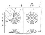
上記の収容凹部(4)は、上記の錠剤(6)の形状に応じて、例えば略円錐台状に形成してある。図2に示すように、この収容凹部(4)には、上記の収容空間(5)を挟んで上記の開口部(7)とは反対側の壁部、即ち底部(8)に、収容空間(5)の外方である下方に向かって突出した緩衝部(10)が、この底部(8)と一体に形成してある。この緩衝部(10)は、部分球面からなる伏椀状の凸部(11)に形成してあり、図1に示すように、平面視で収容凹部(4)と同心円状に形成してある。 The accommodating recess (4) is formed in, for example, a substantially truncated cone shape according to the shape of the tablet (6). As shown in FIG. 2, in the housing recess (4), the housing space is formed in a wall portion opposite to the opening (7) across the housing space (5), that is, in the bottom portion (8). A shock-absorbing portion (10) projecting downward, which is the outside of (5), is formed integrally with the bottom portion (8). This buffer part (10) is formed in a protrusive convex part (11) consisting of a partial spherical surface, and is formed concentrically with the accommodating concave part (4) in plan view as shown in FIG. .
上記の収容凹部(4)と緩衝部(10)の各寸法は、上記の錠剤(6)に応じて設定される。
例えば、上記の錠剤の直径(D)が8mmである場合、上記の開口部(7)の内径(W)が10.5mmに設定され、伏椀状凸部(11)の平面視での外径(w1)が5.0mmに設定されている。従って上記の緩衝部(10)の平面視中央を通過する断面、即ち縦断面において、この緩衝部(10)の幅が上記の開口部(7)の開口幅の47.6%に設定されている。
一方、上記の開口部(7)と底部(8)との間隔、即ち収容凹部(4)の深さ(H)は、上記の緩衝部(10)を形成していない場合は4.7mmに設定され、これに対し伏椀状凸部(11)の突出高さ(h1)は1.3mmに設定されている。従って、緩衝部(10)の突出高さは収容凹部の深さ(H)の27.7%に設定されている。
Each dimension of said accommodation recessed part (4) and buffer part (10) is set according to said tablet (6).
For example, when the diameter (D) of the tablet is 8 mm, the inner diameter (W) of the opening (7) is set to 10.5 mm, and the outer surface in the plan view of the prone convex portion (11) is set. The diameter (w1) is set to 5.0 mm. Therefore, the width of the buffer portion (10) is set to 47.6% of the opening width of the opening (7) in the section passing through the center of the buffer portion (10) in plan view, that is, in the longitudinal section. Yes.
On the other hand, the distance between the opening (7) and the bottom (8), that is, the depth (H) of the accommodating recess (4) is 4.7 mm when the buffer (10) is not formed. On the other hand, the protrusion height (h1) of the prone protrusion (11) is set to 1.3 mm. Therefore, the protruding height of the buffer portion (10) is set to 27.7% of the depth (H) of the receiving recess.
上記の緩衝部(10)である伏椀状凸部(11)の外径(w1)は、錠剤(6)の直径(D)よりも小さく、従って収容凹部(4)内に収容された錠剤(6)は、緩衝部(10)の周囲の、収容空間(5)側の内面に形成された支持部位(17)に支持されている。このPTP包装体(1)が樹脂シート(2)側を下方にして落下した場合、上記の緩衝部(10)の下端に形成された接地部位(18)で着地する。この接地部位(18)と上記の支持部位(17)とは、底部(8)の肉厚よりも大きな寸法で、上下方向に離隔しており、PTP包装体(1)が落下するなどして上記の収容凹部(4)に下方から衝撃を受けると、上記の緩衝部(10)が変形してその衝撃が緩衝され、上記の錠剤(6)の破損が防止される。
上記の錠剤(6)をPTP包装体(1)から取り出す場合は、上記の収容凹部(4)を上記の蓋材(3)側へ押圧して変形させて、上記の錠剤(6)を上記の蓋材(3)側へ押圧する。これによりその蓋材(3)が押し破られて錠剤(6)が取り出される。
The outer diameter (w1) of the prone convex portion (11) which is the buffer portion (10) is smaller than the diameter (D) of the tablet (6), and therefore the tablet accommodated in the accommodating recess (4). (6) is supported by a support portion (17) formed on the inner surface of the accommodation space (5) side around the buffer portion (10). When this PTP package (1) falls with the resin sheet (2) side down, it lands on the ground contact portion (18) formed at the lower end of the buffer (10). The grounding part (18) and the supporting part (17) are larger than the thickness of the bottom part (8) and are separated in the vertical direction, and the PTP package (1) is dropped. When the receiving recess (4) receives an impact from below, the buffer portion (10) is deformed to buffer the impact and prevent the tablet (6) from being damaged.
When taking out said tablet (6) from a PTP package (1), said accommodating recessed part (4) is pressed and deformed to said lid | cover material (3) side, and said tablet (6) is said To the lid (3) side. Thereby, the cover material (3) is pushed through and the tablet (6) is taken out.
図3と図4は本発明の第2実施形態の耐衝撃性PTP包装体(1)を示している。
図3と図4に示すように、この第2実施形態では、収容凹部(4)の底部(8)に、緩衝部(10)として、収容空間(5)から外方へ突出した2つの環状の凸部(12・13)が同心円状に形成してある。
3 and 4 show an impact-resistant PTP package (1) according to a second embodiment of the present invention.
As shown in FIGS. 3 and 4, in the second embodiment, two annular protrusions projecting outward from the accommodation space (5) as a buffer portion (10) are provided at the bottom (8) of the accommodation recess (4). Convex parts (12, 13) are formed concentrically.
上記の内側環状凸部(12)は、外径(w2)が5.25mmに設定してある。上記の第1実施形態と同様、収容凹部(4)の開口部(7)の内径(W)は10.5mmに設定してあるので、この内側環状凸部(12)の外径(w2)は、開口部(7)の内径(W)の50%に設定されている。この内側環状凸部(12)の突出高さ(h2)は、0.5mmに設定してある。第1実施形態と同様、収容凹部(4)の深さ(H)は4.7mmに設定してあるので、上記の内側環状凸部(12)の突出高さ(h2)は、収容凹部(4)の深さ(H)の10.6%に設定されている。
また上記の外側環状凸部(13)は、外径(w3)が9.25mmに設定してある。従ってこの外側環状凸部(13)の外径(W3)は、上記の開口部(7)の内径(W)の88.1%に設定されている。
The inner annular projection (12) has an outer diameter (w2) set to 5.25 mm. As in the first embodiment, the inner diameter (W) of the opening (7) of the housing recess (4) is set to 10.5 mm, so the outer diameter (w2) of the inner annular projection (12). Is set to 50% of the inner diameter (W) of the opening (7). The protrusion height (h2) of the inner annular protrusion (12) is set to 0.5 mm. As in the first embodiment, since the depth (H) of the housing recess (4) is set to 4.7 mm, the protrusion height (h2) of the inner annular projection (12) is set to the housing recess ( It is set to 10.6% of the depth (H) of 4).
The outer annular projection (13) has an outer diameter (w3) set to 9.25 mm. Accordingly, the outer diameter (W3) of the outer annular convex portion (13) is set to 88.1% of the inner diameter (W) of the opening (7).
上記の両環状凸部(12、13)の下面にはそれぞれ接地部位(18)が形成してある。そして、内側環状凸部(12)で囲まれた部分の収容空間(5)に面する内面と、両環状凸部(12・13)間の凹溝部分の収容空間(5)に面する内面とに、それぞれ支持部位(17)が成形してあり、収容凹部(4)に収容された錠剤(6)はこれらの支持部位(17)に安定良く支持される。 Grounding portions (18) are formed on the lower surfaces of the two annular convex portions (12, 13). And the inner surface which faces the accommodation space (5) of the part enclosed by the inner side annular convex part (12), and the inner surface which faces the accommodation space (5) of the recessed groove part between both annular convex parts (12, 13) In addition, the support portions (17) are respectively formed, and the tablet (6) accommodated in the accommodating recess (4) is stably supported by these support portions (17).
次に、上記の第1実施形態と第2実施形態のPTP包装体について、緩衝部を形成していないPTP包装体と比較して、落下時の衝撃試験を実施した。この衝撃試験に用いた、実施例1は上記の第1実施形態で例示した寸法のPTP包装体であり、実施例2は上記の第2実施形態で例示した寸法のPTP包装体である。また比較例1は、上記の実施例1のPTP包装体において緩衝部を省略した状態のPTP包装体である。 Next, the impact test at the time of dropping was implemented about the PTP package of said 1st Embodiment and 2nd Embodiment compared with the PTP package which has not formed the buffer part. Example 1 used in this impact test is a PTP package having the dimensions exemplified in the first embodiment, and Example 2 is a PTP package having the dimensions exemplified in the second embodiment. Comparative Example 1 is a PTP package in a state where the buffer portion is omitted from the PTP package of Example 1 described above.
各PTP包装体は、樹脂シートに厚み0.3mmの無延伸ポリプロピレン(CPP)樹脂シートを用い、蓋材に厚み0.02mmのアルミフィルムを用いた。また各PTP包装体には、それぞれ21個の収容凹部を形成した。
上記の収容凹部には、外径8.0mm、厚み4.0〜4.5mm、質量220mgの素錠を1個ずつ収容した。
In each PTP package, an unstretched polypropylene (CPP) resin sheet having a thickness of 0.3 mm was used as the resin sheet, and an aluminum film having a thickness of 0.02 mm was used as the lid. Each PTP package was formed with 21 accommodating recesses.
One uncoated tablet having an outer diameter of 8.0 mm, a thickness of 4.0 to 4.5 mm, and a mass of 220 mg was housed in the housing recess.
衝撃試験に用いたPTP包装体は、樹脂シート側を対面させて重ねた2枚のPTP包装体を1組とし、これを3組重ねて束ねたものを1試料とした。そして、各実施例、比較例ごとに15の試料を用いて衝撃試験を実施した。従って用いた錠剤は、それぞれ1890錠ずつである。 The PTP package used for the impact test was one set of two PTP packages that were stacked with the resin sheet facing each other, and one set of three bundles bundled together. And the impact test was implemented using 15 samples for every Example and comparative example. Therefore, 1890 tablets are used each.
衝撃試験は、上記の試料を、PTP包装体が水平となる姿勢で、100cmの高さから床面上へ1回自由落下させたとき、3回自由落下させたとき、及び3回自由落下させたのち150cmの高さから床面上へ1回自由落下させたときの、それぞれについて、落下後のPTP包装体内で割れている錠剤の個数を目視で確認し、全錠に対する破損率を算出した。その試験結果を図5の耐衝撃性対比表に示す。 In the impact test, the above-mentioned sample was dropped freely from the height of 100 cm once onto the floor surface when the PTP package was horizontal, when dropped three times, and dropped three times. After that, the number of tablets that were broken in the PTP package after dropping was visually checked for each free fall from the height of 150 cm onto the floor surface, and the damage rate for all tablets was calculated. . The test results are shown in the impact resistance comparison table of FIG.
上記の衝撃試験の結果から明らかなように、本発明の実施例1と実施例2では、比較例1のPTP包装体と比較して、錠剤破損率を大きく低減することができた。 As is clear from the results of the impact test described above, in Example 1 and Example 2 of the present invention, the tablet breakage rate could be greatly reduced as compared with the PTP package of Comparative Example 1.
上記の第2実施形態では、緩衝部(10)として2つの環状凸部(12・13)を形成した。この場合、図4に示すように、内側環状凸部(12)で囲まれた部分は、収容空間(5)に向かって凹設された伏椀状の凹部(15)であり、内・外環状凸部(12・13)の間の部分は、収容空間(5)に向かって凹設された環状の凹溝(16)である、とみることができる。即ち、本発明の上記の緩衝部(10)は、収容空間(5)に向かって凹設された凹部を備えるものであってもよい。 In the second embodiment, the two annular convex portions (12, 13) are formed as the buffer portion (10). In this case, as shown in FIG. 4, the portion surrounded by the inner annular convex portion (12) is a prone concave portion (15) recessed toward the accommodating space (5). The portion between the annular convex portions (12, 13) can be regarded as an annular concave groove (16) recessed toward the accommodation space (5). That is, the buffer portion (10) according to the present invention may include a concave portion that is recessed toward the accommodation space (5).
図6に示す、本発明の第3実施形態では、緩衝部(10)として、伏椀状の凹部(15)と環状の凸部(14)を組み合わせてある。この伏椀状凹部(15)の収容空間(5)側の内面に支持部位(17)が成形してあり、収容凹部(4)内の錠剤(6)はこの支持部位(17)に支持されている。一方、上記の環状凸部(14)の下端に接地部位(18)が形成されており、この接地部位(18)と上記の支持部位(17)とは、収容凹部(4)の底部(8)の肉厚よりも大きい寸法で、上下方向に離隔させてある。 In the third embodiment of the present invention shown in FIG. 6, as the buffer portion (10), a prone concave portion (15) and an annular convex portion (14) are combined. A support portion (17) is formed on the inner surface of the prone recess (15) on the side of the storage space (5), and the tablet (6) in the storage recess (4) is supported by the support portion (17). ing. On the other hand, a grounding part (18) is formed at the lower end of the annular convex part (14), and the grounding part (18) and the support part (17) are connected to the bottom part (8) of the accommodating concave part (4). ) Is larger than the wall thickness and spaced apart in the vertical direction.
上記の各実施形態では、いずれも収容凹部が平面視で円形に形成される場合について説明した。しかし本発明では、収容凹部が他の形状であっても良く、例えば図7に示す他の変形例では、収容凹部(4)が平面視で長円形に形成してある。 In each of the above embodiments, the case has been described in which the housing recess is formed in a circular shape in plan view. However, in the present invention, the housing recess may have another shape. For example, in another modification shown in FIG. 7, the housing recess (4) is formed in an oval shape in plan view.
即ち、図7(a)に示す第4実施形態では、例えば収容される錠剤が平面視で長円形である場合などに対応して、収容凹部(4)が平面視で長円形に形成してある。そしてこの収容凹部(4)の底部(8)に、平面視が長円形の衝撃部(10)が伏椀状に形成してある。
また図7(b)に示す第5実施形態では、平面視で長円形に形成された収容凹部(4)の底部(8)に、平面視が円形の衝撃部(10)を2つ、それぞれ伏椀状に形成してある。
衝撃部の寸法など、その他の構成は上記の第1実施形態と同様であり、同様に作用するので説明を省略する。
That is, in the fourth embodiment shown in FIG. 7 (a), the accommodating recess (4) is formed in an oval shape in plan view, for example, corresponding to the case where the tablet to be accommodated is oval shape in plan view. is there. An impact portion (10) having an oval shape in plan view is formed in a prone shape on the bottom portion (8) of the accommodating recess (4).
Further, in the fifth embodiment shown in FIG. 7 (b), two impact portions (10) having a circular plan view are provided on the bottom portion (8) of the accommodating recess (4) formed in an oval shape in plan view, respectively. It is shaped like a prone.
Other configurations, such as the dimensions of the impact portion, are the same as those in the first embodiment described above and operate in the same manner, so that the description thereof is omitted.
上記の各実施形態で説明した耐衝撃性PTP包装体とこれに用いる樹脂シートは、本発明の技術的思想を具体化するために例示したものであり、各部の形状や寸法、材質、配置構造などは、これらこの実施形態のものに限定されるものではなく、本発明の特許請求の範囲内において種々の変更を加え得るものである。 The impact-resistant PTP package and the resin sheet used therefor described in each of the above-described embodiments are examples for embodying the technical idea of the present invention. These are not limited to those of this embodiment, and various modifications can be made within the scope of the claims of the present invention.
例えば、上記の第1実施形態では1枚の樹脂シートに21個の収容凹部を形成したが、本発明では収容凹部の形成個数や形成位置は、この実施形態のものに限定されない。またこの第1実施形態では、樹脂シートの耳部を過剰に長く形成していないので、PTP包装体全体をコンパクトに形成できて好ましい。しかし本発明のPTP包装体やこれに用いる樹脂シートは、前記の従来技術2のように耳部を長く形成してもよく、この場合は上記の緩衝部と相俟って、錠剤の破損を一層低減できて好ましい。さらに本発明のPTP包装体は、前記の従来技術1の、凹凸状の熱封緘性樹脂層と組み合わせることも可能である。
For example, in the first embodiment, 21 housing recesses are formed in one resin sheet. However, in the present invention, the number and positions of the housing recesses are not limited to those in this embodiment. Moreover, in this 1st Embodiment, since the ear | edge part of the resin sheet is not formed too long, the whole PTP package body can be formed compactly, and it is preferable. However, the PTP package of the present invention and the resin sheet used therefor may have long ears as in the
また、上記の第2実施形態では、緩衝部が2つの環状突部を備える場合について説明した。しかし本発明では収容凹部が平面視でより大形である場合などは、この緩衝部が3重や4重の環状突部を備えることも可能である。 Moreover, said 2nd Embodiment demonstrated the case where a buffer part was provided with two annular protrusions. However, in the present invention, when the accommodating recess is larger in plan view, the buffer portion can be provided with a triple or quadruple annular protrusion.
また、上記の各実施形態では、固形物が錠剤である場合について説明した。しかし本発明のPTP包装体の収容部に収容される固形物は、素錠以外の錠剤はもとより、医薬品以外の固形物であってもよく、その固形物の形状や寸法、成分等は、特定のものに限定されない。
さらに、上記の衝撃試験ではPTP包装体を落下させたが、本発明のPTP包装体に形成した緩衝部は、例えばPTP包装体が他物と衝突した際など、落下以外に起因して受ける衝撃であっても、収容凹部内の固形物が受ける衝撃を良好に緩衝できることは、いうまでもない。
In each of the above embodiments, the case where the solid material is a tablet has been described. However, the solid substance accommodated in the accommodating part of the PTP package of the present invention may be a solid substance other than pharmaceuticals as well as tablets other than uncoated tablets. The shape, dimensions, components, etc. of the solid substance are specified. It is not limited to those.
Furthermore, although the PTP package was dropped in the above-described impact test, the shock absorber formed on the PTP package of the present invention receives an impact caused by something other than dropping, such as when the PTP package collides with another object. Even so, it goes without saying that the shock received by the solid matter in the housing recess can be satisfactorily buffered.
本発明の耐衝撃性PTP包装体とこれに用いる樹脂シートは、落下による衝撃を良好に吸収でき、収容された固形物の破損を低減できるうえ、安価に実施でき、しかも包装体全体をコンパクトに維持できるので、医薬品の錠剤を包装するPTP包装体に特に好適であるが、食品など他の用途の固形物を包装するPTP包装体にも好適である。 The impact-resistant PTP package of the present invention and the resin sheet used therefor can absorb the impact of dropping well, reduce the damage of the contained solid matter, and can be implemented at low cost, and the entire package can be made compact. Since it can be maintained, it is particularly suitable for a PTP package for packaging pharmaceutical tablets, but is also suitable for a PTP package for packaging solids for other uses such as food.
1…PTP包装体
2…樹脂シート
3…蓋材
4…収容凹部
5…収容空間
6…固形物(錠剤)
7…収容凹部(4)の開口部
8…収容空間(5)を挟んで上記の開口部(7)とは反対側の壁部(底部)
10…緩衝部
11…伏椀状の凸部
12…内側環状凸部
13…外側環状凸部
14…環状の凸部
15…伏椀状の凹部
16…環状の凹溝
W…開口部(7)の開口幅(開口部の内径)
w1…伏椀状凸部(11)の幅(凸部の外径)
w2…内側環状凸部(12)幅(凸部の外径)
w3…外側環状凸部(13)幅(凸部の外径)
DESCRIPTION OF
7. Opening of receiving recess (4) 8... Wall (bottom) opposite to opening (7) across holding space (5)
10 ... Buffer part
11 ... Protruding convex part
12 ... Inner annular convex
13 ... Outer annular convex
14… Round convex part
15 ... prone depression
16: annular groove W: opening width of opening (7) (inner diameter of opening)
w1… Width of prone convex (11) (outer diameter of convex)
w2… Inner annular convex part (12) width (external diameter of convex part)
w3… Outer annular convex part (13) Width (outer diameter of convex part)
Claims (7)
上記の収容凹部(4)の壁部のうち、上記の収容空間(5)を挟んで上記の開口部(7)とは反対側の壁部(8)に、凸部と凹部との少なくともいずれかを備える緩衝部(10)を形成したことを特徴とする、耐衝撃性PTP包装体。 An accommodation recess (4) is provided on one side of the resin sheet (2), and the solid (6) is accommodated in the accommodation space (5) in the accommodation recess (4). A PTP package in which the part (7) is covered with a sheet-like lid (3),
Of the wall portions of the housing recess (4), the wall portion (8) on the opposite side of the opening (7) across the housing space (5) has at least one of a convex portion and a recess. An impact-resistant PTP package characterized by forming a buffer portion (10) comprising
上記の収容凹部(4)の壁部(8)に、凸部と凹部との少なくともいずれかを備える上記の緩衝部(10)を形成したことを特徴とする、耐衝撃性PTP包装体用樹脂シート。 A resin sheet for use in the impact-resistant PTP package (1) according to any one of claims 1 to 6, wherein a housing recess (4) for housing the solid material (6) is provided on one side. And
Resistant for impact-resistant PTP packaging, wherein the buffer portion (10) having at least one of a convex portion and a concave portion is formed on the wall portion (8) of the accommodating concave portion (4). Sheet.
Priority Applications (1)
| Application Number | Priority Date | Filing Date | Title |
|---|---|---|---|
| JP2011005600A JP2012144288A (en) | 2011-01-14 | 2011-01-14 | Impact resistive ptp package |
Applications Claiming Priority (1)
| Application Number | Priority Date | Filing Date | Title |
|---|---|---|---|
| JP2011005600A JP2012144288A (en) | 2011-01-14 | 2011-01-14 | Impact resistive ptp package |
Publications (1)
| Publication Number | Publication Date |
|---|---|
| JP2012144288A true JP2012144288A (en) | 2012-08-02 |
Family
ID=46788301
Family Applications (1)
| Application Number | Title | Priority Date | Filing Date |
|---|---|---|---|
| JP2011005600A Pending JP2012144288A (en) | 2011-01-14 | 2011-01-14 | Impact resistive ptp package |
Country Status (1)
| Country | Link |
|---|---|
| JP (1) | JP2012144288A (en) |
Cited By (11)
| Publication number | Priority date | Publication date | Assignee | Title |
|---|---|---|---|---|
| JP2014000980A (en) * | 2012-06-18 | 2014-01-09 | Kanae Co Ltd | PTP package |
| JP2014090831A (en) * | 2012-11-02 | 2014-05-19 | Sumitomo Bakelite Co Ltd | Medicament packaging sheet |
| JP2014169089A (en) * | 2013-03-01 | 2014-09-18 | Ckd Corp | Ptp sheet and producing device thereof |
| JP2016124615A (en) * | 2015-01-08 | 2016-07-11 | 大成化工株式会社 | Ptp package |
| DE102015218216A1 (en) * | 2015-09-22 | 2017-03-23 | Henkel Ag & Co. Kgaa | Blister packaging and method for removing a tablet from the blister pack |
| JP2017178352A (en) * | 2016-03-29 | 2017-10-05 | ニプロ株式会社 | Ptp package body |
| JP2018110678A (en) * | 2017-01-11 | 2018-07-19 | Meiji Seikaファルマ株式会社 | PTP package |
| JP2018150064A (en) * | 2017-03-14 | 2018-09-27 | 能美防災株式会社 | Embossed tape |
| JP2022117576A (en) * | 2021-02-01 | 2022-08-12 | Ckd株式会社 | PTP sheet and PTP packaging machine |
| JP2022124040A (en) * | 2021-02-15 | 2022-08-25 | Ckd株式会社 | Manufacturing method of PTP sheet |
| US12128005B2 (en) | 2018-08-17 | 2024-10-29 | Daicel Corporation | Packaging body, tablet-containing packaging body, method for manufacturing accommodation member of packaging body, and apparatus for manufacturing accommodation member of packaging body |
Citations (5)
| Publication number | Priority date | Publication date | Assignee | Title |
|---|---|---|---|---|
| FR982049A (en) * | 1943-06-07 | 1951-06-04 | Improvements to plastic packaging for comarimates or similar products | |
| JPS551655U (en) * | 1978-06-19 | 1980-01-08 | ||
| US4574954A (en) * | 1984-12-07 | 1986-03-11 | Medication Services Inc. | Pill dispenser |
| JPH02166061A (en) * | 1988-12-17 | 1990-06-26 | Matsuzawa Seisakusho:Kk | Packaged body and method for blister packaging |
| JP2008526639A (en) * | 2005-01-14 | 2008-07-24 | シーマ・ラブス、インコーポレイテッド | Non-tearable child safety blister package |
-
2011
- 2011-01-14 JP JP2011005600A patent/JP2012144288A/en active Pending
Patent Citations (5)
| Publication number | Priority date | Publication date | Assignee | Title |
|---|---|---|---|---|
| FR982049A (en) * | 1943-06-07 | 1951-06-04 | Improvements to plastic packaging for comarimates or similar products | |
| JPS551655U (en) * | 1978-06-19 | 1980-01-08 | ||
| US4574954A (en) * | 1984-12-07 | 1986-03-11 | Medication Services Inc. | Pill dispenser |
| JPH02166061A (en) * | 1988-12-17 | 1990-06-26 | Matsuzawa Seisakusho:Kk | Packaged body and method for blister packaging |
| JP2008526639A (en) * | 2005-01-14 | 2008-07-24 | シーマ・ラブス、インコーポレイテッド | Non-tearable child safety blister package |
Cited By (16)
| Publication number | Priority date | Publication date | Assignee | Title |
|---|---|---|---|---|
| JP2014000980A (en) * | 2012-06-18 | 2014-01-09 | Kanae Co Ltd | PTP package |
| JP2014090831A (en) * | 2012-11-02 | 2014-05-19 | Sumitomo Bakelite Co Ltd | Medicament packaging sheet |
| JP2014169089A (en) * | 2013-03-01 | 2014-09-18 | Ckd Corp | Ptp sheet and producing device thereof |
| JP2016124615A (en) * | 2015-01-08 | 2016-07-11 | 大成化工株式会社 | Ptp package |
| DE102015218216A1 (en) * | 2015-09-22 | 2017-03-23 | Henkel Ag & Co. Kgaa | Blister packaging and method for removing a tablet from the blister pack |
| JP2021185098A (en) * | 2016-03-29 | 2021-12-09 | ニプロ株式会社 | PTP package |
| JP2017178352A (en) * | 2016-03-29 | 2017-10-05 | ニプロ株式会社 | Ptp package body |
| JP2022075799A (en) * | 2016-03-29 | 2022-05-18 | ニプロ株式会社 | PTP package |
| JP7576056B2 (en) | 2016-03-29 | 2024-10-30 | ニプロ株式会社 | PTP packaging |
| JP2018110678A (en) * | 2017-01-11 | 2018-07-19 | Meiji Seikaファルマ株式会社 | PTP package |
| JP2018150064A (en) * | 2017-03-14 | 2018-09-27 | 能美防災株式会社 | Embossed tape |
| US12128005B2 (en) | 2018-08-17 | 2024-10-29 | Daicel Corporation | Packaging body, tablet-containing packaging body, method for manufacturing accommodation member of packaging body, and apparatus for manufacturing accommodation member of packaging body |
| JP2022117576A (en) * | 2021-02-01 | 2022-08-12 | Ckd株式会社 | PTP sheet and PTP packaging machine |
| JP7499711B2 (en) | 2021-02-01 | 2024-06-14 | Ckd株式会社 | PTP sheet and manufacturing method thereof |
| JP2022124040A (en) * | 2021-02-15 | 2022-08-25 | Ckd株式会社 | Manufacturing method of PTP sheet |
| JP7433260B2 (en) | 2021-02-15 | 2024-02-19 | Ckd株式会社 | Manufacturing method of PTP sheet |
Similar Documents
| Publication | Publication Date | Title |
|---|---|---|
| JP2012144288A (en) | Impact resistive ptp package | |
| US20160229621A1 (en) | Tube lamp packaging assembly | |
| US8763797B2 (en) | Closed tubular container comprising a compensation device for the packaging of tablets | |
| KR20170108153A (en) | Container for consumer goods having a spacer containing an incision | |
| US7425362B2 (en) | Plastic packaging cushion | |
| CN106742722A (en) | Buffering packaging material and buffering packaging box | |
| JP6893143B2 (en) | Thermoplastic resin foam egg container | |
| US11446205B2 (en) | Blister pack for medicinal products and tool for producing the blister pack | |
| KR20110051659A (en) | How to pack fruit | |
| KR100973838B1 (en) | Packing box with buffer space | |
| JP5946352B2 (en) | Packing material consisting of a cushioning material for packing and a combination of it and an exterior box | |
| JP5853290B2 (en) | Shock absorber | |
| JP7149559B2 (en) | food packaging container | |
| JP5593155B2 (en) | Packaging box | |
| JP2008037469A (en) | Tray for brittle column | |
| CN101541641A (en) | Product container including surface with bumps | |
| JP6348047B6 (en) | Tray-like containers and packed food | |
| JPWO2023127332A5 (en) | ||
| JP4860463B2 (en) | Tablet container | |
| JP2017149427A (en) | Cushioning body | |
| JP2010052782A (en) | Container for storing granule | |
| JP3187188U (en) | Box | |
| CN217146882U (en) | Package tube transportation packaging box | |
| JP3126635U (en) | Snack confectionery container with sauce storage container | |
| CN213769534U (en) | Carton is used to fragile article packing |
Legal Events
| Date | Code | Title | Description |
|---|---|---|---|
| A621 | Written request for application examination |
Free format text: JAPANESE INTERMEDIATE CODE: A621 Effective date: 20131203 |
|
| A977 | Report on retrieval |
Free format text: JAPANESE INTERMEDIATE CODE: A971007 Effective date: 20140829 |
|
| A131 | Notification of reasons for refusal |
Free format text: JAPANESE INTERMEDIATE CODE: A131 Effective date: 20140909 |
|
| A02 | Decision of refusal |
Free format text: JAPANESE INTERMEDIATE CODE: A02 Effective date: 20150127 |