JP2012144284A - Packaging structure, and cushioning material used for the same - Google Patents
Packaging structure, and cushioning material used for the same Download PDFInfo
- Publication number
- JP2012144284A JP2012144284A JP2011005028A JP2011005028A JP2012144284A JP 2012144284 A JP2012144284 A JP 2012144284A JP 2011005028 A JP2011005028 A JP 2011005028A JP 2011005028 A JP2011005028 A JP 2011005028A JP 2012144284 A JP2012144284 A JP 2012144284A
- Authority
- JP
- Japan
- Prior art keywords
- claw
- slit
- folded
- cushioning
- cushioning material
- Prior art date
- Legal status (The legal status is an assumption and is not a legal conclusion. Google has not performed a legal analysis and makes no representation as to the accuracy of the status listed.)
- Withdrawn
Links
Images
Landscapes
- Buffer Packaging (AREA)
- Packaging Of Machine Parts And Wound Products (AREA)
Abstract
【課題】開梱時において、緩衝材から連結材を容易に分離することができる梱包構造を提供する。
【解決手段】弾性を有する板材から成り、側壁6bの端縁の一部が折り返されて形成された折返し爪6cを有する連結材6と、連結材6の側壁6b、折返し爪6cが差し込まれるスリット11と、スリット11に連通し、開梱者の指を挿入可能な指挿入凹部12を有する緩衝材3を備える。緩衝材3に形成された爪収容部14に落ち込んだ折返し爪6cの先端が緩衝材3の段部15に係合して緩衝材3と連結材6が結合される。指挿入凹部12から挿入した指で折返し爪6cを側壁6bの方向に押圧することにより、折返し爪6cの先端と段部15との係合が解かれる。
【選択図】図6The present invention provides a packing structure capable of easily separating a connecting material from a cushioning material at the time of unpacking.
A connecting member comprising a plate material having elasticity and having folded claws formed by folding a part of an edge of a side wall, and a slit into which the side walls of the connecting member and the folded claws are inserted. 11 and a cushioning material 3 that communicates with the slit 11 and has a finger insertion recess 12 into which an unpacker's finger can be inserted. The tip of the folded claw 6c that has fallen into the claw accommodating portion 14 formed in the cushioning material 3 engages with the step portion 15 of the cushioning material 3 so that the cushioning material 3 and the coupling material 6 are coupled. By pressing the folding claw 6c in the direction of the side wall 6b with a finger inserted from the finger insertion recess 12, the tip of the folding claw 6c and the step portion 15 are disengaged.
[Selection] Figure 6
Description
本発明は、液晶テレビジョン受像機等の薄型電子機器の梱包に適した梱包構造及びそれに用いられる緩衝材に関する。 The present invention relates to a packing structure suitable for packing thin electronic devices such as a liquid crystal television receiver and a cushioning material used therefor.
従来から、電子機器の梱包には、軽量で衝撃吸収性に優れた発泡樹脂性の緩衝材が使用されている。近年においては、発泡樹脂の使用量を削減するため、種々の提案がなされている。例えば、特許文献1には、複数個の緩衝材を部分的に配置し、それらをダンボール板から成る連結材によって連結する梱包構造が開示されている。 Conventionally, a foamed resin cushioning material that is lightweight and excellent in shock absorption has been used for packaging electronic devices. In recent years, various proposals have been made to reduce the amount of foamed resin used. For example, Patent Document 1 discloses a packaging structure in which a plurality of cushioning materials are partially arranged and connected by a connecting material made of a cardboard board.
このような梱包構造を電子機器の上部に適用する場合、商品の輸送時などにおいて中央に配置された緩衝材が左右方向(連結材の長手方向)に移動することを防止する必要がある。そこで、上記特許文献1に示された梱包構造において、緩衝材と連結材との接合には、舌片上のタブと凹部からなる接合構造が適用されている。すなわち、連結材から切り起こされたタブが緩衝材に設けられている凹部に嵌合される構造である。この構造にあっても、緩衝材の移動を確実に防止するために、タブと凹部とを強固に嵌合する必要がある。 When such a packing structure is applied to the upper part of an electronic device, it is necessary to prevent the cushioning material arranged in the center from moving in the left-right direction (longitudinal direction of the connecting material) during transportation of goods. Therefore, in the packaging structure disclosed in Patent Document 1, a joining structure including a tab and a recess on the tongue piece is applied to the joining of the cushioning material and the connecting material. That is, the tab cut and raised from the connecting material is fitted into the recess provided in the cushioning material. Even in this structure, it is necessary to firmly fit the tab and the recess in order to reliably prevent the buffer material from moving.
上述したように、緩衝材と連結材とは、通常、異なる材料が用いられているため、開梱後は分別して処理する必要がある。ところが、上記特許文献1に示された梱包構造においては、タブと凹部との嵌合を強固にする必要上、緩衝材から連結材を分離する作業に支障を来たすことがあり、作業者に過度の負担を強いていた。このような作業性の悪化は、被梱包物である電子機器の大型化が進むほど顕著となる。 As described above, since the cushioning material and the coupling material are usually made of different materials, it is necessary to separate them after unpacking. However, in the packaging structure disclosed in Patent Document 1, it is necessary to strengthen the fitting between the tab and the concave portion, which may hinder the work of separating the connecting material from the cushioning material, and may be excessive for the operator. Had a heavy burden. Such deterioration in workability becomes more prominent as the size of the electronic device that is the packaged item increases.
本発明は、上記課題を解決するためになされたものであり、開梱時において、緩衝材から連結材を容易に分離することができる梱包構造を提供することを目的とする。 The present invention has been made to solve the above-described problems, and an object of the present invention is to provide a packaging structure that can easily separate the connecting material from the cushioning material at the time of unpacking.
上記目的を達成するために本発明は、被梱包物と当接し、該被梱包物を支持する複数の緩衝材と、前記複数の緩衝材を連結する連結材を備えた梱包構造において、前記連結材は、弾性を有する板材から成り、本体部と、該本体部の端縁の一部が折り返されて形成された折返し爪を有し、前記緩衝材は、前記連結材の本体部の端縁及び折返し爪が差し込まれるスリットと、該スリットに連通し、開梱者の指を挿入可能な指挿入凹部を有することを特徴とする。 In order to achieve the above object, the present invention provides a packaging structure including a plurality of cushioning materials that abut against a packaged object and support the packaged article, and a coupling material that couples the plurality of cushioning materials. The material is made of a plate material having elasticity, and has a main body part and a folded claw formed by folding a part of the edge of the main body part, and the cushioning material is an edge of the main body part of the connecting material And a slit into which the folded claw is inserted, and a finger insertion recess that communicates with the slit and into which an unpacker's finger can be inserted.
この梱包構造において、前記緩衝材は、前記連結材の折返し爪が弾性によって復元する方向に退避された爪収容部と、該爪収容部に収容された前記折返し部の先端と係合する段部をさらに有することが好ましい。 In this packing structure, the cushioning material includes a claw accommodating portion that is retracted in a direction in which the folded claw of the connecting material is elastically restored, and a stepped portion that engages with a tip of the folded portion accommodated in the claw accommodating portion. It is preferable to further have.
この梱包構造において、前記連結材の長手方向の先端には、係合爪が形成され、
前記連結材の長手方向の先端に結合される前記緩衝材には、前記スリットに連通して、前記係合爪に対応する係合凹部が形成されていることが好ましい。
In this packing structure, an engaging claw is formed at the longitudinal end of the connecting material,
It is preferable that an engagement recess corresponding to the engagement claw is formed in the cushioning material coupled to the longitudinal tip of the coupling material so as to communicate with the slit.
この梱包構造において、前記緩衝材のスリット及び指挿入凹部は、被梱包物が当接される側とは反対側の面に形成されていることが好ましい。 In this packing structure, it is preferable that the slits and the finger insertion recesses of the cushioning material are formed on the surface opposite to the side on which the object to be packed comes into contact.
この梱包構造において、横倒しに寝かされて前記緩衝材及び連結材が装着された被梱包物が載置される第1ケースと、該第1ケースの上方から装着される第2ケースをさらに備えることが好ましい。 The packaging structure further includes a first case on which an article to be packaged on which the cushioning material and the coupling material are mounted is placed, and a second case mounted from above the first case. It is preferable.
また、本発明は、端縁の一部が折り返されて形成された折返し爪を有する連結材によって、相互に連結されて被梱包物に装着される緩衝材において、前記被梱包物の一部が嵌挿される嵌挿孔と、前記端縁及び折返し爪が差し込まれるスリットと、該スリットに連通し開梱者の指を挿入可能な指挿入凹部を有することを特徴とする。 Further, according to the present invention, in the cushioning material that is connected to the packaged object by being connected to each other by the coupling material having the folded claws formed by folding back a part of the edge, a part of the packaged object is It has a fitting insertion hole, a slit into which the end edge and the turn-back claw are inserted, and a finger insertion recess that communicates with the slit and into which an unpacker's finger can be inserted.
この緩衝材において、前記連結材の折返し爪が弾性によって復元する方向に退避された爪収容部と、該爪収容部に落ち込んだ前記折返し部の先端と係合する段部をさらに有することが好ましい。 In this cushioning material, it is preferable to further include a claw accommodating portion that is retracted in a direction in which the folded claw of the connecting material is restored by elasticity, and a stepped portion that engages with the tip of the folded portion that has fallen into the claw accommodating portion. .
この緩衝材において、前記嵌挿孔と、スリットと、指挿入凹部とは、それぞれ深さ方向が平行に形成されていることが好ましい。 In this cushioning material, it is preferable that the fitting insertion hole, the slit, and the finger insertion recess are formed in parallel in the depth direction.
請求項1の発明によれば、開梱者が指挿入凹部に指を挿入して折返し爪を連結材の本体部の側に押圧することにより、折返し爪とスリットとの間に隙間を生じさせることができる。これにより、緩衝材から連結材を容易に分離することができる。 According to the first aspect of the present invention, the unpacker inserts a finger into the finger insertion recess and presses the folded claw toward the body portion of the connecting member, thereby creating a gap between the folded claw and the slit. be able to. Thereby, a connection material can be easily separated from a buffer material.
また、梱包時に連結材の折返し爪が弾性によって復元すると、その先端が緩衝材に形成された爪収容部に落ち込んで段部と係合するので、緩衝材と連結材を強固に結合させて、連結材から緩衝材が脱落することを防止することができる。なお、開梱時には、指挿入凹部に指を挿入して折返し爪を連結材の本体部の側に押圧することにより、折返し爪の先端と段部との係合を解くことができるので、上記と同様に緩衝材から連結材を容易に分離することができる。 In addition, when the folded claws of the connecting material are restored by elasticity at the time of packing, the tip falls into the claw accommodating portion formed in the buffer material and engages with the stepped portion, so that the buffer material and the connecting material are firmly bonded, It is possible to prevent the buffer material from dropping from the connecting material. At the time of unpacking, by inserting a finger into the finger insertion recess and pressing the folded claw toward the main body part side of the connecting member, the engagement between the tip of the folded claw and the stepped portion can be released. Similarly, the connecting material can be easily separated from the cushioning material.
また、連結材の長手方向の先端に形成された係合爪と、緩衝材のスリットに連通して形成された係合凹部の係合によって、折返し爪の先端と段部との係合と相まって、連結材に対する緩衝材の回転を防止することができる。緩衝材と連結材とをより強固に結合させることができる。 In addition, the engagement of the engagement claw formed at the longitudinal end of the connecting material and the engagement recess formed in communication with the slit of the buffer material is combined with the engagement between the front end of the folded claw and the stepped portion. The rotation of the cushioning material relative to the connecting material can be prevented. A buffer material and a connection material can be combined more firmly.
また、緩衝材のスリット及び指挿入凹部は、被梱包物が当接される側とは反対側の面に形成されているので、開梱時に被梱包物とは反対の側から連結材を取外すことができる。これにより、緩衝材から連結材をより一層容易に分離できるようになる。 Moreover, since the slit and the finger insertion recess of the cushioning material are formed on the surface opposite to the side on which the object to be packed comes into contact, the connecting material is removed from the side opposite to the object to be packed when unpacking. be able to. As a result, the connecting material can be more easily separated from the cushioning material.
また、被梱包物を寝かした姿勢で梱包することができるので、特に薄型の被梱包材の梱包において、安定して作業を進めることができる。 In addition, since the object to be packed can be packed in a lying posture, the operation can be stably performed especially when packing a thin packaged material.
また、嵌挿孔と、スリットと、指挿入凹部とは、それぞれ深さ方向が平行に形成されているので、緩衝材を金型によって成形する場合、その金型構造を簡素にすることができ、ひいては緩衝材の製造コストの低減を図ることができる。 In addition, since the insertion hole, the slit, and the finger insertion recess are formed in parallel in the depth direction, the mold structure can be simplified when the cushioning material is molded by a mold. As a result, the manufacturing cost of the cushioning material can be reduced.
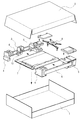
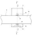
本発明の一実施形態による梱包構造について図面を参照して説明する。図1は液晶テレビジョン受像機の梱包構造を示す。梱包構造は、第1ケース1と、第2ケース2と、緩衝材3,4,5と、連結材6等によって構成されている。液晶テレビジョン受像機7は、画面を下向きに、横倒しに寝かされた姿勢でスタンド8と共に梱包される。
A packaging structure according to an embodiment of the present invention will be described with reference to the drawings. FIG. 1 shows a packaging structure of a liquid crystal television receiver. The packing structure includes a first case 1, a
第1ケース1は、緩衝材3,4,5及び連結材6が装着された液晶テレビジョン受像機7が載置されて、液晶テレビジョン受像機7の画面等を保護する。第2ケース2は、第1ケース1の上方から装着されて液晶テレビジョン受像機7の背面等を保護する。緩衝材3,4,5によって、第1ケース1及び第2ケース2の内部で液晶テレビジョン受像機7が支持される。緩衝材3は、液晶テレビジョン受像機7の上端縁の中央部に装着・当接される。緩衝材4,5は、液晶テレビジョン受像機7の上端縁の両端及び下端縁の両端、すなわち液晶テレビジョン受像機7の4隅に装着・当接される。連結材6は、緩衝材3,4,5を相互に連結する。図1においては、下端側の緩衝材3は省略されているが、必要に応じて追加してもよい。
In the first case 1, a liquid
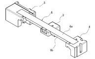
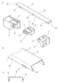
図2乃至図4は、緩衝材3,4,5及び連結材6を示す。連結材6は、弾性を有する板材、例えば紙製ダンボール、プラスチックダンボール等を断面がコの字状になるように折り曲げることによって形成され、天壁6aと2つの側壁6bからなる本体部と、折返し爪6cと係合爪6dを有する。折返し爪6cは、緩衝材3,4,5のそれぞれに2箇所ずつ対応するように6個設けられ、側壁6bの端縁の一部が鋭角に折り返されて形成されている。係合爪6dは、側壁6bの先端部の下端縁が連結材6の長手方向に延伸されて形成されている。
2 to 4 show the
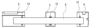
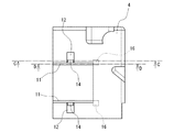
緩衝材3,4,5は、発泡ポリスチレン等の発泡材によって形成されている。緩衝材3,4,5は、スリット11と、指挿入凹部12とを有する。スリット11は、連結材6の側壁6bに対応して形成され、側壁6b及び折返し爪6cが差し込まれる。従って、スリット11の幅は、側壁6bの厚みと折返し爪6cの厚みを加えたものと略等しく設定されている。指挿入凹部12は、スリット11に連通し、開梱者の指を挿入可能に形成されている。スリット11及び指挿入凹部12は、液晶テレビジョン受像機7が当接される嵌挿孔13が形成されている側とは反対側の面に形成されている。
The
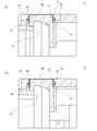
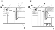
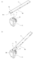
図5は、緩衝材3及び連結材6を拡大して示す。また、図6において(a)は、図5におけるA−A線断面、(b)は、図5におけるB−B線断面を示す。緩衝材3は、嵌挿孔13、爪収容部14及び段部15をさらに有する。嵌挿孔13は、図1に示すように、液晶テレビジョン受像機7の上端縁の中央部が嵌挿される。スリット11と、指挿入凹部12と、嵌挿孔13とは、それぞれ深さ方向が平行に形成されている。図5及び図6に示すように、爪収容部14は、その中央部分において指挿入凹部12と連通されている。また、図6に示すように、爪収容部14は、スリット11と連通し、スリット11から連結材6の折返し爪6cが弾性によって復元する方向に退避されて形成されている。段部15は、爪収容部14に落ち込んで収容された折返し爪6cの先端と係合するように、指挿入凹部12の(連結材6の長手方向の)両端において爪収容部14の上方に突出して形成されている。爪収容部14に落ち込んだ折返し爪6cの先端が段部15と係合することにより、緩衝材3と連結材6が強固に結合される。
FIG. 5 shows the
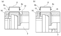
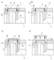
図7乃至図9は、緩衝材3に連結材6を装着する要領を示している。図7乃至図9において、(a)は、図5におけるA−A線断面、(b)は、図5におけるB−B線断面を示す。図7及び図8に示すように、連結材6は、その側壁6b及び折返し爪6cが緩衝材3のスリット11に挿入されることにより、緩衝材3に装着される。図8に示した状態では、折返し爪6cがスリット11の側壁によって側壁6bの方向に押圧されながら、スリット11を下方に進入する。さらに、図9に示した状態までスリット11が進入すると、爪収容部14に折返し爪6cの先端が落ち込んで収容され、折返し爪6cの先端と段部15が係合する。このとき、仮に連結材6を緩衝材3から引き抜こうとしても、折返し爪6cの先端と段部15が係合しているため、連結材6が緩衝材3から容易に引き抜かれることはない。
7 to 9 show a procedure for attaching the connecting
このように緩衝材3に装着された連結材6の折返し爪6cの中央部は、図5に示すように、指挿入凹部12から臨むことができる。そして、本実施形態の梱包構造においては、開梱時に作業者(開梱者)が、指挿入凹部12から指などを挿入して、折返し爪6cを側壁6bの方向に押圧することにより、折返し爪6cと段部15の係合を解いて容易に緩衝材3から連結材6を分離することができる。
As shown in FIG. 5, the central portion of the folded
図10は、開梱時において、連結材6から緩衝材3を分離する要領を示している。この図10において、(a)乃至(d)は、図5におけるA−A線断面を示す。開梱者は、(a)に示すように指Fなどを緩衝材3の指挿入凹部12に挿入し、(b)に示すように連結材6の折返し爪6cを側壁6bの方向に押圧する。これにより、折返し爪6cの先端と段部15との係合が解かれる。さらに開梱者は、(c)に示すように連結材6を上方に引き上げると、側壁6b及び折返し爪6cがスリット11の上方に移動し、(d)に示すように連結材6から緩衝材3を分離することができる。このとき、折返し爪6cを側壁6bの方向に押圧し続けることにより、折返し爪6cとスリット11との間に隙間が生じて、連結材6から緩衝材3を容易に分離することができる。
FIG. 10 shows a procedure for separating the
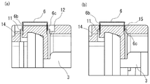
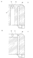
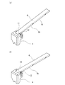
図11及び図12は、緩衝材4を示す。図12において、(a)は、図11におけるC−C線断面、(b)は、図11におけるD−D線断面を示す。緩衝材4は、スリット11、指挿入凹部12、嵌挿孔13、爪収容部14及び段部15の他、係合凹部16をさらに有する。スリット11、指挿入凹部12、嵌挿孔13、爪収容部14及び段部15の構成は、緩衝材3に形成されているものと同等である。係合凹部16は、スリット11に連通して係合爪6dに対応する形状に形成されている。なお、緩衝材5についても緩衝材4と同等の構成であるため、以下は緩衝材4についてのみ説明する。
11 and 12 show the
図13及び図14は、緩衝材4に連結材6を装着する要領を示している。図13において、(a)、(b)に示すように、まず、連結材6の係合爪6dを緩衝材4のスリット11に斜め方向に挿入し、連結材6を緩衝材4に押し込む。これにより、係合爪6dの先端が係合凹部16と係合することとなるが、この段階では、折返し爪6cは爪収容部14に落ち込んでいない。そして、図14において、(a)に示すように係合凹部16に係合している係合爪6dの先端を中心に連結材6を回動させると、(b)に示すように折返し爪6cは爪収容部14に落ち込んで収容され、折返し爪6cの先端と段部15が係合する。連結材6から緩衝材4を分離する際には、図13、図14に示した作業を逆に実行すればよい。すなわち、指挿入凹部12に指を挿入して折返し爪6cを連結材6の側壁6bの側に押圧することにより、折返し爪6cの先端と段部15との係合を解いた後、図14(a)の逆方向に連結材6を回動させ、図13(b)の逆方向に連結材6を引き抜けばよい。
13 and 14 show a procedure for mounting the connecting
以上のように、本実施形態の梱包構造によれば、開梱者が指挿入凹部12に指を挿入して折返し爪6cを連結材6の側壁6bの側に押圧することにより、折返し爪6cとスリット11との間に隙間を生じさせることができる。これにより、緩衝材3から連結材6を容易に分離することができる。
As described above, according to the packaging structure of the present embodiment, the unfolder inserts a finger into the
また、梱包時に連結材6の折返し爪6cが弾性によって復元すると、その先端が緩衝材3に形成された爪収容部14に落ち込んで段部15と係合するので、緩衝材3と連結材6を強固に結合させて、連結材6から緩衝材3が脱落することを防止することができる。なお、開梱時には、指挿入凹部12に指を挿入して折返し爪6cを連結材6の側壁6bの側に押圧することにより、折返し爪6cの先端と段部15との係合を解くことができるので、上記と同様に緩衝材3から連結材6を容易に分離することができる。
Further, when the folded
また、連結材6の長手方向の先端に形成された係合爪6dと、緩衝材4,5のスリット11に連通して形成された係合凹部16の係合によって、折返し爪6cの先端と段部15との係合と相まって、連結材6に対する緩衝材4,5の回転を防止することができる。これにより、緩衝材3対する上記効果に加えて、連結材6と緩衝材4,5とをより強固に結合させることができる。
Further, the
また、緩衝材3,4,5のスリット11及び指挿入凹部12は、被梱包物たる液晶テレビジョン受像機7が当接される側とは反対側の面に形成されているので、開梱時に液晶テレビジョン受像機7とは反対の側から連結材6を取外すことができる。これにより、緩衝材3から連結材6をより一層容易に分離できるようになる。
In addition, the
また、スリット11と、指挿入凹部12と、嵌挿孔13とは、それぞれ深さ方向が平行に形成されているので、緩衝材3,4,5を金型によって成形する場合、その金型構造を簡素にすることができ、ひいては緩衝材3,4,5の製造コストの低減を図ることができる。
Moreover, since the
また、液晶テレビジョン受像機7などの薄型で重量の大きな電子機器を被梱包物として適用する場合、被梱包物を寝かした姿勢で梱包することができるので、安定して作業を進めることができる。
In addition, when a thin and heavy electronic device such as the liquid
なお、本発明は上記実施形態の構成に限られることなく、少なくとも弾性を有する板材から成り、側壁6bの端縁の一部が折り返されて形成された折返し爪6cを有する連結材6と、連結材6の側壁6b、折返し爪6cが差し込まれるスリット11と、スリット11に連通し、開梱者の指を挿入可能な指挿入凹部12を有する緩衝材3を備えて構成されていればよい。また、本発明は種々の変形が可能であり、例えば、緩衝材3,4,5及び連結材6による構成は、特許文献1に示されるような薄型の被梱包物を起立姿勢で梱包する梱包構造にも広く適用することができる。
In addition, this invention is not restricted to the structure of the said embodiment, It consists of a board | plate material which has elasticity at least, The
1 第1ケース
2 第2ケース
3,4,5 緩衝材
6 連結材
6c 折返し爪
6d 係合爪
7 液晶テレビジョン受像機(被梱包物)
11 スリット
12 指挿入凹部
13 嵌挿孔
14 爪収容部
15 段部
16 係合凹部
DESCRIPTION OF SYMBOLS 1
DESCRIPTION OF
Claims (8)
前記連結材は、弾性を有する板材から成り、本体部と、該本体部の端縁の一部が折り返されて形成された折返し爪を有し、
前記緩衝材は、前記連結材の本体部の端縁及び折返し爪が差し込まれるスリットと、該スリットに連通し、開梱者の指を挿入可能な指挿入凹部を有することを特徴とする梱包構造。 In a packing structure provided with a plurality of cushioning materials that contact the packaged item and support the packaged item, and a connecting material that couples the plurality of cushioning materials,
The connecting material is made of a plate material having elasticity, and has a main body portion and a folded claw formed by folding a part of an end edge of the main body portion,
The cushioning material has a slit into which an end edge of the main body portion of the connecting material and the turn-back claw is inserted, and a finger insertion recess that communicates with the slit and into which an unpacker's finger can be inserted. .
前記連結材の長手方向の先端に結合される前記緩衝材には、前記スリットに連通して、前記係合爪に対応する係合凹部が形成されていることを特徴とする請求項1又は請求項2に記載の梱包構造。 An engaging claw is formed at the longitudinal end of the connecting material,
The engagement cushion corresponding to the engagement claw is formed in the buffer material coupled to the distal end in the longitudinal direction of the coupling material so as to communicate with the slit. Item 3. The packing structure according to Item 2.
前記被梱包物の一部が嵌挿される嵌挿孔と、前記端縁及び折返し爪が差し込まれるスリットと、該スリットに連通し開梱者の指を挿入可能な指挿入凹部を有することを特徴とする緩衝材。 In the cushioning material that is connected to the package by being connected to each other by the connecting material having the folded claw formed by folding a part of the edge,
It has a fitting insertion hole into which a part of the article to be packed is inserted, a slit into which the end edge and the folded claw are inserted, and a finger insertion recess that communicates with the slit and into which an unpacker's finger can be inserted. And cushioning material.
Priority Applications (1)
| Application Number | Priority Date | Filing Date | Title |
|---|---|---|---|
| JP2011005028A JP2012144284A (en) | 2011-01-13 | 2011-01-13 | Packaging structure, and cushioning material used for the same |
Applications Claiming Priority (1)
| Application Number | Priority Date | Filing Date | Title |
|---|---|---|---|
| JP2011005028A JP2012144284A (en) | 2011-01-13 | 2011-01-13 | Packaging structure, and cushioning material used for the same |
Publications (1)
| Publication Number | Publication Date |
|---|---|
| JP2012144284A true JP2012144284A (en) | 2012-08-02 |
Family
ID=46788297
Family Applications (1)
| Application Number | Title | Priority Date | Filing Date |
|---|---|---|---|
| JP2011005028A Withdrawn JP2012144284A (en) | 2011-01-13 | 2011-01-13 | Packaging structure, and cushioning material used for the same |
Country Status (1)
| Country | Link |
|---|---|
| JP (1) | JP2012144284A (en) |
-
2011
- 2011-01-13 JP JP2011005028A patent/JP2012144284A/en not_active Withdrawn
Similar Documents
| Publication | Publication Date | Title |
|---|---|---|
| JP4920747B2 (en) | Packing tool for goods transportation | |
| JP2006248549A (en) | Packing tool for goods transportation | |
| JP5955265B2 (en) | Packaging case and package | |
| JP2008222263A (en) | Packaging device | |
| JP6890961B2 (en) | Blanks and cartons | |
| JP3155097U (en) | Corner cushion | |
| KR200493805Y1 (en) | Packaging box | |
| JP5038287B2 (en) | Packaging container and package | |
| JP2006273357A (en) | Packing equipment | |
| JP2012144284A (en) | Packaging structure, and cushioning material used for the same | |
| JP3142537B2 (en) | Paper cushion | |
| JP3189377U (en) | Buffer article storage | |
| JP4962065B2 (en) | Packing material | |
| JP2002145338A (en) | Packaging pad and packaging device | |
| JP2008260559A (en) | Packing tool for goods transportation | |
| JP3162704U (en) | Packing container | |
| JP3286695B2 (en) | Buffer packaging material | |
| JP2015174688A (en) | Fixing member of object to be packed | |
| JP2018034883A (en) | Packing carton, television device, and packing method | |
| JP4578636B2 (en) | Cushion material | |
| JP3194333U (en) | Interior packaging | |
| JP5701586B2 (en) | Packing equipment | |
| JP3193598U (en) | Packing structure | |
| JP2018065582A (en) | Packaging material | |
| JP2013159369A (en) | Packing and packaging device for three-dimensional object |
Legal Events
| Date | Code | Title | Description |
|---|---|---|---|
| A300 | Withdrawal of application because of no request for examination |
Free format text: JAPANESE INTERMEDIATE CODE: A300 Effective date: 20140401 |