JP2018065582A - Packaging material - Google Patents
Packaging material Download PDFInfo
- Publication number
- JP2018065582A JP2018065582A JP2016204172A JP2016204172A JP2018065582A JP 2018065582 A JP2018065582 A JP 2018065582A JP 2016204172 A JP2016204172 A JP 2016204172A JP 2016204172 A JP2016204172 A JP 2016204172A JP 2018065582 A JP2018065582 A JP 2018065582A
- Authority
- JP
- Japan
- Prior art keywords
- packaging
- slope
- sandwiched
- product
- buffer
- Prior art date
- Legal status (The legal status is an assumption and is not a legal conclusion. Google has not performed a legal analysis and makes no representation as to the accuracy of the status listed.)
- Granted
Links
Images




Landscapes
- Details Of Rigid Or Semi-Rigid Containers (AREA)
- Pallets (AREA)
Abstract
【課題】廃棄時の作業性に優れ、かつ、被梱包物と外箱との間の収納部に被収納部材を安定して固定することが可能な包装部材を提供する。
【解決手段】包装部材1は、製品Pの側面を保護する多孔質の緩衝部材4と、製品Pおよび緩衝部材4を収納するトレイ付きパレット2および上ケース3と、製品Pおよび上ケース3の間の収納部Sに収納されるスロープ10を固定するためのシート部材からなる固定部材20と、を備える。固定部材20は、製品Pおよび緩衝部材4の間に挿入され、製品Pおよび緩衝部材4によって挟持される被挟持部22を有し、被挟持部22は、先端が被挟持部22の抜出方向側を向くように緩衝部材4側に折り曲げられた折り曲げ部22aを有する。
【選択図】図4Provided is a packaging member that is excellent in workability at the time of disposal and can stably fix a member to be stored in a storage part between a packaged item and an outer box.
A packaging member includes a porous cushioning member that protects a side surface of a product, a pallet with a tray that accommodates the product P and the cushioning member, and an upper case. And a fixing member 20 made of a sheet member for fixing the slope 10 stored in the storage portion S therebetween. The fixing member 20 is inserted between the product P and the buffer member 4, and has a sandwiched portion 22 that is sandwiched between the product P and the cushion member 4, and the sandwiched portion 22 has its tip extracted from the sandwiched portion 22. It has the bending part 22a bent by the buffer member 4 side so that it may face a direction side.
[Selection] Figure 4
Description
本発明は、包装部材に関し、特に、被梱包物の側面を保護する緩衝部材と、被梱包物および緩衝部材を収納する外箱と、を備え、被梱包物および外箱の間に被収納部材を収納する収納部が形成される包装部材に関するものである。 The present invention relates to a packaging member, and in particular, includes a shock-absorbing member that protects the side surface of the object to be packed, and an outer box that houses the object to be packed and the shock-absorbing member, and the member to be stored between the object to be packed and the outer box. It is related with the packaging member in which the accommodating part which accommodates is formed.
従来、電子機器等の重量のある製品(被梱包物)をトレイ付きパレットおよび上ケース等(包装部材)に梱包して輸送・保管する場合、トレイ付きパレットの製品設置面は床面に対して段差があるので、段差部分にスロープを形成し、キャスター付きの製品の場合はそのまま、キャスター付きでない場合、或いは梱包状態の場合はキャスター付きの台車に乗せてスロープ上を移動させる方法が一般的に用いられている。 Conventionally, when packaging and transporting heavy products (packaged items) such as electronic devices in pallets with trays and upper cases (packaging members), the product installation surface of the pallet with trays is against the floor surface. Since there is a step, it is common to form a slope at the step part and move it on the slope by placing it on a cart with casters in the case of a product with casters as it is, without casters or in a packed state It is used.
スロープ(被収納部材)は、製品と上ケース(外箱)との間のスペース(収納部)に収納され、製品と共に輸送・保管される。また、上ケースを取り外した状態でスロープが外側に倒れるのを防ぐために、スロープは、製品を保護する緩衝部材に例えばPP(ポリプロピレン)テープを用いて固定される。 The slope (member to be stored) is stored in a space (storage portion) between the product and the upper case (outer box), and is transported and stored together with the product. Further, in order to prevent the slope from falling outside with the upper case removed, the slope is fixed to a buffer member that protects the product using, for example, PP (polypropylene) tape.
なお、製品と上ケースとの間のスペースに被収納部材が収納される包装部材は、例えば特許文献1に開示されている。 A packaging member in which a member to be stored is stored in a space between a product and an upper case is disclosed in Patent Document 1, for example.
しかしながら、従来の包装部材のようにスロープを緩衝部材にPPテープ等を用いて固定する方法では、緩衝部材が多孔質(スポンジ状)からなる場合、PPテープの緩衝部材に対する接着性が低い(接着強度が不十分である)ため、スロープを安定して所定位置に固定することが困難であるという問題点があった。 However, in the method of fixing the slope to the buffer member using PP tape or the like as in the conventional packaging member, when the buffer member is made of a porous material (sponge), the adhesive property of the PP tape to the buffer member is low (adhesion) Therefore, there is a problem that it is difficult to stably fix the slope at a predetermined position.
なお、PPテープは段ボールに対する接着性が高いため、接着剤を用いて段ボール片を緩衝部材に接着し、スロープを段ボール片にPPテープを用いて固定する方法も考えられるが、廃棄時に段ボール片と緩衝部材とを分離するのが非常に困難である。 In addition, since PP tape has high adhesiveness to corrugated cardboard, a method of adhering the corrugated cardboard piece to the buffer member using an adhesive and fixing the slope to the corrugated cardboard piece using PP tape can be considered. It is very difficult to separate the buffer member.
本発明は、上記のような課題を解決するためになされたものであり、本発明の目的は、廃棄時の作業性に優れ、かつ、被梱包物と外箱との間の収納部に被収納部材を安定して固定することが可能な包装部材を提供することである。 The present invention has been made to solve the above-described problems, and an object of the present invention is to provide excellent workability at the time of disposal and cover the storage portion between the packaged item and the outer box. It is providing the packaging member which can fix a storage member stably.
上記目的を達成するために、本発明の第1の局面に係る包装部材は、被梱包物の側面を保護する多孔質の緩衝部材と、被梱包物および緩衝部材を収納する外箱と、被梱包物および外箱の間の収納部に収納される被収納部材を固定するためのシート部材からなる固定部材と、を備える。固定部材は、被梱包物および緩衝部材の間に挿入され、被梱包物および緩衝部材によって挟持される被挟持部を有し、被挟持部は、先端が被挟持部の抜出方向側を向くように緩衝部材側に折り曲げられた折り曲げ部を有する。 In order to achieve the above object, a packaging member according to a first aspect of the present invention includes a porous cushioning member that protects a side surface of an object to be packaged, an outer box that houses the object to be packaged and the cushioning member, And a fixing member made of a sheet member for fixing a member to be stored that is stored in a storage portion between the package and the outer box. The fixing member has a sandwiched portion that is inserted between the article to be packed and the buffer member and is sandwiched between the article to be packed and the cushion member, and the tip of the sandwiched part faces the extraction direction side of the sandwiched part. Thus, it has a bent part bent to the buffer member side.
本発明の第1の局面に係る包装部材によれば、被梱包物および外箱の間の収納部に収納される被収納部材を固定するためのシート部材からなる固定部材を備える。これにより、被収納部材を、PPテープ等によって接着性が低い多孔質の緩衝部材に固定する必要がなく、固定部材に固定することができる。 According to the packaging member which concerns on the 1st aspect of this invention, the fixing member which consists of a sheet | seat member for fixing the to-be-stored member accommodated in the accommodating part between a to-be-packaged item and an outer box is provided. Thereby, it is not necessary to fix a to-be-stored member to the porous buffer member with low adhesiveness with PP tape etc., and it can fix to a fixing member.
また、固定部材は、被梱包物および緩衝部材の間に挿入され、被梱包物および緩衝部材によって挟持される被挟持部を有し、被挟持部は、先端が被挟持部の抜出方向側を向くように緩衝部材側に折り曲げられた折り曲げ部を有する。これにより、折り曲げ部の先端が緩衝部材に引っ掛かりやすくなり、被挟持部が被梱包物と緩衝部材との間から抜け出るのを抑制することができる。 The fixing member has a sandwiched portion that is inserted between the article to be packed and the cushioning member and is sandwiched between the article to be packed and the cushioning member, and the sandwiched part has a tip that is on the side in the extraction direction of the sandwiched part. A bent portion that is bent toward the shock-absorbing member side. Thereby, the front-end | tip of a bending part becomes easy to be caught by a buffer member, and it can suppress that a to-be-clamped part slips out between a to-be-packaged item and a buffer member.
以上から、収納部に被収納部材を安定して固定することができる。 As described above, the member to be stored can be stably fixed to the storage unit.
また、固定部材の被挟持部を被梱包物および緩衝部材の間に挿入することにより固定部材を保持するので、接着剤を用いて固定部材を緩衝部材に固定する必要がない。これにより、廃棄時に固定部材と緩衝部材とを分離する必要がないので、固定部材および緩衝部材を容易に廃棄することができる。 Moreover, since the fixing member is held by inserting the sandwiched portion of the fixing member between the packaged item and the buffer member, there is no need to fix the fixing member to the buffer member using an adhesive. Thereby, since it is not necessary to isolate | separate a fixing member and a buffer member at the time of disposal, a fixing member and a buffer member can be discarded easily.
以下、本発明の実施形態について図面を参照して説明する。 Embodiments of the present invention will be described below with reference to the drawings.
図1〜図11を参照して、本発明の一実施形態の包装部材1について説明する。 With reference to FIGS. 1-11, the packaging member 1 of one Embodiment of this invention is demonstrated.
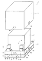
包装部材1は図1に示すように、トレイ付きパレット2と、製品(被梱包物)Pの側面及び上面を覆うとともに底面が開口した上ケース3と、トレイ付きパレット2上に配置され製品Pを外部衝撃から保護する多孔質(スポンジ状)の発泡ポリエチレン等からなる複数の緩衝部材4と、製品Pおよび上ケース3の間に形成される収納部Sに収納される2個のスロープ(被収納部材)10と、スロープ10を固定するための2個の固定部材20と、から構成されている。なお、トレイ付きパレット2および上ケース3によって、外箱が構成されている。
As shown in FIG. 1, the packaging member 1 is disposed on the
トレイ付きパレット2は図1および図2に示すように、製品Pが載置される底面5a及び底面5aの周縁に立設される4つのフラップ5bから成るトレイ5と、トレイ5の下面に固定されるパレット6とから成り、緩衝部材4は底面5aの四隅にフラップ5bとの間に所定の隙間を隔てて配置されている。この隙間には、上ケース3の下端部が挿入される。上ケース3の下端部には、フラップ5bの貫通穴8aと重なる位置に、貫通穴8bが形成されており、貫通穴8a、8bを重ねた状態で図示しない留め具を差し込むことにより、トレイ付きパレット2と上ケース3とを一体に連結する。トレイ付きパレット2は、包装部材1の底面を兼ねており、製品Pを梱包後、さらに包装部材1をパレット上に載せる必要がないため、特に大型の製品等の梱包及び運搬が容易になる。
As shown in FIGS. 1 and 2, the tray-equipped
パレット6は図1に示すように、例えば段ボールを折り曲げて形成した複数の支柱部6aと、各支柱部6aの上下面に固定される天板6b及び底板6cとから成り、各支柱部6aの間には、フォークリフトやハンドパレット(パレット運搬用台車)のアームを挿入するアーム挿入穴9が形成されている。天板6bは、トレイ5の底面5aに例えばかしめピン等(図示せず)を用いて固定されている。
As shown in FIG. 1, the
次に、スロープ10および固定部材20周辺の構造について説明する。
Next, the structure around the
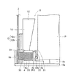
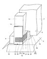
スロープ10は図3および図4に示すように、上ケース3と製品Pの側面との間に形成される収納部Sに折り畳んだ状態で収納される。固定部材20は図4および図5に示すように、緩衝部材4上に配置され、スロープ10は、接着テープ30を用いて固定部材20に固定される。なお、図3〜図5では、接着テープ30にハッチングを施している。
As shown in FIGS. 3 and 4, the
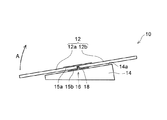
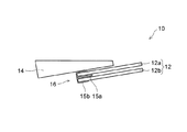
図6および図7に示すように、スロープ10は、折り畳み可能であって、2枚のパネル部材12a、12bから成るスロープ板12と、パネル部材12aの裏面に固定されたスロープ台14とから構成されている。なお、パネル部材12a、12bおよびスロープ台14は、木材、金属、硬質樹脂等によって形成されており、接着テープ30の接着性は良好である。
As shown in FIGS. 6 and 7, the
スロープ板12の表側及び裏側には、パネル部材12a、12bのヒンジ部16を跨ぐように可撓性のシート15a、15bが貼着されている。スロープ板12の上部を形成するパネル部材12bの上端付近には貫通穴(図示せず)が設けられている。この貫通穴(図示せず)は図5に示すように、結束バンド19によりスロープ10をトレイ付きパレット2の端部に連結するために用いられる。
図6および図7に示すように、スロープ板12の表面(谷折り側)に貼着されるシート15aは、ヒンジ部16を跨ぐように弛みなく接着されている。一方、スロープ板12の裏面(山折り側)に貼着されるシート15bには、ヒンジ部16を挟んで対峙するパネル部材12a、12bの間に弛み部分18が形成されている。この弛み部分18を伸長した長さは、パネル部材12a、12bの略2枚分の厚みとなっている。また、シート15bは、パネル部材12a、12bの裏面及び対向する端面、並びにスロープ台14の上面14aに接着されている。
As shown in FIGS. 6 and 7, the
図6の状態から、ヒンジ部16を支点としてパネル部材12aを時計回り方向(図6の矢印A方向)に回動させていくと、弛み部分18が直線状に伸長され、パネル部材12aがパネル部材12b上に重なり合うことによりスロープ板12が2つ折りとなる。このとき、パネル部材12aの裏面に固定されたスロープ台14もパネル部材12aと共に矢印A方向に回動することにより、図7に示すようにスロープ10が折り畳まれた状態となる。一方、図7の状態からパネル部材12aを反時計回りに回動させることにより、再びスロープ10が展張された図6の状態に戻すことができる。
When the
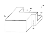
緩衝部材4は図5および図8に示すように、本体部4aと、製品Pの下方に配置される底面部4bと、製品Pの側面を保護する側面部4cおよび4dと、によって構成されている。製品Pは図4に示すように、トレイ付きパレット2の底面5aに設けられた台座部5c上に載置され、製品Pの下面と底面5aとの間には隙間が形成される。この隙間に緩衝部材4の底面部4bが挿入され、底面部4bは製品Pの下面から所定の隙間を隔てて配置される。
As shown in FIGS. 5 and 8, the
側面部4cおよび4dは、製品Pの側面に対向するように配置されるとともに、製品Pの側面から所定の隙間を隔てて配置される。また、側面部4cには図8に示すように、本体部4aから水平方向(製品Pの側面に対して平行)に突出する突出部4eが形成されている。
The
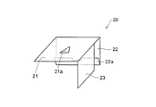
固定部材20は図9および図10に示すように、シート部材からなる部材(ここでは段ボール)を折り曲げることによって形成されており、矩形状の第1面21と、第1面21の一辺に対して略垂直に折り曲げられた被挟持部22と、第1面21の被挟持部22に隣接する一辺に対して略垂直に折り曲げられ、第1面21および被挟持部22の各々に対して略垂直な第2面23と、を有する。
As shown in FIGS. 9 and 10, the fixing
第1面21は図11に示すように、緩衝部材4の上面に配置される。第1面21の中央部には、作業者が固定部材20を取り扱う際に指先を引っ掛けるための開口部21aが形成されている。また、図4に示すように、第1面21上にスロープ10のスロープ台14が配置され、第1面21はスロープ台14と緩衝部材4とによって挟まれる。
As shown in FIG. 11, the
被挟持部22は、製品Pの側面と緩衝部材4の側面部4cとの間に挿入され、製品Pの側面と緩衝部材4の側面部4cとによって挟持される。被挟持部22は、先端が被挟持部22の抜出方向側(挿入方向とは反対側、第1面21側、上側)を向くように緩衝部材4側に折り曲げられた折り曲げ部22aを有する。折り曲げ部22aの先端は図10に示すように、切り欠き22bが形成されることによって凹凸形状に形成されている。図4に示すように、被挟持部22は、製品Pの側面と緩衝部材4の側面部4cとに当接し、折り曲げ部22aの先端は、緩衝部材4の側面部4cに引っ掛かる。
The sandwiched
第2面23は図11に示すように、本体部4aの側面に配置される。第2面23には図5に示すように、例えばPPテープからなる接着テープ(結合部材)30を用いてスロープ10が固定される。
The
また、第2面23は図9および図11に示すように、被挟持部22から所定距離を隔てて配置されており、第2面23と被挟持部22とによって緩衝部材4の突出部4eが挟まれる。これにより、スロープ10が製品Pから遠ざかる方向(外側、図4の反時計回り方向)に倒れる場合、第2面23の下端部が緩衝部材4の突出部4eに当接し、第2面23の回動が規制される。
Further, as shown in FIGS. 9 and 11, the
なお、図10の一点鎖線の位置を全て山折りすることによって図1の左側の固定部材20が形成され、一点鎖線の位置を全て谷折りすることによって図1の右側の固定部材20が形成される。
1 is formed by mountain-folding all the positions of the dashed-dotted line in FIG. 10, and the right-
次に、包装部材1を用いて製品Pを梱包および開梱する手順について説明する。 Next, a procedure for packing and unpacking the product P using the packaging member 1 will be described.
包装部材1によって製品Pを梱包する場合、スロープ10を用いて製品Pをトレイ付きパレット2の底面5a上の所定位置に配置するとともに、緩衝部材4を底面5aの四隅の所定位置に配置する。
When packing the product P with the packaging member 1, the product P is disposed at a predetermined position on the
そして、被挟持部22を製品Pの側面と緩衝部材4の側面部4cとの間に挿入しながら、固定部材20を緩衝部材4上に配置する。スロープ10を折り畳んだ状態で起立させ、接着テープ30を用いてスロープ10を固定部材20の第2面23に固定する。フラップ5bを起立させ、隣接するフラップ5b同士を接着テープ等(図示せず)で固定する。
Then, the fixing
その後、必要に応じて製品Pの上面、及び側面にも緩衝部材を配置した後、上ケース3を被せる。そして、フラップ5bの貫通穴8aと上ケース3の貫通穴8bとを重ねた状態で留め具(図示せず)を差し込むことにより、トレイ付きパレット2と上ケース3とを一体に連結する。
Then, after arranging a buffer member also on the upper surface and side surface of the product P as needed, the
一方、包装部材1を開梱する場合、留め具(図示せず)を取り外した後、上ケース3を取り外す。そして、接着テープ等(図示せず)を剥がしてフラップ5bを外側に傾倒させる。
On the other hand, when unpacking the packaging member 1, after removing a fastener (not shown), the
その後、接着テープ30をスロープ10および固定部材20から剥がした後、スロープ10を外側に傾倒させながらヒンジ部16を支点として展張することにより、トレイ付きパレット2から床面までの傾斜路が完成する。
Thereafter, the
そして、固定部材20および緩衝部材4を取り外すとともに、スロープ10を用いて製品Pをトレイ付きパレット2から床面に移動させる。
And while removing the fixing
本実施形態では、上記のように、収納部Sに収納されるスロープ10を固定するためのシート部材からなる固定部材20を備える。これにより、スロープ10を、PPテープ等によって接着性が低い多孔質の緩衝部材4に固定する必要がなく、固定部材20に固定することができる。
In this embodiment, the fixing
また、固定部材20の被挟持部22は、先端が被挟持部22の抜出方向側(上側)を向くように緩衝部材4側に折り曲げられた折り曲げ部22aを有する。これにより、折り曲げ部22aの先端が緩衝部材4に引っ掛かりやすくなり、被挟持部22が製品Pと緩衝部材4との間から抜け出るのを抑制することができる。
Further, the sandwiched
以上から、収納部Sにスロープ10を安定して固定することができる。
From the above, the
また、被挟持部22を製品Pと緩衝部材4との間に挿入することにより固定部材20を保持するので、接着剤を用いて固定部材20を緩衝部材4に固定する必要がない。これにより、廃棄時に固定部材20と緩衝部材4とを分離する必要がないので、固定部材20および緩衝部材4を容易に廃棄することができる。
Moreover, since the fixing
また、上記のように、折り曲げ部22aの先端は、凹凸形状に形成されている。これにより、折り曲げ部22aの先端が緩衝部材4により引っ掛かりやすくなるので、被挟持部22が製品Pと緩衝部材4との間から抜け出るのをより抑制することができる。
Further, as described above, the tip of the
また、上記のように、固定部材20は、第1面21と、被挟持部22と、第1面21に対して折り曲げられ、第1面21および被挟持部22の各々に対して略垂直な第2面23と、を有し、スロープ10は接着テープ30を用いて第2面23に固定される。これにより、スロープ10を容易に固定部材20に固定することができる。
Further, as described above, the fixing
また、上記のように、被挟持部22および第2面23は、緩衝部材4の突出部4eを挟み込むように配置されている。これにより、スロープ10が製品Pから遠ざかる方向に倒れようとする際に、第2面23の下端部が緩衝部材4に当接する。このため、被挟持部22が製品Pと緩衝部材4との間から抜け出るのをより抑制することができるとともに、スロープ10が倒れるのをより抑制することができる。
Further, as described above, the sandwiched
また、上記のように、トレイ付きパレット2と上ケース3とを含む包装部材1は大型であり、スロープ10も大型で重量物になるため、スロープ10を安定して固定する必要性が高い。このため、トレイ付きパレット2と上ケース3とを含む包装部材1に本発明を適用することは特に効果的である。
In addition, as described above, the packaging member 1 including the tray-equipped
なお、今回開示された実施形態は、すべての点で例示であって制限的なものではないと考えられるべきである。本発明の範囲は、上記した実施形態の説明ではなく特許請求の範囲によって示され、さらに特許請求の範囲と均等の意味および範囲内でのすべての変更が含まれる。 The embodiment disclosed this time should be considered as illustrative in all points and not restrictive. The scope of the present invention is shown not by the above description of the embodiments but by the scope of claims for patent, and further includes all modifications within the meaning and scope equivalent to the scope of claims for patent.
例えば、上記実施形態では、被収納部材(スロープ10)が包装部材1に連結されている例について示したが、本発明はこれに限らず、被収納部材は包装部材に連結されていなくてもよい。 For example, in the said embodiment, although the example to which the to-be-stored member (slope 10) was connected with the packaging member 1 was shown, this invention is not restricted to this, Even if the to-be-stored member is not connected with the packaging member, Good.
また、上記実施形態では、被収納部材がスロープ10である例について示したが、本発明はこれに限らない。例えば、被収納部材は製品Pの付属品であってもよい。
Moreover, in the said embodiment, although the example to which the to-be-stored member was the
また、上記実施形態では、固定部材20が段ボールによって形成されている例について示したが、本発明はこれに限らない。例えば、固定部材20は樹脂シートによって形成されていてもよい。
Moreover, in the said embodiment, although the example which the fixing
また、上記実施形態では、包装部材1がパレット5を含む例について示したが、本発明はこれに限らず、包装部材はパレットを含んでいなくてもよい。
Moreover, although the packaging member 1 showed about the example containing the
また、上記実施形態では、固定部材20の折り曲げ部22aの先端に1つの切り欠き22bを形成した例について示したが、本発明はこれに限らない。固定部材20の折り曲げ部22aの先端に複数の切り欠きを形成してもよい。また、例えば図12に示した本発明の第1変形例の固定部材20のように、固定部材20の折り曲げ部22aの先端を鋸刃形状に形成してもよい。このように構成すれば、折り曲げ部22aの先端が緩衝部材4にさらに引っ掛かりやすくなるので、被挟持部22が製品Pと緩衝部材4との間から抜け出るのをさらに抑制することができる。
Moreover, although the example which formed one
また、上記実施形態では、固定部材20の被挟持部22を1回だけ折り曲げて折り曲げ部22aを形成する例について示したが、本発明はこれに限らない。例えば図13に示した本発明の第2変形例の固定部材20のように、被挟持部22を複数回(奇数回)折り曲げて折り曲げ部22aを形成してもよい。このように構成すれば、折り曲げ部22aの先端の緩衝部材4に対する圧接力が高くなり、折り曲げ部22aの先端が緩衝部材4にさらに引っ掛かりやすくなるので、被挟持部22が製品Pと緩衝部材4との間から抜け出るのをさらに抑制することができる。
Moreover, although the said embodiment showed about the example which bends the to-
また、上述した実施形態および変形例の構成を適宜組み合わせて得られる構成についても、本発明の技術的範囲に含まれる。 Further, a configuration obtained by appropriately combining the configurations of the above-described embodiment and modification examples is also included in the technical scope of the present invention.
1 包装部材
2 トレイ付きパレット(外箱)
3 上ケース(外箱)
4 緩衝部材
5 トレイ
10 スロープ(被収納部材)
20 固定部材
21 第1面
22 被挟持部
22a 折り曲げ部
23 第2面
30 接着テープ(結合部材)
P 製品(被梱包物)
S 収納部
1
3 Upper case (outer box)
4 cushioning
DESCRIPTION OF
P product (packaged items)
S storage
Claims (9)
前記被梱包物および前記緩衝部材を収納する外箱と、
前記被梱包物および前記外箱の間の収納部に収納される被収納部材を固定するためのシート部材からなる固定部材と、
を備え、
前記固定部材は、前記被梱包物および前記緩衝部材の間に挿入され、前記被梱包物および前記緩衝部材によって挟持される被挟持部を有し、
前記被挟持部は、先端が前記被挟持部の抜出方向側を向くように前記緩衝部材側に折り曲げられた折り曲げ部を有することを特徴とする包装部材。 A porous cushioning member for protecting the side surface of the packaged item;
An outer box for storing the article to be packed and the buffer member;
A fixing member composed of a sheet member for fixing a member to be stored that is stored in a storage portion between the item to be packed and the outer box;
With
The fixing member is inserted between the article to be packed and the cushioning member, and has a sandwiched portion that is sandwiched between the article to be packed and the cushioning member,
The packaging member, wherein the sandwiched portion has a bent portion that is folded toward the buffer member so that a tip thereof faces a pulling-out direction side of the sandwiched portion.
前記被収納部材は結合部材を用いて前記第2面に固定されることを特徴とする請求項1〜3のいずれか1項に記載の包装部材。 The fixing member is bent with respect to the first surface, the first surface contacting the upper surface of the buffer member, the sandwiched portion bent substantially perpendicular to the first surface, and the first surface. A second surface substantially perpendicular to each of the surface and the sandwiched portion,
The packaging member according to claim 1, wherein the member to be stored is fixed to the second surface using a coupling member.
Priority Applications (1)
| Application Number | Priority Date | Filing Date | Title |
|---|---|---|---|
| JP2016204172A JP6673136B2 (en) | 2016-10-18 | 2016-10-18 | Packaging materials |
Applications Claiming Priority (1)
| Application Number | Priority Date | Filing Date | Title |
|---|---|---|---|
| JP2016204172A JP6673136B2 (en) | 2016-10-18 | 2016-10-18 | Packaging materials |
Publications (2)
| Publication Number | Publication Date |
|---|---|
| JP2018065582A true JP2018065582A (en) | 2018-04-26 |
| JP6673136B2 JP6673136B2 (en) | 2020-03-25 |
Family
ID=62085679
Family Applications (1)
| Application Number | Title | Priority Date | Filing Date |
|---|---|---|---|
| JP2016204172A Active JP6673136B2 (en) | 2016-10-18 | 2016-10-18 | Packaging materials |
Country Status (1)
| Country | Link |
|---|---|
| JP (1) | JP6673136B2 (en) |
Cited By (2)
| Publication number | Priority date | Publication date | Assignee | Title |
|---|---|---|---|---|
| CN110371367A (en) * | 2019-07-29 | 2019-10-25 | 杜秀玲 | A kind of transport mechanism of the autoloader for plastic tableware packaging |
| CN119176335A (en) * | 2023-06-21 | 2024-12-24 | 京瓷办公信息系统株式会社 | Packaging component |
Citations (9)
| Publication number | Priority date | Publication date | Assignee | Title |
|---|---|---|---|---|
| JPS6470387A (en) * | 1987-09-10 | 1989-03-15 | Ricoh Kk | Package with lifter |
| JPH10114332A (en) * | 1996-10-03 | 1998-05-06 | Shinwa Corp:Kk | Packing transport container |
| JPH10203531A (en) * | 1997-01-20 | 1998-08-04 | Gifu Plast Ind Co Ltd | Plastic pallets |
| JP3062252U (en) * | 1998-12-15 | 1999-09-28 | 株式会社ケイアンドジィ | Locking stopper |
| JP2001122265A (en) * | 1999-10-22 | 2001-05-08 | Asahi:Kk | Load collapse prevention device |
| US20070151883A1 (en) * | 2006-01-04 | 2007-07-05 | Smith Russell L | Preservation skid |
| JP2007246155A (en) * | 2006-03-20 | 2007-09-27 | Kyocera Mita Corp | Packing case |
| JP2010208672A (en) * | 2009-03-11 | 2010-09-24 | Orion Mach Co Ltd | Corrugated board packaging box |
| JP2015081098A (en) * | 2013-10-21 | 2015-04-27 | 京セラドキュメントソリューションズ株式会社 | Package cushioning member and packaging material including the same |
-
2016
- 2016-10-18 JP JP2016204172A patent/JP6673136B2/en active Active
Patent Citations (9)
| Publication number | Priority date | Publication date | Assignee | Title |
|---|---|---|---|---|
| JPS6470387A (en) * | 1987-09-10 | 1989-03-15 | Ricoh Kk | Package with lifter |
| JPH10114332A (en) * | 1996-10-03 | 1998-05-06 | Shinwa Corp:Kk | Packing transport container |
| JPH10203531A (en) * | 1997-01-20 | 1998-08-04 | Gifu Plast Ind Co Ltd | Plastic pallets |
| JP3062252U (en) * | 1998-12-15 | 1999-09-28 | 株式会社ケイアンドジィ | Locking stopper |
| JP2001122265A (en) * | 1999-10-22 | 2001-05-08 | Asahi:Kk | Load collapse prevention device |
| US20070151883A1 (en) * | 2006-01-04 | 2007-07-05 | Smith Russell L | Preservation skid |
| JP2007246155A (en) * | 2006-03-20 | 2007-09-27 | Kyocera Mita Corp | Packing case |
| JP2010208672A (en) * | 2009-03-11 | 2010-09-24 | Orion Mach Co Ltd | Corrugated board packaging box |
| JP2015081098A (en) * | 2013-10-21 | 2015-04-27 | 京セラドキュメントソリューションズ株式会社 | Package cushioning member and packaging material including the same |
Cited By (2)
| Publication number | Priority date | Publication date | Assignee | Title |
|---|---|---|---|---|
| CN110371367A (en) * | 2019-07-29 | 2019-10-25 | 杜秀玲 | A kind of transport mechanism of the autoloader for plastic tableware packaging |
| CN119176335A (en) * | 2023-06-21 | 2024-12-24 | 京瓷办公信息系统株式会社 | Packaging component |
Also Published As
| Publication number | Publication date |
|---|---|
| JP6673136B2 (en) | 2020-03-25 |
Similar Documents
| Publication | Publication Date | Title |
|---|---|---|
| JP5707838B2 (en) | Packing box | |
| JP2014009020A (en) | Packaging material and packaging body | |
| US10370169B2 (en) | Packing device | |
| JP5240251B2 (en) | Packing material | |
| JP4296567B2 (en) | Package for transportation of goods | |
| JP6456640B2 (en) | Goods transport packaging | |
| JP6673136B2 (en) | Packaging materials | |
| JP2011016549A (en) | Returnable box | |
| US8141771B2 (en) | Packaging carton box structure | |
| JP2017057016A (en) | Packaging material and package | |
| JP4603871B2 (en) | Small information equipment delivery container | |
| JP6264564B2 (en) | Packaging box | |
| JP2021041964A (en) | Packing material and packaging material with it | |
| JP2010208672A (en) | Corrugated board packaging box | |
| CN101214870B (en) | Carrying device and packaging device for plate-shaped electronic device | |
| JP2005289490A (en) | Corrugated cardboard packing device | |
| JP6245962B2 (en) | Returnable packaging material | |
| JP2013252868A (en) | Packaging box | |
| JP5629806B2 (en) | Packing material | |
| JP4507828B2 (en) | Parts protection support device | |
| JP5426042B1 (en) | Packaging for electronic equipment | |
| JP2009107720A (en) | Packing equipment | |
| JP2010013180A (en) | Simplified corrugated cardboard package box | |
| JP2007069938A (en) | Packing box | |
| JP3146554U (en) | Shock relief transport container |
Legal Events
| Date | Code | Title | Description |
|---|---|---|---|
| A621 | Written request for application examination |
Free format text: JAPANESE INTERMEDIATE CODE: A621 Effective date: 20180829 |
|
| A977 | Report on retrieval |
Free format text: JAPANESE INTERMEDIATE CODE: A971007 Effective date: 20190621 |
|
| A131 | Notification of reasons for refusal |
Free format text: JAPANESE INTERMEDIATE CODE: A131 Effective date: 20190702 |
|
| A521 | Request for written amendment filed |
Free format text: JAPANESE INTERMEDIATE CODE: A523 Effective date: 20190829 |
|
| A131 | Notification of reasons for refusal |
Free format text: JAPANESE INTERMEDIATE CODE: A131 Effective date: 20191203 |
|
| A521 | Request for written amendment filed |
Free format text: JAPANESE INTERMEDIATE CODE: A523 Effective date: 20200121 |
|
| TRDD | Decision of grant or rejection written | ||
| A01 | Written decision to grant a patent or to grant a registration (utility model) |
Free format text: JAPANESE INTERMEDIATE CODE: A01 Effective date: 20200204 |
|
| A61 | First payment of annual fees (during grant procedure) |
Free format text: JAPANESE INTERMEDIATE CODE: A61 Effective date: 20200217 |
|
| R150 | Certificate of patent or registration of utility model |
Ref document number: 6673136 Country of ref document: JP Free format text: JAPANESE INTERMEDIATE CODE: R150 |