JP2012144263A - Conveyance box and conveyance system - Google Patents

Conveyance box and conveyance system Download PDF

Info

Publication number
JP2012144263A
JP2012144263A JP2011002395A JP2011002395A JP2012144263A JP 2012144263 A JP2012144263 A JP 2012144263A JP 2011002395 A JP2011002395 A JP 2011002395A JP 2011002395 A JP2011002395 A JP 2011002395A JP 2012144263 A JP2012144263 A JP 2012144263A
Authority
JP
Japan
Prior art keywords
storage chamber
chamber
workpiece
transport box
volume
Prior art date
Legal status (The legal status is an assumption and is not a legal conclusion. Google has not performed a legal analysis and makes no representation as to the accuracy of the status listed.)
Withdrawn
Application number
JP2011002395A
Other languages
Japanese (ja)
Inventor
Hiroaki Fujii
博章 藤井
Current Assignee (The listed assignees may be inaccurate. Google has not performed a legal analysis and makes no representation or warranty as to the accuracy of the list.)
Olympus Corp
Original Assignee
Olympus Corp
Priority date (The priority date is an assumption and is not a legal conclusion. Google has not performed a legal analysis and makes no representation as to the accuracy of the date listed.)
Filing date
Publication date
Application filed by Olympus Corp filed Critical Olympus Corp
Priority to JP2011002395A priority Critical patent/JP2012144263A/en
Publication of JP2012144263A publication Critical patent/JP2012144263A/en
Withdrawn legal-status Critical Current

Links

Images

Landscapes

  • Packaging Frangible Articles (AREA)

Abstract

PROBLEM TO BE SOLVED: To provide a conveyance box and a conveyance system which can convey a workpiece while suppressing the fluctuation of an atmosphere in a chamber, and has a simple structure.SOLUTION: The conveyance box 1 used to convey the workpiece W from a first processing system 220 to a second processing system 230 in two or more processing systems 200 that process the workpiece W includes an accommodation chamber 4 that accommodates the workpiece W internally, a volume adjusting mechanism that changes the volume of the accommodation chamber 4, and a sealing means 11 that seals the accommodation chamber 4 openably and airtightly.

Description

本発明は、ワークを搬送する搬送ボックスおよび搬送システムに関する。   The present invention relates to a transport box and a transport system for transporting a workpiece.

従来、ワークに対して加工や検査などの処理を行う場合に、処理に適した雰囲気となるように調整されたチャンバーを有する処理システムを用いて処理を行うことが知られている。また、互いに異なる複数の処理をワークに対して行う場合に、ある雰囲気の下で処理を行う処理システムから別の雰囲気の下で他の処理を行う処理システムへワークを移す場合がある。   Conventionally, when processing such as processing or inspection is performed on a workpiece, it is known to perform processing using a processing system having a chamber adjusted to have an atmosphere suitable for processing. When a plurality of different processes are performed on a workpiece, the workpiece may be transferred from a processing system that performs processing in a certain atmosphere to a processing system that performs other processing in another atmosphere.

複数の処理システムの各チャンバー間でワークを搬送する場合には、手作業により、あるいはワークの搬送装置を用いてワークを搬送する。複数のチャンバー間でワークを搬送する搬送装置の例として、例えば特許文献1にはワーク(物品)の搬入搬出装置が記載されている。特許文献1に記載の搬入搬出装置は、所定の雰囲気条件に保持されたチャンバーと、チャンバーに対してワークを搬入あるいは搬出する搬送装置とを備えている。特許文献1に記載の搬送装置は、ワークを保持する保持室と、保持室内の雰囲気条件を制御する制御系とを有している。
特許文献1に記載の搬入搬出装置によれば、搬送装置に設けられた制御系により、搬送装置の保持室内の雰囲気条件をチャンバーの雰囲気条件に適合させることができる。これにより、特許文献1に記載の搬入搬出装置は、チャンバー内の雰囲気の変動を抑えることができる。
When a workpiece is transferred between chambers of a plurality of processing systems, the workpiece is transferred manually or using a workpiece transfer device. As an example of a conveying device that conveys a workpiece between a plurality of chambers, for example, Patent Document 1 describes a workpiece (article) loading / unloading device. The carry-in / carry-out device described in Patent Document 1 includes a chamber that is maintained at a predetermined atmospheric condition and a transfer device that carries a workpiece into or out of the chamber. The transfer device described in Patent Literature 1 includes a holding chamber that holds a workpiece and a control system that controls atmospheric conditions in the holding chamber.
According to the carry-in / out device described in Patent Literature 1, the atmospheric condition in the holding chamber of the conveyance device can be adapted to the atmospheric condition of the chamber by the control system provided in the conveyance device. Thereby, the carrying-in / out apparatus of patent document 1 can suppress the fluctuation | variation of the atmosphere in a chamber.

特開平5−335402号公報JP-A-5-335402

しかしながら、特許文献1に記載の搬入搬出装置では、チャンバーに対してワークを搬入したり搬出したりするたびに、制御系によって保持室内の雰囲気を調整しなければならない。このため、特許文献1に記載の搬入搬出装置では、搬送装置の構成が複雑であるとともに雰囲気の調整のために余計な時間を要するという問題があった。
また、特許文献1に記載の搬送装置を用いて互いに雰囲気条件が異なるチャンバー間でワークを搬送しようとすると、保持室内の気体を置換する必要がある。しかしながら、特許文献1に記載の搬送装置では、保持室内の不要な気体を大気開放した場合には大気開放されたガスを再利用することは困難であり、保持室内の不要な気体を別途タンクなどに回収しようとすると構成が複雑となる。
However, in the carry-in / carry-out apparatus described in Patent Document 1, the atmosphere in the holding chamber must be adjusted by the control system every time a workpiece is carried in or out of the chamber. For this reason, in the carrying-in / out apparatus described in Patent Document 1, there is a problem that the configuration of the conveying apparatus is complicated and extra time is required for adjusting the atmosphere.
Further, when the workpiece is transferred between chambers having different atmospheric conditions using the transfer device described in Patent Document 1, it is necessary to replace the gas in the holding chamber. However, in the transfer device described in Patent Document 1, when unnecessary gas in the holding chamber is released to the atmosphere, it is difficult to reuse the gas released to the atmosphere. If you try to collect it, the configuration becomes complicated.

本発明は、上述した事情に鑑みてなされたものであって、その目的は、ワークの受け渡しを行うチャンバー内の雰囲気の変動を抑えつつワークを搬送可能であって構成が簡素な搬送ボックスおよび搬送システムを提供することである。   The present invention has been made in view of the above-described circumstances, and an object of the present invention is to provide a transport box and a transport structure that can transport a workpiece while suppressing a change in atmosphere in a chamber for delivering the workpiece, and has a simple configuration. Is to provide a system.

上記課題を解決するために、この発明は以下の手段を提案している。
本発明の搬送ボックスは、ワークに対して処理を行う複数の処理システムにおける第1処理システムから第2処理システムへ前記ワークを搬送するために使用される搬送ボックスであって、前記ワークを内部に収容する収容室と、前記収容室の容積を変化させる容積調整機構と、前記収容室を開閉可能且つ気密に封止する封止手段と、を備えることを特徴とする搬送ボックスである。
In order to solve the above problems, the present invention proposes the following means.
The transport box of the present invention is a transport box used for transporting the work from the first processing system to the second processing system in a plurality of processing systems that perform processing on the work, and the work is placed inside. A transport box comprising: a storage chamber for storing; a volume adjusting mechanism for changing a volume of the storage chamber; and a sealing unit for opening and closing the storage chamber in an airtight manner.

また、前記ワークを格納する格納部が形成されたトレーをさらに備え、前記容積調整機構は、前記ワークが格納された前記トレーが前記収容室内へ収容される動作によって、当該トレーを収容する前における前記収容室の初期容積から、当該トレーが前記収容室内で占有する包絡体積を前記初期容積に足した収容後容積まで、前記収容室の容積を漸次増加させることが好ましい。   In addition, the apparatus further includes a tray in which a storage unit for storing the workpiece is formed, and the volume adjustment mechanism is configured to store the tray in the storage chamber before the tray is stored in the storage chamber. It is preferable that the volume of the storage chamber is gradually increased from the initial volume of the storage chamber to a post-storage volume obtained by adding the envelope volume occupied by the tray in the storage chamber to the initial volume.

また、前記収容室は、前記トレーの外面に対して摺動可能に接する内寸の筒状に形成されており、前記容積調整機構は、前記収容室の内周面に対して前記収容室の中心軸線方向へ移動可能であって前記ワークが載置される載置台と、前記載置台を前記中心軸線方向へ移動させる台移動手段と、を備えることが好ましい。   Further, the storage chamber is formed in a cylindrical shape having an inner size that is slidably in contact with the outer surface of the tray, and the volume adjusting mechanism is configured so that the volume of the storage chamber is relative to the inner peripheral surface of the storage chamber. It is preferable to include a mounting table that is movable in the central axis direction and on which the workpiece is mounted, and a table moving unit that moves the mounting table in the central axis direction.

また、前記台移動手段は、前記収容室内へ前記ワークを収容するときの前記ワークの移動方向とは反対方向へ前記載置台を付勢する付勢部材を有することが好ましい。   Moreover, it is preferable that the said base movement means has a urging member which urges | biases the said mounting base to the opposite direction to the moving direction of the said workpiece | work when accommodating the said workpiece | work in the said storage chamber.

また、前記収容室は、前記ワークを受入れる開口が形成され、前記開口には、前記開口から前記収容室の外側方向へ前記ワークを移動させる前記付勢部材の付勢力に抗するストッパが設けられていることが好ましい。   The storage chamber has an opening for receiving the workpiece, and the opening is provided with a stopper that resists the biasing force of the biasing member that moves the workpiece from the opening toward the outside of the storage chamber. It is preferable.

また、前記収容室内の圧力を調整する圧力調整機構をさらに備えていてもよい。
また、前記圧力調整機構は、前記収容室の容積を前記容積調整機構とは独立して変化させることが好ましい。
また、前記圧力調整機構は、前記収容室の内部と連通された圧力調整室と、前記圧力調整室の容積を変化させる容積変更手段と、を備えていることが好ましい。
また、前記圧力調整室は前記載置台に形成されていることが好ましい。
Moreover, you may further provide the pressure adjustment mechanism which adjusts the pressure in the said storage chamber.
Moreover, it is preferable that the said pressure adjustment mechanism changes the volume of the said storage chamber independently of the said volume adjustment mechanism.
In addition, it is preferable that the pressure adjustment mechanism includes a pressure adjustment chamber that communicates with the inside of the storage chamber, and a volume changing unit that changes the volume of the pressure adjustment chamber.
Moreover, it is preferable that the said pressure regulation chamber is formed in the said mounting stand.

本発明の搬送システムは、本発明の搬送ボックスと、前記第1処理システムから前記第2処理システムへ前記搬送ボックスを搬送する搬送装置と、を備えることを特徴とする搬送システムである。   The transport system of the present invention is a transport system comprising the transport box of the present invention and a transport device that transports the transport box from the first processing system to the second processing system.

本発明の搬送ボックスおよび搬送システムによれば、チャンバー内の雰囲気の変動を抑えつつワークを搬送可能であり、且つ構成を簡素とすることができる。   According to the transfer box and the transfer system of the present invention, the workpiece can be transferred while suppressing the change in the atmosphere in the chamber, and the configuration can be simplified.

本発明の第1実施形態の搬送ボックスおよび搬送システムと同実施形態の処理システムとを示す模式図である。It is a schematic diagram which shows the conveyance box and conveyance system of 1st Embodiment of this invention, and the processing system of the same embodiment. 搬送システムとともに使用される処理システムの一部の構成を示す部分断面図である。It is a fragmentary sectional view which shows the structure of a part of processing system used with a conveyance system. 搬送システムとともに使用される他の処理システムの一部の構成を示す部分断面図である。It is a fragmentary sectional view which shows the structure of a part of other processing system used with a conveyance system. 同搬送ボックスを示す部分断面図である。It is a fragmentary sectional view showing the conveyance box. 同搬送ボックス内に複数のワークが収容された状態を示す部分断面図である。It is a fragmentary sectional view which shows the state in which the several workpiece | work was accommodated in the conveyance box. 図2の一部を拡大して示す拡大図である。It is an enlarged view which expands and shows a part of FIG. 図4の一部を拡大して示す拡大図である。It is an enlarged view which expands and shows a part of FIG. 同搬送ボックスの使用時における処理システムの動作を説明するための図である。It is a figure for demonstrating operation | movement of the processing system at the time of use of the conveyance box. 同搬送ボックスの使用時における処理システムの動作を説明するための図である。It is a figure for demonstrating operation | movement of the processing system at the time of use of the conveyance box. 同搬送ボックスの使用時における同搬送ボックスおよび同処理システムの動作を説明するための図である。It is a figure for demonstrating operation | movement of the conveyance box and the processing system at the time of use of the conveyance box. 本発明の第2実施形態の搬送ボックスを示す部分断面図である。It is a fragmentary sectional view which shows the conveyance box of 2nd Embodiment of this invention. 同搬送ボックスを示す部分断面図である。It is a fragmentary sectional view showing the conveyance box. 同実施形態の変形例の搬送ボックスの構成を示す部分断面図である。It is a fragmentary sectional view showing the composition of the conveyance box of the modification of the embodiment. (a)および(b)は、本発明の搬送ボックスの他の構成例を示す部分断面図である。(A) And (b) is a fragmentary sectional view which shows the other structural example of the conveyance box of this invention. (a)および(b)は、本発明の搬送ボックスのさらに他の構成例を示す部分断面図である。(A) And (b) is a fragmentary sectional view which shows the further another structural example of the conveyance box of this invention.

(第1実施形態)
本発明の第1実施形態の搬送ボックス1および搬送システム100について、搬送ボックス1を備える搬送システム100の例で説明する。
図1は、本実施形態の搬送ボックス1および搬送システム100と、本実施形態の処理システム200とを示す模式図である。
図1に示すように、搬送システム100は、ワークWに対して処理を行う処理システム200とともに使用されるシステムであり、処理システム200において処理されるワークWを搬送するためのシステムである。
本実施形態において、処理システム200における処理とは、レンズやミラーなどの光学素子の成形、形状測定、および洗浄であり、処理システム200におけるワークWとはガラス材料や樹脂材料によって形成されたワークである。
(First embodiment)
The conveyance box 1 and the conveyance system 100 of 1st Embodiment of this invention are demonstrated in the example of the conveyance system 100 provided with the conveyance box 1. FIG.
FIG. 1 is a schematic diagram illustrating a transport box 1 and a transport system 100 according to the present embodiment, and a processing system 200 according to the present embodiment.
As shown in FIG. 1, the transport system 100 is a system that is used together with a processing system 200 that performs processing on the workpiece W, and is a system for transporting the workpiece W processed in the processing system 200.
In the present embodiment, the processing in the processing system 200 is molding, shape measurement, and cleaning of optical elements such as lenses and mirrors, and the workpiece W in the processing system 200 is a workpiece formed of a glass material or a resin material. is there.

処理システム200は、素材(ワークW)を供給する素材供給機210と、素材供給機210によって供給されるワークWを所定の形状に成形する成形機220(第1処理システム)と、成形機220によって成形された成形品(ワークW)の形状を測定する測定機230(第2処理システム)と、測定機230によって形状が測定されたワークWを洗浄する洗浄機240(第3処理システム)とを備え、搬送システム100とともに使用されるシステムである。   The processing system 200 includes a material supply machine 210 that supplies a material (work W), a molding machine 220 (first processing system) that forms the work W supplied by the material supply machine 210 into a predetermined shape, and a molding machine 220. A measuring machine 230 (second processing system) for measuring the shape of the molded product (work W) formed by the above, and a cleaning machine 240 (third processing system) for cleaning the work W whose shape has been measured by the measuring machine 230. It is a system used with the conveyance system 100.

素材供給機210、成形機220、測定機230、および洗浄機240は、それぞれ雰囲気が異なるチャンバー構造となっており、処理に応じた温度、圧力、ガスの種類および濃度、並びにクリーン度が設定されている。   The material supply machine 210, the molding machine 220, the measuring machine 230, and the washing machine 240 have chamber structures with different atmospheres, and the temperature, pressure, gas type and concentration, and cleanliness are set according to processing. ing.

素材供給機210には、素材供給機210からワークWを排出するための排出口211が設けられている。   The material feeder 210 is provided with a discharge port 211 for discharging the workpiece W from the material feeder 210.

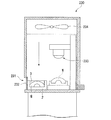
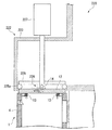
図2は、成形機220の一部の構成を示す部分断面図である。図6は図2において符号Xで示す部分を拡大して示す拡大図である。
図1に示すように、成形機220には、素材供給機210から排出されたワークWが投入される投入口221および成形後のワークWが排出される排出口222が設けられている。
図2および図6に示すように、成形機220の排出口222は、成形機220のチャンバーと連通されたカバー223と、カバー223に設けられた開閉部224とを有する。
FIG. 2 is a partial cross-sectional view showing a partial configuration of the molding machine 220. FIG. 6 is an enlarged view showing a portion indicated by a symbol X in FIG.
As shown in FIG. 1, the molding machine 220 is provided with an input port 221 into which the work W discharged from the material supply device 210 is input, and an output port 222 through which the molded workpiece W is discharged.
As shown in FIGS. 2 and 6, the discharge port 222 of the molding machine 220 includes a cover 223 communicating with the chamber of the molding machine 220 and an opening / closing part 224 provided on the cover 223.

カバー223は、後述するトレー2(図9参照)に格納された状態のワークWを配置可能な空間が内部に形成されており、下面及び側面の一部が開口された略直方体形状の外形を有している。   The cover 223 has a space in which a work W stored in a tray 2 (see FIG. 9), which will be described later, can be placed inside, and has a substantially rectangular parallelepiped outer shape in which a part of the lower surface and side surfaces are opened. Have.

開閉部224は、カバー223の下面を封止可能でカバー223の内部で上下に移動する板状のシャッター225と、シャッター225の下面に形成され後述する蓋体12と連結可能なロック部226と、蓋体12とロック部226とを着脱するとともにシャッター225を上下に移動させるアクチュエータ227とを備える。
シャッター225の下面には、カバー223の内面に密着可能なパッキン225aが設けられている。パッキン225aが設けられていることによって、シャッター225とカバー223とは、気密状態を維持したまま相対移動できる。シャッター225がカバー223の下端に位置している状態では、シャッター225によって排出口222は気密に封止されている。
The opening / closing part 224 includes a plate-like shutter 225 that can seal the lower surface of the cover 223 and moves up and down inside the cover 223, and a lock part 226 that is formed on the lower surface of the shutter 225 and can be connected to the lid 12 described later. And an actuator 227 that detaches the lid 12 and the lock portion 226 and moves the shutter 225 up and down.
On the lower surface of the shutter 225, a packing 225a that can be in close contact with the inner surface of the cover 223 is provided. By providing the packing 225a, the shutter 225 and the cover 223 can move relative to each other while maintaining an airtight state. In a state where the shutter 225 is positioned at the lower end of the cover 223, the discharge port 222 is hermetically sealed by the shutter 225.

成形機220のチャンバー内には、ワークWに対して所定の形状を転写する成形型228と、成形型228の温度を調整する温調部228aと、ワークWを成形するために必要な雰囲気条件に応じた気体を流通させる管路220aと、チャンバー内の雰囲気を均一にするためのファン229とが設けられている。本実施形態では、管路220aからは窒素が供給されるようになっている。すなわち、本実施形態では成形機220のチャンバー内は窒素雰囲気に設定されている。
成形機220は、投入口221(図1参照)を介して素材供給機210から搬送されたワークWを、窒素雰囲気下で成形型228により成形し、マニピュレータM(図9参照)によって排出口222へと搬送するようになっている。
In the chamber of the molding machine 220, a molding die 228 that transfers a predetermined shape to the workpiece W, a temperature adjustment unit 228 a that adjusts the temperature of the molding die 228, and atmospheric conditions necessary for molding the workpiece W There are provided a duct 220a for circulating a gas corresponding to the pressure and a fan 229 for making the atmosphere in the chamber uniform. In the present embodiment, nitrogen is supplied from the conduit 220a. That is, in this embodiment, the inside of the chamber of the molding machine 220 is set to a nitrogen atmosphere.
The molding machine 220 forms the workpiece W conveyed from the material supply unit 210 via the input port 221 (see FIG. 1) by the molding die 228 in a nitrogen atmosphere, and the discharge port 222 by the manipulator M (see FIG. 9). It is supposed to be transported to.

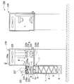
図3は、測定機230の一部の構成を示す部分断面図である。
図1に示すように、測定機230には、成形機220から排出されたワークWが投入される投入口231と、測定後のワークWが排出される排出口235とが設けられている。
図3に示すように、測定機230の投入口231は、測定機230のチャンバーの内側へ向って旋回可能なフラップ部232と、フラップ部232を旋回動作させる図示しない旋回駆動部とを備える。
フラップ部232によって、測定機230の投入口231は開閉可能となっており、フラップ部232によって投入口231が閉じられているときには、投入口231は気密に封止されている。
測定機230のチャンバーには、ワークWの形状を測定する形状測定部233と、チャンバーの内部の気体を攪拌するファン234とが設けられている。本実施形態では、測定機230のチャンバー内は所定温度の空気雰囲気に設定されている。
FIG. 3 is a partial cross-sectional view showing a partial configuration of the measuring instrument 230.
As shown in FIG. 1, the measuring machine 230 is provided with an inlet 231 into which the work W discharged from the molding machine 220 is input and an outlet 235 from which the measured work W is discharged.
As shown in FIG. 3, the insertion port 231 of the measuring device 230 includes a flap portion 232 that can turn toward the inside of the chamber of the measuring device 230, and a turning drive portion (not shown) that turns the flap portion 232.
The opening 231 of the measuring instrument 230 can be opened and closed by the flap portion 232, and when the insertion port 231 is closed by the flap portion 232, the insertion port 231 is hermetically sealed.
The chamber of the measuring device 230 is provided with a shape measuring unit 233 for measuring the shape of the workpiece W and a fan 234 for stirring the gas inside the chamber. In this embodiment, the inside of the chamber of the measuring device 230 is set to an air atmosphere at a predetermined temperature.

図1に示す排出口235は、上述の排出口222と同様の構成を有している。
測定機230は、投入口231を介して成形機220から搬送されたワークWを、所定温度の空気雰囲気下で形状測定部233により測定し、図示しないマニピュレータによって排出口235へと搬送するようになっている。
The discharge port 235 shown in FIG. 1 has the same configuration as the discharge port 222 described above.
The measuring machine 230 measures the workpiece W conveyed from the molding machine 220 via the input port 231 by the shape measuring unit 233 in an air atmosphere at a predetermined temperature, and conveys it to the discharge port 235 by a manipulator (not shown). It has become.

図1に示すように、洗浄機240には、測定機230から排出されたワークWが投入される投入口241および洗浄後のワークWが排出される排出口242が設けられている。洗浄機240における投入口241の構成は上述の投入口231の構成と同様であり、洗浄機240における排出口242の構成は上述の排出口222の構成と同様である。   As shown in FIG. 1, the cleaning machine 240 is provided with an input port 241 through which the work W discharged from the measuring device 230 is input and an output port 242 through which the cleaned work W is discharged. The configuration of the inlet 241 in the cleaning machine 240 is the same as the configuration of the inlet 231 described above, and the configuration of the outlet 242 in the cleaning machine 240 is the same as the configuration of the outlet 222 described above.

次に、搬送システム100の構成について説明する。
図1に示すように、搬送システム100は、素材供給機210と成形機220との間で素材(ワークW)の搬送を行う第1搬送システム100Aと、成形機220と測定機230との間でワークWの搬送を行う第2搬送システム100Bと、測定機230と洗浄機240との間でワークWの搬送を行う第3搬送システム100Cとを備える。
第1搬送システム100A、第2搬送システム100B、第3搬送システム100Cは同様の構成を有している。以下では第2搬送システム100Bについて詳述し、第2搬送システム100Bと同様の構成を有する第1搬送システム100Aおよび第3搬送システム100Cについての説明は省略する。
Next, the configuration of the transport system 100 will be described.
As shown in FIG. 1, the conveyance system 100 includes a first conveyance system 100 </ b> A that conveys a material (workpiece W) between a material supply machine 210 and a molding machine 220, and between the molding machine 220 and a measuring machine 230. The second transport system 100B that transports the workpiece W and the third transport system 100C that transports the workpiece W between the measuring device 230 and the washing machine 240.
The first transfer system 100A, the second transfer system 100B, and the third transfer system 100C have the same configuration. Below, the 2nd conveyance system 100B is explained in full detail, and description about the 1st conveyance system 100A and the 3rd conveyance system 100C which have the same composition as the 2nd conveyance system 100B is omitted.

第2搬送システム100Bは、搬送ボックス1と、成形機220の排出口222と測定機230の投入口231との間で搬送ボックス1を搬送する搬送装置110とを有する。   The second transport system 100 </ b> B includes a transport box 1, and a transport device 110 that transports the transport box 1 between the discharge port 222 of the molding machine 220 and the input port 231 of the measuring device 230.

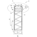
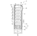
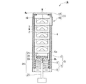
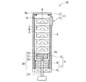
図4は、搬送ボックス1を示す部分断面図である。図5は、ワークWが格納されたトレー2を内部に収容した状態の搬送ボックス1を示す部分断面図である。
図1に示すように、搬送ボックス1は、成形機220から測定機230へワークWを搬送するために使用される容器である。
図4および図5に示すように、搬送ボックス1は、ワークWを格納する格納部3が形成されたトレー2と、トレー2とともにワークWを内部に収容する収容室4と、収容室4の容積を変化させる容積調整機構5と、収容室4を開閉可能且つ気密に封止する封止手段11とを備える。
FIG. 4 is a partial cross-sectional view showing the transport box 1. FIG. 5 is a partial cross-sectional view showing the transport box 1 in a state in which the tray 2 in which the workpieces W are stored is accommodated therein.
As shown in FIG. 1, the transport box 1 is a container used to transport the workpiece W from the molding machine 220 to the measuring machine 230.
As shown in FIGS. 4 and 5, the transport box 1 includes a tray 2 in which a storage unit 3 for storing the workpiece W is formed, a storage chamber 4 that stores the workpiece W together with the tray 2, and a storage chamber 4. A volume adjusting mechanism 5 that changes the volume and a sealing means 11 that can be opened and closed and hermetically seal the storage chamber 4 are provided.

図5に示すように、トレー2に形成された格納部3は、トレー2内でワークWが移動しないようにワークWを支えることができる形状となっており、ワークWの形状に合わせて適宜の形状とすることができる。本実施形態では、格納部3は、その内部にワークWを完全に収容できる形状に形成されている。
本実施形態のトレー2の外観形状は略直方体状である。本実施形態では、トレー2の格納部3にワークWを格納してもトレー2の外観形状は略直方体状である。本発明では、ワークWが格納された状態のトレー2が収容室4内で占有する体積を「包絡体積」と称する。本実施形態でいう包絡体積の詳細な定義については後述する。
As shown in FIG. 5, the storage portion 3 formed on the tray 2 has a shape that can support the workpiece W so that the workpiece W does not move in the tray 2. It can be made into the shape. In this embodiment, the storage part 3 is formed in the shape which can accommodate the workpiece | work W completely in the inside.
The external shape of the tray 2 of this embodiment is a substantially rectangular parallelepiped shape. In this embodiment, even if the workpiece W is stored in the storage unit 3 of the tray 2, the external shape of the tray 2 is a substantially rectangular parallelepiped shape. In the present invention, the volume occupied in the storage chamber 4 by the tray 2 in which the workpiece W is stored is referred to as “envelope volume”. The detailed definition of the envelope volume in this embodiment will be described later.

収容室4は、トレー2の外面に対して摺動可能に接する内寸の角筒状に形成されており、ワークWを受入れる上端開口4aが上端に形成されている。これにより、収容室4には、ワークWが格納されたトレー2が上端開口4aを通じて上から挿入可能になっている。なお、収容室4の形状および寸法は、トレー2の外観形状に基づいて決定されることが好ましい。収容室4内には、図5に示すように、収容室4の中心軸線方向にトレー2を重ねて複数収容することができる。   The storage chamber 4 is formed in a rectangular tube shape with an internal dimension that is slidably in contact with the outer surface of the tray 2, and an upper end opening 4 a for receiving the workpiece W is formed at the upper end. As a result, the tray 2 in which the workpieces W are stored can be inserted into the storage chamber 4 from above through the upper end opening 4a. The shape and dimensions of the storage chamber 4 are preferably determined based on the external shape of the tray 2. As shown in FIG. 5, a plurality of trays 2 can be accommodated in the storage chamber 4 in the direction of the central axis of the storage chamber 4.

本実施形態では、収容室4内で互いに重ねられた複数のトレー2における収容室4の中心軸線方向の長さ寸法Lに、収容室4を中心軸線方向から見たときの収容室4の内周面によって規定される空間の面積を掛け合わせて得られた体積が、本実施形態におけるトレー2の包絡体積である。なお、各トレー2が、収容室4の中心軸線方向に突出する突起およびこの突起に嵌る窪みを有する形状であって、突起および窪みにより複数のトレー2が連結されるような形状である場合には、上記長さ寸法Lは、トレー2における収容室4の中心軸線方向の実際の長さ寸法から、収容室4の中心軸線方向に測った上記突起の長さのうち上記窪みに挿入された分の長さが差し引かれた長さとなる。   In the present embodiment, the length L in the central axis direction of the storage chamber 4 in the plurality of trays 2 stacked on each other in the storage chamber 4 is the inside of the storage chamber 4 when the storage chamber 4 is viewed from the central axis direction. The volume obtained by multiplying the area of the space defined by the peripheral surface is the envelope volume of the tray 2 in this embodiment. In addition, when each tray 2 is a shape which has the protrusion which protrudes in the central-axis line direction of the storage chamber 4, and the hollow fitted to this protrusion, Comprising: It is a shape where several tray 2 is connected by a protrusion and a hollow. The length L is inserted into the recess of the length of the protrusion measured in the central axis direction of the storage chamber 4 from the actual length dimension of the tray 2 in the central axis direction of the storage chamber 4. The length of the minute is the subtracted length.

容積調整機構5は、収容室4の内部に配置された載置台6と、収容室4の中心軸線方向へ載置台6を移動させる台移動手段7とを備える。
載置台6は、収容室4の内周面に対して収容室4の中心軸線方向へ移動可能な略直方体状部材である。載置台6の上面6aには、ワークWが格納されたトレー2が載置される。載置台6の側面の形状は、収容室4の内周面の形状に倣っている。また、本実施形態では、載置台6の側面には図示しないシール材が固定されており、載置台6の外面と収容室4の内周面とは気密状態を維持したまま摺動可能になっている。
The volume adjustment mechanism 5 includes a mounting table 6 disposed inside the storage chamber 4 and a table moving means 7 that moves the mounting table 6 in the direction of the central axis of the storage chamber 4.
The mounting table 6 is a substantially rectangular parallelepiped member that is movable in the central axis direction of the storage chamber 4 with respect to the inner peripheral surface of the storage chamber 4. On the upper surface 6a of the mounting table 6, the tray 2 in which the workpieces W are stored is mounted. The shape of the side surface of the mounting table 6 follows the shape of the inner peripheral surface of the storage chamber 4. In this embodiment, a sealing material (not shown) is fixed to the side surface of the mounting table 6, and the outer surface of the mounting table 6 and the inner peripheral surface of the storage chamber 4 can slide while maintaining an airtight state. ing.

台移動手段7は、収容室4の底部に固定された固定部8と、固定部8と載置台6とに固定された付勢部材9とを備える。
固定部8は、収容室4の底部において付勢部材9を支持し、付勢部材9を介して載置台6を支持している。また、固定部8は、HEPAフィルターなどを介して収容室4における載置台6より下側の空間に空気を出入りさせる連通部8aを有している。
付勢部材9は、収容室4の上端開口4a側へ載置台6を押圧する圧縮コイルバネである。すなわち、付勢部材9は、トレー2を上端開口4aから収容室4内へ挿入する方向とは反対方向へ載置台6を付勢するようになっている。付勢部材9は、少なくとも載置台6の上面6aに載置されたトレー2が後述するストッパ10に当接するまで伸張するようにその形状および付勢力が設定されている。
The table moving means 7 includes a fixed portion 8 fixed to the bottom of the storage chamber 4, and a biasing member 9 fixed to the fixed portion 8 and the mounting table 6.
The fixed portion 8 supports the biasing member 9 at the bottom of the storage chamber 4 and supports the mounting table 6 via the biasing member 9. Moreover, the fixing | fixed part 8 has the communication part 8a which makes air flow in / out to the space below the mounting base 6 in the storage chamber 4 via a HEPA filter.
The urging member 9 is a compression coil spring that presses the mounting table 6 toward the upper end opening 4 a of the storage chamber 4. That is, the urging member 9 urges the mounting table 6 in a direction opposite to the direction in which the tray 2 is inserted into the storage chamber 4 from the upper end opening 4a. The shape and the urging force of the urging member 9 are set such that the urging member 9 extends at least until the tray 2 placed on the upper surface 6a of the placing table 6 comes into contact with a stopper 10 described later.

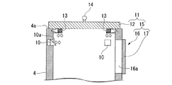
図7は、図4において符号Yで示す部分を拡大して示す拡大図である。
図7に示すように、収容室4の上端開口4aには、収容室4の中心軸線方向に対して直交する方向(以下、この方向を「収容室4の径方向」と称する。)に進退可能なストッパ10が設けられている。
ストッパ10は、収容室4の上端開口4aの近傍に複数配置されている。各ストッパ10は、収容室4の内面から内側へ向かって付勢されており、外力がかかっていない状態では収容室4の内面から内側へ突出している。ストッパ10において収容室4の上端開口4aに向けられた側には、収容室4の径方向内側へ向かうに従って収容室4の底へ向かうように傾斜して形成された傾斜面10aが設けられている。これにより、収容室4の上端開口4aを通じてトレー2(図5参照)を収容室4内に挿入するとストッパ10は収容室4の径方向外側へ移動して開き、トレー2がストッパ10を通過した後にはストッパ10が付勢力によって収容室4の径方向内側へ移動する。また、収容室4の内側に突出したストッパ10は、ワークWが格納されたトレー2を上端開口4aから収容室4の外側方向へ移動させる付勢部材9の付勢力に抗してトレー2を収容室4内に保持するようになっている。
FIG. 7 is an enlarged view showing a portion indicated by a symbol Y in FIG.
As shown in FIG. 7, the upper end opening 4 a of the storage chamber 4 advances and retreats in a direction orthogonal to the central axis direction of the storage chamber 4 (hereinafter, this direction is referred to as “the radial direction of the storage chamber 4”). A possible stopper 10 is provided.
A plurality of stoppers 10 are arranged in the vicinity of the upper end opening 4 a of the storage chamber 4. Each stopper 10 is urged inward from the inner surface of the storage chamber 4 and protrudes inward from the inner surface of the storage chamber 4 when no external force is applied. On the side of the stopper 10 facing the upper end opening 4 a of the storage chamber 4, there is provided an inclined surface 10 a formed so as to be inclined toward the bottom of the storage chamber 4 toward the inner side in the radial direction of the storage chamber 4. Yes. Accordingly, when the tray 2 (see FIG. 5) is inserted into the storage chamber 4 through the upper end opening 4a of the storage chamber 4, the stopper 10 moves to the outside in the radial direction of the storage chamber 4 and opens, and the tray 2 passes through the stopper 10. Later, the stopper 10 moves radially inward of the storage chamber 4 by the biasing force. Further, the stopper 10 protruding inside the storage chamber 4 resists the urging force of the urging member 9 that moves the tray 2 in which the workpiece W is stored from the upper end opening 4 a toward the outside of the storage chamber 4. It is held in the storage chamber 4.

図7に示すように、封止手段11は、収容室4の上端開口4aに着脱自在に取り付けられる蓋体12と、収容室4の上端開口4aの近傍でストッパ10と略同じ高さに配置された側方開閉部15とを備える。
蓋体12は、収容室4の内面に付勢力によって押し付けられる係止部13と、上述のロック部226に係合可能なフック14とを有する略矩形板状部材である。
係止部13とフック14とは互いに連結されており、ロック部226によってフック14を所定の方向へ押圧することにより係止部13は収容室4の内面から離間するようになっている。
As shown in FIG. 7, the sealing means 11 is disposed at substantially the same height as the stopper 10 in the vicinity of the lid body 12 detachably attached to the upper end opening 4 a of the storage chamber 4 and the upper end opening 4 a of the storage chamber 4. The side opening / closing part 15 is provided.
The lid 12 is a substantially rectangular plate-like member having a locking portion 13 that is pressed against the inner surface of the storage chamber 4 by a biasing force, and a hook 14 that can be engaged with the lock portion 226 described above.
The locking portion 13 and the hook 14 are connected to each other, and the locking portion 226 is separated from the inner surface of the storage chamber 4 by pressing the hook 14 in a predetermined direction by the lock portion 226.

なお、本実施形態では、係止部13は、収容室4の径方向外側へ向うに従って収容室4の底側へ向うテーパー形状の面を有し、収容室4には、係止部13に形成されたテーパー部分が挿入される溝が形成されている。係止部13のテーパー部分が溝に挿入されることにより蓋体12は収容室4の上端開口4aの端部に押し付けられ、これにより蓋体12は収容室4の上端開口4aを封止することができるようになっている。また、係止部13が収容室4の溝に挿入されている状態では蓋体12は収容室4から外れないようになっている。   In this embodiment, the locking portion 13 has a tapered surface that faces the bottom side of the storage chamber 4 as it goes outward in the radial direction of the storage chamber 4. A groove into which the formed tapered portion is inserted is formed. When the tapered portion of the locking portion 13 is inserted into the groove, the lid body 12 is pressed against the end portion of the upper end opening 4 a of the storage chamber 4, whereby the lid body 12 seals the upper end opening 4 a of the storage chamber 4. Be able to. Further, the lid 12 is prevented from being detached from the storage chamber 4 in a state where the locking portion 13 is inserted into the groove of the storage chamber 4.

側方開閉部15は、収容室4に収容されたトレー2を収容室4の径方向外側へ向かって引き出し可能な側方開口部16と、側方開口部16を封止可能な収容室フラップ17とを有する。
側方開口部16には、収容室4の外壁を構成する4面のうちの1面が矩形形状に切り取られた形状の引出口16aが形成されている。側方開口部16の引出口16aからは、ストッパ10に当接した状態で収容室4内に収容されたトレー2を1つ引き出すことができるようになっている。
The side opening / closing part 15 includes a side opening 16 capable of pulling out the tray 2 accommodated in the accommodation room 4 toward the radially outer side of the accommodation room 4, and a storage room flap capable of sealing the side opening 16. 17.
In the side opening 16, an outlet 16 a having a shape in which one of four surfaces constituting the outer wall of the storage chamber 4 is cut into a rectangular shape is formed. From the outlet 16 a of the side opening 16, one tray 2 accommodated in the accommodation chamber 4 can be pulled out while being in contact with the stopper 10.

次に、搬送ボックス1および搬送システム100の作用について説明する。
図1に示すように、処理システム200の動作時には、まず、素材供給機210から成形機220へ素材(ワークW)が搬送システム100Aによって搬送される。成形機220では、成形型228によって素材(ワークW)は所定の形状に成形される。次に、成形機220から測定機230へワークWが搬送システム100Bによって搬送される。測定機230では、形状測定部233によってワークWの形状が測定される。次に、測定機230から洗浄機240へワークWが搬送システム100Cによって搬送される。洗浄機240では、ワークWが洗浄される。
Next, operations of the transport box 1 and the transport system 100 will be described.
As shown in FIG. 1, when the processing system 200 operates, first, a material (work W) is conveyed from the material supply machine 210 to the molding machine 220 by the conveyance system 100A. In the molding machine 220, the material (work W) is molded into a predetermined shape by the molding die 228. Next, the workpiece W is conveyed from the molding machine 220 to the measuring machine 230 by the conveyance system 100B. In the measuring machine 230, the shape measuring unit 233 measures the shape of the workpiece W. Next, the workpiece W is transferred from the measuring machine 230 to the cleaning machine 240 by the transfer system 100C. In the cleaning machine 240, the workpiece W is cleaned.

以下では、成形機220から測定機230へワークWを搬送する搬送システム100Bの動作について説明する。なお、搬送システム100Aおよび搬送システム100Cの動作は搬送システム100Bの動作と同様であるので説明を省略する。
成形機220から測定機230へのワークWの搬送が開始する前は、成形機220の排出口222はシャッター225によって封止されている(図6参照)。これにより、成形機220のチャンバー内の窒素が排出口222から漏れることが防止されている。
成形機220から測定機230へワークWを搬送するときには、収容室4内が空の状態の搬送ボックス1(図4参照)を用意し、図1に示すように搬送ボックス1を搬送する搬送装置110により、または手作業により、空の搬送ボックス1を成形機220の排出口222に取り付ける。
Below, operation | movement of the conveyance system 100B which conveys the workpiece | work W from the molding machine 220 to the measuring machine 230 is demonstrated. The operations of the transfer system 100A and the transfer system 100C are the same as the operation of the transfer system 100B, and thus the description thereof is omitted.
Before the transfer of the workpiece W from the molding machine 220 to the measuring machine 230 starts, the discharge port 222 of the molding machine 220 is sealed by the shutter 225 (see FIG. 6). Thereby, nitrogen in the chamber of the molding machine 220 is prevented from leaking from the discharge port 222.
When the workpiece W is transferred from the molding machine 220 to the measuring machine 230, a transfer box 1 (see FIG. 4) in which the inside of the storage chamber 4 is empty is prepared, and a transfer apparatus that transfers the transfer box 1 as shown in FIG. The empty conveyance box 1 is attached to the discharge port 222 of the molding machine 220 by 110 or manually.

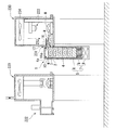
図8および図9は、搬送ボックス1を用いたワークWの搬送時における成形機220の動作を説明するための図である。
図8に示すように、成形機220の排出口222に設けられたアクチュエータ227は、ロック部226をフック14に係止させ、フック14に接続された係止部13を収容室4の内面から離間させる。これにより、蓋体12と収容室4との係合は解除される。
図9に示すように、アクチュエータ227は、シャッター225を上方へ引き上げ、これにより排出口222を開く。また、ロック部226がフック14に係合されているので、アクチュエータ227がシャッター225を引き上げることにより蓋体12も一体に引き上げられる。これにより、収容室4の上端開口4aが開かれる。
成形機220は、成形されたワークWをマニピュレータMによりトレー2の格納部3に格納し、ワークWが格納されたトレー2をカバー223の内部を通じて収容室4へと挿入する。
容積調整機構5は、ワークWが格納されたトレー2が収容室4内へ収容される動作によって、トレー2を収容する前における収容室4の初期容積から、トレー2が収容室4内で占有する包絡体積を初期容積に足した収容後容積まで、収容室4の容積を漸次増加させる。これにより、トレー2を収容室4に挿入した分だけ収容室4の容積が増加し、収容室4とチャンバーとの間における気体の出入りはほとんど発生しない。
8 and 9 are diagrams for explaining the operation of the molding machine 220 when the work W is transported using the transport box 1.
As shown in FIG. 8, the actuator 227 provided at the discharge port 222 of the molding machine 220 locks the lock portion 226 to the hook 14, and moves the lock portion 13 connected to the hook 14 from the inner surface of the storage chamber 4. Separate. As a result, the engagement between the lid 12 and the storage chamber 4 is released.
As shown in FIG. 9, the actuator 227 raises the shutter 225 upward, thereby opening the discharge port 222. Further, since the lock portion 226 is engaged with the hook 14, the lid body 12 is also lifted together by the actuator 227 pulling up the shutter 225. Thereby, the upper end opening 4a of the storage chamber 4 is opened.
The molding machine 220 stores the molded workpiece W in the storage unit 3 of the tray 2 by the manipulator M, and inserts the tray 2 storing the workpiece W into the storage chamber 4 through the inside of the cover 223.
The volume adjusting mechanism 5 occupies the tray 2 in the storage chamber 4 from the initial volume of the storage chamber 4 before storing the tray 2 by the operation of storing the tray 2 in which the workpiece W is stored in the storage chamber 4. The volume of the storage chamber 4 is gradually increased to the post-storage volume obtained by adding the envelope volume to be added to the initial volume. As a result, the volume of the storage chamber 4 is increased by the amount of insertion of the tray 2 into the storage chamber 4, and the gas enters and exits between the storage chamber 4 and the chamber.

図5に示すように、収容室4の内部には、収容室4の中心軸線方向に重ねて複数のトレー2が収容される。収容室4内にトレー2が収容されると、収容されるトレー2の数に応じて載置台6は底側へ押し込まれる。載置台6に固定された付勢部材9は載置台6を上端開口4a側へ付勢しているので、収容室4内に収容されたトレー2は、載置台6とストッパ10とに挟まれた状態で保持される。   As shown in FIG. 5, a plurality of trays 2 are accommodated inside the accommodation chamber 4 so as to overlap in the central axis direction of the accommodation chamber 4. When the tray 2 is stored in the storage chamber 4, the mounting table 6 is pushed to the bottom side according to the number of trays 2 to be stored. Since the biasing member 9 fixed to the mounting table 6 biases the mounting table 6 toward the upper end opening 4 a, the tray 2 accommodated in the storage chamber 4 is sandwiched between the mounting table 6 and the stopper 10. It is held in the state.

図10は、搬送ボックス1を用いたワークWの搬送時における測定機230の動作を説明するための図である。
図1および図10に示すように、成形機220においてワークWが内部に収容された搬送ボックス1は、蓋体12が再び上端開口4bに取り付けられた後、搬送装置110によって測定機230の投入口231まで搬送され、測定機230の投入口231に取り付けられる。さらに、測定機230のフラップ部232は測定機230のチャンバーの内側へ向かって開き、搬送ボックス1の側方開口部16に設けられた収容室フラップ17もチャンバーの内側へ向って同時に開く。これにより、測定機230のチャンバー内と収容室4内は連通する。
FIG. 10 is a diagram for explaining the operation of the measuring device 230 when the work W is transported using the transport box 1.
As shown in FIGS. 1 and 10, the transport box 1 in which the workpiece W is housed in the molding machine 220 is inserted into the measuring machine 230 by the transport device 110 after the lid 12 is attached to the upper end opening 4 b again. It is conveyed to the opening 231 and attached to the insertion opening 231 of the measuring machine 230. Further, the flap portion 232 of the measuring device 230 opens toward the inside of the chamber of the measuring device 230, and the storage chamber flap 17 provided in the side opening 16 of the transport box 1 also opens simultaneously toward the inside of the chamber. Thereby, the inside of the chamber of the measuring instrument 230 and the inside of the storage chamber 4 communicate.

続いて、収容室4内においてストッパ10に当接しているトレー2が、測定機230のチャンバー内へ引き込まれる。すると、引き込まれるトレー2の下に位置する他のトレー2は、付勢部材9が載置台6を上端開口4a側へ押圧する付勢力によって上方へ移動する。当該他のトレー2のうち最も上に位置するトレー2はストッパ10に当接して、側方開口部16の引出口16aから引き出すことができるようになる。   Subsequently, the tray 2 in contact with the stopper 10 in the storage chamber 4 is drawn into the chamber of the measuring device 230. Then, the other trays 2 positioned below the tray 2 to be drawn move upward by the biasing force of the biasing member 9 pressing the mounting table 6 toward the upper end opening 4a. Of the other trays 2, the uppermost tray 2 comes into contact with the stopper 10 and can be pulled out from the outlet 16 a of the side opening 16.

搬送ボックス1内の全てのトレー2が測定機230のチャンバー内に引き込まれたら、成形機220から測定機230へのワークWの搬送は終了する。成形機220から測定機230へのワークWの搬送が終了したあとは、必要に応じて、空の搬送ボックス1を再び成形機220の排出口222まで搬送し、上述したのと同様の動作によりワークWを測定機230へ搬送する。   When all the trays 2 in the transport box 1 are drawn into the chamber of the measuring machine 230, the transport of the workpiece W from the molding machine 220 to the measuring machine 230 ends. After conveyance of the workpiece W from the molding machine 220 to the measuring machine 230 is completed, the empty conveyance box 1 is conveyed again to the discharge port 222 of the molding machine 220 as necessary, and the same operation as described above is performed. The workpiece W is conveyed to the measuring device 230.

以上説明したように、本実施形態の搬送ボックス1および搬送システム100によれば、収容室4の容積を容積調整機構5が変化させるので、ワークWが内部に収容可能な最低限の容積となるように収容室4の容積を設定することができる。このため、チャンバーから取り出したワークWを収容室4内に収容する場合における当該チャンバーから収容室4への雰囲気の流入量を削減することができる。その結果、ワークWを搬送する先のチャンバー内における雰囲気の変動を抑えつつワークWを搬送することができる。   As described above, according to the transport box 1 and the transport system 100 of the present embodiment, the volume adjustment mechanism 5 changes the volume of the storage chamber 4, so that the work W has a minimum volume that can be accommodated therein. Thus, the volume of the storage chamber 4 can be set. For this reason, when the workpiece | work W picked out from the chamber is accommodated in the storage chamber 4, the inflow amount of the atmosphere from the said chamber to the storage chamber 4 can be reduced. As a result, the workpiece W can be transported while suppressing fluctuations in the atmosphere in the chamber to which the workpiece W is transported.

さらに、容積調整機構5が収容室4の容積を変化させることにより収容室4への雰囲気の流入量を削減できるので、収容室4内の気体を置換しなくても搬送先のチャンバーへの雰囲気の持込量は少ない。このため、搬送ボックス1の構成を簡素とすることができる。   Furthermore, since the volume adjustment mechanism 5 can change the volume of the storage chamber 4 to reduce the amount of atmosphere flowing into the storage chamber 4, the atmosphere in the transfer destination chamber can be replaced without replacing the gas in the storage chamber 4. There is little carry-in. For this reason, the structure of the conveyance box 1 can be simplified.

また、容積調整機構5が、ワークWが格納されたトレー2が収容室4内へ収容される動作によって収容室4の容積を漸次増加させるので、ワークWが格納されたトレー2と収容室4との隙間の大きさを最小限とすることができ、収容室4へのチャンバー内雰囲気の流入量をさらに抑えることができる。   Further, since the volume adjusting mechanism 5 gradually increases the volume of the storage chamber 4 by the operation of storing the tray 2 in which the workpiece W is stored in the storage chamber 4, the tray 2 and the storage chamber 4 in which the workpiece W is stored. And the amount of the atmosphere in the chamber into the storage chamber 4 can be further suppressed.

また、容積調整機構5が載置台6と台移動手段7とを備えており、ワークWが格納されたトレー2が収容室4内へ収容される動作によって載置台6が収容室4の中心軸線方向で底側へ漸次移動するようになっているので、ワークWが格納されたトレー2を収容室4内で載置台6上に保持することができる。これにより、ワークWが格納されたトレー2を安定して搬送することができる。   Further, the volume adjusting mechanism 5 includes a mounting table 6 and a table moving means 7, and the mounting table 6 is moved along the central axis of the storage chamber 4 by the operation of storing the tray 2 storing the workpieces W in the storage chamber 4. The tray 2 in which the workpieces W are stored can be held on the mounting table 6 in the storage chamber 4 because the workpiece W is gradually moved to the bottom side in the direction. Thereby, the tray 2 in which the workpieces W are stored can be stably conveyed.

また、収容室4内へのワークWの収容方向とは反対方向へ載置台6を付勢する付勢部材9が台移動手段7に設けられているので、収容室4の容積が小さくなる方向への力が付勢部材9から載置台6へかかる。このため、チャンバー内の雰囲気が流入する隙間が最小限となる位置に載置台6を保持することができる。   Further, since the urging member 9 for urging the mounting table 6 in the direction opposite to the direction in which the workpiece W is accommodated in the accommodation chamber 4 is provided in the table moving means 7, the volume of the accommodation chamber 4 is reduced. Is applied from the biasing member 9 to the mounting table 6. For this reason, the mounting table 6 can be held at a position where the gap into which the atmosphere in the chamber flows is minimized.

また、収容室4の上端開口4aに設けられたストッパ10により、ワークWが上端開口4aから外に押し出されることが防止されている。また、付勢部材9が載置台6を押圧して載置台6とストッパ10との間にワークWが挟みこまれて保持されるので、搬送ボックス1を用いてワークWを搬送するときに収容室4内でワークWの位置がずれるのを抑えることができる。これにより、ワークW同士が衝突したり、ワークWが格納されたケースが収容室4の内面に衝突してワークWに衝撃が伝わったりするのを抑えることができる。   Moreover, the stopper 10 provided in the upper end opening 4a of the storage chamber 4 prevents the workpiece W from being pushed out of the upper end opening 4a. Further, since the work W is sandwiched and held between the placing table 6 and the stopper 10 by the urging member 9 pressing the placing table 6, it is accommodated when the work W is transported using the transport box 1. It is possible to prevent the position of the workpiece W from shifting in the chamber 4. Thereby, it is possible to prevent the workpieces W from colliding with each other or the case in which the workpiece W is stored colliding with the inner surface of the storage chamber 4 and the impact being transmitted to the workpiece W.

(第2実施形態)
次に、本発明の第2実施形態の搬送ボックスについて説明する。
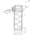
図11および図12は、本実施形態の搬送ボックス1Aの構成を示す部分断面図である。
本実施形態の搬送ボックス1Aは、収容室4内の圧力を調整する圧力調整機構20をさらに備える点が上述の搬送ボックス1と異なっている。
(Second Embodiment)
Next, a transport box according to a second embodiment of the present invention will be described.
11 and 12 are partial cross-sectional views showing the configuration of the transport box 1A of the present embodiment.
The transport box 1A of this embodiment is different from the transport box 1 described above in that it further includes a pressure adjustment mechanism 20 that adjusts the pressure in the storage chamber 4.

圧力調整機構20は、載置台6の上面6aに開口され載置台6の内部がくりぬかれた形状のシリンダー部21と、シリンダー部21の内周面に密着した板状のピストン22と、ピストン22に一端が連結された連結棒23とを備える。   The pressure adjustment mechanism 20 includes a cylinder portion 21 having a shape opened in the upper surface 6 a of the mounting table 6 and the interior of the mounting table 6 being hollowed out, a plate-like piston 22 in close contact with the inner peripheral surface of the cylinder portion 21, and a piston 22. And a connecting rod 23 having one end connected thereto.

載置台6には、連結棒23が貫通する貫通孔6bが形成されている。さらに、連結棒23と載置台6とは貫通孔6bの部分でねじ嵌合している。すなわち、連結棒23をその中心軸線回りに回転させることにより、連結棒23に連結されたピストン22をシリンダー部21内で移動させることができるようになっている。
また、シリンダー部21の底面とピストン22の下面との間には弾性部材24が介在されている。
The mounting table 6 is formed with a through hole 6b through which the connecting rod 23 passes. Furthermore, the connecting rod 23 and the mounting table 6 are screw-fitted at the through hole 6b. In other words, the piston 22 connected to the connecting rod 23 can be moved in the cylinder portion 21 by rotating the connecting rod 23 about its central axis.
An elastic member 24 is interposed between the bottom surface of the cylinder portion 21 and the lower surface of the piston 22.

図11および図12に示すように、圧力調整機構20は、連結棒23を回転させることにより、容積調整機構5とは独立して収容室4の容積を変化させるようになっている。
本実施形態では、封止手段11により収容室4内が封止状態とされているときに、例えば図11に示すようにシリンダー部21の底面に近い位置にピストン22が位置している状態から図12に示すように載置台6の上面6aに近い位置にピストン22を移動させると、収容室4の容積が小さくなることによって収容室4の内圧が上がる。逆に、図12に示すように載置台6の上面6aに近い位置にピストン22が位置している状態から図11に示すようにシリンダー部21の底面側へピストン22を移動させると、収容室4の容積が大きくなることによって収容室4の内圧が下がる。
As shown in FIGS. 11 and 12, the pressure adjusting mechanism 20 changes the volume of the storage chamber 4 independently of the volume adjusting mechanism 5 by rotating the connecting rod 23.
In the present embodiment, when the inside of the storage chamber 4 is sealed by the sealing means 11, for example, from the state where the piston 22 is located at a position close to the bottom surface of the cylinder portion 21 as shown in FIG. 11. As shown in FIG. 12, when the piston 22 is moved to a position close to the upper surface 6 a of the mounting table 6, the internal pressure of the storage chamber 4 increases as the volume of the storage chamber 4 decreases. Conversely, when the piston 22 is moved from the state where the piston 22 is located near the top surface 6a of the mounting table 6 as shown in FIG. 12 to the bottom surface side of the cylinder portion 21 as shown in FIG. As the volume of 4 increases, the internal pressure of the storage chamber 4 decreases.

上述した構成の搬送ボックス1Aの作用について説明する。なお、以下では、成形機220のチャンバー内のガス純度およびクリーンレベルが測定機230のチャンバー内のガス純度およびクリーンレベルよりも高い場合に、成形機220から測定機230へワークWを搬送する例を示す。   The operation of the transport box 1A configured as described above will be described. In the following, when the gas purity and clean level in the chamber of the molding machine 220 are higher than the gas purity and clean level in the chamber of the measuring machine 230, an example of conveying the workpiece W from the molding machine 220 to the measuring machine 230. Indicates.

本実施形態の搬送ボックス1Aの使用時には、例えば図1に示す第1実施形態と同様に成形機220から測定機230へワークWを搬送する場合、ワークWが格納されたケースを成形機220の排出口222から収容室4内へ収容したときには図12に示すようにピストン22を載置台6の底面に近い位置にしておく。
その後、搬送ボックス1を測定機230の投入口231に接続する前に、連結棒23を回転させてピストン22をシリンダー部21の上面6a側へ移動させる。これにより、収容室4の内部は正圧状態となる。
圧力調整機構20によって調整可能な収容室4の内圧は、常圧に対して±20Pa程度の範囲とされている。
When using the transport box 1A of the present embodiment, for example, when the work W is transported from the molding machine 220 to the measuring machine 230 as in the first embodiment shown in FIG. When housed in the housing chamber 4 from the discharge port 222, the piston 22 is placed close to the bottom surface of the mounting table 6 as shown in FIG.
Thereafter, before connecting the transport box 1 to the insertion port 231 of the measuring device 230, the connecting rod 23 is rotated to move the piston 22 to the upper surface 6 a side of the cylinder portion 21. Thereby, the inside of the storage chamber 4 is in a positive pressure state.
The internal pressure of the storage chamber 4 that can be adjusted by the pressure adjusting mechanism 20 is in a range of about ± 20 Pa with respect to the normal pressure.

収容室4内が正圧状態のまま収容室4内と搬送ボックス1を測定機230のチャンバー内とを連通させると、収容室4内が常圧である場合と比較してチャンバーから収容室4へ移動する気体の量は少ない。例えば測定機230のチャンバー内が常圧である場合には、収容室4内の気体がチャンバー内へ移動するので、チャンバー内の気体が収容室4内へ流入することが防止される。   When the inside of the storage chamber 4 and the inside of the transport box 1 are communicated with the inside of the chamber of the measuring device 230 while the inside of the storage chamber 4 is in a positive pressure state, the storage chamber 4 is moved from the chamber to the case where the inside of the storage chamber 4 is at normal pressure. The amount of gas moving to is small. For example, when the inside of the chamber of the measuring device 230 is at normal pressure, the gas in the storage chamber 4 moves into the chamber, so that the gas in the chamber is prevented from flowing into the storage chamber 4.

本実施形態の搬送ボックス1Aによれば、圧力調整機構20によって収容室4内の圧力を調整することができるので、チャンバー内から収容室4へ雰囲気が流入するのをさらに抑えることができる。これにより、収容室4内がクリーンレベルの悪い雰囲気やガス純度の低い雰囲気に汚染されることがなく、次に収容室4が成形機220と接続されたときにも成形機220のチャンバー内の雰囲気の変動を抑えることができる。   According to the transport box 1A of the present embodiment, the pressure in the storage chamber 4 can be adjusted by the pressure adjustment mechanism 20, so that the atmosphere can be further prevented from flowing into the storage chamber 4 from within the chamber. Thereby, the inside of the storage chamber 4 is not contaminated with an atmosphere with a poor clean level or an atmosphere with a low gas purity, and when the storage chamber 4 is connected to the molding machine 220 next time, The change in atmosphere can be suppressed.

また、圧力調整機構20が、収容室4の容積を容積調整機構5と独立して変化させるので、容積調整機構5によって収容室4の容積が設定されたあとに容積調整機構5を動かすことなく圧力調整機構20によって収容室4の容積を変化させることができる。
さらに、これにより、載置台6とストッパ10との間にトレー2が挟みこまれた状態が維持されるので、搬送中にトレー2がずれることを防止することができる。
Further, since the pressure adjustment mechanism 20 changes the volume of the storage chamber 4 independently of the volume adjustment mechanism 5, the volume adjustment mechanism 5 is not moved after the volume adjustment mechanism 5 sets the volume of the storage chamber 4. The volume of the storage chamber 4 can be changed by the pressure adjustment mechanism 20.
Further, this maintains the state in which the tray 2 is sandwiched between the mounting table 6 and the stopper 10, so that it is possible to prevent the tray 2 from being displaced during conveyance.

なお、本実施形態では、成形機220のチャンバー雰囲気のガス純度とクリーンレベルが測定機230のクリーンレベルよりも高いため、搬送ボックス1Aの収容室4が正圧のまま測定機230のチャンバーと連通させる構成となっている。複数の処理システム間のガス純度とクリーンレベルの関係によっては、ガス純度とクリーンレベルの高い処理システム側への気体の移動を少なくするように、圧力調整機構20によって収容室4内の圧力を負圧にすることもできる。   In this embodiment, since the gas purity and clean level of the chamber atmosphere of the molding machine 220 are higher than the clean level of the measuring machine 230, the container 4 of the transport box 1A communicates with the chamber of the measuring machine 230 while maintaining a positive pressure. It is the composition which makes it. Depending on the relationship between the gas purity and the clean level between the plurality of processing systems, the pressure adjustment mechanism 20 reduces the pressure in the storage chamber 4 so as to reduce the movement of gas toward the processing system having a high gas purity and clean level. It can also be pressure.

(変形例1)
次に、第2実施形態の搬送ボックスの変形例について説明する。
図13は、本変形例の搬送ボックス1Bを示す部分断面図である。
図13に示すように、本変形例の搬送ボックス1Bは、圧力調整機構20に代えて圧力調整機構20Aを備える点で上述の搬送ボックス1Aとは構成が異なっている。
(Modification 1)
Next, a modified example of the transport box of the second embodiment will be described.
FIG. 13 is a partial cross-sectional view showing a transport box 1B according to this modification.
As shown in FIG. 13, the transport box 1 </ b> B of the present modification is different in configuration from the transport box 1 </ b> A described above in that a pressure adjustment mechanism 20 </ b> A is provided instead of the pressure adjustment mechanism 20.

圧力調整機構20Aは、収容室4の内部と連通された圧力調整室21Aと、圧力調整室21Aの容積を変化させる容積変更手段25Aと、を備える。
圧力調整室21Aは、収容室4の外壁を貫通する貫通孔4bを通じて収容室4の内部と連通されており、収容室4の外壁に固定されている。
容積変更手段25Aは、圧力調整室21Aの内壁面に沿って摺動するピストン22Aと、ピストン22Aを圧力調整室21A内で移動させるレバー23Aとを備える。本変形例では、レバー23Aを動作させることによりピストン22Aが圧力調整室21A内で移動し、圧力調整室21Aの容積を変化させるようになっている。これにより、圧力調整室21Aと連通された収容室4内の圧力がレバー23Aの操作に基づいて変化する。
このような構成であっても、上述の第2実施形態の搬送ボックス1Aと同様の効果を奏する。
なお、圧力調整室21Aは載置台6の内部に設けられていても構わない。
The pressure adjustment mechanism 20A includes a pressure adjustment chamber 21A that communicates with the inside of the storage chamber 4, and a volume changing unit 25A that changes the volume of the pressure adjustment chamber 21A.
The pressure adjustment chamber 21 </ b> A communicates with the inside of the storage chamber 4 through a through hole 4 b that penetrates the outer wall of the storage chamber 4, and is fixed to the outer wall of the storage chamber 4.
The volume changing means 25A includes a piston 22A that slides along the inner wall surface of the pressure adjusting chamber 21A, and a lever 23A that moves the piston 22A within the pressure adjusting chamber 21A. In this modification, by operating the lever 23A, the piston 22A moves in the pressure adjustment chamber 21A, and the volume of the pressure adjustment chamber 21A is changed. Thereby, the pressure in the accommodation chamber 4 communicated with the pressure adjustment chamber 21A changes based on the operation of the lever 23A.
Even if it is such a structure, there exists an effect similar to the conveyance box 1A of the above-mentioned 2nd Embodiment.
Note that the pressure adjustment chamber 21 </ b> A may be provided inside the mounting table 6.

以上、本発明の実施形態について図面を参照して詳述したが、具体的な構成はこの実施形態に限られるものではなく、本発明の要旨を逸脱しない範囲の設計変更等も含まれる。
本発明の搬送ボックス1における収容室4の他の構成例について説明する。
図14(a)および図14(b)は、本発明の搬送ボックス1の他の構成例を示す部分断面図である。図15(a)および図15(b)は、本発明の搬送ボックス1のさらに他の構成例を示す部分断面図である。なお、図14(a)および図15(a)はトレー2が内部に収容された状態を示し、図14(b)および図15(b)はトレー2が収容されていない状態を示している。
As mentioned above, although embodiment of this invention was explained in full detail with reference to drawings, the concrete structure is not restricted to this embodiment, The design change etc. of the range which does not deviate from the summary of this invention are included.
The other structural example of the storage chamber 4 in the conveyance box 1 of this invention is demonstrated.
FIG. 14A and FIG. 14B are partial cross-sectional views showing other configuration examples of the transport box 1 of the present invention. FIG. 15A and FIG. 15B are partial cross-sectional views showing still another configuration example of the transport box 1 of the present invention. 14 (a) and 15 (a) show a state in which the tray 2 is accommodated therein, and FIGS. 14 (b) and 15 (b) show a state in which the tray 2 is not accommodated. .

図14(a)および図14(b)に示すように、本発明の搬送ボックス1の他の構成例としては、収容室4に代えて、直径が異なる複数の角筒あるいは円筒からなる筒部材4Aa、筒部材4Ab、筒部材4Ac、筒部材4Ad、および筒部材4Aeが同軸状に配置された収容室4Aを備え、収容室4Aが中心軸線方向に伸縮することによって収容室4Aの容積が変化する構成を挙げることができる。   As shown in FIGS. 14 (a) and 14 (b), as another configuration example of the transport box 1 of the present invention, instead of the storage chamber 4, a cylindrical member made of a plurality of rectangular tubes or cylinders having different diameters. 4Aa, cylinder member 4Ab, cylinder member 4Ac, cylinder member 4Ad, and cylinder member 4Ae are provided with a storage chamber 4A arranged coaxially, and the volume of the storage chamber 4A changes as the storage chamber 4A expands and contracts in the direction of the central axis. The structure to do can be mentioned.

また、図15(a)および図15(b)に示すように、本発明の搬送ボックス1のさらに他の構成例としては、収容室4に代えて、中心軸線方向い伸縮するベローズ形状の外壁を有する収容室4Bを備え、収容室4Bが中心軸線方向に伸縮することによって収容室4Bの容積が変化する構成を挙げることもできる。ベローズ形状の外壁は、樹脂など伸縮性を有する材料によって形成されていることが好ましい。   As shown in FIGS. 15 (a) and 15 (b), as still another configuration example of the transport box 1 of the present invention, a bellows-shaped outer wall that expands and contracts in the direction of the central axis is used instead of the storage chamber 4. There can also be mentioned a configuration in which the volume of the storage chamber 4B is changed by the expansion and contraction of the storage chamber 4B in the central axis direction. The bellows-shaped outer wall is preferably formed of a stretchable material such as a resin.

また、本発明の搬送ボックス1における設計変更として、ワークWやトレー2が軽量であれば固定部8と載置台6とを連結する付勢部材9としてスポンジが採用されていてもよい。また、ワークWやトレー2が重く圧縮コイルバネではワークWやトレー2を支えきれない場合には、付勢部材9に代えてエアシリンダなどの直動機構が採用されてもよい。   Further, as a design change in the transport box 1 of the present invention, a sponge may be employed as the biasing member 9 that connects the fixed portion 8 and the mounting table 6 if the workpiece W or the tray 2 is lightweight. Further, when the workpiece W or the tray 2 is heavy and the compression coil spring cannot support the workpiece W or the tray 2, a linear motion mechanism such as an air cylinder may be employed instead of the biasing member 9.

また、上述の各実施形態ではワークWは光学素子を製造するためのワークWである例を示したが、他のワークWを搬送する場合でも本発明の搬送ボックス1および搬送システム100を好適に適用することができる。   In each of the above embodiments, the work W is an example of a work W for manufacturing an optical element. However, even when another work W is transported, the transport box 1 and the transport system 100 of the present invention are preferably used. Can be applied.

なお、上述の本実施形態では、排出口222と投入口231との間における搬送ボックス1の搬送が搬送装置110によって行われる例を示したが、排出口222と投入口231との間における搬送ボックス1の搬送は、手作業によって行われてもよい。   In the above-described embodiment, an example in which the transport box 110 transports the transport box 1 between the discharge port 222 and the input port 231 has been described. However, transport between the discharge port 222 and the input port 231 is performed. The conveyance of the box 1 may be performed manually.

1、1A、1B 搬送ボックス
2 トレー
3 格納部
4、4A、4B 収容室
4a 上端開口(開口)
5 容積調整機構
6 載置台
7 台移動手段
9 付勢部材
10 ストッパ
11 封止手段
20、20A 圧力調整機構
21A 圧力調整室
100 搬送システム
110 搬送装置
200 処理システム
210 素材供給機
220 成形機(第1処理システム)
230 測定機(第2処理システム)
240 洗浄機(第3処理システム)
W ワーク
1, 1A, 1B Transport box 2 Tray 3 Storage unit 4, 4A, 4B Storage chamber 4a Upper end opening (opening)
DESCRIPTION OF SYMBOLS 5 Volume adjustment mechanism 6 Mounting base 7 Stand moving means 9 Energizing member 10 Stopper 11 Sealing means 20, 20A Pressure adjustment mechanism 21A Pressure adjustment chamber 100 Conveyance system 110 Conveyance apparatus 200 Processing system 210 Material supply machine 220 Molding machine (1st Processing system)
230 Measuring machine (second processing system)
240 washer (third processing system)
W Work

Claims (10)

ワークに対して処理を行う複数の処理システムにおける第1処理システムから第2処理システムへ前記ワークを搬送するために使用される搬送ボックスであって、
前記ワークを内部に収容する収容室と、
前記収容室の容積を変化させる容積調整機構と、
前記収容室を開閉可能且つ気密に封止する封止手段と、
を備えることを特徴とする搬送ボックス。
A transport box used for transporting the work from a first processing system to a second processing system in a plurality of processing systems for processing the work;
A storage chamber for storing the workpiece therein;
A volume adjustment mechanism for changing the volume of the storage chamber;
Sealing means for opening and closing the storage chamber and sealing hermetically;
A transport box comprising:
請求項1に記載の搬送ボックスであって、
前記ワークを格納する格納部が形成されたトレーをさらに備え、
前記容積調整機構は、前記ワークが格納された前記トレーが前記収容室内へ収容される動作によって、当該トレーを収容する前における前記収容室の初期容積から、当該トレーが前記収容室内で占有する包絡体積を前記初期容積に足した収容後容積まで、前記収容室の容積を漸次増加させる
ことを特徴とする搬送ボックス。
The transport box according to claim 1,
It further comprises a tray in which a storage unit for storing the workpiece is formed,
The volume adjusting mechanism includes an envelope that the tray occupies in the accommodation chamber from an initial volume of the accommodation chamber before the tray is accommodated by an operation in which the tray storing the workpiece is accommodated in the accommodation chamber. The transfer box, wherein the volume of the storage chamber is gradually increased to a post-storage volume obtained by adding the volume to the initial volume.
請求項2に記載の搬送ボックスであって、
前記収容室は、前記トレーの外面に対して摺動可能に接する内寸の筒状に形成されており、
前記容積調整機構は、
前記収容室の内周面に対して前記収容室の中心軸線方向へ移動可能であって前記ワークが載置される載置台と、
前記載置台を前記中心軸線方向へ移動させる台移動手段と、
を備える
ことを特徴とする搬送ボックス。
The transport box according to claim 2,
The storage chamber is formed in a cylindrical shape with an inner dimension that slidably contacts the outer surface of the tray,
The volume adjustment mechanism is
A mounting table that is movable in the direction of the central axis of the storage chamber with respect to the inner peripheral surface of the storage chamber and on which the workpiece is mounted;
A table moving means for moving the mounting table in the direction of the central axis;
A transport box comprising:
請求項3に記載の搬送ボックスであって、
前記台移動手段は、前記収容室内へ前記ワークを収容するときの前記ワークの移動方向とは反対方向へ前記載置台を付勢する付勢部材を有することを特徴とする搬送ボックス。
The transport box according to claim 3,
The transport box, wherein the table moving means includes a biasing member that biases the mounting table in a direction opposite to a moving direction of the workpiece when the workpiece is stored in the storage chamber.
請求項4に記載の搬送ボックスであって、
前記収容室は、前記ワークを受入れる開口が形成され、
前記開口には、前記開口から前記収容室の外側方向へ前記ワークを移動させる前記付勢部材の付勢力に抗するストッパが設けられていることを特徴とする搬送ボックス。
The transport box according to claim 4,
The accommodation chamber has an opening for receiving the workpiece,
A transport box, wherein the opening is provided with a stopper that resists the urging force of the urging member that moves the workpiece from the opening toward the outside of the storage chamber.
請求項1から請求項5のいずれか一項に記載の搬送ボックスであって、
前記収容室内の圧力を調整する圧力調整機構をさらに備えることを特徴とする搬送ボックス。
It is a conveyance box as described in any one of Claims 1-5,
The transport box further comprising a pressure adjusting mechanism for adjusting the pressure in the storage chamber.
請求項6に記載の搬送ボックスであって、
前記圧力調整機構は、前記収容室の容積を前記容積調整機構とは独立して変化させることを特徴とする搬送ボックス。
The transport box according to claim 6,
The transport box, wherein the pressure adjusting mechanism changes a volume of the storage chamber independently of the volume adjusting mechanism.
請求項6に記載の搬送ボックスであって、
前記圧力調整機構は、
前記収容室の内部と連通された圧力調整室と、
前記圧力調整室の容積を変化させる容積変更手段と、
を備えることを特徴とする搬送ボックス。
The transport box according to claim 6,
The pressure adjustment mechanism is
A pressure adjusting chamber communicated with the interior of the containing chamber;
Volume changing means for changing the volume of the pressure adjusting chamber;
A transport box comprising:
請求項8に記載の搬送ボックスであって、
前記圧力調整室は前記載置台に形成されていることを特徴とする搬送ボックス。
The transport box according to claim 8,
The transfer box, wherein the pressure adjusting chamber is formed on the mounting table.
請求項1から9のいずれか一項に記載の搬送ボックスと、
前記第1処理システムから前記第2処理システムへ前記搬送ボックスを搬送する搬送装置と、
を備えることを特徴とする搬送システム。
A transport box according to any one of claims 1 to 9,
A transport device for transporting the transport box from the first processing system to the second processing system;
A conveyance system comprising:
JP2011002395A 2011-01-07 2011-01-07 Conveyance box and conveyance system Withdrawn JP2012144263A (en)

Priority Applications (1)

Application Number Priority Date Filing Date Title
JP2011002395A JP2012144263A (en) 2011-01-07 2011-01-07 Conveyance box and conveyance system

Applications Claiming Priority (1)

Application Number Priority Date Filing Date Title
JP2011002395A JP2012144263A (en) 2011-01-07 2011-01-07 Conveyance box and conveyance system

Publications (1)

Publication Number Publication Date
JP2012144263A true JP2012144263A (en) 2012-08-02

Family

ID=46788278

Family Applications (1)

Application Number Title Priority Date Filing Date
JP2011002395A Withdrawn JP2012144263A (en) 2011-01-07 2011-01-07 Conveyance box and conveyance system

Country Status (1)

Country Link
JP (1) JP2012144263A (en)

Similar Documents

Publication Publication Date Title
EP3360156B1 (en) Humidity control in semiconductor systems
JP5925474B2 (en) Wafer processing equipment
KR101753920B1 (en) Purge device and load port
CN100365794C (en) Substrate processing device
TW537998B (en) System for transporting substrates
TWI420617B (en) Vorrichtung zur lagerung von objekten aus dem bereich der fertigung von elektronischen bauteilen
US8777540B2 (en) Apparatus for storing contamination-sensitive flat articles, in particular for storing semiconductor wafers
KR101888236B1 (en) A pressure­controlled wafer carrier and wafer transport system
JP4012190B2 (en) Closed container lid opening and closing system and opening and closing method
US10273579B2 (en) Apparatus for processing two or more substrates in a batch process
TW201620065A (en) Loading port and loading port atmoshpere substitution method
JP4829978B2 (en) Thin plate storage and conveyance system and reticle case using the same
JP2011124565A (en) System and method for vacuum processing of semiconductor substrate to be processed
JP2011124564A (en) System and method for vacuum processing of semiconductor substrate to be processed
EP3343597B1 (en) Storage device and storage method
JP6374878B2 (en) Station and method for measuring particle contamination of transport carriers that transport and store semiconductor substrates at atmospheric pressure
US5664679A (en) Transport container for wafer-shaped objects
CN112714950B (en) Pin lifting device
JP2007335556A (en) Conveyance system
JP2010267761A (en) Substrate storing container
KR102300629B1 (en) Apparatus for storing gas cylinders
KR102534814B1 (en) Load port apparatus and method of driving the same
JP2012144263A (en) Conveyance box and conveyance system
US20120076619A1 (en) Transport mechanism, transport jig and transport truck
JP2015076473A (en) Substrate treatment apparatus

Legal Events

Date Code Title Description
A300 Withdrawal of application because of no request for examination

Free format text: JAPANESE INTERMEDIATE CODE: A300

Effective date: 20140401