JP2012144246A - Tire pressure monitoring system - Google Patents
Tire pressure monitoring system Download PDFInfo
- Publication number
- JP2012144246A JP2012144246A JP2011275529A JP2011275529A JP2012144246A JP 2012144246 A JP2012144246 A JP 2012144246A JP 2011275529 A JP2011275529 A JP 2011275529A JP 2011275529 A JP2011275529 A JP 2011275529A JP 2012144246 A JP2012144246 A JP 2012144246A
- Authority
- JP
- Japan
- Prior art keywords
- tire
- pressure
- chamber
- antenna
- pressure sensor
- Prior art date
- Legal status (The legal status is an assumption and is not a legal conclusion. Google has not performed a legal analysis and makes no representation as to the accuracy of the status listed.)
- Pending
Links
- 238000012544 monitoring process Methods 0.000 title description 7
- 238000004891 communication Methods 0.000 claims abstract description 32
- 238000012806 monitoring device Methods 0.000 claims abstract description 9
- 238000007789 sealing Methods 0.000 claims abstract description 5
- 239000000463 material Substances 0.000 claims description 11
- 230000004913 activation Effects 0.000 claims description 5
- 239000012777 electrically insulating material Substances 0.000 claims description 5
- 239000004020 conductor Substances 0.000 claims description 4
- 239000003566 sealing material Substances 0.000 description 6
- 238000005219 brazing Methods 0.000 description 2
- 238000005266 casting Methods 0.000 description 2
- 238000013016 damping Methods 0.000 description 2
- 230000006872 improvement Effects 0.000 description 2
- 238000004519 manufacturing process Methods 0.000 description 2
- 239000007769 metal material Substances 0.000 description 2
- 230000004048 modification Effects 0.000 description 2
- 238000012986 modification Methods 0.000 description 2
- 238000000465 moulding Methods 0.000 description 2
- 230000009467 reduction Effects 0.000 description 2
- 238000003466 welding Methods 0.000 description 2
- RYGMFSIKBFXOCR-UHFFFAOYSA-N Copper Chemical compound [Cu] RYGMFSIKBFXOCR-UHFFFAOYSA-N 0.000 description 1
- HBBGRARXTFLTSG-UHFFFAOYSA-N Lithium ion Chemical compound [Li+] HBBGRARXTFLTSG-UHFFFAOYSA-N 0.000 description 1
- 230000004308 accommodation Effects 0.000 description 1
- 238000007792 addition Methods 0.000 description 1
- 238000004026 adhesive bonding Methods 0.000 description 1
- 230000005540 biological transmission Effects 0.000 description 1
- 229910052802 copper Inorganic materials 0.000 description 1
- 239000010949 copper Substances 0.000 description 1
- 238000005520 cutting process Methods 0.000 description 1
- 230000000694 effects Effects 0.000 description 1
- 239000013013 elastic material Substances 0.000 description 1
- 230000005611 electricity Effects 0.000 description 1
- 238000005265 energy consumption Methods 0.000 description 1
- 239000011521 glass Substances 0.000 description 1
- 238000010438 heat treatment Methods 0.000 description 1
- 239000007788 liquid Substances 0.000 description 1
- 229910001416 lithium ion Inorganic materials 0.000 description 1
- 238000000034 method Methods 0.000 description 1
- 230000002093 peripheral effect Effects 0.000 description 1
- 238000012545 processing Methods 0.000 description 1
- 230000001681 protective effect Effects 0.000 description 1
- 230000000630 rising effect Effects 0.000 description 1
- 230000035939 shock Effects 0.000 description 1
- 239000007779 soft material Substances 0.000 description 1
- 238000005476 soldering Methods 0.000 description 1
- 238000003860 storage Methods 0.000 description 1
- 238000009281 ultraviolet germicidal irradiation Methods 0.000 description 1
Images
Classifications
-
- B—PERFORMING OPERATIONS; TRANSPORTING
- B60—VEHICLES IN GENERAL
- B60C—VEHICLE TYRES; TYRE INFLATION; TYRE CHANGING; CONNECTING VALVES TO INFLATABLE ELASTIC BODIES IN GENERAL; DEVICES OR ARRANGEMENTS RELATED TO TYRES
- B60C23/00—Devices for measuring, signalling, controlling, or distributing tyre pressure or temperature, specially adapted for mounting on vehicles; Arrangement of tyre inflating devices on vehicles, e.g. of pumps or of tanks; Tyre cooling arrangements
- B60C23/02—Signalling devices actuated by tyre pressure
- B60C23/04—Signalling devices actuated by tyre pressure mounted on the wheel or tyre
- B60C23/0491—Constructional details of means for attaching the control device
- B60C23/0496—Valve stem attachments positioned outside of the tyre chamber
-
- B—PERFORMING OPERATIONS; TRANSPORTING
- B60—VEHICLES IN GENERAL
- B60C—VEHICLE TYRES; TYRE INFLATION; TYRE CHANGING; CONNECTING VALVES TO INFLATABLE ELASTIC BODIES IN GENERAL; DEVICES OR ARRANGEMENTS RELATED TO TYRES
- B60C23/00—Devices for measuring, signalling, controlling, or distributing tyre pressure or temperature, specially adapted for mounting on vehicles; Arrangement of tyre inflating devices on vehicles, e.g. of pumps or of tanks; Tyre cooling arrangements
- B60C23/02—Signalling devices actuated by tyre pressure
- B60C23/04—Signalling devices actuated by tyre pressure mounted on the wheel or tyre
- B60C23/0408—Signalling devices actuated by tyre pressure mounted on the wheel or tyre transmitting the signals by non-mechanical means from the wheel or tyre to a vehicle body mounted receiver
- B60C23/0422—Signalling devices actuated by tyre pressure mounted on the wheel or tyre transmitting the signals by non-mechanical means from the wheel or tyre to a vehicle body mounted receiver characterised by the type of signal transmission means
- B60C23/0433—Radio signals
- B60C23/0447—Wheel or tyre mounted circuits
- B60C23/0452—Antenna structure, control or arrangement
Landscapes
- Engineering & Computer Science (AREA)
- Mechanical Engineering (AREA)
- Measuring Fluid Pressure (AREA)
Abstract
Description
本発明は、タイヤ用のタイヤ空気圧監視装置、特に、限定はしないが、トラック又は旅客バス等の車両向けの空気入りタイヤ用のタイヤ空気圧監視装置に関する。 The present invention relates to a tire pressure monitoring device for tires, and more particularly, but not exclusively, to a tire pressure monitoring device for pneumatic tires for vehicles such as trucks or passenger buses.
タイヤ空気圧監視システムを用いて、自動車又は他の車両における1つ又は複数の空気入りタイヤの内部の空気圧を監視することができる。このシステムは、リアルタイムのタイヤ空気圧情報を、一般には車両の運転者に報告することができる。このような空気圧監視システムは、直接システム及び間接システムという2つの群に分けることができる。 A tire pressure monitoring system can be used to monitor the air pressure inside one or more pneumatic tires in an automobile or other vehicle. This system can report real-time tire pressure information, typically to the vehicle driver. Such air pressure monitoring systems can be divided into two groups: direct systems and indirect systems.
直接センサシステムは、各タイヤに関連付けられた物理的圧力センサを用い、この圧力センサは、測定した圧力を受信機に送る。間接センサシステムは、個々の車輪回転速度及びタイヤ自体の外部で入手可能な他の信号を監視する。例えば、内圧が低下したタイヤは、概して正しい内圧のタイヤよりもわずかに直径が小さいため、正しい内圧のタイヤと同じ距離に対応するにはより速く回転しなければならない。振動解析も用いることができる。 The direct sensor system uses a physical pressure sensor associated with each tire that sends the measured pressure to the receiver. Indirect sensor systems monitor individual wheel rotation speeds and other signals available outside the tire itself. For example, tires with reduced internal pressure generally have a slightly smaller diameter than tires with the correct internal pressure and must rotate faster to accommodate the same distance as a tire with the correct internal pressure. Vibration analysis can also be used.
直接センサシステムは、概してセンサ及び送信機を駆動するための電池を含む。電池の寸法、したがってデバイスの寸法を最小化するために、このようなデバイスの電力消費は可能な限り小さくなければならない。さらに、このようなシステムは、自動車ソリューションにおいて−40℃〜+125℃の範囲にわたって動作可能であるべきである。 A direct sensor system generally includes a battery for driving the sensor and transmitter. In order to minimize battery dimensions and thus device dimensions, the power consumption of such devices should be as small as possible. Furthermore, such a system should be able to operate over a range of −40 ° C. to + 125 ° C. in automotive solutions.
本発明は、従来技術に関連する欠点の少なくとも1つを克服又は改善することを目的とする。 The present invention aims to overcome or ameliorate at least one of the disadvantages associated with the prior art.
本発明の第1態様によれば、密閉内部空間を有する本体と、装置をタイヤバルブに取り付ける取り付け手段であり、タイヤの内部空間及び本体の内部空間間の気体連通を可能にするようタイヤバルブを開く手段を備えた取り付け手段と、本体の内部空間と気体連通し、装置を介したタイヤへの空気充填を可能にするためのタイヤインフレーションデバイスを収容するバルブと、取り付け手段と気体連通し、装置を取り付けたタイヤの内圧を受ける密閉圧力チャンバであり、電源(いくつかの実施形態における電池)、圧力センサ、及びチャンバ内の圧力を示す信号を発するアンテナを収納する密閉圧力チャンバと、を備え、電源、圧力センサ、及びアンテナを結合材料で少なくとも部分的に包被して、圧力チャンバ内でそれらの相対位置を維持した、タイヤ空気圧監視装置が提供される。結合材料は、加熱、UV照射、又は別の方法により硬化させることができるゲルであり得る。結合材料を設けることで、電源、圧力センサ、及びアンテナを圧力チャンバ内に入れる前にまとめて包被することが可能となるため、これらを1ステップで圧力チャンバ内に入れることで装置の組み立ての複雑性を低減することができる。さらに、ゲルは、弾性及び/又は軟質材料から形成することができ、こうした材料は、外部温度変化から熱的に、且つ衝撃から物理的に、圧力チャンバ内のコンポーネントを保護及び絶縁する役割を果たすことができる。圧力センサは、好ましくは結合材料で完全に包被せずに、チャンバ内の周囲圧力を受けてその圧力を正確に測定することが可能である。 According to the first aspect of the present invention, a main body having a sealed internal space and attachment means for attaching the device to the tire valve, the tire valve is configured to enable gas communication between the internal space of the tire and the internal space of the main body. A mounting means with an opening means, a valve in communication with the interior space of the main body and containing a tire inflation device for allowing air filling into the tire via the apparatus, a gas communication with the mounting means, the apparatus A sealed pressure chamber that receives an internal pressure of a tire with a power supply (battery in some embodiments), a pressure sensor, and a sealed pressure chamber that houses an antenna that emits a signal indicative of the pressure in the chamber; The power supply, pressure sensor, and antenna are at least partially encapsulated with a bonding material to maintain their relative position within the pressure chamber. The tire pressure monitoring system is provided. The binding material can be a gel that can be cured by heating, UV irradiation, or another method. By providing the binding material, it is possible to encapsulate the power supply, pressure sensor, and antenna before putting them in the pressure chamber. Complexity can be reduced. Furthermore, the gel can be formed from an elastic and / or soft material, which serves to protect and insulate components in the pressure chamber thermally from external temperature changes and physically from impact. be able to. The pressure sensor is preferably not completely encapsulated with the bonding material, and is capable of receiving the ambient pressure in the chamber and measuring its pressure accurately.
チャンバは、バルブを閉じると密閉されて実質的に気密となる。本体の内部空間及びチャンバは、相互に連通しつつも一体で気密とすることができる。したがって、装置をタイヤに取り付けると、タイヤの内圧が本体の内部空間及びチャンバに供給されるが、装置からの空気漏れは実質的にない。 The chamber is sealed and substantially airtight when the valve is closed. The internal space and the chamber of the main body can be integrated and airtight while communicating with each other. Therefore, when the device is attached to the tire, the internal pressure of the tire is supplied to the internal space and the chamber of the main body, but there is substantially no air leakage from the device.
装置をタイヤバルブに取り付け、装置を取り外すことなくバルブ及び装置を通してタイヤに空気を充填することが可能である。さらに、電源、圧力センサ、及びアンテナをチャンバ内に取り付けてこれら全部をチャンバ内の空気圧にさらすことにより、装置の寸法及び複雑性を低減することができる。さらにまた、部品数の減少により、装置の製造及び組み立てを単純化することもできる。 It is possible to attach the device to the tire valve and fill the tire with air through the valve and device without removing the device. In addition, the size and complexity of the device can be reduced by mounting the power supply, pressure sensor, and antenna in the chamber and exposing them all to the air pressure in the chamber. Furthermore, the reduction in the number of parts can simplify the manufacture and assembly of the device.
一実施形態では、アンテナは、温度、センサID、及び/又は電源の充電状態を示す信号を受信機に対して発することもできる。いくつかの実施形態では、取り付け手段は、装置をタイヤバルブに取り付けるよう構成したねじ付きコネクタを含む。 In one embodiment, the antenna may emit a signal to the receiver that indicates the temperature, sensor ID, and / or power state of the power source. In some embodiments, the attachment means includes a threaded connector configured to attach the device to the tire valve.
いくつかの実施形態では、タイヤバルブを開く手段は、タイヤバルブ内のバルブピンを変位させるための当接部を含む。このような当接部は、ばね付勢式ピンバルブを設けたバルブを用いる用途で有用である。 In some embodiments, the means for opening the tire valve includes an abutment for displacing a valve pin within the tire valve. Such a contact portion is useful in applications using a valve provided with a spring-biased pin valve.
いくつかの実施形態では、電源は電池を含む。これは、圧力センサ及びアンテナに確実な電力を供給する。しかしながら、圧力センサ及びアンテナの所要電力の全部又は一部を供給するために、タイヤの動きから発電することができる他の電源を用いることもできる。これらは、電池又は他の蓄電デバイスと組み合わせて設けることができる。 In some embodiments, the power source includes a battery. This provides reliable power to the pressure sensor and antenna. However, other power sources that can generate electricity from tire movement can also be used to supply all or part of the pressure sensor and antenna power requirements. These can be provided in combination with a battery or other power storage device.
いくつかの実施形態では、圧力センサを備えた制御回路を設け、制御回路を圧力チャンバに取り付ける。 In some embodiments, a control circuit with a pressure sensor is provided and the control circuit is attached to the pressure chamber.
電源、圧力センサ、及びアンテナの全部をチャンバ内で圧力にさらすことができる。このような圧力チャンバを設けることにより、装置の種々の部品間に別個のシールを設ける必要がないことで、装置の複雑性が低減する。さらに、部品数の減少により、装置の堅牢性を高めることができる。さらに、上記のように、装置の寸法を結果として縮小することができる。装置の寸法の縮小により、タイヤ及び車輪の回転時に装置がこれらに及ぼす影響も減る。さらに、組み立て中に、電源、圧力センサ、及びアンテナの全部を単一の組み立てステップでチャンバに入れてから、チャンバを閉じてシールすることで、組み立て時間及び複雑性を低減することができる。 The power supply, pressure sensor, and antenna can all be exposed to pressure in the chamber. Providing such a pressure chamber reduces the complexity of the device by eliminating the need for separate seals between the various parts of the device. Furthermore, the robustness of the apparatus can be increased by reducing the number of parts. Furthermore, as described above, the dimensions of the device can be reduced as a result. The reduction in the size of the device also reduces the effect of the device on the rotation of the tires and wheels. In addition, during assembly, the power source, pressure sensor, and antenna can all be placed in the chamber in a single assembly step, and then the chamber is closed and sealed, reducing assembly time and complexity.
本発明のいくつかの実施形態では、制御回路を、所定の圧力を受けたら起動し、その後にアンテナを制御して信号を発するようよう構成した。このような起動基準は、加圧されたタイヤに取着されるまで装置が動作可能にならないため、装置の保存寿命を延ばす。代替的に、制御回路を、起動信号を受け取ることにより起動するよう構成することもできる。このような実施形態では、装置も受信機を含む。受信機は、アンテナに接続してもよく、制御回路の一部を形成してもよい。 In some embodiments of the present invention, the control circuit is configured to activate upon receiving a predetermined pressure and then control the antenna to emit a signal. Such activation criteria extend the shelf life of the device because the device is not operational until it is attached to a pressurized tire. Alternatively, the control circuit can be configured to activate upon receipt of an activation signal. In such an embodiment, the device also includes a receiver. The receiver may be connected to the antenna and may form part of the control circuit.
チャンバは、筐体により画定することができ、筐体の少なくとも一部を、装置と一体形成することができる。チャンバは、バルブと連通する第1入口と、取り付け手段と連通する第2入口とを備え得る。代替的に、単一の入口をバルブ及び取り付け手段とチャンバとの間に設けてもよい。特に、本体は、長手方向に細長くして内部に内部空間を画定することができ、内部空間は、バルブと取り付け手段との間の気体連通をもたらし、チャンバは、本体の内部空間と気体連通する。したがって、チャンバを本体の長手方向から横方向にずらしてもよく、又は本体の内部空間がチャンバを通過するようチャンバを配置してもよい。例えば、電源、圧力センサ、及び/又はアンテナは、長手方向に細長い本体から長手方向にずれるのではなく、その内部空間と「一列に」(すなわち、本体の長手方向軸に沿って)収納され得る。チャンバが本体から横方向にずれている場合、バルブをチャンバの長手方向の長さ内に少なくとも部分的に重なるよう位置決めすることができるため、装置は特に長手方向に小型になり得る。これにより、装置を取り付けたタイヤの回転時に装置が物体に衝突する可能性を低減することができる。 The chamber can be defined by a housing, and at least a portion of the housing can be integrally formed with the device. The chamber may comprise a first inlet in communication with the valve and a second inlet in communication with the attachment means. Alternatively, a single inlet may be provided between the valve and attachment means and the chamber. In particular, the body can be elongated in the longitudinal direction to define an interior space therein, the interior space provides gas communication between the valve and the attachment means, and the chamber is in gas communication with the interior space of the body. . Therefore, the chamber may be shifted laterally from the longitudinal direction of the main body, or the chamber may be arranged such that the internal space of the main body passes through the chamber. For example, the power source, pressure sensor, and / or antenna may be housed “in line” with its interior space (ie, along the longitudinal axis of the body) rather than being longitudinally offset from the longitudinally elongated body. . If the chamber is laterally offset from the body, the device can be particularly compact in the longitudinal direction because the valve can be positioned to at least partially overlap within the longitudinal length of the chamber. Thereby, it is possible to reduce the possibility that the device collides with an object when the tire to which the device is attached rotates.
チャンバが本体から長手方向にずれている場合、単一の入口をチャンバと本体の内部空間との間に設けることができる。この入口は、直径約0.2mmの孔であり得る。チャンバの筐体は、2分割で形成することができ、筐体の第1半体を例えばろう付けにより本体に取着して、入口の周りに気密シールを形成することができる。筐体の第2半体を第1半体に取り付け、そこにシールして気密シールを形成することにより、圧力チャンバを形成することができるが、これは、収納すべきコンポーネント(電源、アンテナ、及び圧力センサ)をチャンバ内に入れた後で行う。 If the chamber is longitudinally offset from the body, a single inlet can be provided between the chamber and the interior space of the body. This inlet may be a hole with a diameter of about 0.2 mm. The housing of the chamber can be formed in two parts and the first half of the housing can be attached to the body, for example by brazing, to form an airtight seal around the inlet. By attaching the second half of the housing to the first half and sealing it to form an airtight seal, a pressure chamber can be formed, which includes components to be housed (power supply, antenna, And after the pressure sensor) is placed in the chamber.
コンポーネントは、これらをまとめて所定位置に保持する円筒形ハウジング内に取り付けることができるため、これらを筐体の第1半体に容易に入れることができ、その後で第2半体を所定位置に置き、筐体をシールしてチャンバを形成する。したがって、装置の組み立てを著しく簡略化することができる。さらに、ハウジングは、コンポーネントを損傷から保護することができる。いくつかの実施形態では、ハウジングは円筒形であり、いくつかの実施形態では、電源、アンテナ、及び圧力センサは、実質的に平面状であり実質的に互いに平行に取り付けられる。いくつかの実施形態では、アンテナはコイルアンテナである。さらに、圧力センサ(及び制御回路)は、チャンバ内で、本体の長手方向軸に近い側に取り付けた電源と本体から離れた反対側に取り付けたアンテナとの間に取り付けることができる。筐体の最も内側に、すなわち本体の最も近くに電池を設けることで、装置が被り得る極端な温度及び他の物体との物理的接触による衝撃の可能性から電池を保護する。さらに、外側にアンテナがあることで、電力消費を減らすとともに圧力センサ及び制御回路を衝撃からある程度保護することができる。 The components can be mounted in a cylindrical housing that holds them together in place so that they can be easily placed in the first half of the housing, after which the second half is in place. Place and seal the housing to form the chamber. Therefore, the assembly of the device can be greatly simplified. In addition, the housing can protect the component from damage. In some embodiments, the housing is cylindrical, and in some embodiments, the power source, antenna, and pressure sensor are substantially planar and are mounted substantially parallel to each other. In some embodiments, the antenna is a coil antenna. Further, the pressure sensor (and control circuit) can be mounted in the chamber between a power source mounted on the side near the longitudinal axis of the body and an antenna mounted on the opposite side away from the body. By providing the battery on the innermost side of the housing, i.e., closest to the main body, the battery is protected from the extreme temperatures that the device can suffer and the possibility of shock due to physical contact with other objects. Further, the presence of the antenna on the outside can reduce power consumption and protect the pressure sensor and control circuit from impact to some extent.
本発明の一態様は、非限定的に、自動車のタイヤ空気圧を監視する送信機デバイスで特に使用可能なマイクロアンテナにも関する。 One aspect of the invention also relates to, but is not limited to, a micro-antenna that can be particularly used in a transmitter device that monitors the tire pressure of an automobile.
本発明のこの態様は、単純且つ経済的に実現することができ、経時的にばらつきが制限され良好な安定性を有する特徴を備えた、改良型のマイクロアンテナを提供しようとするものである。 This aspect of the present invention seeks to provide an improved microantenna that can be implemented simply and economically and has good stability with limited variation over time.
本発明の一態様では、マイクロアンテナであって、電気絶縁材料でできた環状部材を含む支持構造体であり、上記環状部材の外面に螺旋溝を設け、上記環状部材の軸と直交する平面内に延びる回路担持板を上記環状部材の一端に結合した支持構造体と、導電材料でできたワイヤであり、上記環状部材の溝に巻き付けられ、上記環状支持部材の第1保持手段と係合する第1端部及び上記回路担持板に締結される第2端部を有するワイヤとを備えた、マイクロアンテナが提供される。マイクロアンテナは、本発明の第1態様のタイヤ空気圧監視装置に組み込むことができる。 In one embodiment of the present invention, the microantenna is a support structure including an annular member made of an electrically insulating material, and provided with a spiral groove on an outer surface of the annular member, and in a plane perpendicular to the axis of the annular member. A support structure in which a circuit carrier plate extending to the end of the annular member is coupled to one end of the annular member, and a wire made of a conductive material, wound around a groove of the annular member, and engaged with a first holding means of the annular support member There is provided a microantenna comprising a first end and a wire having a second end fastened to the circuit carrier plate. The micro antenna can be incorporated in the tire pressure monitoring apparatus according to the first aspect of the present invention.
本発明は、特に上記特徴を有するマイクロアンテナを備えた自動車のタイヤ空気圧を監視するデバイス用の無線送信機デバイスにも関する。 The invention also relates to a radio transmitter device for a device for monitoring the tire pressure of an automobile, in particular with a microantenna having the above characteristics.
一態様では、上記無線送信機は、アンテナの回路板により担持された電気式圧力変換器及び関連の送信回路と、上記回路板に固定され該板により担持された回路に接続された端子を有する電圧供給電池と、電気絶縁シーリング材料塊であり、上記変換器を露出させておくように上記回路板を組み込み、該板に隣接するアンテナの部分、好ましくは上記電池の少なくとも一部をさらに組み込んで、アンテナ、回路板、及び電池が一体式組立体を形成するようにした電気絶縁シーリング材料と、を備える。 In one aspect, the wireless transmitter has an electrical pressure transducer and associated transmitter circuit carried by an antenna circuit board, and a terminal fixed to the circuit board and connected to the circuit carried by the board. A voltage supply battery and a bulk of electrically insulating sealing material, incorporating the circuit board so that the converter is exposed, and further incorporating a portion of the antenna adjacent to the board, preferably at least a portion of the battery. , An antenna, a circuit board, and a battery comprising an electrically insulating sealing material so as to form a unitary assembly.
自動車のタイヤ空気圧を監視するために、このような無線送信機は、タイヤの空気充填弁に空気圧式に結合するよう構成した開口を有する支持ケーシングも備えることができ、該ケーシング内に、アンテナ、回路板、及び電池を含む上記一体式組立体を取り付けて、上記ケーシングの開口を圧力変換器が面する領域と気体連通させるようにする。 In order to monitor the tire pressure of a motor vehicle, such a wireless transmitter may also include a support casing having an opening configured to pneumatically couple to a tire air filling valve, in which an antenna, The integrated assembly including the circuit board and the battery is attached so that the opening in the casing is in gas communication with the area facing the pressure transducer.
アンテナ、回路板、及び電池を含む一体式組立体を、支持ケーシング内にリングシールで取り付けて、上記ケーシング内の領域が使用時にデバイスが関連するタイヤ内の領域とのみ連通するようにすることができる。 A unitary assembly including the antenna, circuit board and battery may be mounted with a ring seal in the support casing so that the area in the casing communicates only with the area in the tire with which the device is associated in use. it can.
ケーシングは、一端をタイヤの空気充填弁にシール結合されるよう構成した延長管に横から結合することができ、他端部には取り外し可能なシーリングキャップを設け、ケーシングの上記開口は、上記延長管に画定した導管と気体連通させる。 The casing can be coupled from the side to an extension tube configured to be sealed to the air filling valve of the tire, and a removable sealing cap is provided at the other end, and the opening of the casing extends from the extension. In gas communication with a conduit defined in the tube.
本発明の一態様では、特に自動車のタイヤの空気圧と、場合によっては温度とを監視するデバイス用の無線送信機であって、マイクロアンテナを備え、マイクロアンテナは、電気絶縁材料でできた環状部材を含む支持構造体であり、上記環状部材の外面に螺旋溝を設け、上記環状部材の軸と直交する平面内に延びる回路担持板を上記環状部材の一端に結合した支持構造体と、導電材料でできたワイヤであり、上記環状部材の溝に巻き付けられ、上記環状支持部材の第1保持手段と係合する第1端部及び上記回路担持板に締結される第2端部を有するワイヤとを備える、無線送信機が提供される。送信機は、アンテナの回路板により担持された電気式圧力変換器及び関連の送信回路と、上記回路板に固定され該板により担持された回路に接続された端子を有する電圧供給電池と、電気絶縁シーリング材料塊、場合によっては制振材料塊であり、上記変換器を露出させておくように上記回路板を組み込み、該板に隣接するアンテナの部分、好ましくは上記電池の少なくとも一部をさらに組み込んで、アンテナ、回路板、及び電池が一体式組立体を形成するようにした電気絶縁シーリング材料と、をさらに備える。 In one aspect of the present invention, a wireless transmitter for a device that monitors, in particular, the air pressure and possibly the temperature of an automobile tire, comprising a microantenna, the microantenna being an annular member made of an electrically insulating material A support structure including a spiral groove provided on an outer surface of the annular member, and a circuit carrier plate extending in a plane perpendicular to the axis of the annular member coupled to one end of the annular member; and a conductive material. And a wire having a first end wound around the groove of the annular member and engaged with the first holding means of the annular support member, and a second end fastened to the circuit carrier plate; A wireless transmitter is provided. The transmitter comprises an electric pressure transducer and associated transmitter circuit carried by an antenna circuit board, a voltage supply battery having terminals fixed to the circuit board and connected to the circuit carried by the board, Insulating sealing material mass, and in some cases damping material mass, incorporating the circuit board so that the transducer is exposed, and further including a portion of the antenna adjacent to the plate, preferably at least a portion of the battery. And an electrically insulating sealing material, wherein the antenna, the circuit board, and the battery form a unitary assembly.
次に、本発明の実施形態を、単なる例として添付図面を参照して説明する。 Embodiments of the present invention will now be described by way of example only with reference to the accompanying drawings.
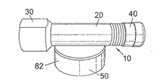
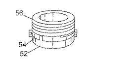
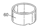
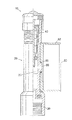
図面の図1〜図5を全体的に参照すると、タイヤ空気圧監視装置10は、内部空間25を密閉する、本発明では細長い本体20と、装置をタイヤバルブに取り付ける取り付け手段30であり、タイヤの内部空間及び本体の内部空間間の気体連通を可能にするようタイヤバルブを開く手段を備えた取り付け手段30と、本体20の内部空間25と気体連通し、装置10を介してタイヤに空気充填を可能にするためのタイヤインフレーションデバイスを収容するバルブ40と、取り付け手段30と気体連通し、装置10を取り付けるタイヤの内圧を受ける密閉圧力チャンバ50であり、本実施形態では電池52の形態の電源、本実施形態では制御回路54として形成した圧力センサ、及びチャンバ50内の圧力を示す信号を発するアンテナ56を収容する密閉圧力チャンバ50と、を備える。電源52、制御回路54、及びアンテナ56の全部が、チャンバ50内の圧力を部分的に受ける。電源52、制御回路54、及びアンテナ56は、中空の円筒形ハウジング60内に取り付ける。
Referring generally to FIGS. 1-5 of the drawings, the tire
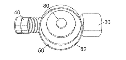
チャンバ50は、第1部分82及び第2部分を有する筐体により形成する。取り付け手段30(タイヤバルブへの取着用)を細長い本体20の一端に形成し、装置のバルブ40(タイヤインフレーションデバイスの収容用)を他端部に形成する。図1及び図2は、チャンバ50を画定する筐体を本体20の長手方向軸に対して横方向にずらして取り付けることを示す。
The
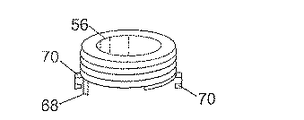
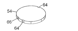
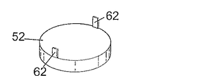
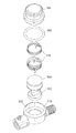
次に図3a〜図3fを参照すると、電池52とアンテナ56との間に制御回路54が挟まれる。電源52、制御回路54、及びアンテナ56は、それぞれが実質的に円盤形である。特に図3aに示すように、電池52には、円盤形電池52の主面の一方から横方向にその縁部に延びる起立部62を設ける。起立部は、電池52の直径方向に対向している。図3bに示すように、制御回路54は、それに対応してその縁部に直径方向に対向した凹部64を有し、これらは起立部62を受け入れて電池52を制御回路54と位置合わせするためのものである。さらに、付加的な凹部66を制御回路54の縁部に設けるが、これは、アンテナ56の主面の一方から離れる方向にその縁部に延びるアンテナ56の位置合わせ起立部68を受け入れるためのものである。これは、アンテナ56を制御回路54に対して位置合わせする役割を果たす。
Next, referring to FIGS. 3 a to 3 f, a
図3cに示すように、本実施形態では、アンテナ56は、アンテナ56の遠位側の端に保持用返し部を有する2つの直径方向に対向したクリップ70も備える。代替的な実施形態では、このようなクリップを3つ以上形成してもよい。図3dに示すように、電池52、制御回路54、及びアンテナ56を互いに接合すると、起立部62及び68が凹部64内に延びる。こうして形成された組立体は、概ね円筒形であり、起立部及びクリップがシリンダの長手方向軸と平行に延びている。クリップ70は、アンテナ70から制御回路54及び電池52の縁部の周りに延び、保持用返し部を電池52の外面(すなわち、制御回路54に隣接する面とは反対側の面)と係合させて組立体を繋ぎ合わせる。電池52、制御回路54、及びアンテナ56はそれぞれ、円筒長手方向軸に対して横断方向に実質的に円形であり、それぞれが実質的に同じ直径を有する。図3eに示すように、続いて、アンテナ56をハウジング60の一方の軸方向端部を越えて露出させた状態で、組立体をハウジング60に入れる。図3fに示すように、ハウジング60及び組立体をチャンバ50に入れ、筐体の上側部分84を第1部分82に接続してシールし、組立体を筐体内に密閉する。
As shown in FIG. 3 c, in this embodiment, the
図4に示すように、チャンバ50を、連通孔80を介して細長い本体の内部空間25に接続する。本実施形態では、孔80の直径は約0.2mmであり、チャンバ50及びその内部の組立体と本体20の内部空間25との間の気体連通を可能にする。連通孔80は、本体の長手方向軸を横切る方向に延びるよう配置する。
As shown in FIG. 4, the
使用時の装置からの空気漏れを防止するために、筐体の第1部分82を本体20に86においてろう付け又ははんだ付け等により取着して両者間に気密シールを形成する。上述のように、筐体のこの第1部分82は、本体から最も遠い端部が開いてもいることでハウジング60及び組立体の容易な収容を可能にする。続いて、筐体の第2部分を組立体の上に載せ、第1部分にシールして気密チャンバを形成し、これに通じる唯一の開口を孔80とする。
In order to prevent air leakage from the device during use, the
図5は、第1実施形態の変形形態を分解図の形態で示す。この変形形態は、第1実施形態と同様であるため、本明細書では相違点のみを説明する。この図は、筐体の上側の第2部分184と、第2部分184が嵌まり込む下側の第1部分182とを示す。電池152、回路154、及びアンテナ156は、この場合も上述のように筐体内に嵌まるが、これらのコンポーネントを筐体に入れる前にこれらを繋ぎ合わせるためのハウジングを設けない点が異なる。Oリング190を筐体の第1部分及び第2部分の表面間に設けて、これらにより形成されるチャンバをシールする。
FIG. 5 shows a variation of the first embodiment in the form of an exploded view. Since this modification is the same as that of the first embodiment, only the differences will be described in this specification. This figure shows a
図4を再度参照すると、装置のコネクタ30をタイヤバルブに螺合して、タイヤバルブと装置10との間にシール接続を形成する。当接部が、タイヤバルブのピンを変位させ、タイヤバルブを開いて本体20の内部空間25とタイヤとの間の気体連通を可能にする。本体20の内部空間25がチャンバ50と気体連通するため、チャンバ50は、このときタイヤの内圧と同じ圧力を受ける。タイヤに空気を充填し、又はタイヤから空気を抜くために、装置を取り外す必要はない。その代わりに、インフレーションデバイスを装置10のバルブ40に接続して、本体20とインフレーションデバイスとの間にシール接続を形成することができる。それから、本体20の内部空間25を介してタイヤへの空気充填を行うことができる。
Referring again to FIG. 4, the
チャンバ50内の組立体は、タイヤ内の圧力を受ける。制御回路54の圧力センサは、チャンバ50内の圧力を検出し、制御回路54は、チャンバ内の圧力が所定の閾値よりも上昇することにより起動されると、チャンバ50内の圧力を示す信号を発するようアンテナ56の制御も行う。この圧力に達するまでは、制御回路は待機モードで起動圧力を待機する。代替的な実施形態では、制御回路は、別個のデバイスからの起動信号により待機モードから起動される。
The assembly in
起動されると、制御回路54は、少なくともチャンバ50内の圧力を示す無線信号を少なくとも1分に1回発するようアンテナ56を制御する。本実施形態では、信号を4秒毎に発する。信号は、高い信号対雑音比を保ちながら約5mの距離範囲に達することができるため、この範囲で明確な信号が得られる。装置の有効範囲は8mであり得る。
When activated, the
信号は別個の受信機により読み取られる。受信機は、携帯型受信機であってもよく、又は車載型であってもよい。信号は、315MHz、434MHz、868MHz、又は915MHzを含む周波数範囲の1つ又は複数で伝送され得る。本実施形態における装置の伝送時のエネルギー消費は、約300nAであるが、起動中のデバイスの総消費は約600nAである。電池52は、リチウムイオン電池、例えばCR1225であり得る。
The signal is read by a separate receiver. The receiver may be a portable receiver or a vehicle-mounted type. The signal may be transmitted in one or more of a frequency range including 315 MHz, 434 MHz, 868 MHz, or 915 MHz. The energy consumption during transmission of the apparatus in this embodiment is about 300 nA, while the total consumption of the active device is about 600 nA. The
いくつかの実施形態では、装置が起動されると、初期圧力信号に加えて個々の装置に固有の識別コードが受信機に送信される。同時に、装置を取り付けたタイヤの識別コードも受信機で受け取ることができるため、タイヤ及び装置の特定の組み合わせを記録することができる。 In some embodiments, when devices are activated, an identification code unique to each device is transmitted to the receiver in addition to the initial pressure signal. At the same time, the identification code of the tire with the device attached can also be received by the receiver, so that a specific combination of tire and device can be recorded.
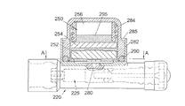
図6及び図7は、本発明の第2実施形態を示す。この場合も、本実施形態は、上述の実施形態と同様であり、先の実施形態との相違点のみを説明する。第2実施形態では、電池、回路、及びアンテナを繋ぎ合わせるためのハウジングの代わりに、電池、回路、及びアンテナを弾性ゲルに埋め込んでから、これを筐体に嵌め込む。図6で見ることができるように、本発明の第2実施形態によれば、上述のように内部空間225を有する本体220が設けられる。同じく上述のように、チャンバ250を筐体により画定し、筐体は、本体220との間に連通孔280を形成して本体220の側面にはんだ付けされる第1部分282と、第1部分282内に嵌まって気密チャンバ250を形成する第2部分284とから形成され、チャンバ250への唯一の空気連通は孔280を介して得られる。Oリング290を第1部分及び第2部分の当接部間に位置決めして、両者間にシールを形成する。第1部分及び第2部分は、一端が閉じた実質的に円筒形の要素として形成し、孔280を第1部品に形成して本体220との連通を可能にする。第2部分の直径を、第2部分と第1部分との間の隙間を最小限にしつつ第2部分が第1部分の開放円筒形範囲内に嵌まることを可能にするのに十分なほど第1部分の直径よりも小さくして、相対的な横方向移動を制限又は防止する。第1部分284の自由端部285を、第2部分に向けて半径方向内方に曲げるか又は圧着して、第2部分を第1部分とシール協働状態に維持する。本実施形態では、電池252、圧力センサを有する回路254、及びアンテナ256をゲル295で包被する。図6は、第2実施形態のセンサデバイスを、図7に示すような断面と共に示す。図7は、筐体の第1部分及び筐体の第2部分が概ね円筒形であり、第2部分が第1部分内に半径方向に嵌まっていることを示す。さらに、電池252、回路254、及びアンテナ256を包被する包被ゲルも概ね円筒形である。
6 and 7 show a second embodiment of the present invention. Also in this case, the present embodiment is the same as the above-described embodiment, and only differences from the previous embodiment will be described. In the second embodiment, instead of the housing for connecting the battery, the circuit, and the antenna, the battery, the circuit, and the antenna are embedded in an elastic gel, and then inserted into the housing. As can be seen in FIG. 6, according to the second embodiment of the present invention, a
図7で見ることができるように、包被ゲル295の下端部(すなわち、筐体の第1部分282内で最も遠い端部)には、半径方向に延びる6つの突出部があり、ゲル295のこれらの突出部が第1部分282の平坦な底面に載る。これらの突出部は、本体225内の圧力がこれらの間からチャンバ250入ることを可能にする。さらに、図7に示すように、包被ゲル295の円筒形側面に沿って、規則的に軸方向に延びる(すなわち、筐体280の円筒軸と平行な)窪み297を設ける。これらは、本体220から筐体の第2部分284の側面を上る空気の連通を可能にして、本体の内部空間225と回路254の圧力センサとを連通させる。
As can be seen in FIG. 7, at the lower end of the encapsulating gel 295 (ie, the furthest end within the
第2実施形態では、回路254は、図示されていない隆起した中空の円筒形ハウジングを備え、ゲル295は、この円筒形ハウジングの外側面に沿って延びるが頂部までは達さず、頂部は回路254の圧力センサをチャンバ内の空気圧に直接さらすよう開いている。円筒形ハウジングは、制御回路254上の圧力センサを包囲し、ゲル295が圧力センサを覆わないことを確実にすることにより、圧力センサがチャンバ250内の空気圧を検出できるようにする。
In the second embodiment, the
包被ゲルの製造に用いる金型を用いることができる。金型は、概ね円筒形の凹部を含む。凹部の底に、複数(本実施形態では6つ)の窪みを設ける。さらに、凹部の円筒縁部の周りに、複数の軸方向に延びる窪みを設ける。凹部は完全な円筒形ではなく、その閉鎖端に向けてわずかにテーパ状にすることで、ゲルを金型に入れて硬化させてからのゲルの取り出しを容易にする。 A mold used for the production of the covering gel can be used. The mold includes a generally cylindrical recess. A plurality (six in this embodiment) of depressions are provided at the bottom of the recess. Further, a plurality of axially extending depressions are provided around the cylindrical edge of the recess. The recess is not completely cylindrical but is tapered slightly toward its closed end to facilitate removal of the gel after it has been cured in the mold.
本実施形態では、ゲルを続いて液体形態で流し込む。ゲルは、電池252及び回路254を覆ってアンテナ256を部分的に覆うようになるまで流し込む。ゲル295が固化すると、圧力センサがチャンバ内の空気に曝されたまま、アンテナ256、回路254、及び電池252がゲル295により少なくとも部分的に包被され保護されるよう、ゲルの高さをハウジングの頂部よりも下で止める。
In this embodiment, the gel is subsequently poured in liquid form. The gel is poured until it covers the
本実施形態では、Oリング290を、第2部分284の自由円筒端部のフランジの周りに配置する。凹部に加えて、金型のテーパ部は、ゲル295と第2部分284との間で第2部分294の自由端部の領域に隙間を作り、これが、本体220の内部空間225とチャンバ250との均圧化を可能にする付加的な空隙を提供する。
In this embodiment, the O-
使用中、第2実施形態によるデバイスは、図1〜図5を参照して上述したのと同様に機能する。 In use, the device according to the second embodiment functions in the same manner as described above with reference to FIGS.
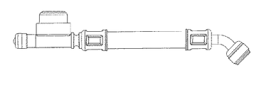
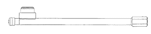
さらに他の実施形態を図8及び図9に示す。装置の動作は上述と同様である。しかしながら、図8に示す実施形態は、装置のコネクタとチャンバとの間に嵌まる可撓性延長部を本体の一部として備え、内部空間はこの可撓部の長さに沿って延びる。図9に示す実施形態も同様であるが、細長い本体をチャンバとコネクタとの間で延長させた点が異なる。 Yet another embodiment is shown in FIGS. The operation of the apparatus is the same as described above. However, the embodiment shown in FIG. 8 includes a flexible extension as part of the body that fits between the connector of the device and the chamber, and the interior space extends along the length of the flexible portion. The embodiment shown in FIG. 9 is similar, except that an elongated body is extended between the chamber and the connector.
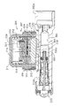
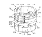
図10〜図13は、本発明のさらに別の実施形態を示す。本実施形態の1つ又は複数の特徴は、上述の実施形態の特徴と置換することができる。本実施形態に関して説明する多くの特徴は、対応する上述の特徴と同一又は同様であり得る。図10において、301は、自動車のタイヤの内圧を(及び場合によっては、温度及び/又は他のパラメータも)監視するデバイス/タイヤ内圧監視装置の全体を示す。
10-13 illustrate yet another embodiment of the present invention. One or more features of this embodiment may be replaced with features of the above-described embodiments. Many features described with respect to this embodiment may be the same as or similar to the corresponding features described above. In FIG. 10,
例として示す実施形態では、上記デバイスは、例えば金属材料でできた延長管/本体302を備え、延長管302の第1端部302aは、タイヤの空気充填弁の口にシール結合するよう構成し、取り付け手段を備えることができ、延長管302の他端部302bには、バルブを含み得る取り外し可能なシーリングキャップ303を設けた。
In an exemplary embodiment, the device comprises an extension tube /
軸方向導管/内部空間304を、延長管302内に画定し、使用時にデバイス301が関連するタイヤの内部と気体連通させる。
An axial conduit /
延長管302の中間部は、横方向突出部305を有し、ここに導管304と連通する横断通路/連通孔306が形成される。
The intermediate portion of the
突出部305の周りで、全体として307で示す支持ケーシング/筐体を、例えば溶接により延長管302に横から接続する。例として示す実施形態では、上記支持ケーシングは、例えば金属材料でできた本質的にカップ形の部材/第1部分308を備え、これは下壁に開口308aを有し、開口308a内に延長管302の突出部305が延びてシールされる。本質的にグラスを上下反転させた形状の本体/第2部分309を、カップ形本体308に結合する。例として示す実施形態では、本体308の口を本体309に向けて曲げ戻す。
Around the
全体として311で示す組立体を内部に装着する領域又はチャンバ310を、本体308と309との間に画定し、本体308及び309を組み合わせて支持ケーシング307を形成する。
A region or
以下の本文から明確となるように、組立体311は、回路担持板/制御回路313を有するアンテナ312と電圧供給電池314とを含む。
As will become clear from the text below, the
アンテナ312、回路担持板313、及び電池314は、鋳造により、ゲル等の電気絶縁シール材料、場合によっては制振材料塊315を少なくとも部分的に組み込むことが得策である。
The
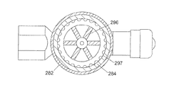
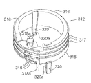
図11〜図13を参照すると、寸法が小さいためここではマイクロアンテナとも称するアンテナ312は、電気絶縁材料でできた環状部材316を含む支持構造体を備え、これを回路担持板313に結合する。
Referring to FIGS. 11 to 13, the
環状部材316の外側面は、螺旋溝317を有し、導電材料、特に錫めっき銅でできたワイヤ318をここに巻き付ける。
The outer surface of the
導電ワイヤ318は、アンテナの放射部材を形成し、ほぼ半径方向に曲がってホルダ319により係合保持される第1端部318a(図11及び図12)を有し、ホルダ319は、環状支持部材316と一体形成されることが得策である。図11及び図12に318bで示す導電ワイヤ318の他端部は、環状部材316の軸と少なくともほぼ平行な方向に曲がり、回路担持板313(図12)に事前配置した対応の貫通孔を貫通し、回路担持板313に例えば溶接により締結される。
The
底部において、環状支持部材316は一対の弾性ラグ320を有し、これらの各遠位端部に保持歯320a(図11)を設ける。上記ラグ320は、回路担持板313における対応の周辺切欠部13a(図12)に係合し、各歯320aを上記板の下に係合させる。
At the bottom, the
図13でより明確に見ることができるように、回路担持板313の上面は、321で示す電気式圧力変換器を担持し、場合によっては温度センサも担持する。上記板313は、全体として322で示す複数のさらに他の電気/電子コンポーネントも有する。
As can be seen more clearly in FIG. 13, the upper surface of the
管状保護部材323を、板313の上面で圧力変換器321(図10、図11、及び図13)の周りに配置し、例えば接着結合により締結するが、その機能は本明細書中で後述する。
A tubular
電池314の接続用の導電板324も、板313に接続する。
A
図12及び図13に示すように、アンテナ312を回路担持板313及び電池314と組み立てた後、この組立体を金型に入れ、そこに電気絶縁シール材料を鋳込んで、図10に315で示す材料塊を形成することが得策である。この作業の実行中、管状部材323は、鋳造材料が圧力変換器321及び場合によっては関連の温度センサに組み込まれることも防止する。
As shown in FIGS. 12 and 13, after the
図10で見ることができるように、電気絶縁材料塊315は、アンテナ312の下側部分、回路担持板、及び関連コンポーネントを組み込むが、言及したように、圧力変換器321及び少なくとも電池314の一部は組み込まない。こうして形成した組立体311は、個別に扱うことができ、支持ケーシング307(図10)内に画定した領域又はチャンバ310内に容易に装着することができる。
As can be seen in FIG. 10, the electrically insulating
組立状態(図10)では、領域310のうち圧力変換器321の上方に位置する部分を、延長管302の通路306と、したがって上記管内に形成した導管304と気体連通させるような構成になる。結果として、使用中に変換器321は、監視デバイス301が動作的に関連するタイヤ内圧の値を示す電気信号を発生することができる。この信号は、回路板313が担持したデバイス322により処理され、アンテナ312により車載の受信・処理・制御装置に送られる。
In the assembled state (FIG. 10), the
弾性リングシール325(図10)を、本体309と本体308の側壁との間で半径方向に圧縮するように本体309の外側環状凹部326内に配置する。上記弾性リング325は、通路6が圧力変換器及び場合によっては温度変換器が存在しない領域と気体連通することを防止する。
A resilient ring seal 325 (FIG. 10) is disposed in the outer
環状支持部材316は、所定の誘電率を有するプラスチック材料を成形することにより個別に形成することが得策である。一括成形という解決手段は、絶縁管の切断により環状支持部材を得るのと比較して好ましいが、その理由は、寸法精度及び再現性の改善が確保されるからである。
It is advisable to form the
環状支持部材316の溝に導電ワイヤ318を巻き付けることで、自由螺旋ワイヤを用いる解決手段と比較してアンテナの特徴部の寸法安定性の改善及びばらつきの低減が保証される。さらに、デバイスが高度な機械的応力を受けた場合でも、その動作寿命にわたって導電ワイヤ318の寸法安定性の改善が確保される。
Wrapping the
本発明は、単に例として本明細書で説明したものであり、本発明の範囲及び趣旨から逸脱せずに種々の変更、省略、及び追加を行うことができる。本発明において、文脈により別段の要求がない限り、「備える」等の用語は網羅的ではなく包括的な意味で、すなわち「非限定的に含む」という意味で解釈されるものとする。 The present invention has been described herein by way of example only, and various modifications, omissions, and additions can be made without departing from the scope and spirit of the invention. In the present invention, unless otherwise required by the context, terms such as “comprising” are to be interpreted in an inclusive rather than exhaustive sense, ie “including but not limited to”.
Claims (17)
密閉内部空間を備えた本体と、
該装置をタイヤバルブに取り付ける取り付け手段であり、前記タイヤの内部空間及び前記本体の前記内部空間間の気体連通を可能にするよう前記タイヤバルブを開く手段を備えた取り付け手段と、
前記本体の前記内部空間と気体連通し、該装置を介した前記タイヤへの空気充填を可能にするためのタイヤインフレーションデバイスを収容するバルブと、
前記取り付け手段と気体連通し、該装置を取り付けた前記タイヤの内圧を受ける密閉圧力チャンバであり、少なくとも、
電源、
圧力センサ、及び
前記チャンバ内の圧力を示す信号を発するアンテナ、
を収納する密閉圧力チャンバと、
を備え、前記電源、前記圧力センサ、及び前記アンテナを結合材料で少なくとも部分的に包被して、前記圧力チャンバ内でそれらの相対位置を維持したことを特徴とするタイヤ空気圧監視装置。 A tire pressure monitoring device,
A body with a sealed interior space;
Mounting means for attaching the device to a tire valve, the mounting means comprising means for opening the tire valve to allow gas communication between the internal space of the tire and the internal space of the body;
A valve containing a tire inflation device in gas communication with the internal space of the body and allowing the tire to be filled with air through the device;
A sealed pressure chamber in gas communication with the attachment means and receiving the internal pressure of the tire to which the apparatus is attached,
Power supply,
A pressure sensor, and an antenna that emits a signal indicating the pressure in the chamber;
A sealed pressure chamber containing
A tire pressure monitoring device comprising: a power supply, the pressure sensor, and the antenna at least partially encased with a bonding material to maintain their relative positions in the pressure chamber.
Applications Claiming Priority (4)
| Application Number | Priority Date | Filing Date | Title |
|---|---|---|---|
| ITTO2010A001009 | 2010-12-17 | ||
| ITTO2010A001009A IT1403407B1 (en) | 2010-12-17 | 2010-12-17 | MICROANTENNA AND TRANSMITTER DEVICE FOR THE MONITORING OF THE PRESSURE OF A TIRE OF A MOTOR VEHICLE |
| ITTO2011A000093 | 2011-02-04 | ||
| ITTO2011A000093A IT1404045B1 (en) | 2011-02-04 | 2011-02-04 | TIRE PRESSURE CONTROL SYSTEM |
Publications (1)
| Publication Number | Publication Date |
|---|---|
| JP2012144246A true JP2012144246A (en) | 2012-08-02 |
Family
ID=45217426
Family Applications (1)
| Application Number | Title | Priority Date | Filing Date |
|---|---|---|---|
| JP2011275529A Pending JP2012144246A (en) | 2010-12-17 | 2011-12-16 | Tire pressure monitoring system |
Country Status (2)
| Country | Link |
|---|---|
| EP (1) | EP2465712B1 (en) |
| JP (1) | JP2012144246A (en) |
Cited By (2)
| Publication number | Priority date | Publication date | Assignee | Title |
|---|---|---|---|---|
| JP2017088171A (en) * | 2015-11-13 | 2017-05-25 | ハンコック タイヤ カンパニー リミテッド | Tire sensor installation structure provided with sensor patch and manufacturing method for same |
| CN106739855A (en) * | 2016-12-03 | 2017-05-31 | 东莞市皓奇企业管理服务有限公司 | How to use the intelligent network anti-run tire device |
Families Citing this family (16)
| Publication number | Priority date | Publication date | Assignee | Title |
|---|---|---|---|---|
| CN103264621A (en) * | 2013-06-03 | 2013-08-28 | 南京来阳电子科技有限公司 | External non-air-faucet contact tire pressure monitoring device |
| DE102014205923B4 (en) * | 2014-03-31 | 2023-06-07 | Aktiebolaget Skf | Module for detecting a physical quantity of a gaseous medium |
| ES2930234T3 (en) * | 2014-09-17 | 2022-12-09 | Ste Ind S R L | Device and transmission method for wireless transmission of measured parameters |
| DE102015102324A1 (en) * | 2015-02-18 | 2016-08-18 | Huf Hülsbeck & Fürst Gmbh & Co. Kg | Sensor for a tire pressure monitoring system |
| DE102015120141A1 (en) * | 2015-11-20 | 2017-05-24 | Bpw Bergische Achsen Kg | Tire filling device for a vehicle wheel |
| CN105437884A (en) * | 2015-12-22 | 2016-03-30 | 广西玲珑轮胎有限公司 | Intelligent all-steel radial tire |
| US11198335B2 (en) | 2016-01-21 | 2021-12-14 | Dana Heavy Vehicle Systems Group, Llc | Integrated-sensor valve apparatus |
| BR112021015546A2 (en) * | 2019-02-14 | 2021-10-05 | Meggitt Sa | MOUNTING A SENSOR TO DETERMINE A PHYSICAL PROPERTY OF A VEHICLE |
| EP3938642B1 (en) | 2019-03-15 | 2024-06-12 | Donaldson Company, Inc. | Filter restriction indicator |
| CN110281709B (en) * | 2019-06-12 | 2024-01-16 | 深圳市永奥图电子有限公司 | External tire pressure monitor |
| FR3108403B1 (en) * | 2020-03-22 | 2022-04-08 | Safran | Tire pressure measuring device |
| WO2023123831A1 (en) * | 2021-12-30 | 2023-07-06 | 万通智控科技股份有限公司 | Threaded fixing structure |
| CN217158622U (en) * | 2022-07-06 | 2022-08-09 | 万通智控科技股份有限公司 | Spiral antenna assembly and tire pressure sensor |
| WO2024223464A1 (en) | 2023-04-24 | 2024-10-31 | STE Industries s.r.l. | Pressure monitoring device for a pressurized environment, particularly for a tire |
| WO2024223467A1 (en) | 2023-04-24 | 2024-10-31 | STE Industries s.r.l. | Pressure monitoring device for a pressurized environment, particularly for a tire |
| US12491740B2 (en) * | 2023-05-16 | 2025-12-09 | Hamaton Automotive Technology Co., Ltd. | External TPMS sensor for heavy-duty trucks |
Citations (13)
| Publication number | Priority date | Publication date | Assignee | Title |
|---|---|---|---|---|
| JPS61241206A (en) * | 1985-02-22 | 1986-10-27 | レオナ−ド エフ.バ−ジ | Tire alarm device |
| JPH03207103A (en) * | 1990-01-09 | 1991-09-10 | Toyo Commun Equip Co Ltd | Method of forming spiral conductor pattern on peripheral surface of column body and column body antenna |
| JPH04106440A (en) * | 1990-08-28 | 1992-04-08 | Toyota Autom Loom Works Ltd | Pressure sensor |
| JPH1038730A (en) * | 1996-07-25 | 1998-02-13 | Matsushita Electric Works Ltd | Pressure sensor and pressure detector using the same |
| JP2000118214A (en) * | 1998-10-09 | 2000-04-25 | Kyowa Electron Instr Co Ltd | Tire pressure monitoring device |
| JP2000142043A (en) * | 1998-11-09 | 2000-05-23 | Toyota Motor Corp | Tire pressure warning device |
| JP2003118336A (en) * | 2001-06-28 | 2003-04-23 | Pacific Ind Co Ltd | Transmitter for tire condition monitoring device and manufacturing method therefor |
| JP2004326158A (en) * | 2003-04-21 | 2004-11-18 | Yokohama Rubber Co Ltd:The | Sensor device for tire mounting, and sensor-mounted tire |
| US20060173648A1 (en) * | 2005-02-01 | 2006-08-03 | Hung-Sen Chang | Wireless tire-pressure monitor |
| JP2006329883A (en) * | 2005-05-27 | 2006-12-07 | Hitachi Ltd | Gas pressure detector |
| US20070193349A1 (en) * | 2006-02-13 | 2007-08-23 | Steven Petrucelli | Tire pressure gauge |
| JP2010501393A (en) * | 2006-08-21 | 2010-01-21 | ローベルト ボツシユ ゲゼルシヤフト ミツト ベシユレンクテル ハフツング | Tire sensor module and manufacturing method thereof |
| JP2010210612A (en) * | 2009-03-06 | 2010-09-24 | Sung Jung Minute Industry Co Ltd | Tire pressure measuring device |
Family Cites Families (5)
| Publication number | Priority date | Publication date | Assignee | Title |
|---|---|---|---|---|
| US5783992A (en) * | 1996-07-22 | 1998-07-21 | Delco Electronics Corp. | Time based low tire pressure warning sensor |
| US6856245B2 (en) * | 2003-07-09 | 2005-02-15 | Julian Smith | Tire condition monitoring system with improved sensor means |
| EP1942018A1 (en) * | 2007-01-02 | 2008-07-09 | Josn Electronic Co., Ltd. | Connecting assembly for a wireless tire pressure monitoring apparatus |
| US7656281B2 (en) * | 2007-05-16 | 2010-02-02 | Joe Huayue Zhou | External air-flow-through valve stem mounted tire pressure monitoring apparatus |
| IT1395655B1 (en) * | 2009-08-04 | 2012-10-16 | Eltek Spa | MONITORING DEVICE FOR A WHEEL OF A VEHICLE |
-
2011
- 2011-12-16 EP EP11194091.2A patent/EP2465712B1/en active Active
- 2011-12-16 JP JP2011275529A patent/JP2012144246A/en active Pending
Patent Citations (13)
| Publication number | Priority date | Publication date | Assignee | Title |
|---|---|---|---|---|
| JPS61241206A (en) * | 1985-02-22 | 1986-10-27 | レオナ−ド エフ.バ−ジ | Tire alarm device |
| JPH03207103A (en) * | 1990-01-09 | 1991-09-10 | Toyo Commun Equip Co Ltd | Method of forming spiral conductor pattern on peripheral surface of column body and column body antenna |
| JPH04106440A (en) * | 1990-08-28 | 1992-04-08 | Toyota Autom Loom Works Ltd | Pressure sensor |
| JPH1038730A (en) * | 1996-07-25 | 1998-02-13 | Matsushita Electric Works Ltd | Pressure sensor and pressure detector using the same |
| JP2000118214A (en) * | 1998-10-09 | 2000-04-25 | Kyowa Electron Instr Co Ltd | Tire pressure monitoring device |
| JP2000142043A (en) * | 1998-11-09 | 2000-05-23 | Toyota Motor Corp | Tire pressure warning device |
| JP2003118336A (en) * | 2001-06-28 | 2003-04-23 | Pacific Ind Co Ltd | Transmitter for tire condition monitoring device and manufacturing method therefor |
| JP2004326158A (en) * | 2003-04-21 | 2004-11-18 | Yokohama Rubber Co Ltd:The | Sensor device for tire mounting, and sensor-mounted tire |
| US20060173648A1 (en) * | 2005-02-01 | 2006-08-03 | Hung-Sen Chang | Wireless tire-pressure monitor |
| JP2006329883A (en) * | 2005-05-27 | 2006-12-07 | Hitachi Ltd | Gas pressure detector |
| US20070193349A1 (en) * | 2006-02-13 | 2007-08-23 | Steven Petrucelli | Tire pressure gauge |
| JP2010501393A (en) * | 2006-08-21 | 2010-01-21 | ローベルト ボツシユ ゲゼルシヤフト ミツト ベシユレンクテル ハフツング | Tire sensor module and manufacturing method thereof |
| JP2010210612A (en) * | 2009-03-06 | 2010-09-24 | Sung Jung Minute Industry Co Ltd | Tire pressure measuring device |
Cited By (2)
| Publication number | Priority date | Publication date | Assignee | Title |
|---|---|---|---|---|
| JP2017088171A (en) * | 2015-11-13 | 2017-05-25 | ハンコック タイヤ カンパニー リミテッド | Tire sensor installation structure provided with sensor patch and manufacturing method for same |
| CN106739855A (en) * | 2016-12-03 | 2017-05-31 | 东莞市皓奇企业管理服务有限公司 | How to use the intelligent network anti-run tire device |
Also Published As
| Publication number | Publication date |
|---|---|
| EP2465712B1 (en) | 2020-10-21 |
| EP2465712A1 (en) | 2012-06-20 |
| EP2465712A8 (en) | 2012-08-15 |
Similar Documents
| Publication | Publication Date | Title |
|---|---|---|
| JP2012144246A (en) | Tire pressure monitoring system | |
| US6885291B1 (en) | Mouting transponders and antennas in pneumatic tires | |
| US6899153B1 (en) | Mounting transponders and antennas in pneumatic tires | |
| US5731754A (en) | Transponder and sensor apparatus for sensing and transmitting vehicle tire parameter data | |
| US6546982B1 (en) | Mounting transponders in pneumatic tires | |
| EP3122575B1 (en) | A tyre sensor device | |
| US4137520A (en) | Tire pressure indicator system | |
| JPH08178784A (en) | Tire air pressure alarm | |
| US20100164705A1 (en) | Self-powered sensor system for monitoring tire pressure | |
| KR20130070590A (en) | Electric machine component temperature monitoring | |
| JP2005162192A (en) | Unifying method of tire discrimination information to vehicle information system | |
| EP1800912A1 (en) | Tire information transmission device, tire information acquisition system, and tire/wheel assembly | |
| WO2008043184A1 (en) | Methods and apparatus for mounting a sensor inside a wheel cavity | |
| CN1976821A (en) | Tyre pressure monitoring sensor | |
| TW200925006A (en) | Automobile control system and valve | |
| WO2005035278A2 (en) | System and method for providing tire electronics mounting patches | |
| WO2001036221A1 (en) | Mounting transponders and antennas in pneumatic tires | |
| JP2023015370A (en) | sensor module | |
| WO2013013325A1 (en) | Tire-tube pressure monitoring patch | |
| CN113167674A (en) | Enclosed pressure sensor | |
| WO2001036220A1 (en) | Mounting transponders and antennas in pneumatic tires | |
| JP2005186658A (en) | Tire valve equipped with tire air pressure sensing means and tire air pressure sensing device using the valve | |
| US20070028699A1 (en) | Pressure sensor | |
| WO2012080991A1 (en) | Microantenna and transmitter device for monitoring the pressure of a tire of a motor-vehicle | |
| US11787243B2 (en) | Electronic unit for measuring operating parameters of a vehicle wheel and suitable for being positioned on the inner surface of a tread of a tire |
Legal Events
| Date | Code | Title | Description |
|---|---|---|---|
| A621 | Written request for application examination |
Free format text: JAPANESE INTERMEDIATE CODE: A621 Effective date: 20141127 |
|
| A977 | Report on retrieval |
Free format text: JAPANESE INTERMEDIATE CODE: A971007 Effective date: 20160126 |
|
| A131 | Notification of reasons for refusal |
Free format text: JAPANESE INTERMEDIATE CODE: A131 Effective date: 20160202 |
|
| A521 | Written amendment |
Free format text: JAPANESE INTERMEDIATE CODE: A523 Effective date: 20160428 |
|
| A02 | Decision of refusal |
Free format text: JAPANESE INTERMEDIATE CODE: A02 Effective date: 20160920 |