EP1942018A1 - Connecting assembly for a wireless tire pressure monitoring apparatus - Google Patents
Connecting assembly for a wireless tire pressure monitoring apparatus Download PDFInfo
- Publication number
- EP1942018A1 EP1942018A1 EP07000008A EP07000008A EP1942018A1 EP 1942018 A1 EP1942018 A1 EP 1942018A1 EP 07000008 A EP07000008 A EP 07000008A EP 07000008 A EP07000008 A EP 07000008A EP 1942018 A1 EP1942018 A1 EP 1942018A1
- Authority
- EP
- European Patent Office
- Prior art keywords
- tube
- tire pressure
- adapter
- connecting assembly
- sleeve portion
- Prior art date
- Legal status (The legal status is an assumption and is not a legal conclusion. Google has not performed a legal analysis and makes no representation as to the accuracy of the status listed.)
- Withdrawn
Links
Images


Classifications
-
- B—PERFORMING OPERATIONS; TRANSPORTING
- B60—VEHICLES IN GENERAL
- B60C—VEHICLE TYRES; TYRE INFLATION; TYRE CHANGING; CONNECTING VALVES TO INFLATABLE ELASTIC BODIES IN GENERAL; DEVICES OR ARRANGEMENTS RELATED TO TYRES
- B60C23/00—Devices for measuring, signalling, controlling, or distributing tyre pressure or temperature, specially adapted for mounting on vehicles; Arrangement of tyre inflating devices on vehicles, e.g. of pumps or of tanks; Tyre cooling arrangements
- B60C23/02—Signalling devices actuated by tyre pressure
- B60C23/04—Signalling devices actuated by tyre pressure mounted on the wheel or tyre
- B60C23/0408—Signalling devices actuated by tyre pressure mounted on the wheel or tyre transmitting the signals by non-mechanical means from the wheel or tyre to a vehicle body mounted receiver
-
- B—PERFORMING OPERATIONS; TRANSPORTING
- B60—VEHICLES IN GENERAL
- B60C—VEHICLE TYRES; TYRE INFLATION; TYRE CHANGING; CONNECTING VALVES TO INFLATABLE ELASTIC BODIES IN GENERAL; DEVICES OR ARRANGEMENTS RELATED TO TYRES
- B60C23/00—Devices for measuring, signalling, controlling, or distributing tyre pressure or temperature, specially adapted for mounting on vehicles; Arrangement of tyre inflating devices on vehicles, e.g. of pumps or of tanks; Tyre cooling arrangements
- B60C23/02—Signalling devices actuated by tyre pressure
- B60C23/04—Signalling devices actuated by tyre pressure mounted on the wheel or tyre
- B60C23/0491—Constructional details of means for attaching the control device
- B60C23/0496—Valve stem attachments positioned outside of the tyre chamber
Definitions
- the invention relates to a connecting assembly for a wireless tire pressure monitoring apparatus, and more particularly, to an apparatus that is suitable for installation on the internal tires of heavy vehicles without affecting the tire inflation operation.
- the tires of all kinds of vehicles have to be kept at a normal tire pressure. If the tire has a lower tire pressure (than 28 psi) or runs at a high temperature, the driving safety will be affected. After some time of driving, exposure to the sunlight or the fall of temperature at night, the tire may leak to some extent and the tire pressure will fall down under a normal pressure of 28 psi. It brings a potential danger for the driving safety. Particularly, if one tire of a high speeding vehicle breaks up due to the bad airtightness of the tire valve leading to the insufficient tire pressure, the result is very destructive.
- a conventional tire pressure monitoring apparatus 10 includes an adapter 11 at the front end thereof that is screwed on an inflation valve 21 at the external side of the tire 20.
- a pressure-detecting element 12 is disposed within the tire pressure detector 10 for determining the tire pressure value of the tire 20. Meanwhile, a signal is transmitted to a receiving and displaying apparatus (not shown) within the vehicle.
- a lock nut 22 is installed for preventing the tire pressure detector 10 from unauthorized removal by the act of stealing.
- the above-mentioned tire pressure detector 10 has no problem in installing at a normal vehicle and applying thereto.
- some consumers have provided a few feedbacks.
- the heavy vehicles like trucks or tourist coaches have a left and a right tire 20 at the front while the left and right tires at the rear each has a combination of an internal and an external tire 20a, 20b both of which are mounted on a drive shaft 23. Accordingly, the installation of the front tire 20 and the external tire 20b has no problem.
- the internal tire 20a will be blocked by the external tire 20b. Passing through the hole 24 of the external wheel rim is therefore required for the inflation. In this way, the inflation of the internal tire 20a via the inflation valve (not shown) is possible.
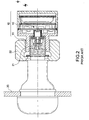
- the tire pressure detector 10 As shown in FIG. 2 , is installed on the inflation valve at the internal side, the tire pressure detector 10 has to be removed first prior to the inflation. Nevertheless, the removal is much inconvenient since the tire pressure detector 10 is disposed next to the external tire 20b and therefore only little free room is available. In addition, it brings also difficulties to re-screw the tire pressure detector 10 in position when each inflation operation is completed. To carry out the above-mentioned operation within such a narrow space between the internal and external tires does consume much time and cost. This doesn't fulfill the requirement of the economic benefit.
- a connecting assembly for a wireless tire pressure monitoring apparatus that is formed in a branch joint with a first tube, a second tube, and a third tube.
- a connecting assembly for a wireless tire pressure monitoring apparatus in accordance with the invention includes:
- a connecting assembly 70 in accordance with the invention includes a main body 30, an adapter 50, and an air nozzle 60.
- the main body 30 is formed in a branch joint with a first tube 31, a second tube 32, and a third tube 33.
- the first tube 31 and the third tube 33 are communicated with each other in axial direction while the second tube 32 is perpendicular to the first tube 31 and the third tube 33, thereby creating a T-form.
- a penetration needle 40 with a first vent hole 41 is positioned within the first tube 31.
- the external wall of the second tube 32 is fitted with a first threaded section 321.
- a second threaded section 331 is formed on the internal wall of the third tube 33.
- the external wall of the third tube 33 is provided with a third threaded section 332 having the same diameter as an inflation valve 21.
- the adapter 50 is attached to an end port of the first tube 31 and mounted on the external wall of the penetration needle 40.
- the internal wall of the adapter 50 is provided with a fourth thread 51 screwed to the inflation valve 21.
- the adapter 50 enables the connection between the main body 30 and the inflation valve 21 for establishing an airway. Therefore, the main body 30 can be integrally formed (not shown). Alternatively, the adapter 50 can be individually formed and then attached to the main body 30. These are applicable embodiments, but should not restricted thereto. It is preferable that the adapter 50 is pivotally attached to the main body 30. In other words, the adapter 50 creates a detachable connection to the main body 30.
- the adapter 50 includes a sleeve portion 53 with a smaller diameter at a contact end to the first tube 31.
- the middle part of the penetration needle 40 is provided with a flange 42 corresponding to the sleeve portion 53.
- the flange 42 is used to position the sleeve portion 53 without clamping it.
- a part of the penetration needle 40 is fixed within the first tube 31 such that the sleeve portion 53 of the adapter 50 is mounted between the penetration needle 40 and the first tube 31.
- a smooth connection between the main body 30 of a T-shaped connecting assembly 80 and the inflation valve 21 is established only by turning the adapter 50 without turning the main body 30 when the adapter 50 connects the main body 30 to the inflation valve 21.
- the internal section of the adapter 50 is formed into a polygonal body such as into hexagonal body. Accordingly, the adapter 50 can be conveniently screwed with a screwing tool to the inflation valve 21.
- an air nozzle 60 having the same structure as the conventional inflation valve 21 is screwed into the third tube 33 such that the third tube 33 is normally maintained in a closed position.
- the air nozzle 60 includes a hollow sleeve portion 61 screwed into the third tube 33, thereby forming a second vent hole 62.
- An actuating pin 63 axially passing through the second vent hole 62 is mounted on the sleeve portion 61.
- a spring 64 is mounted on the sleeve portion 61.
- the tail of the sleeve portion 61 is formed into a tapering air inlet 65.
- the tail of the actuating pin 63 includes a compression cover 66 for opening and closing the air inlet 65. In this way, the actuating pin 63 is shifted outwards in the ordinary state by the tension of the spring 64 such that the air inlet 65 of the second vent hole 62 is closed by the compression cover 66. As a result, the escape of the air pressure of the tire from the third tube 33 can be avoided.
- a washer 44 is disposed on a contact surface between the penetration needle 40 and the first tube 31.
- a sealing ring 43 is disposed at an internal side of the flange 42 of the penetration needle 40.
- the penetration needle 40 creates a threaded connection to the first tube 313 and lies against the washer 44.
- the penetration needle 40 is forced to push against a valve stem 211 of the inflation valve 21 when the adapter 50 is screwed to the inflation valve 21.
- the air pressure within the tire 20 can flow through the first tube 31 into the main body 30.
- a tire pressure detector 10 mounted on the second tube 32 can perform the tire pressure detection operation.
- the connecting assembly 70 in accordance with the invention may ensure a reliable connection of the tire pressure detector 10 to the second tube 32, thereby creating a free air passage.
- the tire 20 can be directly inflated via the third tube 33 without pulling the tire pressure detector 10 out of the second tube 32.
- the third tube 33 has the same function as the inflation valve 21.
- the actuating pin 63 In fitting an inflating adapter (not shown) into the third tube 33, the actuating pin 63 is retracted inwards such that the compression cover 66 is removed from the air inlet 65 of the second vent hole 62 for a smooth entrance of the inflating air. Thereafter, the inflating air passes through the first vent hole 41 of the penetration needle 40 of the first tube 31 so that the inflation via the inflation valve 21 can be done. After the inflation is completed, the actuating pin 63 is returned by the tension of the spring 64 to the closed position (see FIG. 5 ) where the compression cover 66 lies against the air inlet 65 of the second vent hole 62.
- the invention employs the connecting assembly 70 so that it is not necessary to pull out the tire pressure detector 10 when the tire is inflated. It proves to be practical and convenient and effectively resolves the conventional problems.
- the tire pressure detector 10 is not the object of the invention so that its structure and principle are not detailed hereinafter.
- the tire pressure detector 10 in accordance with the invention relates to the patented product of U.S. Pat. No. 6,993,962 . Other tire pressure detectors 10 are also applicable.
Abstract
A connecting assembly for a wireless tire pressure monitoring apparatus having a main body (30) formed to be a branch joint with a first tube (31), a second tube (32) and a third tube (33), a penetration needle (40) with a first vent hole (41) being positioned at the port of the first tube (31); an adapter (50) attached to an end port of the first tube (31); a actuating pin disposed within the first tube (31) and the third tube (33); and the air nozzle (60) screwed in the third tube (33), the middle part of the sleeve portion (53) having an second vent hole (62) in the axial direction. When the first tube (31) is mounted on the inflation valve (21), the air pressure within the tire (20) will pass through the first tube (31). In this way, the tire pressure detector joined to the second tube (32) can detect the tire pressure value at any time. It is not necessary to remove the tire pressure detector (10) on the second tube (32) for the inflation operation. Instead, the inflation of the tire can be done via the third tube (33), thereby facilitating the inflation of the internal tires to a great extent.
Description
- The invention relates to a connecting assembly for a wireless tire pressure monitoring apparatus, and more particularly, to an apparatus that is suitable for installation on the internal tires of heavy vehicles without affecting the tire inflation operation.
- The tires of all kinds of vehicles have to be kept at a normal tire pressure. If the tire has a lower tire pressure (than 28 psi) or runs at a high temperature, the driving safety will be affected. After some time of driving, exposure to the sunlight or the fall of temperature at night, the tire may leak to some extent and the tire pressure will fall down under a normal pressure of 28 psi. It brings a potential danger for the driving safety. Particularly, if one tire of a high speeding vehicle breaks up due to the bad airtightness of the tire valve leading to the insufficient tire pressure, the result is very destructive.
- Many experts specializing in this field have tried to develop a lot of wireless tire pressure monitoring apparatuses for inspecting the tire pressure. These products permit a wireless transmission of the tire pressure signal to a receiving unit within a driver's cab. In this way, the tire pressure can be shown for learning about the abnormal state of the tire pressure. Such a structure is disclosed by
U.S. Pat. No. 6,993,962 filed by the same inventor of the invention. - As shown in
FIGS. 1 and2 , a conventional tirepressure monitoring apparatus 10 includes anadapter 11 at the front end thereof that is screwed on aninflation valve 21 at the external side of thetire 20. A pressure-detectingelement 12 is disposed within thetire pressure detector 10 for determining the tire pressure value of thetire 20. Meanwhile, a signal is transmitted to a receiving and displaying apparatus (not shown) within the vehicle. Besides, alock nut 22 is installed for preventing thetire pressure detector 10 from unauthorized removal by the act of stealing. - The above-mentioned
tire pressure detector 10 has no problem in installing at a normal vehicle and applying thereto. However, some consumers have provided a few feedbacks. As shown inFIG. 3 , the heavy vehicles like trucks or tourist coaches have a left and aright tire 20 at the front while the left and right tires at the rear each has a combination of an internal and anexternal tire drive shaft 23. Accordingly, the installation of thefront tire 20 and theexternal tire 20b has no problem. However, theinternal tire 20a will be blocked by theexternal tire 20b. Passing through thehole 24 of the external wheel rim is therefore required for the inflation. In this way, the inflation of theinternal tire 20a via the inflation valve (not shown) is possible. If thetire pressure detector 10, as shown inFIG. 2 , is installed on the inflation valve at the internal side, thetire pressure detector 10 has to be removed first prior to the inflation. Nevertheless, the removal is much inconvenient since thetire pressure detector 10 is disposed next to theexternal tire 20b and therefore only little free room is available. In addition, it brings also difficulties to re-screw thetire pressure detector 10 in position when each inflation operation is completed. To carry out the above-mentioned operation within such a narrow space between the internal and external tires does consume much time and cost. This doesn't fulfill the requirement of the economic benefit. - It is a primary object of the invention to provide a connecting assembly for a wireless tire pressure monitoring apparatus that is formed in a branch joint with a first tube, a second tube, and a third tube. When the first tube is mounted on the inflation valve, the air pressure within the tire will pass through the first tube. In this way, the tire pressure detector joined to the second tube can detect the tire pressure value at any time. It is not necessary to remove the tire pressure detector on the second tube for the inflation operation. Instead, the inflation of the tire can be done via the third tube, thereby facilitating the inflation of the internal tires to a great extent.
- In order to achieve the above-mentioned objects, a connecting assembly for a wireless tire pressure monitoring apparatus in accordance with the invention includes:
- a) a main body formed to be a branch joint with a first tube, a second tube and a third tube, a penetration needle with a first vent hole being positioned at the port of the first tube, the external wall of the second tube being fitted with a first threaded section, a second threaded section being formed on the internal wall of the third tube, the external wall of the third tube being provided with a third threaded section having the same diameter as an inflation valve;
- b) an adapter attached to an end port of the first tube and mounted on the external wall of the penetration needle, the internal wall of the adapter being provided with a fourth thread screwed to the inflation valve; and
- c) an actuating pin axially disposed within the first tube and the third tube, the middle part of the actuating pin having a compression body, a spring being disposed between the internal side of the compression body and the penetration needle; and
- d) a middle tube screwed into the second threaded section of the third tube, the center of the middle tube having in the axial direction a second vent hole, the external section of the actuating pin extending from the second vent hole for a certain length such that the compression body lies against the internal side of the second vent hole by means of the spring mounted on the internal section of the compression body, thereby keeping the third tube in a closed position in the normal state.
- The accomplishment of this and other objects of the invention will become apparent from the following descriptions and its accompanying figures of which:
-
FIG. 1 is a perspective view of a conventional tire pressure detector installed on a tire valve; -
FIG. 2 is a cutaway view of the conventional tire pressure detector installed on a tire valve; -
FIG. 3 is a perspective view of the tires of a heavy vehicle of the prior art; -
FIG. 4 is a perspective view of a preferred embodiment of the invention; -
FIG. 5 is a cutaway view of the preferred embodiment of the invention in a normal position; and -
FIG. 6 is a cutaway view of the preferred embodiment of the invention in an inflating position. - First of all, referring to
FIGS. 4 and5 , a connectingassembly 70 in accordance with the invention includes amain body 30, anadapter 50, and anair nozzle 60. - The
main body 30 is formed in a branch joint with afirst tube 31, asecond tube 32, and athird tube 33. In the embodiment according toFIG. 4 , thefirst tube 31 and thethird tube 33 are communicated with each other in axial direction while thesecond tube 32 is perpendicular to thefirst tube 31 and thethird tube 33, thereby creating a T-form. Apenetration needle 40 with afirst vent hole 41 is positioned within thefirst tube 31. The external wall of thesecond tube 32 is fitted with a first threadedsection 321. Meanwhile, a second threadedsection 331 is formed on the internal wall of thethird tube 33. Moreover, the external wall of thethird tube 33 is provided with a third threadedsection 332 having the same diameter as aninflation valve 21. - The
adapter 50 is attached to an end port of thefirst tube 31 and mounted on the external wall of thepenetration needle 40. The internal wall of theadapter 50 is provided with afourth thread 51 screwed to theinflation valve 21. Theadapter 50 enables the connection between themain body 30 and theinflation valve 21 for establishing an airway. Therefore, themain body 30 can be integrally formed (not shown). Alternatively, theadapter 50 can be individually formed and then attached to themain body 30. These are applicable embodiments, but should not restricted thereto. It is preferable that theadapter 50 is pivotally attached to themain body 30. In other words, theadapter 50 creates a detachable connection to themain body 30. Theadapter 50 includes asleeve portion 53 with a smaller diameter at a contact end to thefirst tube 31. The middle part of thepenetration needle 40 is provided with aflange 42 corresponding to thesleeve portion 53. Theflange 42 is used to position thesleeve portion 53 without clamping it. In other words, a part of thepenetration needle 40 is fixed within thefirst tube 31 such that thesleeve portion 53 of theadapter 50 is mounted between thepenetration needle 40 and thefirst tube 31. In this way, a smooth connection between themain body 30 of a T-shaped connectingassembly 80 and theinflation valve 21 is established only by turning theadapter 50 without turning themain body 30 when theadapter 50 connects themain body 30 to theinflation valve 21. As shown inFIG. 4 , the internal section of theadapter 50 is formed into a polygonal body such as into hexagonal body. Accordingly, theadapter 50 can be conveniently screwed with a screwing tool to theinflation valve 21. - As shown in
FIG. 5 , anair nozzle 60 having the same structure as theconventional inflation valve 21 is screwed into thethird tube 33 such that thethird tube 33 is normally maintained in a closed position. - The
air nozzle 60 includes ahollow sleeve portion 61 screwed into thethird tube 33, thereby forming asecond vent hole 62. Anactuating pin 63 axially passing through thesecond vent hole 62 is mounted on thesleeve portion 61. Aspring 64 is mounted on thesleeve portion 61. The tail of thesleeve portion 61 is formed into a taperingair inlet 65. The tail of theactuating pin 63 includes acompression cover 66 for opening and closing theair inlet 65. In this way, theactuating pin 63 is shifted outwards in the ordinary state by the tension of thespring 64 such that theair inlet 65 of thesecond vent hole 62 is closed by thecompression cover 66. As a result, the escape of the air pressure of the tire from thethird tube 33 can be avoided. - In order to ensure an optimal airtight state, a
washer 44 is disposed on a contact surface between thepenetration needle 40 and thefirst tube 31. Meanwhile, a sealingring 43 is disposed at an internal side of theflange 42 of thepenetration needle 40. Thepenetration needle 40 creates a threaded connection to the first tube 313 and lies against thewasher 44. As shown inFIG. 5 , thepenetration needle 40 is forced to push against avalve stem 211 of theinflation valve 21 when theadapter 50 is screwed to theinflation valve 21. In this way, the air pressure within thetire 20 can flow through thefirst tube 31 into themain body 30. Besides, the air pressure won't escape from thethird tube 33 since thethird tube 33 is located in a closed position. At the same time, atire pressure detector 10 mounted on thesecond tube 32 can perform the tire pressure detection operation. In case of the abnormal tire pressure, a corresponding signal will be transmitted to a receiving apparatus within the automobile. Therefore, the connectingassembly 70 in accordance with the invention may ensure a reliable connection of thetire pressure detector 10 to thesecond tube 32, thereby creating a free air passage. As shown inFIG. 6 , thetire 20 can be directly inflated via thethird tube 33 without pulling thetire pressure detector 10 out of thesecond tube 32. In other words, thethird tube 33 has the same function as theinflation valve 21. In fitting an inflating adapter (not shown) into thethird tube 33, theactuating pin 63 is retracted inwards such that thecompression cover 66 is removed from theair inlet 65 of thesecond vent hole 62 for a smooth entrance of the inflating air. Thereafter, the inflating air passes through thefirst vent hole 41 of thepenetration needle 40 of thefirst tube 31 so that the inflation via theinflation valve 21 can be done. After the inflation is completed, theactuating pin 63 is returned by the tension of thespring 64 to the closed position (seeFIG. 5 ) where thecompression cover 66 lies against theair inlet 65 of thesecond vent hole 62. - It can be concluded from the above-mentioned configuration that the invention employs the connecting
assembly 70 so that it is not necessary to pull out thetire pressure detector 10 when the tire is inflated. It proves to be practical and convenient and effectively resolves the conventional problems. Thetire pressure detector 10 is not the object of the invention so that its structure and principle are not detailed hereinafter. Thetire pressure detector 10 in accordance with the invention relates to the patented product ofU.S. Pat. No. 6,993,962 . Othertire pressure detectors 10 are also applicable. - Many changes and modifications in the above-described embodiments of the invention can, of course, be carried out without departing from the scope thereof. Accordingly, to promote the progress in science and the useful arts, the invention is disclosed and is intended to be limited only by the scope of the appended claims.
Claims (6)
- A connecting assembly for a wireless tire pressure monitoring apparatus, comprising:a) a main body (30) formed to be a branch joint with a first tube (31), a second tube (32) and a third tube (33), a penetration needle with a first vent hole being positioned at the port of the first tube (31), the external wall of the second tube (32) being fitted with a first threaded section (321), a second threaded section (331)being formed on the internal wall of the third tube (33), the external wall of the third tube (33) being provided with a third threaded section (332) having the same diameter as an inflation valve (21);b) an adapter (50) attached to an end port of the first tube (31) and mounted on the external wall of the penetration needle (40), the internal wall of the adapter (50) being provided with a fourth thread (51) screwed to the inflation valve (21); andc) an air nozzle (60) having the same function as the conventional tire valve (21) and screwed into the third tube (33) such that the third tube (33) is maintained in a closed position in the normal state.
- The connecting assembly for a wireless tire pressure monitoring apparatus as recited in claim 1 wherein the internal section of the adapter (50) is formed into a polygonal body.
- The connecting assembly for a wireless tire pressure monitoring apparatus as recited in claim 1 wherein the adapter (50) is fixedly joined to the first tube (31) in a fixed
- The connecting assembly for a wireless tire pressure monitoring apparatus as recited in claim 1 wherein the adapter (50) includes a sleeve portion (53) with a smaller diameter at a contact end to the first tube (31), and wherein the middle part of the penetration needle (40) is provided with a flange corresponding to the sleeve portion (53), and wherein the flange (42) is used to position the sleeve portion (53) without clamping it such that the adapter (50) is rotatably mounted.
- The connecting assembly for a wireless tire pressure monitoring apparatus as recited in claim 4 wherein a washer (44) is disposed on a contact surface between the penetration needle (40) and the first tube (31), and wherein a sealing ring (43) is disposed at an internal side of the flange (42) of the penetration needle (40).
- The connecting assembly for a wireless tire pressure monitoring apparatus as recited in claim 1 wherein the air nozzle (60) includes a hollow sleeve portion (61) screwed into the third tube (33), thereby forming a second vent hole (62), and wherein an actuating pin (63) axially passing through the second vent hole (62) is mounted on the sleeve portion (61), and wherein a spring (64) is mounted on the sleeve portion (61), and wherein the tail of the sleeve portion (61) is formed into a tapering air inlet (65), and wherein the tail of the actuating pin (63) includes a compression cover (66) for opening and closing the air inlet (65).
Priority Applications (1)
| Application Number | Priority Date | Filing Date | Title |
|---|---|---|---|
| EP07000008A EP1942018A1 (en) | 2007-01-02 | 2007-01-02 | Connecting assembly for a wireless tire pressure monitoring apparatus |
Applications Claiming Priority (1)
| Application Number | Priority Date | Filing Date | Title |
|---|---|---|---|
| EP07000008A EP1942018A1 (en) | 2007-01-02 | 2007-01-02 | Connecting assembly for a wireless tire pressure monitoring apparatus |
Publications (1)
| Publication Number | Publication Date |
|---|---|
| EP1942018A1 true EP1942018A1 (en) | 2008-07-09 |
Family
ID=37810327
Family Applications (1)
| Application Number | Title | Priority Date | Filing Date |
|---|---|---|---|
| EP07000008A Withdrawn EP1942018A1 (en) | 2007-01-02 | 2007-01-02 | Connecting assembly for a wireless tire pressure monitoring apparatus |
Country Status (1)
| Country | Link |
|---|---|
| EP (1) | EP1942018A1 (en) |
Cited By (5)
| Publication number | Priority date | Publication date | Assignee | Title |
|---|---|---|---|---|
| EP2465712A1 (en) * | 2010-12-17 | 2012-06-20 | Bridgestone Europe N.V. | Tire pressure monitoring system |
| ITTO20110093A1 (en) * | 2011-02-04 | 2012-08-05 | Bridgestone Europ N V | TIRE PRESSURE CONTROL SYSTEM |
| DE102014205923A1 (en) * | 2014-03-31 | 2015-10-01 | Aktiebolaget Skf | Module for detecting a physical quantity of a gaseous medium |
| WO2020165451A1 (en) * | 2019-02-14 | 2020-08-20 | Meggitt Sa | Sensor assembly for determining a physical property of a vehicle |
| WO2023123831A1 (en) * | 2021-12-30 | 2023-07-06 | 万通智控科技股份有限公司 | Threaded fixing structure |
Citations (4)
| Publication number | Priority date | Publication date | Assignee | Title |
|---|---|---|---|---|
| US1181133A (en) * | 1910-04-29 | 1916-05-02 | Schraders Son Inc | Pressure-gage. |
| FR76178E (en) * | 1958-08-16 | 1961-09-22 | Valve cap in the form of a pressure gauge, for vehicle tires, in particular for motor vehicles | |
| AU1177776A (en) * | 1975-03-13 | 1977-09-15 | French E | Tyre failure alarm including radio transmitter |
| US6993962B1 (en) * | 2005-03-11 | 2006-02-07 | Yueh-Ying Ko | Electronic wireless tire pressure monitoring apparatus |
-
2007
- 2007-01-02 EP EP07000008A patent/EP1942018A1/en not_active Withdrawn
Patent Citations (4)
| Publication number | Priority date | Publication date | Assignee | Title |
|---|---|---|---|---|
| US1181133A (en) * | 1910-04-29 | 1916-05-02 | Schraders Son Inc | Pressure-gage. |
| FR76178E (en) * | 1958-08-16 | 1961-09-22 | Valve cap in the form of a pressure gauge, for vehicle tires, in particular for motor vehicles | |
| AU1177776A (en) * | 1975-03-13 | 1977-09-15 | French E | Tyre failure alarm including radio transmitter |
| US6993962B1 (en) * | 2005-03-11 | 2006-02-07 | Yueh-Ying Ko | Electronic wireless tire pressure monitoring apparatus |
Cited By (9)
| Publication number | Priority date | Publication date | Assignee | Title |
|---|---|---|---|---|
| EP2465712A1 (en) * | 2010-12-17 | 2012-06-20 | Bridgestone Europe N.V. | Tire pressure monitoring system |
| ITTO20110093A1 (en) * | 2011-02-04 | 2012-08-05 | Bridgestone Europ N V | TIRE PRESSURE CONTROL SYSTEM |
| DE102014205923A1 (en) * | 2014-03-31 | 2015-10-01 | Aktiebolaget Skf | Module for detecting a physical quantity of a gaseous medium |
| US9796221B2 (en) | 2014-03-31 | 2017-10-24 | Aktiebolaget Skf | Module for detecting a physical value of a gaseous medium |
| DE102014205923B4 (en) | 2014-03-31 | 2023-06-07 | Aktiebolaget Skf | Module for detecting a physical quantity of a gaseous medium |
| WO2020165451A1 (en) * | 2019-02-14 | 2020-08-20 | Meggitt Sa | Sensor assembly for determining a physical property of a vehicle |
| CN113424035A (en) * | 2019-02-14 | 2021-09-21 | 梅吉特股份有限公司 | Sensor assembly for determining physical characteristics of a vehicle |
| US11913848B2 (en) | 2019-02-14 | 2024-02-27 | Meggitt Sa | Sensor assembly for determining a physical property of a vehicle including a locking arrangement and first and second controllable switches |
| WO2023123831A1 (en) * | 2021-12-30 | 2023-07-06 | 万通智控科技股份有限公司 | Threaded fixing structure |
Similar Documents
| Publication | Publication Date | Title |
|---|---|---|
| US20080149244A1 (en) | Connecting assembly for a wireless tire pressure monitoring apparatus | |
| EP1942018A1 (en) | Connecting assembly for a wireless tire pressure monitoring apparatus | |
| US8245747B2 (en) | Tire valve and process for removing it | |
| US8146413B1 (en) | Two-port tire valve stem | |
| KR101137813B1 (en) | Tire Pressure Monitoring System and Tire Pressure Sensor thereof | |
| US20160167463A1 (en) | Measurement module and assembly method for such a module on a wheel rim | |
| US5746243A (en) | Valved inflation adapter | |
| JP2007514608A (en) | Spoke wheel for tire | |
| US8955535B2 (en) | Valve stem repair kit and method | |
| US20030217595A1 (en) | Remote tire pressure monitoring system with plastic thin-walled valve cap and method of installing the monitoring system | |
| US5839180A (en) | Stud installer for wheel studs | |
| US20140109982A1 (en) | Valve stem repair kit and method | |
| TWI332559B (en) | ||
| US4398574A (en) | Method for inflating dual pneumatic tires | |
| US4724880A (en) | Apparatus for maintaining a spare tire fully inflated | |
| EP2110268B1 (en) | Method and device for locking a tyre against a rim | |
| AU2019100092A4 (en) | Spare Tyre Valve Extension | |
| US20120097309A1 (en) | Method and device for locking tyres | |
| JP3130507U (en) | Built-in module for tire pressure alarm | |
| US11766768B2 (en) | Spare tire tool kit | |
| US1177063A (en) | Valve for pneumatic tires. | |
| WO2022001081A1 (en) | External tire gauge | |
| US11065925B2 (en) | Valve stem apparatus, assemblies and methods for use | |
| US20040040421A1 (en) | Air valve stem wrench | |
| CN201177079Y (en) | Tyre pressure detecting air nozzle possessing convenient screwing and locking fastening structure |
Legal Events
| Date | Code | Title | Description |
|---|---|---|---|
| PUAI | Public reference made under article 153(3) epc to a published international application that has entered the european phase |
Free format text: ORIGINAL CODE: 0009012 |
|
| AK | Designated contracting states |
Kind code of ref document: A1 Designated state(s): AT BE BG CH CY CZ DE DK EE ES FI FR GB GR HU IE IS IT LI LT LU LV MC NL PL PT RO SE SI SK TR |
|
| AX | Request for extension of the european patent |
Extension state: AL BA HR MK RS |
|
| AKX | Designation fees paid | ||
| STAA | Information on the status of an ep patent application or granted ep patent |
Free format text: STATUS: THE APPLICATION IS DEEMED TO BE WITHDRAWN |
|
| 18D | Application deemed to be withdrawn |
Effective date: 20090110 |
|
| REG | Reference to a national code |
Ref country code: DE Ref legal event code: 8566 |