EP1942018A1 - Ensemble de connexion pour un appareil de surveillance de la pression des pneus sans fil - Google Patents
Ensemble de connexion pour un appareil de surveillance de la pression des pneus sans fil Download PDFInfo
- Publication number
- EP1942018A1 EP1942018A1 EP07000008A EP07000008A EP1942018A1 EP 1942018 A1 EP1942018 A1 EP 1942018A1 EP 07000008 A EP07000008 A EP 07000008A EP 07000008 A EP07000008 A EP 07000008A EP 1942018 A1 EP1942018 A1 EP 1942018A1
- Authority
- EP
- European Patent Office
- Prior art keywords
- tube
- tire pressure
- adapter
- connecting assembly
- sleeve portion
- Prior art date
- Legal status (The legal status is an assumption and is not a legal conclusion. Google has not performed a legal analysis and makes no representation as to the accuracy of the status listed.)
- Withdrawn
Links
Images


Classifications
-
- B—PERFORMING OPERATIONS; TRANSPORTING
- B60—VEHICLES IN GENERAL
- B60C—VEHICLE TYRES; TYRE INFLATION; TYRE CHANGING; CONNECTING VALVES TO INFLATABLE ELASTIC BODIES IN GENERAL; DEVICES OR ARRANGEMENTS RELATED TO TYRES
- B60C23/00—Devices for measuring, signalling, controlling, or distributing tyre pressure or temperature, specially adapted for mounting on vehicles; Arrangement of tyre inflating devices on vehicles, e.g. of pumps or of tanks; Tyre cooling arrangements
- B60C23/02—Signalling devices actuated by tyre pressure
- B60C23/04—Signalling devices actuated by tyre pressure mounted on the wheel or tyre
- B60C23/0408—Signalling devices actuated by tyre pressure mounted on the wheel or tyre transmitting the signals by non-mechanical means from the wheel or tyre to a vehicle body mounted receiver
-
- B—PERFORMING OPERATIONS; TRANSPORTING
- B60—VEHICLES IN GENERAL
- B60C—VEHICLE TYRES; TYRE INFLATION; TYRE CHANGING; CONNECTING VALVES TO INFLATABLE ELASTIC BODIES IN GENERAL; DEVICES OR ARRANGEMENTS RELATED TO TYRES
- B60C23/00—Devices for measuring, signalling, controlling, or distributing tyre pressure or temperature, specially adapted for mounting on vehicles; Arrangement of tyre inflating devices on vehicles, e.g. of pumps or of tanks; Tyre cooling arrangements
- B60C23/02—Signalling devices actuated by tyre pressure
- B60C23/04—Signalling devices actuated by tyre pressure mounted on the wheel or tyre
- B60C23/0491—Constructional details of means for attaching the control device
- B60C23/0496—Valve stem attachments positioned outside of the tyre chamber
Definitions
- the invention relates to a connecting assembly for a wireless tire pressure monitoring apparatus, and more particularly, to an apparatus that is suitable for installation on the internal tires of heavy vehicles without affecting the tire inflation operation.
- the tires of all kinds of vehicles have to be kept at a normal tire pressure. If the tire has a lower tire pressure (than 28 psi) or runs at a high temperature, the driving safety will be affected. After some time of driving, exposure to the sunlight or the fall of temperature at night, the tire may leak to some extent and the tire pressure will fall down under a normal pressure of 28 psi. It brings a potential danger for the driving safety. Particularly, if one tire of a high speeding vehicle breaks up due to the bad airtightness of the tire valve leading to the insufficient tire pressure, the result is very destructive.
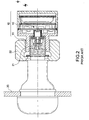
- a conventional tire pressure monitoring apparatus 10 includes an adapter 11 at the front end thereof that is screwed on an inflation valve 21 at the external side of the tire 20.
- a pressure-detecting element 12 is disposed within the tire pressure detector 10 for determining the tire pressure value of the tire 20. Meanwhile, a signal is transmitted to a receiving and displaying apparatus (not shown) within the vehicle.
- a lock nut 22 is installed for preventing the tire pressure detector 10 from unauthorized removal by the act of stealing.
- the above-mentioned tire pressure detector 10 has no problem in installing at a normal vehicle and applying thereto.
- some consumers have provided a few feedbacks.
- the heavy vehicles like trucks or tourist coaches have a left and a right tire 20 at the front while the left and right tires at the rear each has a combination of an internal and an external tire 20a, 20b both of which are mounted on a drive shaft 23. Accordingly, the installation of the front tire 20 and the external tire 20b has no problem.
- the internal tire 20a will be blocked by the external tire 20b. Passing through the hole 24 of the external wheel rim is therefore required for the inflation. In this way, the inflation of the internal tire 20a via the inflation valve (not shown) is possible.
- the tire pressure detector 10 As shown in FIG. 2 , is installed on the inflation valve at the internal side, the tire pressure detector 10 has to be removed first prior to the inflation. Nevertheless, the removal is much inconvenient since the tire pressure detector 10 is disposed next to the external tire 20b and therefore only little free room is available. In addition, it brings also difficulties to re-screw the tire pressure detector 10 in position when each inflation operation is completed. To carry out the above-mentioned operation within such a narrow space between the internal and external tires does consume much time and cost. This doesn't fulfill the requirement of the economic benefit.
- a connecting assembly for a wireless tire pressure monitoring apparatus that is formed in a branch joint with a first tube, a second tube, and a third tube.
- a connecting assembly for a wireless tire pressure monitoring apparatus in accordance with the invention includes:
- a connecting assembly 70 in accordance with the invention includes a main body 30, an adapter 50, and an air nozzle 60.
- the main body 30 is formed in a branch joint with a first tube 31, a second tube 32, and a third tube 33.
- the first tube 31 and the third tube 33 are communicated with each other in axial direction while the second tube 32 is perpendicular to the first tube 31 and the third tube 33, thereby creating a T-form.
- a penetration needle 40 with a first vent hole 41 is positioned within the first tube 31.
- the external wall of the second tube 32 is fitted with a first threaded section 321.
- a second threaded section 331 is formed on the internal wall of the third tube 33.
- the external wall of the third tube 33 is provided with a third threaded section 332 having the same diameter as an inflation valve 21.
- the adapter 50 is attached to an end port of the first tube 31 and mounted on the external wall of the penetration needle 40.
- the internal wall of the adapter 50 is provided with a fourth thread 51 screwed to the inflation valve 21.
- the adapter 50 enables the connection between the main body 30 and the inflation valve 21 for establishing an airway. Therefore, the main body 30 can be integrally formed (not shown). Alternatively, the adapter 50 can be individually formed and then attached to the main body 30. These are applicable embodiments, but should not restricted thereto. It is preferable that the adapter 50 is pivotally attached to the main body 30. In other words, the adapter 50 creates a detachable connection to the main body 30.
- the adapter 50 includes a sleeve portion 53 with a smaller diameter at a contact end to the first tube 31.
- the middle part of the penetration needle 40 is provided with a flange 42 corresponding to the sleeve portion 53.
- the flange 42 is used to position the sleeve portion 53 without clamping it.
- a part of the penetration needle 40 is fixed within the first tube 31 such that the sleeve portion 53 of the adapter 50 is mounted between the penetration needle 40 and the first tube 31.
- a smooth connection between the main body 30 of a T-shaped connecting assembly 80 and the inflation valve 21 is established only by turning the adapter 50 without turning the main body 30 when the adapter 50 connects the main body 30 to the inflation valve 21.
- the internal section of the adapter 50 is formed into a polygonal body such as into hexagonal body. Accordingly, the adapter 50 can be conveniently screwed with a screwing tool to the inflation valve 21.
- an air nozzle 60 having the same structure as the conventional inflation valve 21 is screwed into the third tube 33 such that the third tube 33 is normally maintained in a closed position.
- the air nozzle 60 includes a hollow sleeve portion 61 screwed into the third tube 33, thereby forming a second vent hole 62.
- An actuating pin 63 axially passing through the second vent hole 62 is mounted on the sleeve portion 61.
- a spring 64 is mounted on the sleeve portion 61.
- the tail of the sleeve portion 61 is formed into a tapering air inlet 65.
- the tail of the actuating pin 63 includes a compression cover 66 for opening and closing the air inlet 65. In this way, the actuating pin 63 is shifted outwards in the ordinary state by the tension of the spring 64 such that the air inlet 65 of the second vent hole 62 is closed by the compression cover 66. As a result, the escape of the air pressure of the tire from the third tube 33 can be avoided.
- a washer 44 is disposed on a contact surface between the penetration needle 40 and the first tube 31.
- a sealing ring 43 is disposed at an internal side of the flange 42 of the penetration needle 40.
- the penetration needle 40 creates a threaded connection to the first tube 313 and lies against the washer 44.
- the penetration needle 40 is forced to push against a valve stem 211 of the inflation valve 21 when the adapter 50 is screwed to the inflation valve 21.
- the air pressure within the tire 20 can flow through the first tube 31 into the main body 30.
- a tire pressure detector 10 mounted on the second tube 32 can perform the tire pressure detection operation.
- the connecting assembly 70 in accordance with the invention may ensure a reliable connection of the tire pressure detector 10 to the second tube 32, thereby creating a free air passage.
- the tire 20 can be directly inflated via the third tube 33 without pulling the tire pressure detector 10 out of the second tube 32.
- the third tube 33 has the same function as the inflation valve 21.
- the actuating pin 63 In fitting an inflating adapter (not shown) into the third tube 33, the actuating pin 63 is retracted inwards such that the compression cover 66 is removed from the air inlet 65 of the second vent hole 62 for a smooth entrance of the inflating air. Thereafter, the inflating air passes through the first vent hole 41 of the penetration needle 40 of the first tube 31 so that the inflation via the inflation valve 21 can be done. After the inflation is completed, the actuating pin 63 is returned by the tension of the spring 64 to the closed position (see FIG. 5 ) where the compression cover 66 lies against the air inlet 65 of the second vent hole 62.
- the invention employs the connecting assembly 70 so that it is not necessary to pull out the tire pressure detector 10 when the tire is inflated. It proves to be practical and convenient and effectively resolves the conventional problems.
- the tire pressure detector 10 is not the object of the invention so that its structure and principle are not detailed hereinafter.
- the tire pressure detector 10 in accordance with the invention relates to the patented product of U.S. Pat. No. 6,993,962 . Other tire pressure detectors 10 are also applicable.
Landscapes
- Engineering & Computer Science (AREA)
- Mechanical Engineering (AREA)
- Measuring Fluid Pressure (AREA)
Priority Applications (1)
| Application Number | Priority Date | Filing Date | Title |
|---|---|---|---|
| EP07000008A EP1942018A1 (fr) | 2007-01-02 | 2007-01-02 | Ensemble de connexion pour un appareil de surveillance de la pression des pneus sans fil |
Applications Claiming Priority (1)
| Application Number | Priority Date | Filing Date | Title |
|---|---|---|---|
| EP07000008A EP1942018A1 (fr) | 2007-01-02 | 2007-01-02 | Ensemble de connexion pour un appareil de surveillance de la pression des pneus sans fil |
Publications (1)
| Publication Number | Publication Date |
|---|---|
| EP1942018A1 true EP1942018A1 (fr) | 2008-07-09 |
Family
ID=37810327
Family Applications (1)
| Application Number | Title | Priority Date | Filing Date |
|---|---|---|---|
| EP07000008A Withdrawn EP1942018A1 (fr) | 2007-01-02 | 2007-01-02 | Ensemble de connexion pour un appareil de surveillance de la pression des pneus sans fil |
Country Status (1)
| Country | Link |
|---|---|
| EP (1) | EP1942018A1 (fr) |
Cited By (5)
| Publication number | Priority date | Publication date | Assignee | Title |
|---|---|---|---|---|
| EP2465712A1 (fr) * | 2010-12-17 | 2012-06-20 | Bridgestone Europe N.V. | Système de surveillance pneumatique de pneu |
| ITTO20110093A1 (it) * | 2011-02-04 | 2012-08-05 | Bridgestone Europ N V | Sistema di controllo della pressione di pneumatici |
| DE102014205923A1 (de) * | 2014-03-31 | 2015-10-01 | Aktiebolaget Skf | Modul zum Erfassen einer physikalischen Größe eines gasförmigen Mediums |
| WO2020165451A1 (fr) * | 2019-02-14 | 2020-08-20 | Meggitt Sa | Ensemble capteur permettant la détermination d'une propriété physique d'un véhicule |
| WO2023123831A1 (fr) * | 2021-12-30 | 2023-07-06 | 万通智控科技股份有限公司 | Structure de fixation filetée |
Citations (4)
| Publication number | Priority date | Publication date | Assignee | Title |
|---|---|---|---|---|
| US1181133A (en) * | 1910-04-29 | 1916-05-02 | Schraders Son Inc | Pressure-gage. |
| FR76178E (fr) * | 1958-08-16 | 1961-09-22 | Capuchon de valve exécuté sous forme de manomètre, pour pneumatiques de véhicules, notamment de véhicules automobiles | |
| AU1177776A (en) * | 1975-03-13 | 1977-09-15 | French E | Tyre failure alarm including radio transmitter |
| US6993962B1 (en) * | 2005-03-11 | 2006-02-07 | Yueh-Ying Ko | Electronic wireless tire pressure monitoring apparatus |
-
2007
- 2007-01-02 EP EP07000008A patent/EP1942018A1/fr not_active Withdrawn
Patent Citations (4)
| Publication number | Priority date | Publication date | Assignee | Title |
|---|---|---|---|---|
| US1181133A (en) * | 1910-04-29 | 1916-05-02 | Schraders Son Inc | Pressure-gage. |
| FR76178E (fr) * | 1958-08-16 | 1961-09-22 | Capuchon de valve exécuté sous forme de manomètre, pour pneumatiques de véhicules, notamment de véhicules automobiles | |
| AU1177776A (en) * | 1975-03-13 | 1977-09-15 | French E | Tyre failure alarm including radio transmitter |
| US6993962B1 (en) * | 2005-03-11 | 2006-02-07 | Yueh-Ying Ko | Electronic wireless tire pressure monitoring apparatus |
Cited By (9)
| Publication number | Priority date | Publication date | Assignee | Title |
|---|---|---|---|---|
| EP2465712A1 (fr) * | 2010-12-17 | 2012-06-20 | Bridgestone Europe N.V. | Système de surveillance pneumatique de pneu |
| ITTO20110093A1 (it) * | 2011-02-04 | 2012-08-05 | Bridgestone Europ N V | Sistema di controllo della pressione di pneumatici |
| DE102014205923A1 (de) * | 2014-03-31 | 2015-10-01 | Aktiebolaget Skf | Modul zum Erfassen einer physikalischen Größe eines gasförmigen Mediums |
| US9796221B2 (en) | 2014-03-31 | 2017-10-24 | Aktiebolaget Skf | Module for detecting a physical value of a gaseous medium |
| DE102014205923B4 (de) | 2014-03-31 | 2023-06-07 | Aktiebolaget Skf | Modul zum Erfassen einer physikalischen Größe eines gasförmigen Mediums |
| WO2020165451A1 (fr) * | 2019-02-14 | 2020-08-20 | Meggitt Sa | Ensemble capteur permettant la détermination d'une propriété physique d'un véhicule |
| CN113424035A (zh) * | 2019-02-14 | 2021-09-21 | 梅吉特股份有限公司 | 用于确定交通工具的物理特性的传感器组件 |
| US11913848B2 (en) | 2019-02-14 | 2024-02-27 | Meggitt Sa | Sensor assembly for determining a physical property of a vehicle including a locking arrangement and first and second controllable switches |
| WO2023123831A1 (fr) * | 2021-12-30 | 2023-07-06 | 万通智控科技股份有限公司 | Structure de fixation filetée |
Similar Documents
| Publication | Publication Date | Title |
|---|---|---|
| US20080149244A1 (en) | Connecting assembly for a wireless tire pressure monitoring apparatus | |
| EP1942018A1 (fr) | Ensemble de connexion pour un appareil de surveillance de la pression des pneus sans fil | |
| US8245747B2 (en) | Tire valve and process for removing it | |
| KR101137813B1 (ko) | 타이어 압력 모니터링 시스템 및 그의 타이어센서 | |
| US8146413B1 (en) | Two-port tire valve stem | |
| US7536904B1 (en) | Tire pressure detector and valve stem assembly | |
| US20160167463A1 (en) | Measurement module and assembly method for such a module on a wheel rim | |
| US11970029B2 (en) | Adapter, tyre parameter monitoring system and method for mounting a tyre parameter monitoring system onto a wheel rim | |
| US5746243A (en) | Valved inflation adapter | |
| WO2014019645A1 (fr) | Module de roue comportant une valve de gonflage elastiquement deformable pour un systeme de surveillance de la pression des pneus | |
| US20030217595A1 (en) | Remote tire pressure monitoring system with plastic thin-walled valve cap and method of installing the monitoring system | |
| US20130068318A1 (en) | Valve stem repair kit and method | |
| US9616719B1 (en) | Valve cap and core tool | |
| US5839180A (en) | Stud installer for wheel studs | |
| US20140109982A1 (en) | Valve stem repair kit and method | |
| TWI332559B (fr) | ||
| US4398574A (en) | Method for inflating dual pneumatic tires | |
| US4724880A (en) | Apparatus for maintaining a spare tire fully inflated | |
| EP2110268B1 (fr) | Procédé et dispositif pour verrouiller un pneu dans un jante | |
| AU2019100092A4 (en) | Spare Tyre Valve Extension | |
| US20120097309A1 (en) | Method and device for locking tyres | |
| JP3130507U (ja) | タイヤ空気圧警報装置用の組込みモジュール | |
| US11766768B2 (en) | Spare tire tool kit | |
| US1177063A (en) | Valve for pneumatic tires. | |
| WO2022001081A1 (fr) | Manomètre pour pneu externe |
Legal Events
| Date | Code | Title | Description |
|---|---|---|---|
| PUAI | Public reference made under article 153(3) epc to a published international application that has entered the european phase |
Free format text: ORIGINAL CODE: 0009012 |
|
| AK | Designated contracting states |
Kind code of ref document: A1 Designated state(s): AT BE BG CH CY CZ DE DK EE ES FI FR GB GR HU IE IS IT LI LT LU LV MC NL PL PT RO SE SI SK TR |
|
| AX | Request for extension of the european patent |
Extension state: AL BA HR MK RS |
|
| AKX | Designation fees paid | ||
| STAA | Information on the status of an ep patent application or granted ep patent |
Free format text: STATUS: THE APPLICATION IS DEEMED TO BE WITHDRAWN |
|
| 18D | Application deemed to be withdrawn |
Effective date: 20090110 |
|
| REG | Reference to a national code |
Ref country code: DE Ref legal event code: 8566 |