JP2012144232A - Support structure of support - Google Patents
Support structure of support Download PDFInfo
- Publication number
- JP2012144232A JP2012144232A JP2011006378A JP2011006378A JP2012144232A JP 2012144232 A JP2012144232 A JP 2012144232A JP 2011006378 A JP2011006378 A JP 2011006378A JP 2011006378 A JP2011006378 A JP 2011006378A JP 2012144232 A JP2012144232 A JP 2012144232A
- Authority
- JP
- Japan
- Prior art keywords
- support
- bracket
- spring
- support structure
- base body
- Prior art date
- Legal status (The legal status is an assumption and is not a legal conclusion. Google has not performed a legal analysis and makes no representation as to the accuracy of the status listed.)
- Granted
Links
- 238000012545 processing Methods 0.000 claims description 4
- 230000010485 coping Effects 0.000 abstract 3
- 230000008961 swelling Effects 0.000 abstract 1
- 230000000694 effects Effects 0.000 description 17
- 238000010586 diagram Methods 0.000 description 9
- 238000003780 insertion Methods 0.000 description 9
- 230000037431 insertion Effects 0.000 description 9
- 238000004519 manufacturing process Methods 0.000 description 5
- 238000000034 method Methods 0.000 description 5
- 230000002265 prevention Effects 0.000 description 5
- 230000003139 buffering effect Effects 0.000 description 4
- 239000002184 metal Substances 0.000 description 4
- 238000005452 bending Methods 0.000 description 3
- 230000000116 mitigating effect Effects 0.000 description 3
- 230000002093 peripheral effect Effects 0.000 description 3
- 238000003825 pressing Methods 0.000 description 3
- 230000035807 sensation Effects 0.000 description 3
- 208000027418 Wounds and injury Diseases 0.000 description 2
- 230000006378 damage Effects 0.000 description 2
- 230000006870 function Effects 0.000 description 2
- 208000014674 injury Diseases 0.000 description 2
- 239000000463 material Substances 0.000 description 2
- 238000003466 welding Methods 0.000 description 2
- 238000010521 absorption reaction Methods 0.000 description 1
- 230000003466 anti-cipated effect Effects 0.000 description 1
- 238000006243 chemical reaction Methods 0.000 description 1
- 230000000994 depressogenic effect Effects 0.000 description 1
- 238000009434 installation Methods 0.000 description 1
- 238000011835 investigation Methods 0.000 description 1
- 238000012423 maintenance Methods 0.000 description 1
- 239000011347 resin Substances 0.000 description 1
- 229920005989 resin Polymers 0.000 description 1
- 230000035939 shock Effects 0.000 description 1
Images


Landscapes
- Seats For Vehicles (AREA)
- Chair Legs, Seat Parts, And Backrests (AREA)
Abstract
Description
本発明は、ヘッドレストサポート(サポート)と、このサポートを支持し、シートのフレームに取付けられる角柱形状のブラケットとで構成したサポートの支持構造に関する。 The present invention relates to a support support structure including a headrest support (support) and a prismatic bracket that supports the support and is attached to a frame of a seat.
車輌の如く、走行状態の良否、で、かつ体感的な感覚とか、道路状況、走行態様、又は気候等のあらゆる条件下に対応可能なサポートとブラケットにおいて、その走行中、又はアイドリンク中等に発生するガタ防止(騒音防止)を図る構造として、本発明者は、既に、提案している。その一例を説明すると、特開2002−79333の「金属製筒体および金属製ブラケット」(文献1とする)の[0024]において、車両前後方向へ配向されるサポートの外周壁面に、切り欠き溝を設けて樹脂バネでなる可撓片を対で形成し、この可撓片を押圧するようにして、金属製ブラケットに挿入し、可撓片が、金属製ブラケットの内辺側により押圧されて内方に撓む構造であり、この撓みを利用して、サポートの車両前後方向へのガタつきを防止することを意図する。この構造で、現状では、十分と考えられる。しかし、車内(室内)の静寂と、EV自動車の普及に伴って、更なるガタ防止が要望される状況となった。 It occurs during driving or eye-drink in the support and bracket that can handle all conditions such as road condition, driving mode, climate etc. The present inventor has already proposed a structure for preventing backlash (noise prevention). As an example, in [0024] of “Metal Cylinder and Metal Bracket” (referred to as Document 1) of JP-A-2002-79333, a notch groove is formed on the outer peripheral wall surface of the support oriented in the vehicle front-rear direction. A flexible piece made of a resin spring is formed in pairs, and the flexible piece is inserted into a metal bracket so as to be pressed, and the flexible piece is pressed by the inner side of the metal bracket. It is a structure that bends inward and is intended to prevent rattling of the support in the longitudinal direction of the vehicle using this bend. This structure is considered sufficient at present. However, with the quietness of the interior (indoors) and the spread of EV cars, further backlash prevention has been demanded.
このような見地から、先行文献で、調査した結果を、以下に概述する。 From this point of view, the results of investigations in prior literature are outlined below.
実開平3−13858号の「ヘッドレストステーの支持装置」(文献2とする)には、ブラケットに長孔を形成し、この長孔には、ブラケットの上部より嵌着したステー貫通孔を備えたスプリング板(板ばね)の弾性部を嵌挿し、この嵌挿した弾性部で、ステーの脚部を弾圧する構造として、ガタ防止を図る構造である。しかし、この考案は、弾性部がブラケットの横断方向に対応した、横方向の線接触の弾性であり、弾性不足の問題と、ステーのスリップ防止に配慮がなされていないこと、等の問題がある。また、異分野で、実開昭61−118781号の「筆記具のキャップ」(文献3とする)には、キャップの内部に、帯状の板バネ部を膨出形成したバネ体を挿入し、この板バネ部で、万年筆の本体を嵌着する構造である。しかし、この考案は、単にバネ体を嵌着する構造であり、車輌の如く、走行、又は移動とか、振動する物には、不向きである。さらに、異分野で、特開2004−238058の「容器」(文献4とする)には、把手部材を備えたリング部材の内面に、対で板バネ部材を設け、このリング部材を容器本体に嵌入し、このリング部材に設けた板バネ部材で、リング部材と容器本体を一体化するとともに、容器本体を廃棄する際に、リング部材を取外し可能とする構造であり、この把手部材とリング部材の再利用を図ることにある。しかし、この考案も、文献3と同じ問題がある。
Japanese Utility Model Laid-Open No. 3-13858 “Headrest Stay Support Device” (referred to as Document 2) has a long hole in the bracket, and this long hole has a stay through hole fitted from the upper part of the bracket. A structure for preventing backlash is a structure in which an elastic portion of a spring plate (plate spring) is inserted and the elastic portion thus inserted presses the leg portion of the stay. However, this device has problems such as the elasticity of the line contact in the horizontal direction corresponding to the transverse direction of the bracket, the problem of insufficient elasticity, and the consideration of preventing slipping of the stay. . Also, in a different field, a spring body in which a strip-shaped leaf spring portion is bulged is inserted into the “writing instrument cap” (referred to as reference 3) of Japanese Utility Model Publication No. 61-118781. It is a structure in which the body of the fountain pen is fitted with a leaf spring. However, this device has a structure in which a spring body is simply fitted, and is not suitable for an object that travels or moves or vibrates like a vehicle. Further, in another field, the “container” (referred to as reference 4) of Japanese Patent Application Laid-Open No. 2004-238058 is provided with a pair of leaf spring members on the inner surface of a ring member provided with a handle member, and this ring member is attached to the container body. The ring member is inserted into the ring member, and the ring member and the container main body are integrated, and the ring member can be removed when the container main body is discarded. Is to recycle. However, this device also has the same problem as
以上で概述した文献1〜文献4と、従来の構造では、この種の車輌の如く、走行状態の良否、又は体感的な感覚とか、道路状況、走行態様、又は気候等のあらゆる条件下に対応可能なサポートとブラケットとのガタ発生をなく得るには、まだ改良の余地がある。殊に、室内の静寂の確保と、EV自動車の静寂性に対応可能とすること、又は安全運転と、集中した運転状態を確保可能とするには、十分でないのが現況である。
In the above-described
上記に鑑み、本発明は、以下の目的を達成することを意図する。
「イ」 ブラケットにスプリングを配備することで、例えば、車輌の如く、走行状態の良否、又は体感的な感覚とか、道路状況、走行態様、又は気候等のあらゆる条件下に対応可能なサポートとブラケットとのガタ発生をなくし、室内の静寂の確保と、EV自動車の静寂性に対応可能とすること、又は安全運転と、集中した運転状態を確保可能とする。
「イ‘」 サポートにスプリングを配備することで、例えば、車輌の如く、走行状態の良否、又は体感的な感覚とか、道路状況、走行態様、又は気候等のあらゆる条件下に対応可能なサポートとブラケットとのガタ発生をなくし、室内の静寂の確保と、EV自動車の静寂性に対応可能とすること、又は安全運転と、集中した運転状態を確保可能とする。
「ロ」 ガソリン車で発生するエンジン音で打消されて、従来は問題とならなかった、この種のガタの発生を、無くすることにある。
「ハ」 サポートのガタ防止を図ることで、ヘッドレストのブレ防止と、頭部への振動防止を図り、快適な乗車を確保する。
「ニ」 ブラケットの上側端部、及び/又は、下側端部にスプリングを配備することで、どのような構造のブラケットでも取付け可能とする。
「ニ‘」 サポートの上側端部、及び/又は、下側端部にスプリングを配備することで、どのような構造のサポートでも取付け可能とする。
「ホ」 ブラケットの上側端部、及び/又は、下側端部にスプリングを配備することで、簡易にガタ防止を図りつつ、その効果を確保することにある。
「ホ‘」 サポートの上側端部、及び/又は、下側端部にスプリングを配備することで、簡易にガタ防止を図りつつ、その効果を確保することにある。
「へ」 ブラケットとスプリングとの組合せ構造であり、構造の簡素化と、低コスト化、又は製造の効率化等を図る。
「へ‘」 サポートとスプリングとの組合せ構造であり、構造の簡素化と、低コスト化、又は製造の効率化等を図る。
「ト」 サポートの挿入の容易化と、ガタ防止を有効に達成するために、スプリングを板材とし、かつブラケットの長手方向に配備する。
「ト‘」 サポートの挿入の容易化と、ガタ防止を有効に達成するために、スプリングに凸部を設けるとともに、サポートに対応する凹部を設ける。
「チ」 前記板状のスプリングを、確実な、かつワンタッチで配備するために、ブラケットの壁体の上側端部、及び/又は、下側端部にスプリングを配備する。
「チ‘」 コ字形状のスプリングを、確実な、かつワンタッチで配備するために、スプリングの下端に誘導片を設ける。
In view of the above, the present invention intends to achieve the following objects.
“I” By providing a spring on the bracket, for example, like a vehicle, the support and bracket can be used in all conditions such as good or bad running condition or sense of sensation, road conditions, driving mode, or climate. The generation of noise is eliminated, and it is possible to ensure the quietness of the room and the quietness of the EV car, or to ensure the safe driving and the concentrated driving state.
“I '” By providing a spring for the support, for example, like a vehicle, it can be used for all conditions such as road condition, driving mode, climate, etc. Occurrence of rattling with the bracket is eliminated, and it is possible to ensure the quietness of the room and the quietness of the EV car, or to ensure safe driving and a concentrated driving state.
“B” This is to eliminate the occurrence of this kind of backlash, which was not a problem in the past because it was canceled by the engine sound generated in gasoline cars.
"C" By preventing backlash of the support, the headrest is prevented from shaking and the head is prevented from vibrating, ensuring a comfortable ride.
“D” By installing a spring at the upper end and / or the lower end of the bracket, it is possible to mount a bracket of any structure.
"D '" Supports of any structure can be mounted by providing a spring at the upper end and / or lower end of the support.
“E” By providing a spring at the upper end and / or lower end of the bracket, it is possible to easily prevent backlash and to secure its effect.
“Eh ′” By providing a spring at the upper end and / or lower end of the support, it is possible to easily prevent backlash and to secure its effect.
“He” It is a combination structure of a bracket and a spring. The structure is simplified, the cost is reduced, or the manufacturing efficiency is improved.
“He '” It is a combination structure of support and spring, and simplifies the structure, lowers the cost, or improves the production efficiency.
In order to facilitate the insertion of the “G” support and to prevent backlash effectively, the spring is used as a plate and is provided in the longitudinal direction of the bracket.
In order to facilitate the insertion of the support and to prevent backlash effectively, the spring is provided with a convex portion and a concave portion corresponding to the support.
“H” In order to deploy the plate-like spring in a reliable and one-touch manner, a spring is deployed at the upper end and / or the lower end of the wall of the bracket.
In order to deploy a U-shaped spring in a reliable and one-touch manner, a guide piece is provided at the lower end of the spring.
請求項1の発明は、前記「イ」〜「ニ」を達成することを意図する。
The invention of
請求項1は、サポートと、このサポートを支持し、シートのフレームに取付けられる角柱形状のブラケットとで構成したサポートの支持構造であって、
このブラケットの対峙方向に、スプリングを配設し、このスプリングに設けた弾性膨出部が、このブラケットの内辺側と、同一か、又は内方に位置する構成としたサポートの支持構造である。
This is a support support structure in which a spring is disposed in the opposite direction of the bracket, and an elastic bulge provided on the spring is located on the same side as or on the inner side of the bracket. .
請求項2〜4の発明は、前記「イ」〜「ニ」と、「ホ」を達成することを意図する。
The inventions of
請求項2は、請求項1に記載のサポートの支持構造であって、
前記ブラケットの対峙方向は、このブラケットの取付け側と前面側、又は左右側とする構成としたサポートの支持構造である。
The opposite direction of the bracket is a support support structure configured such that the bracket is mounted on the front side and the front side or the left and right sides.
請求項3は、請求項1に記載のサポートの支持構造であって、
前記ブラケットの上側端部か、下側端部、又は上下端部の一部を、拡径して拡径部を形成し、この拡径部に、前記スプリングを配設する構成としたサポートの支持構造である。
The support has a configuration in which the upper end portion, the lower end portion, or a part of the upper and lower end portions of the bracket is enlarged to form an enlarged diameter portion, and the spring is disposed in the enlarged diameter portion. Support structure.
請求項4は、請求項1に記載のサポートの支持構造であって、
前記スプリングは、ブラケットに固定されるベース体の縦方向の一面側に立設する構造であり、このベース体の係止凸部を、前記ブラケットの拡径部の外側に設けた係止凹部に係止するとともに、このベース体を、前記ブラケットの内側に至らしめ、かつこの内側に前記スプリングを配設する構成としたサポートの支持構造である。
The spring is configured to stand on one side in the vertical direction of the base body fixed to the bracket, and the locking projection of the base body is formed into a locking recess provided outside the enlarged diameter portion of the bracket. This is a support support structure in which the base body is brought to the inside of the bracket and the spring is disposed inside the bracket while being locked.
請求項5〜9の発明は、前記「イ」〜「ニ」と、「へ」を達成することを意図する。
The inventions of
請求項5は、請求項1に記載のサポートの支持構造であって、
前記ブラケットのフレームの取付け側には、クリンチ加工による凹凸の嵌合片を形成する構成としたサポートの支持構造である。
The support structure of the support is configured such that an uneven fitting piece is formed by clinching on the attachment side of the frame of the bracket.
請求項6は、請求項1に記載のサポートの支持構造であって、
前記ブラケットのフレームの取付け側には、繋ぎ加工による線状の繋ぎ部を形成する構成としたサポートの支持構造である。
The support structure of the support is configured such that a linear connecting portion is formed by connecting processing on the mounting side of the bracket frame.
請求項7は、請求項5に記載のサポートの支持構造であって、
前記ブラケットに、前記ベース体を配備した構造において、このベース体とスプリングを配備しない箇所に、前記クリンチ加工による凹凸の嵌合片を形成する構成としたサポートの支持構造である。
In the structure in which the base body is provided on the bracket, a support support structure in which the uneven fitting piece by the clinching process is formed in a place where the base body and the spring are not provided.
請求項8は、請求項4に記載のサポートの支持構造であって、
前記ベース体に、横向き、又は縦向きによる係止凸部を形成する構成としたサポートの支持構造である。
This is a support support structure in which a locking projection is formed on the base body in a horizontal direction or a vertical direction.
請求項9は、請求項1に記載のサポートの支持構造であって、
前記スプリングは、半円弧状か、弓型形状、擬似弓型形状か、又は波々形状とする構成としたサポートの支持構造である。
The spring is a support support structure configured to have a semicircular arc shape, an arc shape, a pseudo arc shape, or a wave shape.
請求項10の発明は、前記「イ」〜「へ」と、「ト」、「チ」を達成することを意図する。
The invention of
請求項10は、請求項1に記載のサポートの支持構造であって、
前記スプリングは、正面視して、細幅板状とする構成としたサポートの支持構造である。
The spring is a support support structure having a narrow plate shape when viewed from the front.
請求項11の発明は、前記「イ」〜「ハ」を達成することを意図する。
The invention of
請求項11は、請求項1に記載のサポートの支持構造であって、
前記ブラケットの取付け側、左右側、又は前面側の全側に、前記スプリングを配設する構成としたサポートの支持構造である。
It is a support support structure in which the spring is arranged on all sides of the bracket mounting side, left and right side, or front side.
請求項12、13の発明は、前記「イ」〜「へ」と、「ト」、「チ」を達成することを意図する。 The inventions of claims 12 and 13 are intended to achieve the “a” to “he”, “g” and “h”.
請求項12は、請求項4に記載のサポートの支持構造であって、
前記ブラケットの取付け側と前面側、又は左右側の何れかの側に係止凹部を形成し、この係止凹部に、前記ベース体に設けた係止凸部を係止し、また、このベース体の連結側を、前記ブラケットの端側を迂回し、このベース体の内側にスプリングが設けられる構成としたサポートの支持構造である。
Claim 12 is a support structure of the support according to
A locking recess is formed on either the mounting side and the front surface side or the left and right sides of the bracket, and a locking projection provided on the base body is locked in the locking recess. This is a support support structure in which the connecting side of the body bypasses the end side of the bracket and a spring is provided inside the base body.
請求項13は、請求項11に記載のサポートの支持構造であって、
前記ブラケットの取付け側、左右側、又は前面側の全側に係止凹部を形成し、この係止凹部に、前記ベース体に設けた係止凸部を係止し、また、このベース体の連結側を、前記ブラケットの端側を迂回し、このベース体の内側にスプリングが設けられる構成としたサポートの支持構造である。
Claim 13 is a support support structure according to
A locking recess is formed on the mounting side, the left and right sides or the front side of the bracket, and a locking protrusion provided on the base body is locked in the locking recess. This is a support support structure in which the connection side is configured to bypass the end side of the bracket and to have a spring provided inside the base body.
請求項14の発明は、前記「イ」〜「ハ」を達成することを意図する。
The invention of
請求項14は、請求項11に記載のサポートの支持構造であって、
前記ベース体は、その外側が細幅の平板状で、その内側が細幅の前記スプリングである構成としたサポートの支持構造である。
The base body is a support support structure in which the outside is a narrow flat plate shape and the inside is the narrow spring.
請求項15の発明は、前記「イ‘」と、「ロ」、「ハ」と、「ニ‘」、「ホ‘」と、「へ‘」を達成することを意図する。 The fifteenth aspect of the invention is intended to achieve the above-mentioned “I”, “B”, “C”, “D”, “H” and “H”.
請求項15は、サポートと、このサポートを支持し、シートのフレームに取付けられる角柱形状のブラケットとで構成したサポートの支持構造であって、
このサポートにスプリングを捲装し、このスプリングを圧着して前記ブラケットに挿入し、このスプリングで、前記ブラケットに前記サポートを弾着可能とする構成としたサポートの支持構造である。
Claim 15 is a support support structure composed of a support and a prism-shaped bracket that supports the support and is attached to a frame of a seat,
The support is a support structure in which a spring is mounted on the support, the spring is crimped and inserted into the bracket, and the support can be elastically attached to the bracket with the spring.
請求項16の発明は、前記「イ‘」と、「ロ」、「ハ」と、「ニ‘」、「ホ‘」と、「へ‘」と、「ト‘」を達成することを意図する。 The invention of claim 16 is intended to achieve the above-mentioned “I '”, “B”, “C”, “D”, “H”, “He”, and “G”. To do.
請求項16は、請求項15に記載のサポートの支持構造であって、
前記スプリングは、前記サポートの長手方向を横断するように捲装するとともに、このスプリングの長手方向の下側に誘導片を設け、この誘導片の先端部が、前記スプリングの外側より内方に位置する構成としたサポートの支持構造である。
Claim 16 is a support structure of the support according to claim 15,
The spring is equipped so as to cross the longitudinal direction of the support, and a guide piece is provided on the lower side of the spring in the longitudinal direction, and the leading end of the guide piece is positioned inward from the outside of the spring. It is the support structure of the support made into the structure to do.
請求項17の発明は、前記「イ‘」と、「ロ」、「ハ」と、「ニ‘」、「ホ‘」と、「へ‘」と、「チ‘」を達成することを意図する。 The invention of claim 17 is intended to achieve the above-mentioned “I”, “B”, “C”, “D”, “H”, “H”, and “C”. To do.
請求項17は、請求項15に記載のサポートの支持構造であって、
このスプリングには、内方に向かって陥没した凸部を一個、又は複数個設ける構成とし、この一個、又は複数個の凸部に対応する凹部を、前記サポートの外側に、一個、又は複数個設ける構成としたサポートの支持構造である。
Claim 17 is a support structure of the support according to claim 15,
The spring has a configuration in which one or a plurality of convex portions recessed inward are provided, and one or a plurality of concave portions corresponding to the one or the plurality of convex portions are provided on the outside of the support. It is the support structure of the support set as the structure to provide.
請求項18・19の発明は、前記「イ‘」と、「ロ」、「ハ」と、「ニ‘」、「ホ‘」と、「へ‘」を達成することを意図する。 The inventions of claims 18 and 19 are intended to achieve the “i”, “b”, “ha”, “d”, “ho”, and “he”.
請求項18は、サポートと、このサポートを支持し、シートのフレームに取付けられる角柱形状のブラケットとで構成したサポートの支持構造であって、
このサポートの横断方向に開設した空間にスプリングを挿設し、このスプリングで、このサポートの鰭片を放射方向に膨出するとともに、この鰭片の膨出を、前記ブラケットに圧着して挿入し、この鰭片とスプリングで、前記ブラケットに前記サポートを弾着可能とする構成としたサポートの支持構造である。
Claim 18 is a support support structure composed of a support and a prism-shaped bracket that supports the support and is attached to a frame of a seat,
A spring is inserted into the space opened in the transverse direction of the support, and the flange of the support is swelled in the radial direction with this spring, and the bulge of the flange is inserted into the bracket by being crimped. The support structure of the support is configured such that the support can be elastically attached to the bracket by the flange piece and the spring.
請求項19は、請求項18に記載のサポートの支持構造であって、
前記スプリングは、横断方向において、コ字形状であって、その一方対峙側の自由端部を、放射方向に膨出することで第一弾性部とするとともに、その他方対峙側の基端部を、放射方向に膨出することで第二弾性部とし、この第一・第二弾性部を、前記ブラケットに圧着して挿入し、この鰭片とスプリングで、前記ブラケットに前記サポートを弾着可能とする構成としたサポートの支持構造である。
Claim 19 is the support structure of the support according to claim 18,
The spring is U-shaped in the transverse direction, and the free end portion on one side of the spring is swelled in the radial direction to form a first elastic portion, and the base end portion on the other side is on the other side. By bulging in the radial direction, it becomes a second elastic part, and the first and second elastic parts can be crimped and inserted into the bracket, and the support can be elastically attached to the bracket with this flange and spring. This is a support support structure having the structure as follows.
請求項20の発明は、前記「イ‘」と、「ロ」、「ハ」と、「ニ‘」、「ホ‘」と、「へ‘」と、「ト‘」を達成することを意図する。
The invention of
請求項20は、請求項15に記載のサポートの支持構造であって、
前記コ字形状のスプリングは、前記一方・他方対峙側と、この一方・他方対峙側を連結する連結側とで構成し、かつこの一方・他方対峙側と、この連結側の何れか一箇所か、又は複数箇所に、下向きの一片、又は複数片の誘導片を設ける構成としたサポートの支持構造である。
The U-shaped spring is composed of the one / other opposing side and a connecting side that connects the one / other opposing side, and the one / other opposing side is either one of the connecting sides. Or a support support structure in which a downwardly directed piece or a plurality of guide pieces are provided at a plurality of locations.
請求項21の発明は、前記「イ‘」と、「ロ」、「ハ」と、「ニ‘」、「ホ‘」と、「へ‘」と、「チ‘」を達成することを意図する。 The invention of claim 21 is intended to achieve the above-mentioned “I”, “B”, “C”, “D”, “H”, “He” and “Chi”. To do.
請求項21は、請求項18に記載のサポートの支持構造であって、
前記一方対峙側に設けた第一弾性部は、内側に凹設する中間部を経由し、前記コ字形状の連結側に至る基端部を有する構造とするとともに、前記他方対峙側に設けられた第二弾性部は、前記コ字形状の連結側を基端として設け、かつその一端には、内側に凹設する中間部を経由して延設した自由端部を備える構成としたサポートの支持構造である。
Claim 21 is a support support structure according to claim 18,
The first elastic portion provided on the one opposite side has a structure having a base end portion reaching the U-shaped connecting side via an intermediate portion recessed inward and provided on the other opposite side. The second elastic portion is provided with the U-shaped connecting side as a base end, and at one end of the support, a free end portion extending through an intermediate portion recessed inward is provided. Support structure.
請求項1の発明は、サポートと、サポートを支持し、シートのフレームに取付けられる角柱形状のブラケットとで構成したサポートの支持構造であって、
ブラケットの対峙方向に、スプリングを配設し、スプリングに設けた弾性膨出部が、ブラケットの内辺側と、同一か、又は内方に位置する構成としたサポートの支持構造である。
The invention of
This is a support support structure in which a spring is disposed in the opposite direction of the bracket, and an elastic bulge provided on the spring is located on the same side as or on the inner side of the bracket.
請求項1の発明は、効果「イ」〜「ニ」を達成することを意図する。
「イ」 ブラケットにスプリングを配備することで、車輌の如く、走行状態の良否、又は体感的な感覚とか、道路状況、走行態様、又は気候等のあらゆる条件下に対応可能なサポートとブラケットとのガタ発生をなくし、室内の静寂の確保と、EV自動車の静寂性に対応可能となること、又は安全運転と、集中した運転状態を確保可能となる。そして、また、従来のサポートの弾性手段を併用することで、このガタ防止の効果は、一層拡充できる。
「ロ」 ガソリン車で発生するエンジン音で打消されて、従来は問題とならなかった、この種のガタの発生を、無くし得る。
「ハ」 サポートのガタ防止を図ることで、ヘッドレストのブレ防止と、頭部への振動防止が図れ、また快適な乗車が確保できる。
「ニ」 ブラケットの上側端部、及び/又は、下側端部にスプリングを配備することで、どのような構造のブラケットでも取付け可能とする。
The invention of
“I” By providing a spring on the bracket, the support and bracket can be used under all conditions, such as a vehicle, whether it is in good driving condition or a sense of sensation, road conditions, driving conditions, or climate. Occurrence of rattling can be eliminated, and it is possible to ensure the quietness of the room and the quietness of the EV car, or to ensure safe driving and a concentrated driving state. And the effect of this play prevention can be further expanded by using together the elastic means of the conventional support.
“B” This type of backlash, which has not been a problem in the past, can be eliminated by being canceled by the engine sound generated in gasoline cars.
“C” By preventing backlash of the support, the headrest can be prevented from shaking and the head can be prevented from vibrating, and a comfortable ride can be secured.
“D” By installing a spring at the upper end and / or the lower end of the bracket, it is possible to mount a bracket of any structure.
請求項2の発明は、請求項1に記載のサポートの支持構造であって、
ブラケットの対峙方向は、ブラケットの取付け側と前面側、又は左右側とする構成としたサポートの支持構造である。
The invention of
The opposite direction of the bracket is a support support structure in which the bracket is mounted on the front side and the front side or the left and right sides.
請求項3は、請求項1に記載のサポートの支持構造であって、
前記ブラケットの上側端部か、下側端部、又は上下端部の一部を、拡径して拡径部を形成し、この拡径部に、前記スプリングを配設する構成としたサポートの支持構造である。
The support has a configuration in which the upper end portion, the lower end portion, or a part of the upper and lower end portions of the bracket is enlarged to form an enlarged diameter portion, and the spring is disposed in the enlarged diameter portion. Support structure.
請求項4は、請求項1に記載のサポートの支持構造であって、
前記スプリングは、ブラケットに固定されるベース体の縦方向の一面側に立設する構造であり、このベース体の係止凸部を、前記ブラケットの拡径部の外側に設けた係止凹部に係止するとともに、このベース体を、前記ブラケットの内側に至らしめ、かつこの内側に前記スプリングを配設する構成としたサポートの支持構造である。
The spring is configured to stand on one side in the vertical direction of the base body fixed to the bracket, and the locking projection of the base body is formed into a locking recess provided outside the enlarged diameter portion of the bracket. This is a support support structure in which the base body is brought to the inside of the bracket and the spring is disposed inside the bracket while being locked.
従って、請求項2〜4は、効果「イ」〜「ニ」の他に、「ホ」を達成できる特徴がある。
「ホ」 ブラケットの上側端部、及び/又は、下側端部にスプリングを配備することで、簡易にガタ防止が図れることと、その効果を確保できる。
Therefore, claims 2 to 4 have a feature that “e” can be achieved in addition to the effects “a” to “d”.
"E" By providing a spring at the upper end and / or lower end of the bracket, it is possible to easily prevent backlash and to secure the effect.
請求項5の発明は、請求項1に記載のサポートの支持構造であって、
ブラケットのフレームの取付け側には、クリンチ加工による凹凸の嵌合片を形成する構成としたサポートの支持構造である。
The invention according to
The support structure of the support is configured such that an uneven fitting piece is formed by clinching on the frame mounting side of the bracket.
請求項6の発明は、請求項1に記載のサポートの支持構造であって、
ブラケットのフレームの取付け側には、繋ぎ加工による線状の繋ぎ部を形成する構成としたサポートの支持構造である。
The invention of
The support structure of the support is configured such that a linear connecting portion is formed on the mounting side of the bracket frame.
請求項7の発明は、請求項4に記載のサポートの支持構造であって、
ブラケットに、ベース体を配備した構造において、ベース体とスプリングを配備しない箇所に、クリンチ加工による凹凸の嵌合片を形成する構成としたサポートの支持構造である。
The invention according to
In the structure in which the base body is provided on the bracket, the support support structure is configured such that a concave and convex fitting piece is formed by clinching at a location where the base body and the spring are not provided.
請求項8の発明は、請求項4に記載のサポートの支持構造であって、
ベース体に、横向き、又は縦向きによる係止凸部を形成する構成としたサポートの支持構造である。
The invention of
This is a support support structure in which a locking protrusion is formed in the base body in the horizontal direction or the vertical direction.
請求項9の発明は、請求項1に記載のサポートの支持構造であって、
スプリングは、半円弧状か、弓型形状、擬似弓型形状か、又は波々形状とする構成としたサポートの支持構造である。
The invention of
The spring is a support support structure configured to be semicircular, bow-shaped, pseudo-bow-shaped, or wave-shaped.
従って、請求項5〜9の発明は、効果「イ」〜「ニ」の他に、「へ」を達成できる特徴がある。
「へ」 ブラケットとスプリングとの組合せ構造であり、構造の簡素化と、低コスト化、又は製造の効率化等が図れる。
Therefore, the inventions of
“He” It is a combination structure of a bracket and a spring, and simplification of the structure, cost reduction, production efficiency, etc. can be achieved.
請求項10の発明は、請求項1に記載のサポートの支持構造であって、
前記スプリングは、正面視して、細幅板状とする構成としたサポートの支持構造である。
The invention of
The spring is a support support structure having a narrow plate shape when viewed from the front.
従って、請求項10は、効果「イ」〜「へ」の他に「ト」、「チ」を達成することを意図する。
「ト」 サポートの挿入の容易化と、ガタ防止を有効に達成するために、スプリングを板材とし、かつブラケットの長手方向に配備できる。
「チ」 前記板状のスプリングを、確実な、かつワンタッチで配備するために、ブラケットの壁体の上側端部、及び/又は、下側端部にスプリングを配備できる。
Therefore, claim 10 intends to achieve “G” and “H” in addition to the effects “A” to “F”.
In order to facilitate the insertion of the “G” support and to prevent backlash effectively, the spring can be a plate and can be arranged in the longitudinal direction of the bracket.
“H” In order to deploy the plate-like spring with certainty and one touch, a spring can be deployed at the upper end and / or the lower end of the wall of the bracket.
請求項11は、請求項1に記載のサポートの支持構造であって、
前記ブラケットの取付け側、左右側、又は前面側の全側に、前記スプリングを配設する構成としたサポートの支持構造である。
It is a support support structure in which the spring is arranged on all sides of the bracket mounting side, left and right side, or front side.
従って、請求項11は、効果「イ」〜「ハ」を達成できる特徴がある。 Therefore, claim 11 is characterized in that the effects “i” to “c” can be achieved.
請求項12は、請求項4に記載のサポートの支持構造であって、
ブラケットの取付け側と前面側、又は左右側の何れかの側に係止凹部を形成し、係止凹部に、ベース体に設けた係止凸部を係止し、また、ベース体の連結側を、ブラケットの端側を迂回し、ベース体の内側にスプリングが設けられる構成としたサポートの支持構造である。
Claim 12 is a support structure of the support according to
A locking recess is formed on either the mounting side and front side of the bracket, or on the left or right side, and a locking protrusion provided on the base body is locked in the locking recess. Is a support support structure in which the end side of the bracket is bypassed and a spring is provided inside the base body.
請求項13は、請求項11に記載のサポートの支持構造であって、
ブラケットの取付け側、左右側、又は前面側の全側に係止凹部を形成し、係止凹部に、前記ベース体に設けた係止凸部を係止し、また、ベース体の連結側を、ブラケットの端側を迂回し、ベース体の内側にスプリングが設けられる構成としたサポートの支持構造である。
Claim 13 is a support support structure according to
Locking recesses are formed on all sides of the bracket mounting side, left and right sides, or front side, and locking protrusions provided on the base body are locked in the locking recesses, and the connecting side of the base body is The support support structure is configured such that the end of the bracket is bypassed and a spring is provided inside the base body.
従って、請求項12、13の発明は、効果「イ」〜「へ」の他に、「ト」、「チ」を達成できる特徴がある。 Therefore, the inventions of claims 12 and 13 are characterized in that “G” and “H” can be achieved in addition to the effects “A” to “F”.
請求項14の発明は、請求項11に記載のサポートの支持構造であって、
ベース体は、その外側が細幅の平板状で、その内側が細幅の前記スプリングである構成としたサポートの支持構造である。
The invention of
The base body is a support support structure in which the outer side is a narrow flat plate shape and the inner side is the narrow spring.
従って、請求項14は、効果「イ」〜「ハ」を達成できる特徴がある。 Therefore, claim 14 is characterized in that the effects “i” to “c” can be achieved.
請求項15の発明は、サポートと、サポートを支持し、シートのフレームに取付けられる角柱形状のブラケットとで構成したサポートの支持構造であって、
サポートにスプリングを捲装し、スプリングを圧着してブラケットに挿入し、スプリングで、ブラケットにサポートを弾着可能とする構成としたサポートの支持構造である。
The invention of claim 15 is a support support structure comprising a support and a prismatic bracket that supports the support and is attached to a frame of a seat,
It is a support support structure in which a spring is mounted on the support, the spring is crimped and inserted into the bracket, and the support can be elastically attached to the bracket with the spring.
従って、請求項15は、効果「イ‘」と、「ロ」、「ハ」と、「ニ‘」、「ホ‘」と、「へ‘」を達成できる特徴がある。
「イ‘」 サポートにスプリングを配備することで、例えば、車輌の如く、走行状態の良否、又は体感的な感覚とか、道路状況、走行態様、又は気候等のあらゆる条件下に対応可能なサポートとブラケットとのガタ発生をなくし、室内の静寂の確保と、EV自動車の静寂性に対応可能とすること、又は安全運転と、集中した運転状態を確保可能とする。
「ニ‘」 サポートの上側端部、及び/又は、下側端部にスプリングを配備することで、どのような構造のサポートでも取付け可能とする。
「ホ‘」 サポートの上側端部、及び/又は、下側端部にスプリングを配備することで、簡易にガタ防止を図りつつ、その効果を確保することにある。
「へ‘」 サポートとスプリングとの組合せ構造であり、構造の簡素化と、低コスト化、又は製造の効率化等を図る。
Accordingly, the fifteenth aspect is characterized in that the effects “a”, “b”, “c”, “d”, “e” and “he” can be achieved.
“I '” By providing a spring for the support, for example, like a vehicle, it can be used for all conditions such as road condition, driving mode, climate, etc. Occurrence of rattling with the bracket is eliminated, and it is possible to ensure the quietness of the room and the quietness of the EV car, or to ensure safe driving and a concentrated driving state.
"D '" Supports of any structure can be mounted by providing a spring at the upper end and / or lower end of the support.
“Eh ′” By providing a spring at the upper end and / or lower end of the support, it is possible to easily prevent backlash and to secure its effect.
“He '” It is a combination structure of support and spring, and simplifies the structure, lowers the cost, or improves the production efficiency.
請求項16の発明は、請求項15に記載のサポートの支持構造であって、
スプリングは、サポートの長手方向を横断するように捲装するとともに、スプリングの長手方向の下側に誘導片を設け、誘導片の先端部が、スプリングの外側より内方に位置する構成としたサポートの支持構造である。
The invention of claim 16 is a support structure for a support according to claim 15,
The spring is installed so as to cross the longitudinal direction of the support, and a guide piece is provided on the lower side of the longitudinal direction of the spring, and the tip of the guide piece is positioned inward from the outside of the spring. This is a support structure.
従って、請求項16は、効果「イ‘」と、「ロ」、「ハ」と、「ニ‘」、「ホ‘」と、「へ‘」と、「ト‘」を達成できる特徴がある。
「ト‘」 サポートの挿入の容易化と、ガタ防止を有効に達成するために、スプリングに凸部を設けるとともに、サポートに対応する凹部を設ける。
Accordingly, claim 16 is characterized in that the effects “I”, “B”, “C”, “D”, “H”, “H”, and “G” can be achieved. .
In order to facilitate the insertion of the support and to prevent backlash effectively, the spring is provided with a convex portion and a concave portion corresponding to the support.
請求項17は、請求項15に記載のサポートの支持構造であって、
スプリングには、内方に向かって陥没した凸部を一個、又は複数個設ける構成とし、一個、又は複数個の凸部に対応する凹部を、サポートの外側に、一個、又は複数個設ける構成としたサポートの支持構造である。
Claim 17 is a support structure of the support according to claim 15,
The spring has a configuration in which one or a plurality of convex portions recessed inward are provided, and one or a plurality of concave portions corresponding to the one or a plurality of convex portions are provided on the outside of the support. This is a support structure of the support.
従って、請求項17は、効果「イ‘」と、「ロ」、「ハ」と、「ニ‘」、「ホ‘」と、「へ‘」と、「チ‘」を達成できる特徴がある。
「チ‘」 コ字形状のスプリングを、確実な、かつワンタッチで配備するために、スプリングの下端に誘導片を設ける。
Accordingly, the seventeenth aspect is characterized in that the effects “I”, “B”, “C”, “D”, “H”, “H” and “C” can be achieved. .
In order to deploy a U-shaped spring in a reliable and one-touch manner, a guide piece is provided at the lower end of the spring.
請求項18の発明は、サポートと、このサポートを支持し、シートのフレームに取付けられる角柱形状のブラケットとで構成したサポートの支持構造であって、
サポートの横断方向に開設した空間にスプリングを挿設し、スプリングで、サポートの鰭片を放射方向に膨出するとともに、鰭片の膨出を、ブラケットに圧着して挿入し、鰭片とスプリングで、ブラケットに前記サポートを弾着可能とする構成としたサポートの支持構造である。
The invention of claim 18 is a support support structure comprising a support and a prismatic bracket that supports the support and is attached to a frame of a seat.
A spring is inserted in the space opened in the transverse direction of the support, and the support piece is swelled in the radial direction by the spring, and the bulge of the piece is inserted into the bracket by pressure bonding. Thus, the support support structure is configured such that the support can be elastically attached to the bracket.
請求項19の発明は、請求項18に記載のサポートの支持構造であって、
スプリングは、横断方向において、コ字形状であって、一方対峙側の自由端部を、放射方向に膨出することで第一弾性部とするとともに、他方対峙側の基端部を、放射方向に膨出することで第二弾性部とし、第一・第二弾性部を、ブラケットに圧着して挿入し、鰭片とスプリングで、ブラケットにサポートを弾着可能とする構成としたサポートの支持構造である。
The invention of claim 19 is a support structure for a support according to claim 18,
The spring is U-shaped in the transverse direction, and the free end on one side is bulged in the radial direction to be the first elastic part, and the base end on the other side is in the radial direction. The support is constructed so that the second elastic part is bulged out and the first and second elastic parts are crimped and inserted into the bracket, and the support can be elastically attached to the bracket with a flange and a spring. Structure.
従って、請求項18・19は、前記「イ‘」と、「ロ」、「ハ」と、「ニ‘」、「ホ‘」と、「へ‘」を達成できる特徴がある。 Accordingly, claims 18 and 19 are characterized in that the above-mentioned “I”, “B”, “C”, “D”, “H” and “H” can be achieved.
請求項20の発明は、請求項15に記載のサポートの支持構造であって、
コ字形状のスプリングは、一方・他方対峙側と、一方・他方対峙側を連結する連結側とで構成し、かつ一方・他方対峙側と、連結側の何れか一箇所か、又は複数箇所に、下向きの一片、又は複数片の誘導片を設ける構成としたサポートの支持構造である。
The invention of
The U-shaped spring is composed of one / other opposite side and a connecting side that connects the one / other opposite side, and one or the other opposite side, one of the connecting sides, or a plurality of places. , A support support structure having a configuration in which a downwardly directed piece or a plurality of pieces of guide pieces are provided.
従って、請求項20は、前記「イ‘」と、「ロ」、「ハ」と、「ニ‘」、「ホ‘」と、「へ‘」と、「ト‘」を達成できる特徴がある。 Accordingly, claim 20 is characterized in that the above-mentioned "I '", "B", "C", "D", "H", "F" and "G" can be achieved. .
請求項21の発明は、請求項18に記載のサポートの支持構造であって、
一方対峙側に設けた第一弾性部は、内側に凹設する中間部を経由し、コ字形状の連結側に至る基端部を有する構造とするとともに、他方対峙側に設けられた第二弾性部は、コ字形状の連結側を基端として設け、かつ一端には、内側に凹設する中間部を経由して延設した自由端部を備える構成としたサポートの支持構造である。
The invention of claim 21 is a support structure for a support according to claim 18,
On the other hand, the first elastic portion provided on the opposite side has a structure having a base end portion that reaches the U-shaped connecting side via an intermediate portion that is recessed inward, and the second elastic portion provided on the other opposite side. The elastic part is a support support structure in which a U-shaped connecting side is provided as a base end, and one end is provided with a free end extending through an intermediate part recessed inward.
従って、請求項21は、前記「イ‘」と、「ロ」、「ハ」と、「ニ‘」、「ホ‘」と、「へ‘」と、「チ‘」を達成できる特徴がある。 Accordingly, claim 21 is characterized in that the above-mentioned "I '", "B", "Ha", "Di'", "Ho '", "He" and "Chi" can be achieved. .
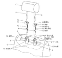
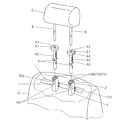
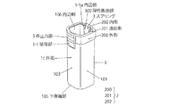
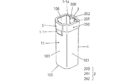
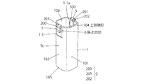
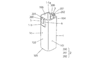
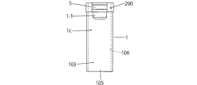
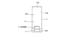
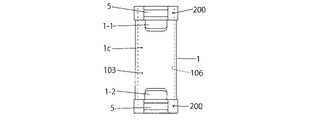
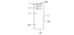
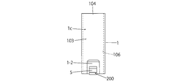
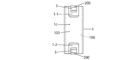
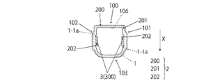
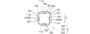
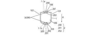
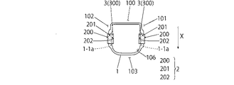
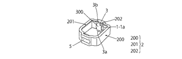
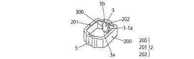
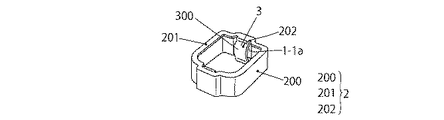
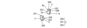
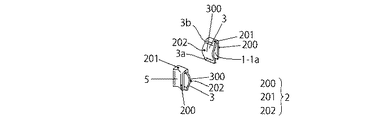
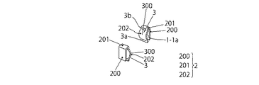
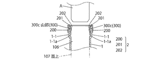
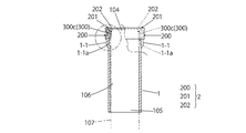
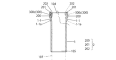
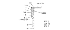
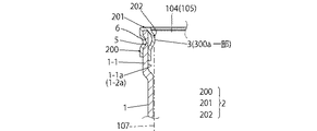
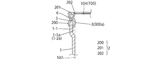
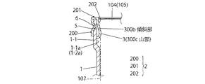
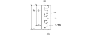
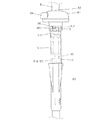
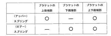
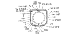
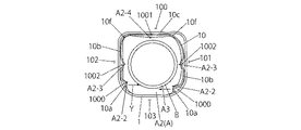
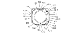
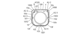
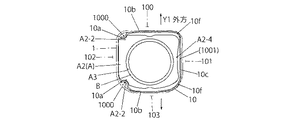
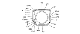
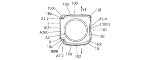
図中、1はサポートA(ヘッドレストサポート)を支持する角柱形状で四辺を有するブラケットで、このブラケット1は、シートDのアッパーフレームFに取付けられるクリンチ側1a(クリンチ加工で形成される凹凸の嵌合片側)、又は繋ぎ側1b(繋ぎ加工で形成される繋ぎ部側)でなる取付け側100と、この取付け側100より前方X(シートDの着座側)に向かって、略直角に立ち上げた(ブラケット1を平面視して)左右側102、101と、この左右側102、101間に設けた前面側103とでなり、加工装置で一体に形成する。そして、このブラケット1に、後述する角柱形状で四辺を有するベース体2、及び/又は、スプリング3を取付ける箇所、例えば、ブラケット1の上側端部104、及び/又は、下側端部105を拡径(拡大)し、拡径部1−1、1−2とする。この拡径部1−1、1−2には、ベース体2を取付ける(配設する)。そして、このベース体2は、前記拡径部1−1、1−2に準じた形状であり、ブラケット1の外面1cに添設される方形帯状(ブラケット1の角柱の形状に準ずる)の外側200と、ブラケット1の上下側端部104、105を跨る角柱形状の連結側201と、ブラケット1の拡径部1−1、1−2の内辺側1−1a、1−2aに至る内側202とで形成する。そして、この内側202には、対峙するようにしてスプリング3、3(対の例では、最初は併記するが、以後、単独の符号とする)が形成される。そして、このスプリング3に設けた弾性膨出部300が、このブラケット1の内辺側106と、同一か、又は内方に位置する構造である。尚、このベース体2の外側200には、図示した、横向きか、又は縦向きの一条、又は数条の線状か、また図示しないが、横向きか、又は縦向きの一個、又は数個の突起等でなる係止凸部5を形成する。この係止凸部5は、ブラケット1に設けた一条、数条等の係止凹部6に嵌合係止される。この係止凸部5と係止凹部6との凹凸関係は、一例であり、凸凹関係、又は多数個の凹凸関係等も可能である。尚、前記拡径部1−1、1−2の内辺側1−1a、1−2aの構造は、左右側102、101においても同じとする。
In the figure,
このベース体2は、方形形状に限らず、図6−2〜図6−2−2に示すように帯板(細幅板状)でも可能であり、このベース体2の内側には、スプリング3と弾性膨出部300を有する。その他の構造、形状は、前述の例に準ずる。
The
また、スプリング3の弾性膨出部300は、図8−1〜図9−1−4等に示すように、全体が弓型形状と、一部300aが弓型形状、傾斜部300bを備えた弓型形状、図示しないが、その他、全体が半球状、一部が半球状等の形状が考えられる。この中で、最適な例としては、撓み荷重に耐え得て、広く撓む形状で、例えば、全体が半球状、全体が弓型形状等の構造が好ましいと考えられる。
Further, as shown in FIGS. 8-1 to 9-1-4, etc., the elastic bulging
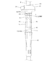
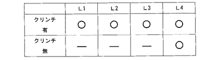
そして、前記ブラケット1に設けたクリンチ側1a、又は繋ぎ側1bは、ベース体2の縦方向の長さで調整することが望ましく、図10−1−1に示す如く、上側端部104にベース体2を設ける構造では、L3の長さとし、下側端部105にベース体2を設ける構造では、L2の長さとし、又は上下側端部104、105にベース体2を、それぞれ設ける構造では、L1の長さとした構造とする。このL1〜L3は、ベース体2の嵌着、ブラケット1の加工の簡易性、又は嵌着の信頼性の向上、等に有利性がある。尚、従来のブラケット1の構造をそのまま利用する、L4の構造も、慣習性と、機械の維持管理等の面から優位性がある。
The
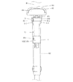
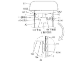
以上で説明したベース体2(枠形)付のスプリング3を、ブラケット1の四辺の上側端部104に配備する一例を説明すると、拡径部1−1の上方よりベース体2を套嵌すると、この拡径部1−1の外側にベース体2の外側200が添設され、また、ブラケット1の上端肉厚部に連結部201が被り、さらに、この拡径部1−1の内側にスプリング3の弾性膨出部300が添設されるものであり、図2−1と図3−1等に示されている。この状態において、係止凹凸部6、5の構造では、ブラケット1の係止凹部6に、ベース体2の係止凸部5が嵌入係止される。その他、凸凹関係も同様である。尚、この係止凹凸部6、5の構造を備えない構造では、ベース体2の上側端部104への圧嵌か、溶接等の固定手段を採用する。また、ブラケット1の下側端部105に配備する一例を説明すると、拡径部1−2の下方よりベース体2を套嵌すると、この拡径部1−2の外側にベース体2の外側200が添設され、また、ブラケット1の下端肉厚部に連結部201が被り、さらに、この拡径部1−2の内側にスプリング3の弾性膨出部300が添設されるものであり、図4−1−1に示されている。その他は、前述の例に準ずる。尚、ブラケット1の上下側端部104、105に配備する一例は、前記の組合せであり、説明は省略するが、図4−1〜図4−1−2、図13に示されている。その他は、前述の各例に準ずる。
An example in which the
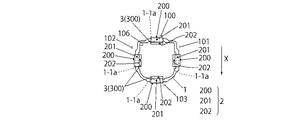
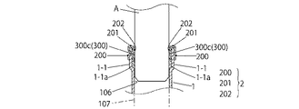
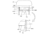
また、以上で説明したベース体2(帯板でなる)付のスプリング3を、ブラケット1の対峙する二辺の上側端部104に、それぞれ配備する一例(一辺での説明とする)を説明すると、拡径部1−1の上方よりベース体2を套嵌すると、この拡径部1−1の外側にベース体2の外側200が添設され、また、ブラケット1の上端肉厚部に連結部201が被り、さらに、この拡径部1−1の内側にスプリング3の弾性膨出部300が添設されるものであり、図2−2と図3−2等に示されている。この状態において、係止凹凸部6、5の構造では、ブラケット1の係止凹部6に、ベース体2の係止凸部5が嵌入係止される。その他、凸凹関係も同様である。尚、この係止凹凸部6、5の構造を備えない構造では、ベース体2の上側端部104への圧嵌か、溶接等の固定手段を採用する。また、ブラケット1の対峙する二辺の下側端部105に配備する一例を説明すると、拡径部1−2の下方よりベース体2を套嵌すると、この拡径部1−2の外側にベース体2の外側200が添設され、また、ブラケット1の下端肉厚部に連結部201が被り、さらに、この拡径部1−2の内側にスプリング3の弾性膨出部300が添設されるものであり、図4−2−1に示されている。その他は、前述の例に準ずる。尚、ブラケット1の上下側端部104、105に配備する一例は、前記の組合せであり、説明は省略するが、図4−2〜図4−2−2、図13に示されている。その他は、前述の各例に準ずる。
In addition, an example in which the
尚、ベース体2(枠形)付のスプリング3を、図5−1〜図5−1−2の如く、ブラケット1の四辺の上側端部104に配備するが、このスプリング3の弾性膨出部300を設ける位置は、この図5−1では、取付け側100と前面側103の二辺であり、また、図5−1−1では、左右側102、101の二辺であり、図5−1−2では、取付け側100と前面側103等の全てで四辺とする例がある。尚、図5−2〜図5−2−2の如く、ベース体2(帯板でなる)付のスプリング3においても、前述の図5−1〜図5−1−2の例に準ずる。
A
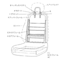
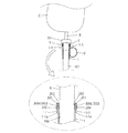
図中、Bはヘッドレストステー、Cはヘッドレスト、Dはシート、Fはブラケット1を取付けるアッパーフレームである。このアッパーフレームFと、サイドフレームG及びロアフレームHでフレームEを構成する。また、サポートAは、頭部A1と脚部A2並びに貫通孔A3と、操作釦A4と、複数の弾性手段A5(ブラケット1の内辺側106に圧接される)と、ブラケット1の切欠き部に係止される突片A6等を有する。
In the figure, B is a headrest stay, C is a headrest, D is a seat, and F is an upper frame to which the
また、図7−1〜図7−1−2に示した、第一実施例において、ベース体2付きスプリング3を、ブラケット1の上側端部104に配備し、サポートAを挿入する例では、図7−1の如く、弾性膨出部300の山部300cが、内辺側106と同じ面上107か、又は僅か突出するようにセットされる。この状態から、サポートAの周壁が、弾性膨出部300の山部300cを押圧しながら、順次、挿入される。この過程が、図7−1−1から図7−1−2の通りである。そして、セットされた状態においては、サポートAの周壁で、弾性膨出部300の山部300cを押圧することで、スプリング3の自由端側3aが伸びるとともに、その基端側3bには座屈圧力が付与され、かつ弾性膨出部300の山部300cの付勢力(反力)で、サポートAを弾性的に支持して、このサポートAとブラケット1との間のガタ防止を図るとともに、このサポートAから山部300cに対する反対方向の付勢力で、ブラケット1とサポートAとの間のガタ防止を図る構造である。従って、この弾性膨出部300の山部300cの付勢力と、前記反対方向の付勢力とを介して、このブラケット1及びサポートAとヘッドレストステーBとの総合的な、ガタ防止・衝撃緩和・ヘッドレスト・シート装置(ヘッドレストC、ヘッドレストステーB、又はブラケット1と、フレーム等)の故障回避「以下、同じ」等を図る(図9−1−1−〜図9−1−4、参照)。この際に、サポートAに設けた複数の弾性手段A5による協働のガタ防止も可能であり、極めて有効である(図12−1、図12−1−1、参照)。前述の如く、スプリング3の基端側3bに座屈圧力の付与がかかるので、この座屈圧力の付与が少ない形状が理想である。
Moreover, in the first embodiment shown in FIGS. 7-1 to 7-1-2, in the example in which the
尚、図16−1〜図21は、第三実施例におけるサポートAに、板材をコ字形状に折曲形成したスプリング10を設ける構造であり、このスプリング10は、両自由端側10a、10aと、この両自由端側10aにそれぞれ連なる対峙側10b、10bと、この対峙側10bを連結する連結側10cとで構成し、かつこの両自由端側10aに、その内方Yに向かって(以下、同じ)それぞれ凸部1000を、また、連結側10cに大きな凸部1001を形成する構造であり、かつ、このスプリング10の全体、殊に凸部1000、1001のブラケット1への挿入を容易にするために、その長手方向Zの下端10dに誘導片11を設ける。この誘導片11を設ける構造は、例えば、凸部1000、1001の下端面10eに一個、又は複数個設ける構造と、若しくは下端面10eの全部(スプリング10の全体か、その要部)に設ける構造がある。望ましくは、スプリング10の全体か、その要部等の方法が望ましい。
FIGS. 16-1 to 21 show a structure in which a
そして、この図例では、サポートAの脚部A2の上端部A2−1に、このスプリング10の凸部1000、1001の形状に対応する凹部A2−2と、A2−4が、又は捲装時にスプリング10を凹設するために凹部A2−3を形成するか、又は、必要により、コ字形状に対応する溝部A2−5をコ字形状に設けることも可能である。このスプリング10を、サポートAに捲装した後、このサポートAの脚部A2を、ブラケット1に挿入すると、前記凹部A2−3には、スプリング10の両凸部1000の脚部A2の両凸部A2−2への係止と、対峙側10bと、凸部1001及び繋ぎ部10fがブラケット1の内辺側で押圧されて、この対峙側10bが撓むことで、図示の如く、この対峙側10bの真中が凸部1002となり、係入される。尚、この凸部1002、及び/又は、凸部A2−4の双方、又は一方を省略することも可能である。
In this example, the upper end portion A2-1 of the leg portion A2 of the support A has the concave portions A2-2 and A2-4 corresponding to the shapes of the
このスプリング10は、図16−1〜図16−1−3の如く、サポートAの脚部A2(脚部A2とする)の何れの方向からも差込みできる(脚部A2にそれぞれの形態で捲装(設けると同意語)可能である)。従って、平面視して、向かって、左右方向の何れかと、上下方向の何れかであり、三方向に捲装できる。そして、スプリング10は、脚部A2に捲装した際、その各対峙側10bは外方Y1に向かって弓状に膨出する。また、この各対峙側10bと連結側10cとの繋ぎ部10fも同様に膨出する。この膨出箇所は、後述するように、ブラケット1に挿入した際に、弾性機能を発揮する。
The
例えば、図16−1において、脚部A2の上端部A2−1にスプリング10を捲装する際に、溝部A2−5を目安として、スプリング10の自由端側10aを拡開しながら差込み、脚部A2の凹部A2−2に到り、かつ連結側10cを、その凹部A2−4に添設すると、スプリング10の凸部1000、1002が、脚部A2のそれぞれの凹部A2−2〜A2−4に、係合されるとともに、前記各対峙側10b、及び/又は、繋ぎ部10fが、脚部A2の外側から離間(膨出)し、空間が形成される(各例も同じで、図示あり)とともに、付勢力を形成される。そして、この膨出した各対峙側10b、及び/又は、繋ぎ部10fを有するスプリング10付きの脚部A2を、ブラケット1に挿入する。この際に、誘導片11を利用して、差込むことで、容易に挿入できる。また、この各対峙側10b、及び/又は、繋ぎ部10fが圧着されて弾着支持されるとともに、サポートA、及び/又は、ヘッドレストステーB・ヘッドレストCに対する緩衝効果ができる。尚、この誘導片11は、脚部A2に弾着支持された際に、この脚部A2の突片A2−6で支持される。この突片A2−6は、前記溝部A2−5を設けない構造に有効である(図19、図20参照)。
For example, in FIG. 16A, when the
尚、前記スプリング10を、脚部A2の外側に弾着支持し、ブラケット1に挿入する際に、このスプリング10の各対峙側10bと、繋ぎ部10fが、ブラケット1の内辺側106に押圧される。この押圧で、各対峙側10bが内方に撓み、かつ脚部A2の凹部A2−3に陥没し、凸部1002が形成されることもあり得る(図16−1〜図16−1−3参照)。この例では、各対峙側10bが二山に区画される(二山の膨出形状となる)ことで、前記緩衝効果がより高くなると考えられる。また、スプリング10を、脚部A2に弾着支持する際に、この脚部A2に凹部A2−3を設けない構造では、各対峙側10bが一山となる(一山の膨出形状となる)。従って、その緩衝効果も期待できる(図20、21参照)。尚、図示しないが、スプリング10の捲装方向に、また、脚部A2の外側の横断方向に、前記の凸部1000、1002と、凹部A2−2〜A2−4を、一条乃至数条設けることも可能である。
When the
図22は、前記第一実施例における、ブラケット1に設けたスプリング3の付勢力で、ヘッドレストC、ヘッドレストステーBが安定的で、かつ適宜の弾性を持って装着されている状態で、頭部を保護していることと、落着いた状態での乗車が保障されている。次に、図23においては、ヘッドレストC、ヘッドレストステーBに衝撃が付加された状態において(前突)、スプリング3の付勢力で、このヘッドレストC、ヘッドレストステーBが頭部の衝撃を受止め、この衝撃緩和を図りつつ、保護が可能な状況を示している。尚、図示しないが、例えば、後突、又は乗車時も略同じと考えられる。
FIG. 22 shows the urging force of the
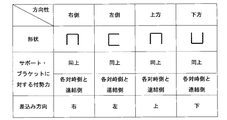
そして、図24は、第三実施例のスプリング10の形状と、差込み方向と、その付勢力の方向等を示した図表であり、好ましい一例であり限定されない。
FIG. 24 is a chart showing the shape of the
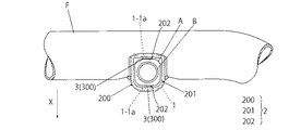
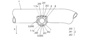
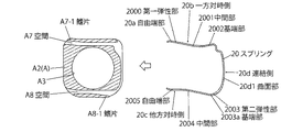
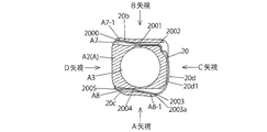
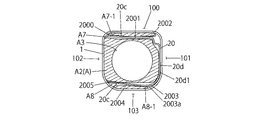
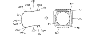
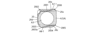
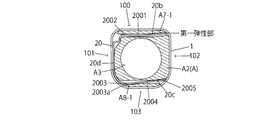
また、図25−1〜図27−3は、第四実施例におけるサポートAに、板材をコ字形状に折曲形成したスプリング20を設ける構造であり、このスプリング20は、一方対峙側20bと、他方対峙側20cと、この一方対峙側20bと、他方対峙側20cを繋ぐ連結側20dとで構成される。そして、この一方対峙側20bの構造は、その自由端部20aとなる第一弾性部2000を設けるとともに、この第一弾性部2000に繋がり、かつ内側(サポートAの内側)に凹設する中間部2001と、また、連結側20dに至る基端部2002とでなる。また、この他方対峙側20cの構造は、前記コ字形状の連結側20dを基端として放射方向に膨出し、かつ基端部2003aとなる第二弾性部2003と、内側に凹設する中間部2004を経由して延設した自由端部2005とでなる。尚、連結側20dは、曲面部20d1を有しており、この曲面部20d1は弾性機能を備えている。
FIGS. 25-1 to 27-3 show a structure in which a
そして、このスプリング20を、サポートAに形成した差込み空間A7、A8に差込み、また、望ましくは溝部A2−5に係入する。この一例では、空間A7の差込み端部に鰭片A7−1を備えている。また、空間A8の差込み部に鰭片A8−1を備えている。従って、この空間A7、A8に、スプリング20を差込み、この空間A7、A8に、中間部2001、2004が入り、かつ連結側20dが溝部A2−5に係入される。この時点で、図25−2、図27−2に示すように、第一弾性部2000が、鰭片A7−1を放射方向に拡開するとともに、第二弾性部2003が、鰭片A8−1を放射方向に拡開するとともに、この拡開に、空間A7、A8に差込まれた、中間部2001、2004の反発力を加担する。
And this
この鰭片A7−1と、鰭片A8−1と、スプリング20の第一弾性部2000と、第二弾性部2003が共に放射方向に拡開した状態で、誘導片2006を利用してブラケット1の内辺側106に差込む。この差込みで、鰭片A7−1と、スプリング20の第一弾性部2000が押圧、差込まれることで、ブラケット1の取付け側100(クリンチ側1a又は繋ぎ側1b)に弾着支持されるとともに、鰭片A8−1と、スプリング20の第二弾性部2003が押圧、差込まれることで、ブラケット1の前面側103に弾着支持される。この弾着支持を利用して、前述の如く、ガタ防止と、このヘッドレストC、ヘッドレストステーBが頭部の衝撃を受止め、この衝撃緩和を図りつつ、保護が可能な構造である。その他は、前述の各実施例に準ずる。そして、連結側20dに曲面部20d1を設ける構造では、ブラケット1の左右側102、101に弾着支持されるので、有意義である。
With the flange piece A7-1, the flange piece A8-1, the first
尚、前記誘導片2006は、この一方・他方対峙側20b、20cか、この連結側20dの何れか一箇所か、又は複数箇所に、スプリング20の長手方向Zの下端に下向きに設ける。この誘導片2006は、一片、又は複数片設ける。その他の構造は、第三実施例に準ずる。
The guide piece 2006 is provided downward at the lower end in the longitudinal direction Z of the
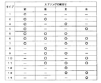
そして、図28は、第四実施例のブラケット1とスプリング20との組合せの各一例を示した図表であり、この図表の如く、例えば、14例が可能である。但し、一方対峙側20bと他方対峙側20cの単独構造では、このスプリング20の基端部2002、2003aに係止部か、連結側20dを設けることが望ましい。また、このスプリング20の差込み方向は、図25−1と図27−1の如く、左右側の図例に限定されず、この図において、上下側においても可能である。
FIG. 28 is a chart showing an example of each combination of the
また、図29は、従来のヘッドレスト装置(図示せず、ヘッドレスト、ヘッドレストステーと、サポート、並びにブラケット)、及びシートバックと、本発明のヘッドレスト装置(ヘッドレストC、ヘッドレストステーBと、サポートA、並びにブラケット1)、及びシートバック)との撓み量、撓み発生時間との関係を示した表であり、本発明では、時間差で衝撃緩衝(吸収)効果が期待できることで、安全性と、ムチ打ち等の怪我防止に役立つこと、また、シートDの緩衝装置を付加することで、緩衝緩和効果と、前述の怪我防止等に有効である。 29 shows a conventional headrest device (not shown, headrest, headrest stay, support, and bracket), a seat back, a headrest device of the present invention (headrest C, headrest stay B, support A, and It is the table | surface which showed the relationship with the deflection amount with a bracket 1) and a seat back | bag, and bending generation | occurrence | production time, and in this invention, since an impact buffering (absorption) effect can be anticipated with a time lag, safety, a whip, etc. This is useful for prevention of injury, and by adding a buffer device for the sheet D, it is effective for buffer relaxation effect and prevention of the above-mentioned injury.
1 ブラケット
1a クリンチ側
1b 繋ぎ側
1c 外面
1−1 拡径部
1−1a 内辺側
1−2 拡径部
1−2a 内辺側
100 取付け側
101 右側
102 左側
103 前面側
104 上側端部
105 下側端部
106 内辺側
107 面上
2 ベース体
200 外側
201 連結側
202 内側
3 スプリング
3a 自由端側
3b 基端側
300 弾性膨出部
300a 一部
300b 傾斜部
300c 山部
5 係止凸部
6 係止凹部
10 スプリング
10a 自由端側
10b 対峙側
10c 連結側
10d 下端
10e 下端面
10f 繋ぎ部
1000 凸部
1001 凸部
1002 凸部
11 誘導片
20 スプリング
20a 自由端部
20b 一方対峙側
20c 他方対峙側
20d 連結側
20d1 曲面部
2000 第一弾性部
2001 中間部
2002 基端部
2003 第二弾性部
2003a 基端部
2004 中間部
2005 自由端部
2006 誘導片
A サポート
A1 頭部
A2 脚部
A2−1 上端部
A2−2 凹部
A2−3 凹部
A2−4 凹部
A2−5 溝部
A2−6 突片
A3 貫通孔
A4 操作釦
A5 弾性手段
A6 突片
A7 空間
A7−1 鰭片
A8 空間
A8−1 鰭片
B ヘッドレストステー
C ヘッドレスト
D シート
E フレーム
F アッパーフレーム
G サイドフレーム
H ロアフレーム
X 前方
Y 内方
Y1 外方
Z 長手方向
1 Bracket
1a Clinch side
1b Connecting side
1c outer surface
1-1 Expanded part
1-1a Inner side
1-2 Expanded part
1-2a Inner side
100 Mounting side
101 right
102 left side
103 Front side
104 Upper edge
105 Lower edge
106 Inner side
107 face up
2 Base body
200 outside
201 Connection side
202 inside
3 Spring
3a Free end side
3b Base end side
300 Elastic bulge
300a part
300b Inclined part
300c Yamabe
5 Locking projection
6 Locking recess
10 Spring
10a Free end side
10b Opposite side
10c Connection side
10d bottom
10e bottom edge
10f connecting part
1000 convex
1001 Convex
1002 Convex
11 Guide piece
20 Spring
20a Free end
20b On the other side
20c On the other side
20d connection side
20d1 curved surface
2000 First elastic part
2001 Middle section
2002 Base end
2003 Second elastic part
2003a Base end
2004 middle part
2005 Free end
2006 Guide piece
A Support
A1 head
A2 leg
A2-1 Upper end
A2-2 Recess
A2-3 Recess
A2-4 recess
A2-5 Groove
A2-6 Projection
A3 Through hole
A4 operation button
A5 Elastic means
A6 protrusion
A7 space
A7-1 Strip
A8 space
A8-1 strip
B Headrest stay
C headrest
D sheet
E frame
F Upper frame
G side frame
H Lower frame
X forward
Y inward
Y1 outside
Z Longitudinal direction
Claims (21)
このブラケットの対峙方向に、スプリングを配設し、このスプリングに設けた弾性膨出部が、このブラケットの内辺側と、同一か、又は内方に位置する構成としたサポートの支持構造。 A support support structure composed of a support and a prism-shaped bracket that supports the support and is attached to a seat frame,
A support support structure in which a spring is disposed in the opposite direction of the bracket, and an elastic bulge provided on the spring is located on the same side as or on the inner side of the bracket.
前記ブラケットの対峙方向は、このブラケットの取付け側と前面側、又は左右側とする構成としたサポートの支持構造。 The support structure according to claim 1,
A support support structure in which the opposite direction of the bracket is configured to be the mounting side and the front side or the left and right sides of the bracket.
前記ブラケットの上側端部か、下側端部、又は上下端部の一部を、拡径して拡径部を形成し、この拡径部に、前記スプリングを配設する構成としたサポートの支持構造。 The support structure according to claim 1,
The support has a configuration in which the upper end portion, the lower end portion, or a part of the upper and lower end portions of the bracket is enlarged to form an enlarged diameter portion, and the spring is disposed in the enlarged diameter portion. Support structure.
前記スプリングは、ブラケットに固定されるベース体の縦方向の一面側に立設する構造であり、このベース体の係止凸部を、前記ブラケットの拡径部の外側に設けた係止凹部に係止するとともに、このベース体を、前記ブラケットの内側に至らしめ、かつこの内側に前記スプリングを配設する構成としたサポートの支持構造。 The support structure according to claim 1,
The spring is configured to stand on one side in the vertical direction of the base body fixed to the bracket, and the locking projection of the base body is formed into a locking recess provided outside the enlarged diameter portion of the bracket. A support support structure in which the base body is brought to the inside of the bracket and the spring is disposed inside the bracket while locking.
前記ブラケットのフレームの取付け側には、クリンチ加工による凹凸の嵌合片を形成する構成としたサポートの支持構造。 The support structure according to claim 1,
A support support structure having a structure in which concave and convex fitting pieces are formed by clinching on a mounting side of the bracket frame.
前記ブラケットのフレームの取付け側には、繋ぎ加工による線状の繋ぎ部を形成する構成としたサポートの支持構造。 The support structure according to claim 1,
A support support structure having a configuration in which a linear connecting portion is formed by connecting processing on an attachment side of the frame of the bracket.
前記ブラケットに、前記ベース体を配備した構造において、このベース体とスプリングを配備しない箇所に、前記クリンチ加工による凹凸の嵌合片を形成する構成としたサポートの支持構造。 A support support structure according to claim 5,
A support support structure in which a concave and convex fitting piece is formed by clinching in a place where the base body and the spring are not provided in a structure where the base body is provided on the bracket.
前記ベース体に、横向き、又は縦向きによる係止凸部を形成する構成としたサポートの支持構造。 A support support structure according to claim 4,
A support support structure in which the base body is formed with a locking protrusion in a horizontal direction or a vertical direction.
前記スプリングは、半円弧状か、弓型形状、擬似弓型形状か、又は波々形状とする構成としたサポートの支持構造。 The support structure according to claim 1,
The support structure of the support, wherein the spring has a semicircular arc shape, an arc shape, a pseudo arc shape, or a wave shape.
前記スプリングは、正面視して、細幅板状とする構成としたサポートの支持構造。 The support structure according to claim 1,
The support is a support structure in which the spring has a narrow plate shape when viewed from the front.
前記ブラケットの取付け側、左右側、又は前面側の全側に、前記スプリングを配設する構成としたサポートの支持構造。 The support structure according to claim 1,
A support support structure in which the spring is arranged on all sides of the bracket mounting side, left and right side, or front side.
前記ブラケットの取付け側と前面側、又は左右側の何れかの側に係止凹部を形成し、この係止凹部に、前記ベース体に設けた係止凸部を係止し、また、このベース体の連結側を、前記ブラケットの端側を迂回し、このベース体の内側にスプリングが設けられる構成としたサポートの支持構造。 A support support structure according to claim 4,
A locking recess is formed on either the mounting side and the front surface side or the left and right sides of the bracket, and a locking projection provided on the base body is locked in the locking recess. A support support structure in which a connecting side of the body bypasses the end side of the bracket and a spring is provided inside the base body.
前記ブラケットの取付け側、左右側、又は前面側の全側に係止凹部を形成し、この係止凹部に、前記ベース体に設けた係止凸部を係止し、また、このベース体の連結側を、前記ブラケットの端側を迂回し、このベース体の内側にスプリングが設けられる構成としたサポートの支持構造。 The support support structure according to claim 11,
A locking recess is formed on the mounting side, the left and right sides or the front side of the bracket, and a locking protrusion provided on the base body is locked in the locking recess. A support support structure in which the connecting side is configured to bypass the end side of the bracket and to have a spring provided inside the base body.
前記ベース体は、その外側が細幅の平板状で、その内側が細幅の前記スプリングである構成としたサポートの支持構造。 A support support structure according to claim 4,
A support support structure in which the base body has a narrow flat plate shape on the outside and the narrow spring on the inside.
このサポートにスプリングを捲装し、このスプリングを圧着して前記ブラケットに挿入し、このスプリングで、前記ブラケットに前記サポートを弾着可能とする構成としたサポートの支持構造。 A support support structure composed of a support and a prism-shaped bracket that supports the support and is attached to a seat frame,
A support support structure in which a spring is mounted on the support, the spring is crimped and inserted into the bracket, and the support can be elastically attached to the bracket with the spring.
前記スプリングは、前記サポートの長手方向を横断するように捲装するとともに、このスプリングの長手方向の下側に誘導片を設け、この誘導片の先端部が、前記スプリングの外側より内方に位置する構成としたサポートの支持構造。 A support support structure according to claim 15,
The spring is equipped so as to cross the longitudinal direction of the support, and a guide piece is provided on the lower side of the spring in the longitudinal direction, and the leading end of the guide piece is positioned inward from the outside of the spring. Support structure with support.
このスプリングには、内方に向かって陥没した凸部を一個、又は複数個設ける構成とし、この一個、又は複数個の凸部に対応する凹部を、前記サポートの外側に、一個、又は複数個設ける構成としたサポートの支持構造。 A support support structure according to claim 15,
The spring has a configuration in which one or a plurality of convex portions recessed inward are provided, and one or a plurality of concave portions corresponding to the one or the plurality of convex portions are provided on the outside of the support. Support structure for the support that is provided.
このサポートの横断方向に開設した空間にスプリングを挿設し、このスプリングで、このサポートの鰭片を放射方向に膨出するとともに、この鰭片の膨出を、前記ブラケットに圧着して挿入し、この鰭片とスプリングで、前記ブラケットに前記サポートを弾着可能とする構成としたサポートの支持構造。 A support support structure composed of a support and a prism-shaped bracket that supports the support and is attached to a seat frame,
A spring is inserted into the space opened in the transverse direction of the support, and the flange of the support is swelled in the radial direction with this spring, and the bulge of the flange is inserted into the bracket by being crimped. The support support structure is configured such that the support can be elastically attached to the bracket by the flange and the spring.
前記スプリングは、横断方向において、コ字形状であって、その一方対峙側の自由端部を、放射方向に膨出することで第一弾性部とするとともに、その他方対峙側の基端部を、放射方向に膨出することで第二弾性部とし、この第一・第二弾性部を、前記ブラケットに圧着して挿入し、この鰭片とスプリングで、前記ブラケットに前記サポートを弾着可能とする構成としたサポートの支持構造。 A support support structure according to claim 18, comprising:
The spring is U-shaped in the transverse direction, and the free end portion on one side of the spring is swelled in the radial direction to form a first elastic portion, and the base end portion on the other side is on the other side. By bulging in the radial direction, it becomes a second elastic part, and the first and second elastic parts can be crimped and inserted into the bracket, and the support can be elastically attached to the bracket with this flange and spring. Support structure with support.
前記コ字形状のスプリングは、前記一方・他方対峙側と、この一方・他方対峙側を連結する連結側とで構成し、かつこの一方・他方対峙側と、この連結側の何れか一箇所か、又は複数箇所に、下向きの一片、又は複数片の誘導片を設ける構成としたサポートの支持構造。 A support support structure according to claim 18, comprising:
The U-shaped spring is composed of the one / other opposing side and a connecting side that connects the one / other opposing side, and the one / other opposing side is either one of the connecting sides. Or a support support structure in which a downwardly facing piece or a plurality of guide pieces are provided at a plurality of locations.
前記一方対峙側に設けた第一弾性部は、内側に凹設する中間部を経由し、前記コ字形状の連結側に至る基端部を有する構造とするとともに、前記他方対峙側に設けられた第二弾性部は、前記コ字形状の連結側を基端として設け、かつその一端には、内側に凹設する中間部を経由して延設した自由端部を備える構成としたサポートの支持構造。 A support support structure according to claim 18, comprising:
The first elastic portion provided on the one opposite side has a structure having a base end portion reaching the U-shaped connecting side via an intermediate portion recessed inward and provided on the other opposite side. The second elastic portion is provided with the U-shaped connecting side as a base end, and at one end of the support, a free end portion extending through an intermediate portion recessed inward is provided. Support structure.
Priority Applications (1)
| Application Number | Priority Date | Filing Date | Title |
|---|---|---|---|
| JP2011006378A JP5669588B2 (en) | 2010-12-22 | 2011-01-14 | Support support structure |
Applications Claiming Priority (3)
| Application Number | Priority Date | Filing Date | Title |
|---|---|---|---|
| JP2010286575 | 2010-12-22 | ||
| JP2010286575 | 2010-12-22 | ||
| JP2011006378A JP5669588B2 (en) | 2010-12-22 | 2011-01-14 | Support support structure |
Publications (2)
| Publication Number | Publication Date |
|---|---|
| JP2012144232A true JP2012144232A (en) | 2012-08-02 |
| JP5669588B2 JP5669588B2 (en) | 2015-02-12 |
Family
ID=46788261
Family Applications (1)
| Application Number | Title | Priority Date | Filing Date |
|---|---|---|---|
| JP2011006378A Active JP5669588B2 (en) | 2010-12-22 | 2011-01-14 | Support support structure |
Country Status (1)
| Country | Link |
|---|---|
| JP (1) | JP5669588B2 (en) |
Cited By (1)
| Publication number | Priority date | Publication date | Assignee | Title |
|---|---|---|---|---|
| JP2016101776A (en) * | 2014-11-27 | 2016-06-02 | 株式会社パイオラックス | Support equipment for headrest |
Citations (5)
| Publication number | Priority date | Publication date | Assignee | Title |
|---|---|---|---|---|
| JPH0219347U (en) * | 1988-07-26 | 1990-02-08 | ||
| JPH0233659U (en) * | 1988-08-24 | 1990-03-02 | ||
| JP2002079333A (en) * | 2000-07-04 | 2002-03-19 | Nippon Tekunika Kk | Metal cylinder and metal bracket |
| JP2006082771A (en) * | 2004-09-17 | 2006-03-30 | Nhk Spring Co Ltd | Vehicle seat |
| JP2011207335A (en) * | 2010-03-30 | 2011-10-20 | Ts Tech Co Ltd | Vehicle seat |
-
2011
- 2011-01-14 JP JP2011006378A patent/JP5669588B2/en active Active
Patent Citations (5)
| Publication number | Priority date | Publication date | Assignee | Title |
|---|---|---|---|---|
| JPH0219347U (en) * | 1988-07-26 | 1990-02-08 | ||
| JPH0233659U (en) * | 1988-08-24 | 1990-03-02 | ||
| JP2002079333A (en) * | 2000-07-04 | 2002-03-19 | Nippon Tekunika Kk | Metal cylinder and metal bracket |
| JP2006082771A (en) * | 2004-09-17 | 2006-03-30 | Nhk Spring Co Ltd | Vehicle seat |
| JP2011207335A (en) * | 2010-03-30 | 2011-10-20 | Ts Tech Co Ltd | Vehicle seat |
Cited By (1)
| Publication number | Priority date | Publication date | Assignee | Title |
|---|---|---|---|---|
| JP2016101776A (en) * | 2014-11-27 | 2016-06-02 | 株式会社パイオラックス | Support equipment for headrest |
Also Published As
| Publication number | Publication date |
|---|---|
| JP5669588B2 (en) | 2015-02-12 |
Similar Documents
| Publication | Publication Date | Title |
|---|---|---|
| JP4860932B2 (en) | Shock-absorbing automotive seat | |
| JP5338813B2 (en) | Folding seat | |
| CN104781105B (en) | Auto use chair | |
| JP5296747B2 (en) | Vehicle seat | |
| EP2894060B1 (en) | Vehicle seat | |
| JP2011511738A (en) | Vehicle seat tether | |
| WO2014167638A1 (en) | Vehicle seat and seat frame for same | |
| JP2009189486A (en) | Vehicle seat headrest | |
| CN104869867B (en) | car seat | |
| JP5669588B2 (en) | Support support structure | |
| JP5880309B2 (en) | Vehicle seat | |
| JP5535690B2 (en) | Seat back frame structure | |
| JP6718125B2 (en) | Vehicle seat | |
| JP2010089581A (en) | Vehicular seat | |
| JP5487175B2 (en) | Shock-absorbing automotive seat | |
| JP5677562B2 (en) | Shock-absorbing automotive seat | |
| JP2017081565A (en) | Seat frame for vehicle seat | |
| JP6096963B2 (en) | Seat frame for vehicle seat | |
| JP5645744B2 (en) | Knee protector structure for vehicles | |
| JP5550972B2 (en) | Seat back frame structure | |
| JP2008080971A (en) | Tank arrangement structure | |
| KR102776302B1 (en) | Assist handle mounting bracket | |
| JP2006027575A (en) | Vehicle headrest | |
| JP2005287765A (en) | Headrest frame, and headrest with the headrest frame | |
| JP2012171610A (en) | Seat for automobile |
Legal Events
| Date | Code | Title | Description |
|---|---|---|---|
| A621 | Written request for application examination |
Free format text: JAPANESE INTERMEDIATE CODE: A621 Effective date: 20131224 |
|
| A131 | Notification of reasons for refusal |
Free format text: JAPANESE INTERMEDIATE CODE: A131 Effective date: 20141009 |
|
| A521 | Request for written amendment filed |
Free format text: JAPANESE INTERMEDIATE CODE: A523 Effective date: 20141022 |
|
| A131 | Notification of reasons for refusal |
Free format text: JAPANESE INTERMEDIATE CODE: A131 Effective date: 20141111 |
|
| A521 | Request for written amendment filed |
Free format text: JAPANESE INTERMEDIATE CODE: A523 Effective date: 20141113 |
|
| TRDD | Decision of grant or rejection written | ||
| A01 | Written decision to grant a patent or to grant a registration (utility model) |
Free format text: JAPANESE INTERMEDIATE CODE: A01 Effective date: 20141202 |
|
| A61 | First payment of annual fees (during grant procedure) |
Free format text: JAPANESE INTERMEDIATE CODE: A61 Effective date: 20141216 |
|
| R150 | Certificate of patent or registration of utility model |
Ref document number: 5669588 Country of ref document: JP Free format text: JAPANESE INTERMEDIATE CODE: R150 |
|
| R250 | Receipt of annual fees |
Free format text: JAPANESE INTERMEDIATE CODE: R250 |
|
| R250 | Receipt of annual fees |
Free format text: JAPANESE INTERMEDIATE CODE: R250 |
|
| R250 | Receipt of annual fees |
Free format text: JAPANESE INTERMEDIATE CODE: R250 |
|
| R250 | Receipt of annual fees |
Free format text: JAPANESE INTERMEDIATE CODE: R250 |
|
| R250 | Receipt of annual fees |
Free format text: JAPANESE INTERMEDIATE CODE: R250 |
|
| R250 | Receipt of annual fees |
Free format text: JAPANESE INTERMEDIATE CODE: R250 |
|
| R250 | Receipt of annual fees |
Free format text: JAPANESE INTERMEDIATE CODE: R250 |
|
| R250 | Receipt of annual fees |
Free format text: JAPANESE INTERMEDIATE CODE: R250 |