JP2012144198A - Steering device of vehicle - Google Patents
Steering device of vehicle Download PDFInfo
- Publication number
- JP2012144198A JP2012144198A JP2011005350A JP2011005350A JP2012144198A JP 2012144198 A JP2012144198 A JP 2012144198A JP 2011005350 A JP2011005350 A JP 2011005350A JP 2011005350 A JP2011005350 A JP 2011005350A JP 2012144198 A JP2012144198 A JP 2012144198A
- Authority
- JP
- Japan
- Prior art keywords
- operating device
- hand
- operating
- transmission
- interlocking
- Prior art date
- Legal status (The legal status is an assumption and is not a legal conclusion. Google has not performed a legal analysis and makes no representation as to the accuracy of the status listed.)
- Granted
Links
Images

Landscapes
- Automatic Cycles, And Cycles In General (AREA)
- Non-Deflectable Wheels, Steering Of Trailers, Or Other Steering (AREA)
- Flexible Shafts (AREA)
- Friction Gearing (AREA)
Abstract
【課題】操舵のために運転者にかかる負担を軽減することのできる車両の操舵装置を提供する。
【解決手段】この操舵装置1には、右後輪15の回転速度および左後輪16の回転速度を変速比に応じた大きさに変更する無段変速装置50が設けられている。また操作装置60には、この無段変速装置50内のねじ機構を動作させて変速比を変更するドラム61が設けられている。また、右後輪15および左後輪16が直進するときの変速比を直進変速比とし、右後輪15および左後輪16が旋回するときの変速比を旋回変速比とし、変速比が直進変速比のときの無段変速装置50の動作状態を直進動作状態とし、変速比が旋回変速比のときの無段変速装置50の動作状態を旋回動作状態として、無段変速装置50の動作状態を旋回動作状態から直進動作状態に復帰させる復帰装置70が設けられている。
【選択図】図1A vehicle steering apparatus capable of reducing a burden on a driver for steering is provided.
The steering device is provided with a continuously variable transmission that changes the rotational speed of a right rear wheel and the rotational speed of a left rear wheel to a magnitude corresponding to a gear ratio. Further, the operating device 60 is provided with a drum 61 that changes the gear ratio by operating the screw mechanism in the continuously variable transmission 50. Further, the speed ratio when the right rear wheel 15 and the left rear wheel 16 goes straight is defined as the straight speed ratio, and the speed ratio when the right rear wheel 15 and the left rear wheel 16 turns is the turning speed ratio. The operation state of the continuously variable transmission 50 when the transmission ratio is the straight running operation state and the operation state of the continuously variable transmission 50 when the transmission ratio is the turning gear ratio is the turning operation state. A return device 70 is provided for returning the vehicle from the turning operation state to the straight traveling operation state.
[Selection] Figure 1
Description
本発明は、右駆動輪の回転速度および左駆動輪の回転速度を変速比に応じた大きさに変更する変速装置が設けられた車両の操舵装置に関する。 The present invention relates to a vehicle steering apparatus provided with a transmission that changes the rotation speed of a right drive wheel and the rotation speed of a left drive wheel to a magnitude corresponding to a transmission gear ratio.
特許文献1には、右後輪および左後輪の回転を制御する三輪自転車が開示されている。この三輪自転車は、1つの前輪および2つの後輪と、右後輪と左後輪との間に設けられたベベルギヤとを備えている。そして、このベベルギヤにより右後輪の回転速度と左後輪の回転速度とが互いに異なるものに変更される。
ところが、特許文献1の三輪自転車は、前輪に直結されたハンドルを手で操作することにより操舵角を変更するものであるため、例えば、上肢不自由者のようにハンドルを操作することが困難な者においては同自転車の操舵にかかる負担が大きい。
However, since the three-wheeled bicycle of
本発明はこのような課題に鑑みてなされたものであり、その目的は、操舵のために運転者にかかる負担を軽減することのできる車両の操舵装置を提供することにある。 The present invention has been made in view of such problems, and an object of the present invention is to provide a vehicle steering apparatus that can reduce the burden on the driver for steering.
上記目的を達成するための手段を以下に示す。
(1)請求項1に記載の発明は、右駆動輪の回転速度および左駆動輪の回転速度を変速比に応じた大きさに変更する変速装置が設けられていること、この変速装置内の機構を動作させて前記変速比を変更する変更部材が設けられていること、ならびに、車両が直進するときの前記変速比を直進変速比とし、車両が旋回するときの前記変速比を旋回変速比とし、前記変速比が前記直進変速比のときの前記変速装置の動作状態を直進動作状態とし、前記変速比が前記旋回変速比のときの前記変速装置の動作状態を旋回動作状態として、前記変速装置の動作状態を前記旋回動作状態から前記直進動作状態に復帰させる復帰装置が設けられていることを要旨としている。
Means for achieving the above object will be described below.
(1) The invention described in
この発明によれば、変速装置の変速比の変更により右駆動輪の回転速度と左駆動輪の回転速度とが互いに異なるものに変更されたときには、転舵輪の舵角が変更される。このため、転舵輪に連結されたハンドルの操作により同転舵輪の舵角を変更する構成が用いられる場合と比較して、操舵のために運転者にかかる負担を小さくすることができる。また、変速装置の動作状態を旋回動作状態から直進動作状態に復帰させる復帰装置が設けられているため、直進時の走行安定性が向上する。 According to the present invention, when the rotational speed of the right drive wheel and the rotational speed of the left drive wheel are changed to different ones by changing the speed ratio of the transmission, the steering angle of the steered wheels is changed. For this reason, compared with the case where the structure which changes the rudder angle of the steered wheel by operation of the steering wheel connected to the steered wheel is used, the burden on the driver for steering can be reduced. In addition, since a return device for returning the operation state of the transmission from the turning operation state to the straight operation state is provided, the running stability during the straight operation is improved.
(2)請求項2に記載の発明は、請求項1に記載の車両の操舵装置において、当該操舵装置には、前記変更部材を駆動する操作装置が設けられていること、この操作装置には、運転者により操作される操作部材と、この操作部材に入力された力により前記変更部材を駆動する接続部材とが設けられていること、ならびに、前記変速比が前記旋回変速比から前記直進変速比に向けて変化する前記変更部材の動作を復帰変速動作として、前記変更部材を同復帰変速動作させる力が前記復帰装置から前記接続部材に付与されることを要旨としている。
(2) The invention according to
この発明によれば、変更部材を復帰変速動作方向に動作させる力が復帰装置から接続部材に付与されることにより、変速装置の動作状態が旋回動作状態から直進動作状態に復帰する。また、復帰装置から接続部材に付与される力が運転者による操作部材の操作に対する反力として作用する。このため、操作部材の操作に対する反力が生じない場合と比較して、運転者が操作部材を操作するときの操作性が向上する。 According to the present invention, the operation state of the transmission device is returned from the turning operation state to the straight operation state by applying a force for operating the changing member in the return transmission operation direction from the return device to the connection member. Further, the force applied to the connection member from the return device acts as a reaction force against the operation of the operation member by the driver. For this reason, compared with the case where the reaction force with respect to operation of an operation member does not arise, the operativity when a driver operates an operation member improves.
(3)請求項3に記載の発明は、請求項2に記載の車両の操舵装置において、前記復帰装置には、前記接続部材に対して移動する相対移動部材と、前記接続部材に連動する連動部材と、この連動部材の移動方向において前記相対移動部材に対して前記連動部材とは反対側に設けられた弾性部材とが設けられていること、前記変更部材と前記操作部材との間においては前記連動部材および前記相対移動部材および前記弾性部材の順にこれらの構成要素が設けられていること、前記変速比が前記直進変速比から前記旋回変速比に向けて変化する前記変更部材の動作を旋回変速動作とし、前記連動部材が前記相対移動部材に接近する方向を接近方向とし、前記連動部材が前記相対移動部材から離間する方向を離間方向として、前記操作部材の操作により前記接続部材が前記接近方向に移動するとき、前記変更部材が前記旋回変速動作すること、ならびに、前記操作部材の操作により前記変速装置が前記旋回動作状態にあるとき、前記弾性部材の復元力により前記変更部材を前記復帰変速動作させる力が前記相対移動部材および前記連動部材を介して前記接続部材に付与されることを要旨としている。
(3) The invention according to claim 3 is the vehicle steering apparatus according to
この発明によれば、運転者が操作装置の操作部材を操作することにより接続部材が接近方向に移動するとき、接続部材、連動部材および相対移動部材が一体となり接近方向に移動するとともに弾性部材が相対移動部材との接触により変形する。そして、運転者が操作部材に加える力を緩めたことにともない弾性部材の復元力が操作部材に加えられる力を上回るときには、相対移動部材が弾性部材の復元力により離間方向に移動する。このとき、相対移動部材と連動部材とが互いに接触していることにより、弾性部材の復元力すなわち、変更部材を復帰変速動作させる力が相対移動部材および連動部材を介して接続部材に付与される。このため、変速装置の動作状態が旋回動作状態から直進動作状態に復帰する。 According to this invention, when the connecting member moves in the approaching direction by the driver operating the operating member of the operating device, the connecting member, the interlocking member, and the relative moving member move together in the approaching direction and the elastic member Deformation is caused by contact with the relative movement member. When the restoring force of the elastic member exceeds the force applied to the operating member as the driver loosens the force applied to the operating member, the relative movement member moves in the separation direction by the restoring force of the elastic member. At this time, since the relative movement member and the interlocking member are in contact with each other, the restoring force of the elastic member, that is, the force for causing the changing member to perform the return shifting operation is applied to the connection member via the relative movement member and the interlocking member. . For this reason, the operation state of the transmission returns from the turning operation state to the straight operation state.
(4)請求項4に記載の発明は、請求項3に記載の車両の操舵装置において、前記操作装置として、右手用操作装置および左手用操作装置が設けられていること、前記右手用操作装置の操作部材の操作により同操作装置の前記連動部材が前記接近方向に移動するとき、前記左手用操作装置において同操作装置の前記連動部材が前記離間方向に移動するとともに前記変更部材が前記旋回変速動作すること、前記左手用操作装置の操作部材の操作により同操作装置の前記連動部材が前記接近方向に移動するとき、前記右手用操作装置において同操作装置の前記連動部材が前記離間方向に移動するとともに前記変更部材が前記旋回変速動作すること、前記右手用操作装置の操作部材の操作により前記変速装置が前記旋回動作状態にあるとき、前記右手用操作装置の弾性部材の復元力により同操作装置において前記変更部材を前記復帰変速動作させる力が同操作装置の前記相対移動部材および前記連動部材を介して前記接続部材に付与されること、ならびに、前記左手用操作装置の操作部材の操作により前記変速装置が前記旋回動作状態にあるとき、前記左手用操作装置の弾性部材の復元力により同操作装置において前記変更部材を前記復帰変速動作させる力が同操作装置の前記相対移動部材および前記連動部材を介して前記接続部材に付与されることを要旨としている。 (4) The invention according to claim 4 is the vehicle steering device according to claim 3, wherein a right-hand operation device and a left-hand operation device are provided as the operation devices, and the right-hand operation device. When the interlocking member of the operating device is moved in the approaching direction by the operation of the operating member, the interlocking member of the operating device is moved in the separating direction in the left-hand operating device, and the changing member is When the interlocking member of the operating device moves in the approaching direction by operating the operating member of the left-hand operating device, the interlocking member of the operating device moves in the separating direction in the right-handed operating device. And when the speed change device is in the turning operation state by the operation of the operation member of the right-hand operation device, A force for causing the change member to perform the return shifting operation in the operating device by the restoring force of the elastic member of the operating device is applied to the connecting member via the relative moving member and the interlocking member of the operating device; and When the transmission device is in the turning operation state by operating the operation member of the left-hand operation device, the force for causing the change member to perform the return shift operation in the operation device by the restoring force of the elastic member of the left-hand operation device Is provided to the connection member via the relative movement member and the interlocking member of the operating device.
この発明によれば、運転者が右手用操作装置または左手用操作装置の操作部材を操作することにより右手用操作装置または左手用操作装置の接続部材が接近方向に移動するとき、接続部材、連動部材および相対移動部材が一体となり接近方向に移動するとともに弾性部材が相対移動部材との接触により変形する。そして、運転者が操作部材に加える力を緩めたことにともない弾性部材の復元力が操作部材に加えられる力を上回るときには、相対移動部材が弾性部材の復元力により離間方向に移動する。このとき、相対移動部材と連動部材とが互いに接触していることにより、弾性部材の復元力すなわち、変更部材を復帰変速動作させる力が相対移動部材および連動部材を介して接続部材に付与される。このため、変速装置の動作状態が旋回動作状態から直進動作状態に復帰する。 According to the present invention, when the driver operates the operation member of the right-hand operation device or the left-hand operation device, the connection member of the right-hand operation device or the left-hand operation device moves in the approaching direction. The member and the relative movement member move together in the approaching direction, and the elastic member is deformed by contact with the relative movement member. When the restoring force of the elastic member exceeds the force applied to the operating member as the driver loosens the force applied to the operating member, the relative movement member moves in the separation direction by the restoring force of the elastic member. At this time, since the relative movement member and the interlocking member are in contact with each other, the restoring force of the elastic member, that is, the force for causing the changing member to perform the return shifting operation is applied to the connection member via the relative movement member and the interlocking member. . For this reason, the operation state of the transmission returns from the turning operation state to the straight operation state.
(5)請求項5に記載の発明は、請求項2に記載の車両の操舵装置において、前記操作装置として、右手用操作装置および左手用操作装置が設けられていること、前記復帰装置には、前記接続部材に対して移動する相対移動部材と、前記接続部材に連動する連動部材と、この連動部材の移動方向において前記相対移動部材に対して前記連動部材とは反対側に設けられた弾性部材とが設けられていること、前記変更部材と前記操作部材との間においては前記弾性部材および前記相対移動部材および前記連動部材の順にこれらの構成要素が設けられていること、前記変速比が前記直進変速比から前記旋回変速比に向けて変化する前記変更部材の動作を旋回変速動作とし、前記連動部材が前記相対移動部材に接近する方向を接近方向とし、前記連動部材が前記相対移動部材から離間する方向を離間方向として、前記右手用操作装置の操作部材の操作により同操作装置の前記連動部材が前記離間方向に移動するとき、前記左手用操作装置において同操作装置の前記連動部材が前記接近方向に移動するとともに前記変更部材が前記旋回変速動作すること、前記左手用操作装置の操作部材の操作により同操作装置の前記連動部材が前記離間方向に移動するとき、前記右手用操作装置において同操作装置の前記連動部材が前記接近方向に移動するとともに前記変更部材が前記旋回変速動作すること、前記右手用操作装置の操作部材の操作により前記変速装置が前記旋回動作状態にあるとき、前記左手用操作装置の弾性部材の復元力により同操作装置において前記変更部材を前記復帰変速動作させる力が同操作装置の前記相対移動部材および前記連動部材を介して前記接続部材に付与されること、ならびに、前記左手用操作装置の操作部材の操作により前記変速装置が前記旋回動作状態にあるとき、前記右手用操作装置の弾性部材の復元力により同操作装置において前記変更部材を前記復帰変速動作させる力が同操作装置の前記相対移動部材および前記連動部材を介して前記接続部材に付与されることを要旨としている。 (5) According to a fifth aspect of the present invention, in the vehicle steering apparatus according to the second aspect, a right-handed operating device and a left-handed operating device are provided as the operating devices, and the return device includes A relative moving member that moves relative to the connecting member; an interlocking member that interlocks with the connecting member; and an elasticity provided on a side opposite to the interlocking member with respect to the relative moving member in a moving direction of the interlocking member. Members are provided, and between the change member and the operation member, these components are provided in the order of the elastic member, the relative movement member, and the interlocking member, and the gear ratio is An operation of the change member that changes from the straight speed ratio toward the turning speed ratio is a turning speed change operation, a direction in which the interlocking member approaches the relative movement member is an approaching direction, and the interlocking operation is performed. When the interlocking member of the operating device moves in the separating direction by the operation of the operating member of the right-hand operating device, the same operation is performed in the left-hand operating device. When the interlocking member of the device moves in the approaching direction and the changing member performs the turning speed change operation, and when the interlocking member of the operating device moves in the separating direction by operation of the operating member of the left-hand operating device In the right-hand operating device, the interlocking member of the operating device moves in the approaching direction and the changing member performs the turning speed change operation. The operation of the operating member of the right-hand operating device causes the speed change device to turn. When in the operating state, the return member performs the return shift operation in the operating device by the restoring force of the elastic member of the left-hand operating device. Is provided to the connection member via the relative movement member and the interlocking member of the operation device, and when the transmission is in the turning operation state by operation of the operation member of the left-hand operation device, A force for causing the changing member to perform the return speed change operation in the operating device by the restoring force of the elastic member of the right-hand operating device is applied to the connecting member via the relative movement member and the interlocking member of the operating device. Is the gist.
この発明によれば、運転者が右手用操作装置または左手用操作装置の操作部材を操作することにより右手用操作装置または左手用操作装置の接続部材が接近方向に移動するとき、接続部材、連動部材および相対移動部材が一体となり接近方向に移動するとともに弾性部材が相対移動部材との接触により変形する。そして、運転者が操作部材に加える力を緩めたことにともない弾性部材の復元力が操作部材に加えられる力を上回るときには、右手用操作装置および左手用操作装置の他方において相対移動部材が弾性部材の復元力により離間方向に移動する。このとき、相対移動部材と連動部材とが互いに接触していることにより、弾性部材の復元力すなわち、変更部材を復帰変速動作させる力が相対移動部材および連動部材を介して接続部材に付与される。このため、変速装置の動作状態が旋回動作状態から直進動作状態に復帰する。 According to the present invention, when the driver operates the operation member of the right-hand operation device or the left-hand operation device, the connection member of the right-hand operation device or the left-hand operation device moves in the approaching direction. The member and the relative movement member move together in the approaching direction, and the elastic member is deformed by contact with the relative movement member. When the restoring force of the elastic member exceeds the force applied to the operation member as the driver loosens the force applied to the operation member, the relative movement member is the elastic member in the other of the right-hand operation device and the left-hand operation device. It moves in the separation direction by the restoring force. At this time, since the relative movement member and the interlocking member are in contact with each other, the restoring force of the elastic member, that is, the force for causing the changing member to perform the return shifting operation is applied to the connection member via the relative movement member and the interlocking member. . For this reason, the operation state of the transmission returns from the turning operation state to the straight operation state.
(6)請求項6に記載の発明は、請求項4または5に記載の車両の操舵装置において、前記弾性部材においての前記連動部材側の端部である第1端部が前記相対移動部材に取り付けられていること、前記復帰装置には、前記接近方向および前記離間方向において相対的な移動が可能な第1ハウジングおよび第2ハウジングが設けられていること、ならびに、前記弾性部材においての前記連動部材側とは反対側の端部である第2端部が前記第2ハウジングに取り付けられていることを要旨としている。 (6) The invention according to claim 6 is the vehicle steering apparatus according to claim 4 or 5, wherein a first end portion which is an end portion on the interlocking member side of the elastic member is the relative movement member. Being attached, the return device being provided with a first housing and a second housing capable of relative movement in the approaching direction and the separating direction, and the interlocking in the elastic member The gist is that the second end, which is the end opposite to the member side, is attached to the second housing.
この発明によれば、第2ハウジングを第1ハウジングに対して接近方向または離間方向に移動させることにより、連動部材が相対移動部材に押し付けられていない状態においての弾性部材の長さ、すなわち弾性部材の予圧の大きさを変更することができる。弾性部材の予圧の大きさが変更されたときには、運転者による操作部材の操作に対する反力の大きさが変更されるため、運転者が操作部材に加える力に対する操作部材の動作量も変更される。 According to this invention, the length of the elastic member in a state where the interlocking member is not pressed against the relative movement member by moving the second housing in the approaching direction or the separation direction with respect to the first housing, that is, the elastic member The size of the preload can be changed. When the magnitude of the preload of the elastic member is changed, the magnitude of the reaction force against the operation of the operation member by the driver is changed, so that the operation amount of the operation member with respect to the force applied by the driver to the operation member is also changed. .
そして上記発明では、右手用操作装置および左手用操作装置において独立して上記弾性部材の長さを変更することができるため、例えば、当該操舵装置を搭載した車両において右旋回時の速度が左旋回時の速度よりも大きくなる場合には、右手用操作装置の弾性部材の予圧を左手用操作装置の弾性部材の予圧よりも大きくすることにより、旋回速度の差を小さくすることができる。 In the above invention, since the length of the elastic member can be changed independently in the right-hand operating device and the left-hand operating device, for example, the speed when turning right in a vehicle equipped with the steering device is counterclockwise. When the speed is higher than the rotation speed, the difference in turning speed can be reduced by making the preload of the elastic member of the right-hand operating device larger than the preload of the elastic member of the left-hand operating device.
(7)請求項7に記載の発明は、請求項2〜6のいずれか一項に記載の車両の操舵装置において、前記操作部材には、前記接続部材に連結された操舵レバーと前記右駆動輪および前記左駆動輪を制動するための制動レバーとが設けられていることを要旨としている。
(7) The invention according to
この発明では、操作部材に操舵レバーおよび制動レバーが設けられているため、すなわち一方の手に対応した操作部材に操舵および制動のためのレバーが設けられているため、これらの操作を片手で行うことができる。 In this invention, since the steering lever and the braking lever are provided on the operating member, that is, the lever for steering and braking is provided on the operating member corresponding to one hand, these operations are performed with one hand. be able to.
本発明によれば、操舵のために運転者にかかる負担を軽減することのできる車両の操舵装置を提供することができる。 ADVANTAGE OF THE INVENTION According to this invention, the steering apparatus of the vehicle which can reduce the burden concerning a driver | operator for steering can be provided.
(第1実施形態)
図1〜図5を参照して、本発明の一実施形態について説明する。本実施形態では、本発明の車両の操舵装置を三輪自転車の操舵装置として具体化した場合の一例を示している。なお、以下の説明に記載において、「前」、「後」、「左」および「右」の各方向は、三輪自転車の運転者を基準としている。
(First embodiment)
An embodiment of the present invention will be described with reference to FIGS. In the present embodiment, an example is shown in which the vehicle steering device of the present invention is embodied as a three-wheeled bicycle steering device. In the following description, “front”, “rear”, “left” and “right” directions are based on the driver of the tricycle.
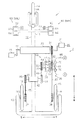
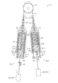
図1に示されるように、三輪自転車1には、各構成部材が取り付けられる本体としてのボディ10と、駆動輪としての右後輪15および左後輪16と、従動輪としての1つの前輪14と、前輪14の舵角を変更する操舵装置2とが設けられている。またこの他に、運転者が右後輪15および左後輪16に動力を入力するための駆動装置20と、駆動装置20から右後輪15および左後輪16に動力を伝達する動力伝達装置30と、駆動装置20の回転を変速する無段変速装置50と、運転者が無段変速装置50の変速比を変更するための操作装置60とが設けられている。なお、操舵装置2は無段変速装置50および操作装置60により構成されている。
As shown in FIG. 1, the three-
ボディ10には、1つの前輪14が取り付けられるメインフレーム11と、右後輪15および左後輪16が取り付けられるサポートフレーム12と、運転者が操作するための各レバーが取付けられるステム13とが設けられている。
The
前輪14は、メインフレーム11に固定された前車軸14Aにより回転可能に支持されている。右後輪15は、サポートフレーム12に固定された右後車軸15Aにより回転可能に支持されている。左後輪16は、サポートフレーム12に固定された左後車軸16Aにより回転可能に支持されている。
The front wheel 14 is rotatably supported by a front axle 14 </ b> A fixed to the
駆動装置20には、運転者が足で漕ぐための右足用および左足用のペダル21と、各ペダル21の回転を動力伝達装置30に伝達する駆動軸22と、駆動軸22を回転可能に支持する第1軸受23とが設けられている。第1軸受23は、メインフレーム11に固定されている。
The
無段変速装置50には、駆動装置20の回転が入力される入力軸52と、入力軸52と一体的に回転する入力ディスク51と、左後輪16に変速後の回転を伝達する出力軸54と、出力軸54と一体的に回転する出力ディスク53とが設けられている。またこの他に、入力ディスク51と出力ディスク53との間に設けられて入力ディスク51から出力ディスク53に回転を伝達する2つのボール55と、入力ディスク51、出力ディスク53および各ボール55を収容するケーシング56とが設けられている。
The continuously
動力伝達装置30には、駆動軸22に固定された駆動スプロケット31と、入力軸52に固定された入力スプロケット32と、出力軸54に固定された出力スプロケット33とが設けられている。また、メインフレーム11をまたいでボディ10の右側から左側に回転を伝達する伝達軸41と、伝達軸41を回転可能に支持する第2軸受42と、伝達軸41の右側の端部に固定された右中間スプロケット34と、伝達軸41の左側の端部に固定された左中間スプロケット35とが設けられている。また、右後車軸15Aに固定された右後輪スプロケット36と、左後車軸16Aに固定された左後輪スプロケット37とが設けられている。
The
動力伝達装置30においては、スプロケット間で動力を伝達するためのチェーンとして次のものが設けられている。すなわち、駆動スプロケット31と入力スプロケット32と右後輪スプロケット36とに巻き掛けられた入力チェーン43と、出力スプロケット33と右中間スプロケット34とに巻き掛けられた右出力チェーン44と、左中間スプロケット35と左後輪スプロケット37とに巻き掛けられた左出力チェーン45とが設けられている。
In the
図2を参照して、無段変速装置50の詳細な構成について説明する。
無段変速装置50においては、入力ディスク51の入力支持面51Aと出力ディスク53の出力支持面53Aとにより各ボール55が支持されている。各ボール55が回転するとき、入力支持面51Aに形成された湾曲面としての入力伝達面51B、および出力支持面53Aに形成された湾曲面としての出力伝達面53Bのそれぞれに対してボール55が摺動する。
A detailed configuration of the continuously
In the continuously
無段変速装置50の内部には、入力ディスク51および出力ディスク53に対する回転軸55Aの傾きを変更するためのねじ機構が設けられている(図示略)。また入力軸52には、図1の操舵レバー63に入力された力によりねじ機構を動作させるためのドラム61が設けられている。ドラム61と操舵レバー63とは、ワイヤ65により互いに接続されている。なお、ドラム61は「変更部材」に相当する。
Inside the continuously
無段変速装置50の変速態様について説明する。
ボール55の回転軸55Aの傾きが変更されたとき、入力伝達面51Bに対してボール55が接触する部分と回転軸55Aとの距離(以下、「第1作用半径R1」)、および出力伝達面53Bに対してボール55が接触する部分と回転軸55Aとの距離(以下、「第2作用半径R2」)が変更される。すなわち、無段変速装置50の変速比が変更される。
A transmission mode of the continuously
When the inclination of the
図2(a)に示されるように、ボール55の回転軸55Aが傾斜しているとき、すなわち入力軸52および出力軸54の軸方向において入力軸52側から出力軸54側に向かうにつれて径方向において外側から内側に向けて回転軸55Aが傾斜しているとき、第2作用半径R2が第1作用半径R1よりも大きくなる。これにより、出力軸54の回転速度が入力軸52の回転速度よりも大きくなるため、すなわち左後輪16の回転速度が右後輪15の回転速度よりも大きくなるため、三輪自転車1が右進する。
As shown in FIG. 2A, when the
図2(b)に示されるように、ボール55の回転軸55Aが傾斜しているとき、すなわち入力軸52および出力軸54の軸方向において入力軸52側から出力軸54側に向かうにつれて径方向において内側から外側に向けて回転軸55Aが傾斜しているとき、第1作用半径R1が第2作用半径R2よりも大きくなる。これにより、出力軸54の回転速度が入力軸52の回転速度よりも小さくなるため、すなわち左後輪16の回転速度が右後輪15の回転速度よりも小さくなるため、三輪自転車1が左進する。
As shown in FIG. 2B, when the
ボール55の回転軸55Aが入力軸52および出力軸54に対して傾斜していないとき、すなわち回転軸55Aが入力軸52および出力軸54の中心線と平行となるとき、第1作用半径R1と第2作用半径R2とが互いに同じ大きさとなる。このため、無段変速装置50の変速比が「1:1」に設定される。
When the
なお以下では、第2作用半径R2が第1作用半径R1よりも大きいときの変速比、および第1作用半径R1が第2作用半径R2よりも大きいときの変速比はそれぞれ「旋回変速比」に相当する。また、第1作用半径R1と第2作用半径R2とが互い同じ大きさのときの変速比は「直進変速比」に相当する。また、変速比が直進変速比のときの無段変速装置50の動作状態を「直進動作状態」とする。また、変速比が旋回変速比のときの無段変速装置50の動作状態を「旋回動作状態」とする。また、無段変速装置50の変速比が旋回変速比から直進変速比に向けて変化するドラム61の動作を「復帰変速動作」とする。また、無段変速装置50の変速比が直進変速比から旋回変速比に向けて変化するドラム61の動作を「旋回変速動作」とする。
In the following, the gear ratio when the second working radius R2 is larger than the first working radius R1 and the gear ratio when the first working radius R1 is larger than the second working radius R2 are respectively referred to as “turning gear ratio”. Equivalent to. Further, the transmission gear ratio when the first working radius R1 and the second working radius R2 are the same size corresponds to the “straight-running gear ratio”. In addition, the operation state of the continuously
図1を参照して、三輪自転車1においての動力の伝達態様について説明する。
三輪自転車1においては、運転者によるペダル21の踏み込み動作により生じる動力が駆動スプロケット31、入力チェーン43、および入力スプロケット32を介して入力軸52に伝達される。また、ペダル21からの動力が入力チェーン43、右後輪スプロケット36、および右後車軸15Aを介して右後輪15に伝達される。
With reference to FIG. 1, the power transmission mode in the three-
In the three-
入力軸52に伝達された動力は、入力ディスク51および出力ディスク53を介して出力軸54に伝達された後、出力スプロケット33、右出力チェーン44、および右中間スプロケット34を介して伝達軸41に伝達される。伝達軸41の動力は、左中間スプロケット35、左出力チェーン45、左後輪スプロケット37および左後車軸16Aを介して左後輪16に伝達される。
The power transmitted to the
このように、ペダル21に入力された動力が各スプロケットおよび各チェーンにより構成される動力伝達経路を介して右後輪15および左後輪16に伝達されることにより、三輪自転車1に推力が発生し、これにともない前輪14が回転して三輪自転車1が前進または後進する。
As described above, the power input to the
三輪自転車1の旋回動作について説明する。
運転者は、三輪自転車1を右進させるとき、右手用の操舵レバー63の操作量を増大させる。このとき、ワイヤ65の移動量に応じてボール55の回転軸55Aが入力軸52および出力軸54に対して傾き、第2作用半径R2が第1作用半径R1よりも大きくなる。これにより、左後輪16の回転速度が右後輪15の回転速度よりも大きくなるため、この回転速度差により三輪自転車1が右進する。
A turning operation of the
When the driver moves the three-
運転者は、三輪自転車1を左進させるとき、左手用の操舵レバー63の操作量を増大させる。このとき、ワイヤ65の移動量に応じてボール55の回転軸55Aが入力軸52および出力軸54に対して傾き、第1作用半径R1が第2作用半径R2よりも大きくなる。これにより、右後輪15の回転速度が左後輪16の回転速度よりも大きくなるため、この回転速度差により三輪自転車1が左進する。
When the driver moves the three-
運転者は、三輪自転車1を右進または左進から直進に戻すとき、操舵レバー63を右進または左進の操作状態から直進の操作状態に戻す。このとき、ワイヤ65が引き戻されてボール55の回転軸55Aが入力軸52および出力軸54に対して平行となり、第1作用半径R1と第2作用半径R2とが同じ大きさとなる。これにより、右後輪15の回転速度と左後輪16の回転速度との差がなくなるため、三輪自転車1が直進する。
When the driver returns the three-
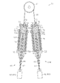
図3を参照して、操作装置60の詳細な構成について説明する。
三輪自転車1には、操作装置60として右手用操作装置60Rおよび左手用操作装置60Lが設けられている。各操作装置60R,60Lには、三輪自転車1の左右方向の中心線を基準として左右対称に構成となる点を除いては共通の構成が採用されているため、以下の説明では共通の符号を用いて各操作装置60R,60Lの構成を説明する。また、「操作装置60」と記載されている部分については、右手用操作装置60Rおよび左手用操作装置60Lの双方を示すものとする。
With reference to FIG. 3, the detailed structure of the operating
The three-
操作装置60には、無段変速装置50の内部に設けられたねじ機構を駆動するドラム61と、運転者が変速比を変更するために操作するハンドル62とが設けられている。またこの他に、ハンドル62の動作をドラム61に伝達するワイヤ65と、ワイヤ65の移動をガイドするワイヤステイ66と、ワイヤ65を保護するワイヤチューブ67と、無段変速装置50の動作状態を旋回動作状態から直進動作状態に復帰させる復帰装置70とが設けられている。
The operating
ハンドル62には、無段変速装置50の変速比の変更により前輪14の舵角を操作するための操舵レバー63と、右後輪15および左後輪16に制動力を付与するための制動レバー64とが上下方向に並べて設けられている。操舵レバー63の操作量が「0」のときには、ワイヤ65が同レバー63にグリップされていない。一方、操舵レバー63の操作量が「0」よりも大きいときには、ワイヤ65が同レバー63にグリップされるため、操舵レバー63の操作量の増加に連動してワイヤ65が移動する。
The
右手用操作装置60Rのワイヤ65と左手用操作装置60Lのワイヤ65とは、互いに接続されている。このため、右手用操作装置60Rおよび左手用操作装置60Lの一方の操舵レバー63が操作されたとき、これに連動して各操作装置60R,60Lの双方においてワイヤ65が移動する。なお、ハンドル62は「操作部材」に相当する。また、ワイヤ65は「接続部材」に相当する。
The
復帰装置70には、内部に空間が形成されたインナハウジング71と、インナハウジング71の外周に取り付けられたアウタハウジング72とが設けられている。またこの他に、ワイヤ65に固定されたクリップ73と、インナハウジング71内において同ハウジング71に対して移動することが可能なシリンダ74と、シリンダ74により圧縮されるスプリング75と、インナハウジング71の開口部においてシリンダ74の移動を制限するストッパ76とが設けられている。スプリング75は、クリップ73の移動方向においてシリンダ74に対してクリップ73とは反対側に設けられている。
The
ドラム61と操舵レバー63との間においては、クリップ73およびシリンダ74およびスプリング75の順にこれらの構成要素が設けられている。シリンダ74およびスプリング75は、インナハウジング71内に設けられている。クリップ73は、操舵レバー63の操作が行われていないときには、インナハウジング71内に設けられている。
Between the
シリンダ74には、潤滑油を保持するための油溜まり74Aが形成されている。この油溜まり74Aは、シリンダ74の外周面においてインナハウジング71の内周面側に開口した2つの環状の溝により形成されている。
The
スプリング75においては、クリップ73側の端部である第1端部75Aがシリンダ74に取り付けられている。また、クリップ73側とは反対側の端部である第2端部75Bがアウタハウジング72に取り付けられている。
In the
なお、インナハウジング71は「第1ハウジング」に相当する。またアウタハウジング72は「第2ハウジング」に相当する。またクリップ73は「連動部材」に相当する。また、シリンダ74は「相対移動部材」に相当する。また、スプリング75は「弾性部材」に相当する。また以下では、クリップ73がシリンダ74に接近する方向を「接近方向」とする。また、クリップ73がシリンダ74から離間する方向を「離間方向」とする。
The
インナハウジング71の外周面には雄ねじ71Aが形成されている。アウタハウジング72の内周面には雌ねじ72Aが形成されている。インナハウジング71およびアウタハウジング72においては、雄ねじ71Aおよび雌ねじ72Aが互いに噛み合わされている。このため、アウタハウジング72をインナハウジング71に対して回転させることにより、軸方向においてのインナハウジング71に対するアウタハウジング72の位置(以下、「ハウジング相対位置」)を変更することができる。すなわち、インナハウジング71およびアウタハウジング72は、接近方向および離間方向において相対的な移動が可能な状態で組み合わせられている。
A
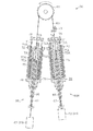
図3および図4を参照して、操作装置60および復帰装置70の動作について説明する。なお図4は、右手用操作装置60Rの操舵レバー63が操作された状態においての操作装置60の断面構造を示している。
With reference to FIG. 3 and FIG. 4, operations of the
図3に示されるように、右手用操作装置60Rおよび左手用操作装置60Lの双方の操舵レバー63が操作されていないとき、スプリング75の長さが自然長となる。このとき、クリップ73がシリンダ74に接触しているが、ワイヤ65によるシリンダ74への押し付けは行われていない。また、ドラム61の回転位置が中立位置に保持されているため、無段変速装置50の変速比が直進変速比に保持される。
As shown in FIG. 3, when the steering levers 63 of both the right
図4に示されるように、左手用操作装置60Lの操舵レバー63が操作されたとき、すなわち操舵レバー63の操作量が「0」の状態から操作量が「0」よりも大きい状態に変更されたとき、同操作装置60Lのワイヤ65が接近方向に移動する。このとき、ワイヤ65の接近方向への移動にともないドラム61が回転する。すなわち、ドラム61が旋回変速動作する。このため、無段変速装置50の変速比が直進変速比から旋回変速比に変更される。
As shown in FIG. 4, when the steering
上記操舵レバー63の操作が行われたとき、ワイヤ65とともにクリップ73が接近方向に移動する。また、クリップ73の接近方向への移動にともないシリンダ74にクリップ73が押し付けられるため、シリンダ74も接近方向に移動する。すなわち、ワイヤ65、クリップ73およびシリンダ74が一体となり接近方向に移動する。また、シリンダ74の移動にともないスプリング75が圧縮されるため、スプリング75の長さが自然長よりも短くなる。
When the steering
また、右手用操作装置60Rにおいては、左手用操作装置60Lによるワイヤ65の移動にともない同操作装置60Rのワイヤ65が離間方向に移動する。このとき、ワイヤ65とともにクリップ73が離間方向に移動する。なお、右手用操作装置60Rにおいてはワイヤ65が操舵レバー63にグリップされていないため、シリンダ74の位置およびスプリング75の長さは変更されない。
In the right-
上記操舵レバー63の操作後において、左手用操作装置60Lの操舵レバー63の操作量が一定となるように同レバー63に継続して力が加えられているとき、同操作装置60Lにおいてはシリンダ74によりスプリング75が縮められた状態が保持される。すなわち、無段変速装置50の動作状態が旋回動作状態に保持される。
After the operation of the steering
その後、左手用操作装置60Lの操舵レバー63に加えられる力が緩められたことにより、スプリング75のばね力がワイヤ65を接近方向に引く力を上回るとき、スプリング75のばね力により同操作装置60Lのシリンダ74が離間方向に移動する。このとき、クリップ73がシリンダ74に接触した状態にあるため、シリンダ74の移動にともないクリップ73も離間方向に移動する。そして、このクリップ73の移動にともなうワイヤ65の移動によりドラム61が中立位置に向けて回転する。すなわち、ドラム61が復帰旋回動作する。このため、無段変速装置50の変速比が旋回変速比から直進変速比に向けて変更される。
Thereafter, when the force applied to the steering
上記ワイヤ65の移動にともないスプリング75が自然長の状態に復帰したとき、左手用操作装置60Lおよび右手用操作装置60Rのそれぞれにおいてクリップ73が初期の位置に復帰する。また、ドラム61の回転位置が中立位置に復帰する。また、無段変速装置50の動作状態が直進動作状態に復帰する。なお、右手用操作装置60Rの操舵レバー63の操作量が「0」の状態、操作量が「0」よりも大きい状態、および操作量が再び「0」となる場合にも上述した説明に準じた態様でワイヤ65、ドラム61および無段変速装置50等が動作する。
When the
以下に、各操作装置60L,60Rの動作のまとめを示す。
左手用操作装置60Lおよび右手用操作装置60Rの操舵レバー63の操作量が「0」のとき、ワイヤ65、クリップ73およびシリンダ74が初期の位置に保持される。また、ドラム61の回転位置が中立位置に保持される。また、無段変速装置50の動作状態が直進動作状態に保持される。
Below, the summary of operation | movement of each operating
When the operation amount of the steering
左手用操作装置60Lの操舵レバー63の操作量が増加するとき、同操作装置60Lのクリップ73およびシリンダ74が接近方向に移動する。また、右手用操作装置60Rにおいて同操作装置60Rのクリップ73が離間方向に移動する。また、同操作装置60Rのシリンダ74は移動しない。また、ドラム61が旋回変速動作する。また、無段変速装置50の変速比が直進変速比との乖離が大きくなる方向に変化する。
When the operation amount of the steering
左手用操作装置60Lの操舵レバー63が「0」よりも大きい操作量で保持されているとき、すなわち無段変速装置50が旋回動作状態にあるとき、左手用操作装置60Lのスプリング75のばね力により同操作装置60Lにおいてドラム61を復帰変速動作させる力がシリンダ74およびクリップ73を介してワイヤ65に付与される。
When the steering
左手用操作装置60Lの操舵レバー63の操作量が減少するとき、同操作装置60Lのクリップ73およびシリンダ74が離間方向に移動する。また、右手用操作装置60Rにおいて同操作装置60Rのクリップ73が接近方向に移動する。また、同操作装置60Rのシリンダ74は移動しない。また、ドラム61が復帰変速動作する。また、無段変速装置50の変速比が直進変速比との乖離が小さくなる方向に変化する。
When the operation amount of the steering
右手用操作装置60Rの操舵レバー63の操作量が増加するとき、同操作装置60Rのクリップ73およびシリンダ74が接近方向に移動する。また、左手用操作装置60Lにおいて同操作装置60Lのクリップ73が離間方向に移動する。また、同操作装置60Lのシリンダ74は移動しない。また、ドラム61が旋回変速動作する。また、無段変速装置50の変速比が直進変速比との乖離が大きくなる方向に変化する。
When the operation amount of the steering
右手用操作装置60Rの操舵レバー63が「0」よりも大きい操作量で保持されているとき、すなわち無段変速装置50が旋回動作状態にあるとき、右手用操作装置60Rのスプリング75のばね力により同操作装置60Rにおいてドラム61を復帰変速動作させる力がシリンダ74およびクリップ73を介してワイヤ65に付与される。
When the steering
右手用操作装置60Rの操舵レバー63の操作量が減少するとき、同操作装置60Rのクリップ73およびシリンダ74が離間方向に移動する。また、左手用操作装置60Lにおいて同操作装置60Lのクリップ73が接近方向に移動する。また、同操作装置60Lのシリンダ74は移動しない。また、ドラム61が復帰変速動作する。また、無段変速装置50の変速比が直進変速比との乖離が小さくなる方向に変化する。
When the operation amount of the steering
図5を参照して、スプリング75の予圧の調整方法について説明する。
復帰装置70においては、ハウジング相対位置を変更することにより、クリップ73がシリンダ74に押し付けられていない状態においてのスプリング75の長さ(以下、「スプリング75の圧縮前長さ」)、すなわちスプリング75の予圧の大きさを変更することができる。
A method for adjusting the preload of the
In the
スプリング75の予圧の大きさが変更されたときには、運転者による操舵レバー63の操作に対する反力の大きさが変更されるため、運転者が操舵レバー63に加える力に対する同レバー63の動作量も変更される。同動作量は、スプリング75の予圧が大きくなるにつれて小さくなる。
When the magnitude of the preload of the
ハウジング相対位置は、インナハウジング71がアウタハウジング72に最大限に収容されている位置を「基準相対位置」とし、インナハウジング71がアウタハウジング72から最大限に突出している位置を「最大突出位置」としたとき、基準相対位置から最大突出位置までの間で変更することができる。
The housing relative position is defined as a “reference relative position” where the
ハウジング相対位置が基準相対位置のとき、スプリング75の圧縮前長さが最も短くなる。一方、ハウジング相対位置が最大突出位置のとき、スプリング75の圧縮前長さが最も長くなる。
When the housing relative position is the reference relative position, the pre-compression length of the
操作装置60においては、上記のとおりハウジング相対位置を変更することができるため、三輪自転車1の運転が行われていないときにハウジング相対位置を変更することにより、操舵レバー63の操作に対する反力の大きさを必要な大きさに調整しておくことが可能となる。
In the operating
(効果)
本実施形態の三輪自転車1によれば以下の効果が得られる。
(1)三輪自転車1の操舵装置2には、右後輪15および左後輪16の回転速度を変更する無段変速装置50と、無段変速装置50の変速比を変更するドラム61とが設けられている。
(effect)
According to the three-
(1) The
この構成によれば、無段変速装置50の変速比の変更ことにより右後輪15の回転速度と左後輪16の回転速度とが互いに異なるものに変更されたときには、前輪14の舵角が変更される。このため、前輪14に連結されたハンドルの操作により同前輪14の舵角を変更する構成が用いられる場合と比較して、操舵のために運転者にかかる負担を小さくすることができる。また、上肢不自由者(例えば、手の力が弱い者、または腕を動かすことができない者)が三輪自転車1に搭乗したときには、上記で仮定した三輪自転車に搭乗したときと比較して、三輪自転車1の運転を容易に行うことができる。
According to this configuration, when the rotational speed of the right
(2)三輪自転車1の操舵装置2には、無段変速装置50の動作状態を旋回動作状態から直進動作状態に復帰させる復帰装置70が設けられている。この構成によれば、操舵レバー63を操作する力が緩められたとき、または操舵レバー63を操作する力が取り除かれたとき、無段変速装置50の変速比が旋回変速比から直進変速比に向けて変化するため、車両直進時の走行安定性が向上する。
(2) The
(3)三輪自転車1の操舵装置2においては、ドラム61を復帰変速動作させる力が復帰装置70からワイヤ65に付与される。この構成によれば、復帰装置70からワイヤ65に付与される力が運転者による操舵レバー63の操作に対する反力として作用する。このため、操舵レバー63の操作に対する反力が生じない場合と比較して、運転者が同レバー63を操作するときの操作性が向上する。
(3) In the
(4)三輪自転車1の操舵装置2においては、右手用操作装置60Rおよび左手用操作装置60Lにおいて独立してスプリング75の圧縮前長さを変更することができる。この構成によれば、例えば、操舵装置2を搭載した車両において右旋回時の速度が左旋回時の速度よりも大きくなる場合、右手用操作装置60Rのスプリング75の予圧を左手用操作装置60Lのスプリング75の予圧よりも大きくすることにより、旋回速度の差を小さくすることができる。
(4) In the
(5)三輪自転車1の操舵装置2においては、右手用操作装置60Rの操舵レバー63および左手用操作装置60Lの操舵レバー63のそれぞれに対応して復帰装置70が設けられている。この構成によれば、例えばドラム61の回転軸に1つのばねを設けてドラム61の回転位置を復帰させる構成とは異なり、右手用操作装置60Rおよび左手用操作装置60Lのいずれの操舵レバー63の操作量が減少するときにもワイヤ65を適切に引き戻すことができる。
(5) In the
(6)三輪自転車1の操舵装置2においては、ハンドル62に操舵レバー63および制動レバー64が設けられている。この構成によれば、右手および左手の一方でブレーキ操作および操舵操作を行うことができる。
(6) In the
(7)三輪自転車1の操舵装置2においては、無段変速装置50の入力軸52と右後輪15とがスプロケットおよびチェーンによりリジットに連結されている。また、出力軸54と左後輪16とがスプロケットおよびチェーンによりリジットに連結されている。
(7) In the
この構成によれば、前進方向または後進方向への動力が入力軸52から右後輪15に直接的に伝達される。また、前進方向または後進方向への動力が出力軸54から左後輪16に直接的に伝達される。このため、入力軸52と右後輪15との間および出力軸54と左後輪16との間の少なくとも一方にワンウェイクラッチが設けられる構成においての課題、すなわちワンウェイクラッチの空回りついて、これが生じることを抑制することができる。これにより、各後輪15,16のうちの回転速度が小さい方にトルクが作用し、各後輪15,16の回転速度差が大きくなるため、操舵性能の低下が抑制される。
According to this configuration, power in the forward direction or the reverse direction is directly transmitted from the
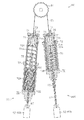
(第2実施形態)
図6を参照して、本発明の第2実施形態について説明する。なお、本実施形態の三輪自転車1は第1実施形態の三輪自転車1に対して次の変更が加えられたものに相当する。すなわち、第1実施形態の復帰装置70においては、ドラム61と操舵レバー63との間にクリップ73、シリンダ74およびスプリング75の順でこれら構成要素が設けられている。これに対して本実施形態の復帰装置80においては、ドラム61と操舵レバー63との間にスプリング75、シリンダ74およびクリップ73の順でこれら構成要素が設けられている。
(Second Embodiment)
A second embodiment of the present invention will be described with reference to FIG. The three-
以下、第1実施形態からの上記変更点を中心に本実施形態の三輪自転車1の構成を説明する。なお、第1実施形態と共通する構成については同一の符号を付して、その説明の一部または全部を適宜省略する。
Hereinafter, the configuration of the three-
復帰装置80には、ハンドル62に固定されたインナハウジング81と、インナハウジング81の外周に取り付けられたアウタハウジング82とが設けられている。またこの他に、ワイヤ65に固定されたクリップ83と、インナハウジング81内において同ハウジング81に対して移動することが可能なピストン84と、ピストン84により圧縮されるスプリング85と、インナハウジング81の開口部においてピストン84の移動を制限するストッパ86とが設けられている。スプリング85は、クリップ83の移動方向においてピストン84に対してクリップ83とは反対側に設けられている。
The
ドラム61と操舵レバー63との間においては、スプリング85、ピストン84およびクリップ83の順にこれらの構成要素が設けられている。ピストン84およびスプリング85は、インナハウジング81内に設けられている。クリップ83は、操舵レバー63の操作が行われていないときには、インナハウジング81内に設けられている。
Between the
ピストン84には、スプリング85においてのクリップ83側の端部である第1端部85Aが取り付けられている。またアウタハウジング82には、スプリング85においてのクリップ83側とは反対側の端部である第2端部85Bが取り付けられている。
A
インナハウジング81には、第1実施形態の油溜まり74Aと同様の態様で油溜まり81Bが形成されている。また、インナハウジング81およびアウタハウジング82においては、第1実施形態と同様の態様で雄ねじ81Aおよび雌ねじ82Aが互いに噛み合わされている。アウタハウジング82は、操舵レバー63に固定されている。
In the
各操作装置60R,60Lの動作について説明する。
左手用操作装置60Lおよび右手用操作装置60Rの操舵レバー63の操作量が「0」のとき、ワイヤ65、クリップ83およびピストン84が初期の位置に保持される。また、ドラム61の回転位置が中立位置に保持される。また、無段変速装置50の動作状態が直進動作状態に保持される。
The operation of each
When the operation amount of the steering
左手用操作装置60Lの操舵レバー63の操作量が増加するとき、同操作装置60Lのクリップ73が離間方向に移動する。また、同操作装置60Lのシリンダ74は移動しない。また、右手用操作装置60Rにおいて同操作装置60Rのクリップ73およびシリンダ74が接近方向に移動する。また、ドラム61が旋回変速動作する。また、無段変速装置50の変速比が直進変速比との乖離が大きくなる方向に変化する。
When the operation amount of the steering
左手用操作装置60Lの操舵レバー63が「0」よりも大きい操作量で保持されているとき、すなわち無段変速装置50が旋回動作状態にあるとき、右手用操作装置60Rのスプリング85のばね力により同操作装置60Rにおいてドラム61を復帰変速動作させる力がピストン84およびクリップ83を介してワイヤ65に付与される。
When the steering
左手用操作装置60Lの操舵レバー63の操作量が減少するとき、同操作装置60Lのクリップ73が接近方向に移動する。また、同操作装置60Lのシリンダ74は移動しない。また、右手用操作装置60Rにおいて同操作装置60Rのクリップ73およびシリンダ74が離間方向に移動する。また、ドラム61が復帰変速動作する。また、無段変速装置50の変速比が直進変速比との乖離が小さくなる方向に変化する。
When the operation amount of the steering
右手用操作装置60Rの操舵レバー63の操作量が増加するとき、同操作装置60Rのクリップ73が離間方向に移動する。また、同操作装置60Rのシリンダ74は移動しない。また、左手用操作装置60Lにおいて同操作装置60Lのクリップ73およびシリンダ74が接近方向に移動する。また、ドラム61が旋回変速動作する。また、無段変速装置50の変速比が直進変速比との乖離が大きくなる方向に変化する。
When the operation amount of the steering
右手用操作装置60Rの操舵レバー63が「0」よりも大きい操作量で保持されているとき、すなわち無段変速装置50が旋回動作状態にあるとき、左手用操作装置60Lのスプリング85のばね力により同操作装置60Lにおいてドラム61を復帰変速動作させる力がピストン84およびクリップ83を介してワイヤ65に付与される。
When the steering
右手用操作装置60Rの操舵レバー63の操作量が減少するとき、同操作装置60Rのクリップ73が接近方向に移動する。また、同操作装置60Rのシリンダ74は移動しない。また、左手用操作装置60Lにおいて同操作装置60Lのクリップ73およびシリンダ74が離間方向に移動する。また、ドラム61が復帰変速動作する。また、無段変速装置50の変速比が直進変速比との乖離が小さくなる方向に変化する。
When the operation amount of the steering
(効果)
本実施形態の三輪自転車1によれば、第1実施形態の(1)〜(7)の効果に準じた効果が得られる。
(effect)
According to the three-
(その他の実施形態)
なお、本発明の実施態様は上記各実施形態に限られるものではなく、例えば以下に示すように変更することもできる。また以下の各変形例は、上記各実施形態についてのみ適用されるものではなく、異なる変形例同士を互いに組み合わせて実施することもできる。
(Other embodiments)
Note that the embodiments of the present invention are not limited to the above-described embodiments, and can be modified as shown below, for example. The following modifications are not applied only to the above embodiments, and different modifications can be combined with each other.
・上記各実施形態では、動力伝達装置30としてスプロケットおよびチェーンにより動力を伝達するものを用いているが、スプロケットおよびチェーンに代えてプーリおよびベルトを用いることもできる。
In each of the above embodiments, the
・上記各実施形態では、右後輪15の回転速度と左後輪16の回転速度とを無段変速装置50により互いに異ならせることにより前輪14の舵角を変更する構成を採用しているが、同舵角を変更するための構成は同実施形態に例示した内容に限られるものではない。例えば、右前輪および左前輪を備えるとともに、右前輪の回転速度と左前輪の回転速度とを無段変速装置により互いに異ならせることにより、右前輪および左前輪の舵角を変更することもできる。この場合、上記実施形態と同様に後輪として右後輪15および左後輪16を備える構成、および後輪を1つだけ備える構成の双方を採用することができる。
In each of the above embodiments, a configuration is adopted in which the steering angle of the front wheel 14 is changed by making the rotational speed of the right
・上記各実施形態では、無段変速装置50として2つのボール55を有するものを用いているが、1つまたは3つ以上のボール55を有する無段変速装置を用いることもできる。また、2つのボール55に代えて、ディスクを有する無段変速装置を用いることもできる。
In each of the above-described embodiments, the continuously
・上記各実施形態では、無段変速装置50としてハンドル62の操舵レバー63の操作により変速比が変更されるものを用いているが、変速比を変更するための構成を例えば次のように変更することもできる。すなわち、運転者の腰の角度に連動して無段変速装置50の変速比を変更することもできる。また、ペダル21の踏み込み量に連動して無段変速装置50の変速比を変更することもできる。
In each of the above embodiments, the continuously
・上記各実施形態では、運転者のペダル21の操作にともない入力される動力により駆動輪としての右後輪15および左後輪16を回転させているが、すなわち運転者のペダル21の操作により動力を得ているが、これに代えて、電動モータまたは内燃機関等により動力を得る車両として三輪自動車を構成することもできる。
In each of the above embodiments, the right
・上記各実施形態では、変速装置として無段変速装置50を用いているが、右後輪15の回転速度と左後輪16の回転速度とを互いに異なるものにすることが可能な変速装置であれば、無段変速装置50とは別の変速装置を用いることもできる。
In each of the above embodiments, the continuously
・上記各実施形態では、三輪自転車1に本発明を適用した構成を例示しているが、四輪自転車、四輪自動車および左右二輪の原動機に本発明を適用することもできる。この場合にも、上記各実施形態に準じた態様で本発明を実施することにより同実施形態の効果に準じた効果が得られる。
In each of the above embodiments, the configuration in which the present invention is applied to the three-
1…三輪自転車、2…操舵装置、10…ボディ、11…メインフレーム、12…サポートフレーム、13…ステム、14…前輪、14A…前車軸、15…右後輪、15A…右後車軸、16…左後輪、16A…左後車軸、20…駆動装置、21…ペダル、22…駆動軸、23…第1軸受、30…動力伝達装置、31…駆動スプロケット、32…入力スプロケット、33…出力スプロケット、34…右中間スプロケット、35…左中間スプロケット、36…右後輪スプロケット、37…左後輪スプロケット、41…伝達軸、42…第2軸受、43…入力チェーン、44…右出力チェーン、45…左出力チェーン、50…無段変速装置、51…入力ディスク、51A…入力支持面、51B…入力伝達面、52…入力軸、53…出力ディスク、53A…出力支持面、53B…出力伝達面、54…出力軸、55…ボール、55A…回転軸、56…ケーシング、60…操作装置、60R…右手用操作装置、60L…左手用操作装置、61…ドラム(変更部材)、62…ハンドル(操作部材)、63…操舵レバー(操舵レバー)、64…制動レバー(制動レバー)、65…ワイヤ(接続部材)、66…ワイヤステイ、67…ワイヤチューブ、70…復帰装置(復帰装置)、71…インナハウジング(第1ハウジング)、71A…雄ねじ、72…アウタハウジング(第2ハウジング)、72A…雌ねじ、73…クリップ(連動部材)、74…シリンダ(相対移動部材)、74A…油溜まり、75…スプリング(弾性部材)、75A…第1端部(第1端部)、75B…第2端部(第2端部)、76…ストッパ、80…復帰装置(復帰装置)、81…インナハウジング(第1ハウジング)、81A…雄ねじ、82…アウタハウジング(第2ハウジング)、82A…雌ねじ、83…クリップ(連動部材)、84…ピストン(相対移動部材)、85…スプリング(弾性部材)、85A…第1端部(第1端部)、85B…第2端部(第2端部)。
DESCRIPTION OF
Claims (7)
この変速装置内の機構を動作させて前記変速比を変更する変更部材が設けられていること、
ならびに、車両が直進するときの前記変速比を直進変速比とし、車両が旋回するときの前記変速比を旋回変速比とし、前記変速比が前記直進変速比のときの前記変速装置の動作状態を直進動作状態とし、前記変速比が前記旋回変速比のときの前記変速装置の動作状態を旋回動作状態として、前記変速装置の動作状態を前記旋回動作状態から前記直進動作状態に復帰させる復帰装置が設けられていること
を特徴とする車両の操舵装置。 A transmission device is provided for changing the rotational speed of the right drive wheel and the rotational speed of the left drive wheel to a magnitude corresponding to the gear ratio;
A changing member is provided for operating the mechanism in the transmission to change the gear ratio;
In addition, the transmission ratio when the vehicle goes straight is defined as a straight transmission ratio, the transmission ratio when the vehicle turns is defined as a turning transmission ratio, and the operating state of the transmission when the transmission ratio is the straight transmission ratio. A return device that sets the operation state of the transmission when the transmission gear ratio is the turning gear ratio to the turning operation state, and returns the operation state of the transmission device from the turning operation state to the straight operation state; A vehicle steering apparatus characterized by being provided.
当該操舵装置には、前記変更部材を駆動する操作装置が設けられていること、
この操作装置には、運転者により操作される操作部材と、この操作部材に入力された力により前記変更部材を駆動する接続部材とが設けられていること、
ならびに、前記変速比が前記旋回変速比から前記直進変速比に向けて変化する前記変更部材の動作を復帰変速動作として、前記変更部材を同復帰変速動作させる力が前記復帰装置から前記接続部材に付与されること
を特徴とする車両の操舵装置。 The vehicle steering apparatus according to claim 1,
The steering device is provided with an operating device for driving the change member;
The operation device is provided with an operation member operated by a driver and a connection member that drives the change member by a force input to the operation member.
In addition, the operation of the changing member, in which the speed ratio changes from the turning speed ratio toward the straight speed ratio, is referred to as a return speed change operation, and the force that causes the change member to perform the return speed change operation from the return device to the connection member A vehicle steering apparatus characterized by being given.
前記復帰装置には、前記接続部材に対して移動する相対移動部材と、前記接続部材に連動する連動部材と、この連動部材の移動方向において前記相対移動部材に対して前記連動部材とは反対側に設けられた弾性部材とが設けられていること、
前記変更部材と前記操作部材との間においては前記連動部材および前記相対移動部材および前記弾性部材の順にこれらの構成要素が設けられていること、
前記変速比が前記直進変速比から前記旋回変速比に向けて変化する前記変更部材の動作を旋回変速動作とし、前記連動部材が前記相対移動部材に接近する方向を接近方向とし、前記連動部材が前記相対移動部材から離間する方向を離間方向として、前記操作部材の操作により前記接続部材が前記接近方向に移動するとき、前記変更部材が前記旋回変速動作すること、
ならびに、前記操作部材の操作により前記変速装置が前記旋回動作状態にあるとき、前記弾性部材の復元力により前記変更部材を前記復帰変速動作させる力が前記相対移動部材および前記連動部材を介して前記接続部材に付与されること
を特徴とする車両の操舵装置。 The vehicle steering apparatus according to claim 2,
The return device includes a relative moving member that moves relative to the connecting member, an interlocking member that interlocks with the connecting member, and a side opposite to the interlocking member with respect to the relative moving member in a moving direction of the interlocking member. An elastic member provided in
These components are provided in the order of the interlocking member, the relative movement member and the elastic member between the change member and the operation member,
The operation of the changing member in which the speed ratio changes from the straight speed ratio toward the turning speed ratio is a turning speed change operation, the direction in which the interlocking member approaches the relative movement member is an approaching direction, and the interlocking member is When the connecting member moves in the approaching direction by the operation of the operating member, with the direction away from the relative moving member as the separating direction, the changing member performs the turning speed change operation,
In addition, when the transmission device is in the turning operation state by the operation of the operation member, a force that causes the change member to perform the return shift operation by the restoring force of the elastic member is transmitted through the relative movement member and the interlocking member. A steering apparatus for a vehicle, characterized in that the steering apparatus is attached to a connection member.
前記操作装置として、右手用操作装置および左手用操作装置が設けられていること、
前記右手用操作装置の操作部材の操作により同操作装置の前記連動部材が前記接近方向に移動するとき、前記左手用操作装置において同操作装置の前記連動部材が前記離間方向に移動するとともに前記変更部材が前記旋回変速動作すること、
前記左手用操作装置の操作部材の操作により同操作装置の前記連動部材が前記接近方向に移動するとき、前記右手用操作装置において同操作装置の前記連動部材が前記離間方向に移動するとともに前記変更部材が前記旋回変速動作すること、
前記右手用操作装置の操作部材の操作により前記変速装置が前記旋回動作状態にあるとき、前記右手用操作装置の弾性部材の復元力により同操作装置において前記変更部材を前記復帰変速動作させる力が同操作装置の前記相対移動部材および前記連動部材を介して前記接続部材に付与されること、
ならびに、前記左手用操作装置の操作部材の操作により前記変速装置が前記旋回動作状態にあるとき、前記左手用操作装置の弾性部材の復元力により同操作装置において前記変更部材を前記復帰変速動作させる力が同操作装置の前記相対移動部材および前記連動部材を介して前記接続部材に付与されること
を特徴とする車両の操舵装置。 The vehicle steering apparatus according to claim 3, wherein
As the operation device, a right-hand operation device and a left-hand operation device are provided,
When the interlocking member of the operating device moves in the approaching direction by the operation of the operating member of the righthand operating device, the interlocking member of the operating device moves in the separating direction and the change in the left-hand operating device. The member performs the swivel shift operation;
When the interlocking member of the operating device moves in the approaching direction by the operation of the operating member of the left hand operating device, the interlocking member of the operating device moves in the separating direction and the change in the operating device for the right hand The member performs the swivel shift operation;
When the transmission device is in the turning operation state by operating the operation member of the right-hand operation device, the restoring force of the elastic member of the right-hand operation device causes a force to cause the change member to perform the return shift operation in the operation device. Being provided to the connection member via the relative movement member and the interlocking member of the operating device;
In addition, when the transmission is in the turning operation state by operating the operation member of the left-hand operation device, the return member performs the return shift operation in the operation device by the restoring force of the elastic member of the left-hand operation device. A vehicle steering apparatus, wherein force is applied to the connection member via the relative movement member and the interlocking member of the operation device.
前記操作装置として、右手用操作装置および左手用操作装置が設けられていること、
前記復帰装置には、前記接続部材に対して移動する相対移動部材と、前記接続部材に連動する連動部材と、この連動部材の移動方向において前記相対移動部材に対して前記連動部材とは反対側に設けられた弾性部材とが設けられていること、
前記変更部材と前記操作部材との間においては前記弾性部材および前記相対移動部材および前記連動部材の順にこれらの構成要素が設けられていること、
前記変速比が前記直進変速比から前記旋回変速比に向けて変化する前記変更部材の動作を旋回変速動作とし、前記連動部材が前記相対移動部材に接近する方向を接近方向とし、前記連動部材が前記相対移動部材から離間する方向を離間方向として、
前記右手用操作装置の操作部材の操作により同操作装置の前記連動部材が前記離間方向に移動するとき、前記左手用操作装置において同操作装置の前記連動部材が前記接近方向に移動するとともに前記変更部材が前記旋回変速動作すること、
前記左手用操作装置の操作部材の操作により同操作装置の前記連動部材が前記離間方向に移動するとき、前記右手用操作装置において同操作装置の前記連動部材が前記接近方向に移動するとともに前記変更部材が前記旋回変速動作すること、
前記右手用操作装置の操作部材の操作により前記変速装置が前記旋回動作状態にあるとき、前記左手用操作装置の弾性部材の復元力により同操作装置において前記変更部材を前記復帰変速動作させる力が同操作装置の前記相対移動部材および前記連動部材を介して前記接続部材に付与されること、
ならびに、前記左手用操作装置の操作部材の操作により前記変速装置が前記旋回動作状態にあるとき、前記右手用操作装置の弾性部材の復元力により同操作装置において前記変更部材を前記復帰変速動作させる力が同操作装置の前記相対移動部材および前記連動部材を介して前記接続部材に付与されること
を特徴とする車両の操舵装置。 The vehicle steering apparatus according to claim 2,
As the operation device, a right-hand operation device and a left-hand operation device are provided,
The return device includes a relative moving member that moves relative to the connecting member, an interlocking member that interlocks with the connecting member, and a side opposite to the interlocking member with respect to the relative moving member in a moving direction of the interlocking member. An elastic member provided in
These components are provided in the order of the elastic member and the relative movement member and the interlocking member between the change member and the operation member,
The operation of the changing member in which the speed ratio changes from the straight speed ratio toward the turning speed ratio is a turning speed change operation, the direction in which the interlocking member approaches the relative movement member is an approaching direction, and the interlocking member is A direction away from the relative movement member is a separation direction,
When the interlocking member of the operating device moves in the separation direction by operation of the operating member of the right-hand operating device, the interlocking member of the operating device moves in the approaching direction and the change in the left-hand operating device. The member performs the swivel shift operation;
When the interlocking member of the operating device moves in the separation direction by the operation of the operating member of the left-hand operating device, the interlocking member of the operating device moves in the approaching direction and the change in the right-hand operating device. The member performs the swivel shift operation;
When the transmission device is in the turning operation state by operating the operation member of the right-hand operation device, the restoring force of the elastic member of the left-hand operation device causes a force to cause the change member to perform the return shift operation in the operation device. Being provided to the connection member via the relative movement member and the interlocking member of the operating device;
In addition, when the transmission is in the turning operation state by operating the operation member of the left-hand operation device, the return member performs the return shift operation in the operation device by the restoring force of the elastic member of the right-hand operation device. A vehicle steering apparatus, wherein force is applied to the connection member via the relative movement member and the interlocking member of the operation device.
前記弾性部材においての前記連動部材側の端部である第1端部が前記相対移動部材に取り付けられていること、
前記復帰装置には、前記接近方向および前記離間方向において相対的な移動が可能な第1ハウジングおよび第2ハウジングが設けられていること、
ならびに、前記弾性部材においての前記連動部材側とは反対側の端部である第2端部が前記第2ハウジングに取り付けられていること
を特徴とする車両の操舵装置。 In the vehicle steering apparatus according to claim 4 or 5,
A first end which is an end of the elastic member on the interlocking member side is attached to the relative movement member;
The return device is provided with a first housing and a second housing capable of relative movement in the approaching direction and the separating direction;
And a second end portion of the elastic member opposite to the interlocking member side is attached to the second housing.
前記操作部材には、前記接続部材に連結された操舵レバーと、前記右駆動輪および前記左駆動輪を制動するための制動レバーとが設けられていること
を特徴とする車両の操舵装置。 The vehicle steering apparatus according to any one of claims 2 to 6,
A steering apparatus for a vehicle, wherein the operation member is provided with a steering lever coupled to the connection member, and a braking lever for braking the right driving wheel and the left driving wheel.
Priority Applications (1)
| Application Number | Priority Date | Filing Date | Title |
|---|---|---|---|
| JP2011005350A JP5707952B2 (en) | 2011-01-13 | 2011-01-13 | Vehicle steering device |
Applications Claiming Priority (1)
| Application Number | Priority Date | Filing Date | Title |
|---|---|---|---|
| JP2011005350A JP5707952B2 (en) | 2011-01-13 | 2011-01-13 | Vehicle steering device |
Publications (2)
| Publication Number | Publication Date |
|---|---|
| JP2012144198A true JP2012144198A (en) | 2012-08-02 |
| JP5707952B2 JP5707952B2 (en) | 2015-04-30 |
Family
ID=46788233
Family Applications (1)
| Application Number | Title | Priority Date | Filing Date |
|---|---|---|---|
| JP2011005350A Expired - Fee Related JP5707952B2 (en) | 2011-01-13 | 2011-01-13 | Vehicle steering device |
Country Status (1)
| Country | Link |
|---|---|
| JP (1) | JP5707952B2 (en) |
Citations (2)
| Publication number | Priority date | Publication date | Assignee | Title |
|---|---|---|---|---|
| JP2002037119A (en) * | 2000-07-21 | 2002-02-06 | Yanmar Agricult Equip Co Ltd | Work vehicle |
| JP2002250421A (en) * | 2000-12-21 | 2002-09-06 | Kayseven Co Ltd | Variable speed change gear |
-
2011
- 2011-01-13 JP JP2011005350A patent/JP5707952B2/en not_active Expired - Fee Related
Patent Citations (2)
| Publication number | Priority date | Publication date | Assignee | Title |
|---|---|---|---|---|
| JP2002037119A (en) * | 2000-07-21 | 2002-02-06 | Yanmar Agricult Equip Co Ltd | Work vehicle |
| JP2002250421A (en) * | 2000-12-21 | 2002-09-06 | Kayseven Co Ltd | Variable speed change gear |
Also Published As
| Publication number | Publication date |
|---|---|
| JP5707952B2 (en) | 2015-04-30 |
Similar Documents
| Publication | Publication Date | Title |
|---|---|---|
| JP5523636B1 (en) | Electric assist bicycle | |
| US9994284B2 (en) | Bicycle assist unit | |
| JP6226115B2 (en) | Electric assist bicycle | |
| GB2481230A (en) | Arm powered cycle | |
| CN106604863A (en) | electric assist bicycle | |
| JP2016165911A (en) | Electric bicycle | |
| CN106414227A (en) | Electrically assisted bicycle | |
| JP6820244B2 (en) | Bicycle transmission and bicycle assist system equipped with it | |
| JP2002525537A (en) | Transmission and steering gear for vehicles | |
| JP6214778B2 (en) | Motorcycle reverse gear | |
| JP6118569B2 (en) | Variable field motor and electric vehicle | |
| JP5707952B2 (en) | Vehicle steering device | |
| WO2012021023A2 (en) | Bicycle for driving front wheel by operating handle unit to reciprocate in back and forth movement | |
| CN109154335A (en) | Power transmission | |
| EP2055623B1 (en) | Dual-mode wheel rotating apparatus | |
| CN113167378B (en) | Transmission unit for a motor vehicle with a reverse drive and motor vehicle comprising said transmission unit | |
| KR20030067016A (en) | Device for driving forward bicycle | |
| JP6168783B2 (en) | bicycle | |
| JP2815854B2 (en) | Vehicle forward / reverse switching limiter | |
| JP2014008933A (en) | Vehicle steering device | |
| TWI885055B (en) | Crank assembly for human-powered vehicles | |
| KR101644747B1 (en) | Cycle with single wheel | |
| TW202134110A (en) | Bicycle energy storage power assisting system | |
| JPH04197103A (en) | Sulky working machine | |
| JP5896736B2 (en) | Shift operating device |
Legal Events
| Date | Code | Title | Description |
|---|---|---|---|
| A621 | Written request for application examination |
Free format text: JAPANESE INTERMEDIATE CODE: A621 Effective date: 20131223 |
|
| A977 | Report on retrieval |
Free format text: JAPANESE INTERMEDIATE CODE: A971007 Effective date: 20140626 |
|
| A131 | Notification of reasons for refusal |
Free format text: JAPANESE INTERMEDIATE CODE: A131 Effective date: 20140701 |
|
| A521 | Written amendment |
Free format text: JAPANESE INTERMEDIATE CODE: A523 Effective date: 20140829 |
|
| TRDD | Decision of grant or rejection written | ||
| A01 | Written decision to grant a patent or to grant a registration (utility model) |
Free format text: JAPANESE INTERMEDIATE CODE: A01 Effective date: 20150203 |
|
| A61 | First payment of annual fees (during grant procedure) |
Free format text: JAPANESE INTERMEDIATE CODE: A61 Effective date: 20150216 |
|
| R150 | Certificate of patent or registration of utility model |
Ref document number: 5707952 Country of ref document: JP Free format text: JAPANESE INTERMEDIATE CODE: R150 |
|
| LAPS | Cancellation because of no payment of annual fees |