JP2012144186A - Propulsion casing of outboard motor - Google Patents

Propulsion casing of outboard motor Download PDF

Info

Publication number
JP2012144186A
JP2012144186A JP2011005102A JP2011005102A JP2012144186A JP 2012144186 A JP2012144186 A JP 2012144186A JP 2011005102 A JP2011005102 A JP 2011005102A JP 2011005102 A JP2011005102 A JP 2011005102A JP 2012144186 A JP2012144186 A JP 2012144186A
Authority
JP
Japan
Prior art keywords
shift rod
casing
shift
outboard motor
housing
Prior art date
Legal status (The legal status is an assumption and is not a legal conclusion. Google has not performed a legal analysis and makes no representation as to the accuracy of the status listed.)
Granted
Application number
JP2011005102A
Other languages
Japanese (ja)
Other versions
JP5630277B2 (en
Inventor
Shuichi Sugiyama
修一 杉山
Current Assignee (The listed assignees may be inaccurate. Google has not performed a legal analysis and makes no representation or warranty as to the accuracy of the list.)
Suzuki Motor Corp
Original Assignee
Suzuki Motor Corp
Priority date (The priority date is an assumption and is not a legal conclusion. Google has not performed a legal analysis and makes no representation as to the accuracy of the date listed.)
Filing date
Publication date
Application filed by Suzuki Motor Corp filed Critical Suzuki Motor Corp
Priority to JP2011005102A priority Critical patent/JP5630277B2/en
Publication of JP2012144186A publication Critical patent/JP2012144186A/en
Application granted granted Critical
Publication of JP5630277B2 publication Critical patent/JP5630277B2/en
Active legal-status Critical Current
Anticipated expiration legal-status Critical

Links

Images

Landscapes

  • Gear-Shifting Mechanisms (AREA)

Abstract

【課題】船外機の仕様変更等に有効に対応可能で、コスト低減に効果的に寄与する船外機の推進ケーシングを提供する。
【解決手段】下部ケーシング26内にドライブシャフト22及びプロペラシャフト36を切換可能に接続するギア装置と、ギア装置の前方に配置され、その接続状態を切り換えるシフト装置59,60と、シフト装置を操作するためのシフトロッド23とを備える。シフトロッド23を保持するシフトロッドハウジング35の上面に、上部ケーシング12a及び下部ケーシング26の接合面の一部が設定される。
【選択図】図3
A propulsion casing for an outboard motor capable of effectively responding to a change in specifications of the outboard motor and effectively contributing to cost reduction is provided.
A gear device that connects a drive shaft 22 and a propeller shaft 36 in a lower casing 26 in a switchable manner, shift devices 59 and 60 that are arranged in front of the gear device and switch the connection state, and operate the shift device. And a shift rod 23. A part of the joint surface of the upper casing 12 a and the lower casing 26 is set on the upper surface of the shift rod housing 35 that holds the shift rod 23.
[Selection] Figure 3

Description

本発明は、ドライブシャフトと推進プロペラがギア装置を介して連結される船外機、特にその推進ケーシング構造に関する。   The present invention relates to an outboard motor in which a drive shaft and a propeller are connected via a gear device, and more particularly to a propulsion casing structure thereof.

この種の船外機において一般に、船体の後部に支持されてその下部が水中に没入可能としたロアユニットを備えている。例えば特許文献1に開示される船外機においてその前後進切換装置の構造は、第1のシフトロッド(31)と第2のシフトロッド(32)とが、推進ケーシング(16)の上部ケーシング(16A)と下部ケーシング(16B)との分割部に配置された支持基板(34)を介して下部ケーシング(16B)に回動自在に支持され、支持基板(34)は全体を推進ケーシング(16)に収容している。   In general, this type of outboard motor is provided with a lower unit that is supported at the rear of the hull and whose lower part can be immersed in water. For example, in the outboard motor disclosed in Patent Document 1, the structure of the forward / reverse switching device is such that the first shift rod (31) and the second shift rod (32) are the upper casing of the propulsion casing (16) ( 16A) and a lower casing (16B) are rotatably supported by the lower casing (16B) via a supporting substrate (34) arranged in a divided portion, and the supporting substrate (34) is entirely propulsion casing (16). Is housed in.

特許第2683691号公報Japanese Patent No. 2668391

しかしながら、特許文献1に開示されるような船外機においては、第1のシフトロッド(31)と第2のシフトロッド(32)のオフセット量が大きくなると、それに応じて上部ケーシング(16A)の下部ケーシング(16B)との接合部を拡大する必要がある。下部ケーシング(16B)を変更する際には上部ケーシング(16A)も設計変更しなければならず、製造コストが嵩む等の問題があった。   However, in an outboard motor as disclosed in Patent Document 1, when the offset amount of the first shift rod (31) and the second shift rod (32) increases, the upper casing (16A) It is necessary to enlarge the joint with the lower casing (16B). When the lower casing (16B) is changed, the design of the upper casing (16A) must also be changed, which causes problems such as increased manufacturing costs.

本発明はかかる実情に鑑み、船外機の仕様変更等に有効に対応可能で、コスト低減に効果的に寄与する船外機の推進ケーシングを提供することを目的とする。   In view of such circumstances, an object of the present invention is to provide a propulsion casing for an outboard motor that can effectively cope with a change in specifications of the outboard motor and contributes effectively to cost reduction.

本発明の船外機の推進ケーシングは、船体の後部に支持されて、エンジン駆動力を伝達するドライブシャフトが垂設される上部ケーシング及び下部ケーシングを含む推進ケーシングを有する船外機において、前記下部ケーシング内に前記ドライブシャフト及びプロペラシャフトを切換可能に接続するギア装置と、該ギア装置の前方に配置され、その接続状態を切り換えるシフト装置と、このシフト装置を操作するためのシフトロッドとを備え、前記シフトロッドを保持するシフトロッドハウジングの上面に、前記上部ケーシング及び前記下部ケーシングの接合面の一部が設定されることを特徴とする。   The propulsion casing of the outboard motor according to the present invention is an outboard motor having a propulsion casing that is supported by a rear portion of a hull and includes a top casing and a bottom casing on which a drive shaft that transmits engine driving force is suspended. A gear device that connects the drive shaft and the propeller shaft in a casing in a switchable manner, a shift device that is disposed in front of the gear device and switches the connection state, and a shift rod for operating the shift device. A part of the joint surface of the upper casing and the lower casing is set on the upper surface of the shift rod housing that holds the shift rod.

また、本発明の船外機の推進ケーシングにおいて、前記シフトロッドは、前記上部ケーシングの前外側に沿って配置された上部シフトロッドとこの上部シフトロッドの前方にオフセットして前記下部ケーシング内に配置された下部シフトロッドとに分割構成され、前記上部シフトロッド及び前記下部シフトロッドの連結部に前記シフトロッドハウジングが配置されることを特徴とする。   Further, in the propulsion casing of the outboard motor according to the present invention, the shift rod is disposed in the lower casing offset to the front of the upper shift rod and the upper shift rod disposed along the front outer side of the upper casing. The shift rod housing is divided into a plurality of lower shift rods, and the shift rod housing is disposed at a connecting portion of the upper shift rod and the lower shift rod.

また、本発明の船外機の推進ケーシングにおいて、前記シフトロッドハウジングは、前記下部シフトロッドの収容部の上部開口を覆うように前記下部ケーシングの上面に固定されると共に、その上面に、前記接合面の先端部が形成されることを特徴とする。   Further, in the propulsion casing of the outboard motor of the present invention, the shift rod housing is fixed to the upper surface of the lower casing so as to cover the upper opening of the housing portion of the lower shift rod, and the joint is attached to the upper surface thereof. A front end portion of the surface is formed.

また、本発明の船外機の推進ケーシングにおいて、前記シフトロッドハウジングの上面に形成される接合面の前部が前方へ延出し、この延出部が外観を構成することを特徴とする。   In the propulsion casing of the outboard motor according to the present invention, a front portion of a joint surface formed on the upper surface of the shift rod housing extends forward, and the extended portion constitutes an appearance.

また、本発明の船外機の推進ケーシングにおいて、前記下部シフトロッドの収容部の後方に冷却水路が隣接配置され、前記シフトロッドハウジングの内側端縁が前記冷却水路に臨むように形成されることを特徴とする。   Further, in the propulsion casing of the outboard motor according to the present invention, a cooling water channel is disposed adjacent to the rear of the housing portion of the lower shift rod, and an inner edge of the shift rod housing is formed to face the cooling water channel. It is characterized by.

本発明によれば、例えば仕様変更等の際ギアケース内のギア装置を大型化する場合等にいおいても、ミッドユニット及びロアユニットの接合面自体は何ら変更が生じることないため、ミッドユニット側の設計変更を伴うことなく船外機の仕様変更に対応することができる。また、シフトロッドハウジングの延出部が外部に露呈して外観を構成することで、外観形状における設計自由度が拡大し、より意匠性を向上することができる。   According to the present invention, even when the gear device in the gear case is enlarged, for example, when the specification is changed, the joining surface itself of the mid unit and the lower unit is not changed at all. It is possible to respond to changes in outboard motor specifications without any design changes on the side. In addition, since the extended portion of the shift rod housing is exposed to the outside to configure the appearance, the degree of design freedom in the appearance shape can be expanded, and the design can be further improved.

本発明に係る船外機の全体概略構成例を示す左側面図である。1 is a left side view showing an overall schematic configuration example of an outboard motor according to the present invention. 本発明に係る船外機のエンジンユニットまわりの前方斜視図である。FIG. 3 is a front perspective view around the engine unit of the outboard motor according to the present invention. 本発明に係る船外機ロアユニットの内部構成例を示す断面図である。It is sectional drawing which shows the internal structural example of the outboard motor lower unit which concerns on this invention. 本発明に係る船外機ロアユニットの分解斜視図である。It is a disassembled perspective view of the outboard motor lower unit which concerns on this invention. 本発明に係る船外機ロアユニットのギアケースの主要構成を示す分解斜視図である。It is a disassembled perspective view which shows the main structures of the gear case of the outboard motor lower unit which concerns on this invention. 本発明に係る船外機ロアユニットのギアケースの主要構成を示す分解斜視図である。It is a disassembled perspective view which shows the main structures of the gear case of the outboard motor lower unit which concerns on this invention. 本発明に係る船外機におけるスライドガイドに装着されたシフトスライダまわりを示す斜視図である。FIG. 3 is a perspective view showing the periphery of a shift slider mounted on a slide guide in the outboard motor according to the present invention. 本発明に係る船外機におけるシフトスライダとシフトヨークの関係を示す分解斜視図である。FIG. 3 is an exploded perspective view showing a relationship between a shift slider and a shift yoke in the outboard motor according to the present invention. 本発明に係る船外機ロアユニットにおけるプロペラシャフト軸線に沿う平断面図である。It is a plane sectional view which meets a propeller shaft axis in an outboard motor lower unit concerning the present invention. 本発明に係る船外機ロアユニットにおけるケーシング前部まわりを示す斜視図である。It is a perspective view which shows the casing front part periphery in the outboard motor lower unit which concerns on this invention. 本発明に係る船外機ロアユニットにおけるケーシング前部まわりの構成例を示す分解斜視図である。It is a disassembled perspective view which shows the structural example around the casing front part in the outboard motor lower unit which concerns on this invention. 本発明に係る船外機のシフトロッド及びシフトロッドハウジングの構成例を示す分解斜視図である。FIG. 3 is an exploded perspective view showing a configuration example of a shift rod and a shift rod housing of the outboard motor according to the present invention.

以下、図面に基づき、本発明における船外機の推進ケーシングの好適な実施の形態を説明する。
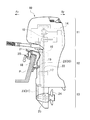
図1は、本発明に係る船外機10の概略構成例を示す左側面図である。この場合、船外機10は図示のように、その前部側にて船体の後尾板Pに固定されている。なお、以下の説明中で各図において必要に応じて、船外機10の前方を矢印Frにより、後方を矢印Rrにより示し、また船外機10の側方右側を矢印Rにより、側方左側を矢印Lによりそれぞれ示す。
Hereinafter, preferred embodiments of an outboard motor propulsion casing according to the present invention will be described with reference to the drawings.
FIG. 1 is a left side view showing a schematic configuration example of an outboard motor 10 according to the present invention. In this case, the outboard motor 10 is fixed to the rear plate P of the hull on the front side as shown. In the following description, the front of the outboard motor 10 is indicated by an arrow Fr, the rear is indicated by an arrow Rr, and the lateral right side of the outboard motor 10 is indicated by an arrow R as required. Are indicated by arrows L, respectively.

船外機10の全体構成において、上部から下部へエンジンユニット11、ミッドユニット12及びロアユニット13が順に配置構成される。エンジンユニット11においてエンジン14はエンジンベースを介して、そのクランクシャフト15が鉛直方向を向くように縦置きに搭載支持される。なお、エンジン14としては、例えばV型多気筒エンジンを採用可能である。ミッドユニット12は、アッパマウント16及びロアマウント17を介して、スイベルブラケット18に設定された支軸19のまわりに一体に回動可能となるように支持される。スイベルブラケット18の左右両側にはクランプブラケット20が設けられ、このクランプブラケット20を介して船体の後尾板Pに固定される。スイベルブラケット20は、左右方向に設定されたチルト軸21のまわりに上下方向に回動可能に支持される。   In the overall configuration of the outboard motor 10, the engine unit 11, the mid unit 12, and the lower unit 13 are sequentially arranged from the upper part to the lower part. In the engine unit 11, the engine 14 is mounted and supported vertically through the engine base so that the crankshaft 15 faces the vertical direction. For example, a V-type multi-cylinder engine can be employed as the engine 14. The mid unit 12 is supported via an upper mount 16 and a lower mount 17 so as to be integrally rotatable around a support shaft 19 set on the swivel bracket 18. Clamp brackets 20 are provided on the left and right sides of the swivel bracket 18, and are fixed to the rear plate P of the hull via the clamp brackets 20. The swivel bracket 20 is supported so as to be rotatable in the vertical direction around a tilt shaft 21 set in the horizontal direction.

ミッドユニット12において、クランクシャフト15の下端部に連結するドライブシャフト22が上下方向に貫通配置され、このドライブシャフト22の駆動力が、ロアユニット13のギアケース内の後述するプロペラシャフトに伝達されるようになっている。ドライブシャフト22の前側には、前後進の切換等を行うためのシフトロッド23が上下方向に平行配置される。シフトロッド23は後述するように、上部シフトロッド30と下部シフトロッド31を含む。なお、ミッドユニット12は、ドライブシャフト22を収容するドライブシャフトハウジングを有している。また、ミッドユニット12にはエンジンユニット11を潤滑するためのオイルを貯留するオイルパンが配設される。   In the mid unit 12, a drive shaft 22 connected to the lower end portion of the crankshaft 15 is vertically disposed so that the driving force of the drive shaft 22 is transmitted to a propeller shaft described later in a gear case of the lower unit 13. It is like that. On the front side of the drive shaft 22, a shift rod 23 for performing forward / reverse switching or the like is arranged in parallel in the vertical direction. The shift rod 23 includes an upper shift rod 30 and a lower shift rod 31, as will be described later. The mid unit 12 has a drive shaft housing that houses the drive shaft 22. The mid unit 12 is provided with an oil pan for storing oil for lubricating the engine unit 11.

ロアユニット13において、ドライブシャフト22の駆動力によりプロペラ24を回転駆動する複数のギア等を含むギアケース25を有する。ミッドユニット12からそれぞれ下方へ延出したドライブシャフト22はそれ自体に取り付けたギアが、ギアケース25内のギアと噛合することで最終的にプロペラ24を回転させるが、シフトロッド23の作用でギアケース25内のギア装置の動力伝達経路を切り換える、即ちシフトするようになっているが、これらについては後述する。   The lower unit 13 includes a gear case 25 including a plurality of gears that rotate the propeller 24 by the driving force of the drive shaft 22. Each of the drive shafts 22 extending downward from the mid unit 12 causes the gear attached to itself to mesh with the gear in the gear case 25 to eventually rotate the propeller 24. The power transmission path of the gear device in the case 25 is switched, that is, shifted, which will be described later.

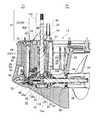
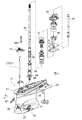
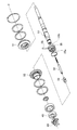
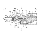
図3〜図6は、ロアユニット13の具体的な構成例を示している。図3はロアユニット13のプロペラ軸方向に沿った縦断面図、図4はロアユニット13のケーシングまわりの斜視図、図5及び図6はギアケース25内の主要構成をそれぞれ示す。なお、図5及び図6において、※印にて相互に接続されるものとする。先ず、図4のように一体形成されたケーシング26(下部ケーシング)においてミッドユニット12との合せ面付近にて上下に配置されたアンチスプラッシュプレート27及びアンチキャビテーションプレート28を有し、これらの下方へ延出した脚部29の下部には、前後方向に弾丸状を呈するように配置されたギアケース25を有する。   3 to 6 show specific configuration examples of the lower unit 13. 3 is a longitudinal sectional view of the lower unit 13 along the propeller axis direction, FIG. 4 is a perspective view around the casing of the lower unit 13, and FIGS. 5 and 6 show main components inside the gear case 25. In FIG. 5 and FIG. 6, it is assumed that they are connected to each other with * marks. First, an integrally formed casing 26 (lower casing) as shown in FIG. 4 has an anti-splash plate 27 and an anti-cavitation plate 28 that are arranged vertically near the mating surface with the mid unit 12, and below them. At the lower part of the extended leg portion 29, there is a gear case 25 arranged so as to exhibit a bullet shape in the front-rear direction.

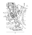
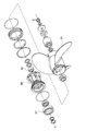
ケーシング26におけるギアケース25の弾丸状もしくは砲弾状の尖端部側にシフトロッド23が上下に挿通支持される。ここで、本実施形態では図2に示すようにシフトロッド23は、エンジンユニット11からミッドユニット12までの領域に延設される上部シフトロッド30と、図3のようにロアユニット13内に配置される下部シフトロッド31とで実質的に2分割構成される。なお、上部シフトロッド30は、アクチュエータ32の駆動力によりシフトリンク機構33を介して回転駆動され、その回転が更に一対の連結ギア34を介して下部シフトロッド31に伝達される。アクチュエータ32は、リモートコントロール装置を用いて作動制御されるようになっている。上部シフトロッド30及び下部シフトロッド31相互の連結部は、ケーシング26の上面に固定されるシフトロッドハウジング35によって保持されるようになっている。図3に示されるようにシフトロッド23、即ち下部シフトロッド31は、プロペラシャフト36の軸線と交差する位置まで垂設される。   A shift rod 23 is vertically inserted and supported on the bullet-like or bullet-like pointed end side of the gear case 25 in the casing 26. Here, in this embodiment, as shown in FIG. 2, the shift rod 23 is arranged in the upper shift rod 30 extending in the region from the engine unit 11 to the mid unit 12 and in the lower unit 13 as shown in FIG. The lower shift rod 31 is substantially divided into two parts. The upper shift rod 30 is rotationally driven via the shift link mechanism 33 by the driving force of the actuator 32, and the rotation is further transmitted to the lower shift rod 31 via a pair of connecting gears 34. The actuator 32 is controlled to operate using a remote control device. The connecting portion between the upper shift rod 30 and the lower shift rod 31 is held by a shift rod housing 35 fixed to the upper surface of the casing 26. As shown in FIG. 3, the shift rod 23, that is, the lower shift rod 31 is suspended up to a position that intersects the axis of the propeller shaft 36.

また、図3に示されるようにケーシング26における脚部29の前後方向略中央部付近には、ドライブシャフト22が挿通支持される。この場合、ドライブシャフト22は、脚部29の上部付近にて例えば背合せ型テーパローラベアリング37を介して、ケーシング26内で回転自在に支持され、その下端部がギアケース25内に到達するように垂設される。ドライブシャフト22におけるテーパローラベアリング37の下方部位には、螺旋状もしくはスパイラル状の凹溝38が刻設されており、この凹溝38の周囲にはドライブシャフト22の外周面との間に微少隙間をあけてカラー39が嵌着する。   Further, as shown in FIG. 3, the drive shaft 22 is inserted and supported in the vicinity of a substantially central portion in the front-rear direction of the leg portion 29 in the casing 26. In this case, the drive shaft 22 is rotatably supported in the casing 26 near the upper portion of the leg portion 29 via, for example, a back-to-back tapered roller bearing 37 so that the lower end portion thereof reaches the gear case 25. Is suspended. A spiral or spiral groove 38 is formed in the drive shaft 22 below the tapered roller bearing 37, and a minute gap is formed between the groove 38 and the outer peripheral surface of the drive shaft 22. The collar 39 is fitted with a gap.

ドライブシャフト22が回転することでスパイラル状の凹溝38は、オイル送給もしくはオイルポンプ機能を有し、ケーシング26内の潤滑を要する主要部位、部材に潤滑オイルを供給すべくオイル循環経路が形成される。なお、エンジンユニット11に対する潤滑用オイルポンプは、この凹溝38によるものとは別個に配置構成される。   As the drive shaft 22 rotates, the spiral groove 38 has an oil feeding or oil pump function, and an oil circulation path is formed to supply lubricating oil to the main parts and members that require lubrication in the casing 26. Is done. The lubricating oil pump for the engine unit 11 is arranged separately from the groove 38.

ケーシング26の上面においてドライブシャフト22に軸着するかたちで、冷却水ポンプ40が取り付けられる。この冷却水ポンプ40は、船外機10外部の水中から水を取り込んで、エンジンユニット11側に冷却水を供給する。この場合、図4のようにケーシング26の下部前側付近に水取入口41が設けられ、詳細な図示は省略するが、ケーシング26内部において冷却水ポンプ40及び水取入口41間が冷却水路68によって接続される。なお、水取入口41には異物等に対するフィルタ機能を有するカバー42が被着する。水取入口41は図3に示されるように、前後方向でドライブシャフト22と下部シフトロッド31との間に配置される。   A cooling water pump 40 is attached so as to be pivotally attached to the drive shaft 22 on the upper surface of the casing 26. The cooling water pump 40 takes water from the water outside the outboard motor 10 and supplies the cooling water to the engine unit 11 side. In this case, as shown in FIG. 4, a water intake 41 is provided near the lower front side of the casing 26, and detailed illustration is omitted, but the cooling water path 68 is provided between the cooling water pump 40 and the water intake 41 inside the casing 26. Connected. Note that a cover 42 having a filter function against foreign substances and the like is attached to the water intake port 41. As shown in FIG. 3, the water intake 41 is disposed between the drive shaft 22 and the lower shift rod 31 in the front-rear direction.

冷却水ポンプ40において図3及び図4に示すように、ドライブシャフト22にインペラ43が固定され、インペラ43はポンプケース44内に収容される。ドライブシャフト22が回転することで冷却水ポンプ40から加圧した冷却水が吐出され、その冷却水は冷却水パイプ45を介して送給され、最終的にエンジンユニット11側に供給される。   As shown in FIGS. 3 and 4, the impeller 43 is fixed to the drive shaft 22 in the cooling water pump 40, and the impeller 43 is accommodated in the pump case 44. As the drive shaft 22 rotates, pressurized cooling water is discharged from the cooling water pump 40, and the cooling water is supplied through the cooling water pipe 45 and finally supplied to the engine unit 11 side.

ギアケース25において、図3のようにプロペラシャフト36が前後方向に沿って配置され、複数のベアリング46,47,48を介して回転自在に支持される。なお、これらのうちベアリング47,48はベアリングハウジング49内に保持される。ドライブシャフト22の下端部下方にて、プロペラシャフト21と同心且つ遊嵌状態で前後一対のフォワード(前進)ギア50及びリバース(後進)ギア51が、それぞれベアリング52,53を介して回転自在に支持される。これらフォワードギア50及びリバースギア51は、ドライブシャフト22の下端部に固定されたドライブギア54と常時噛合している。この例ではフォワードギア50は前方Fr側に、リバースギア51は後方Rr側にそれぞれ配置され、これらの間にドッグクラッチ55が配設される。   In the gear case 25, the propeller shaft 36 is disposed along the front-rear direction as shown in FIG. 3 and is rotatably supported via a plurality of bearings 46, 47, 48. Of these, the bearings 47 and 48 are held in a bearing housing 49. Below the lower end of the drive shaft 22, a pair of front and rear forward gears 50 and reverse (reverse) gears 51 are rotatably supported via bearings 52 and 53, respectively, concentrically with the propeller shaft 21 and loosely fitted. Is done. The forward gear 50 and the reverse gear 51 are always meshed with a drive gear 54 fixed to the lower end portion of the drive shaft 22. In this example, the forward gear 50 is disposed on the front Fr side and the reverse gear 51 is disposed on the rear Rr side, and a dog clutch 55 is disposed therebetween.

ドッグクラッチ55を介してフォワードギア50からプロペラシャフト36への動力伝達経路が形成されることで、プロペラ24が右回転し、船外機10は前進する。また、リバースギア51からプロペラシャフト36への動力伝達経路が形成されることで、プロペラ24が左回転し、船外機10は後進する。   By forming a power transmission path from the forward gear 50 to the propeller shaft 36 via the dog clutch 55, the propeller 24 rotates clockwise and the outboard motor 10 moves forward. Further, since the power transmission path from the reverse gear 51 to the propeller shaft 36 is formed, the propeller 24 rotates counterclockwise and the outboard motor 10 moves backward.

ドッグクラッチ55は概略中空円筒状を呈し、プロペラシャフト36に対してその軸方向に沿って所定ストロークスライド可能に嵌合する。ドッグクラッチ55の軸方向両端面部には、フォワードギア50及びリバースギア51のそれぞれ内周部に設けた係合部50a,51aと係合可能な係合部55a,55bを有する。また、プロペラシャフト36及びこれに嵌合するドッグクラッチ55の双方をそれらの直径方向に貫通する係止ピン56により、両者は回転方向には相互に固定される。なお、係止ピン56が貫通するプロペラシャフト36の貫通孔57は、その軸方向に長孔になっている。従って、ドッグクラッチ55はプロペラシャフト36に対して、図3に示されるニュートラル状態位置から前後いずれかにスライドすることで、フォワードギア50又はリバースギア51に係合する。   The dog clutch 55 has a substantially hollow cylindrical shape, and is fitted to the propeller shaft 36 so as to be slidable for a predetermined stroke along the axial direction thereof. Engaging portions 55 a and 55 b that can be engaged with engaging portions 50 a and 51 a provided on the inner peripheral portions of the forward gear 50 and the reverse gear 51, respectively, are provided at both axial end surfaces of the dog clutch 55. The propeller shaft 36 and the dog clutch 55 fitted to the propeller shaft 36 are fixed to each other in the rotational direction by a locking pin 56 penetrating in the diametrical direction. A through hole 57 of the propeller shaft 36 through which the locking pin 56 passes is a long hole in the axial direction. Therefore, the dog clutch 55 is engaged with the forward gear 50 or the reverse gear 51 by sliding either forward or backward from the neutral state position shown in FIG.

プロペラシャフト36には図3に示されるように、コネクタロッド58が内挿され、このコネクタロッド58の一端側(後方Rr側)に係止ピン56が直交方向に結合する。コネクタロッド58の他端側(前方Fr側)には、スライドガイド60内でスライド可能に装着されたシフトスライダ59が連結される。このシフトスライダ59は、下部シフトロッド31の下端部に取り付けたシフトヨーク61と係合し、後述するように下部シフトロッド31の回転でシフトスライダ59、従ってドッグクラッチ55をスライドさせる。そして、ドッグクラッチ55がフォワードギア50又はリバースギア51に選択的に係合することで、ドライブシャフト22の駆動力をプロペラシャフト36に伝達させるようになっている。   As shown in FIG. 3, a connector rod 58 is inserted into the propeller shaft 36, and a locking pin 56 is coupled to one end side (rear side Rr side) of the connector rod 58 in the orthogonal direction. A shift slider 59 slidably mounted in the slide guide 60 is connected to the other end side (front Fr side) of the connector rod 58. The shift slider 59 engages with a shift yoke 61 attached to the lower end portion of the lower shift rod 31, and the shift slider 59 and thus the dog clutch 55 are slid by the rotation of the lower shift rod 31, as will be described later. The dog clutch 55 is selectively engaged with the forward gear 50 or the reverse gear 51 so that the driving force of the drive shaft 22 is transmitted to the propeller shaft 36.

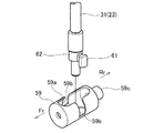
ここで図7は、スライドガイド60に装着されたシフトスライダ59まわりを示している。また、図8はシフトスライダ59とシフトヨーク61の関係を示す。これらの図を参照して、シフトスライダ59は概略円柱状を呈し、下部シフトロッド31の下端部が挿入し得るように円柱の側周面には、挿入孔59aがその円柱軸方向と直交方向に貫通形成される。また、挿入孔59aと繋がるようにその左右両側に、シフトヨーク61を収容可能に形成された係合部59bを有する。更に、シフトスライダ59の実装時には後側となる円柱軸方向の一端側には、コネクタロッド58の他端側(前方Fr側)との連結部59cを有する。   Here, FIG. 7 shows the periphery of the shift slider 59 attached to the slide guide 60. FIG. 8 shows the relationship between the shift slider 59 and the shift yoke 61. Referring to these drawings, the shift slider 59 has a substantially cylindrical shape, and an insertion hole 59a is formed in a direction perpendicular to the cylinder axis direction on the side peripheral surface of the cylinder so that the lower end of the lower shift rod 31 can be inserted. Is formed through. Moreover, it has the engaging part 59b formed so that the shift yoke 61 could be accommodated in the both right and left sides so that it might connect with the insertion hole 59a. Furthermore, a connecting portion 59c with the other end side (front Fr side) of the connector rod 58 is provided on one end side in the cylindrical axis direction which is the rear side when the shift slider 59 is mounted.

シフトヨーク61は図8に示されるように、下部シフトロッド31の下端部に固定されたアダプタ62に支持される。下部シフトロッド31の下端部をシフトスライダ59の挿入孔59aに挿入することで、シフトヨーク61が左右いずれかの係合部59bに収容される。シフトヨーク61の係合部59bと接触する外周面は円弧状もしくは湾曲状に形成され、両者は滑らかに接触する。図示例では左側の係合部59bにシフトヨーク61が係合するが、下部シフトロッド31を180°右旋させることで、右側の係合部59bに係合させることができる。   As shown in FIG. 8, the shift yoke 61 is supported by an adapter 62 fixed to the lower end portion of the lower shift rod 31. By inserting the lower end portion of the lower shift rod 31 into the insertion hole 59a of the shift slider 59, the shift yoke 61 is accommodated in either the left or right engaging portion 59b. The outer peripheral surface that contacts the engaging portion 59b of the shift yoke 61 is formed in an arc shape or a curved shape, and both are in smooth contact. In the illustrated example, the shift yoke 61 is engaged with the left engagement portion 59b, but the lower shift rod 31 can be engaged with the right engagement portion 59b by rotating 180 ° to the right.

スライドガイド60はその本体の基本形状が中空円筒状を呈し、図3のようにギアケース25の弾丸状もしくは砲弾状の尖端部に配置され、シフトスライダ59をスライド可能に収容するガイド孔60aを有する。スライドガイド60の一端側(後方Rr側)にはフランジ部60bを有し、このフランジ部60bでケーシング26の内壁に突き当てするかたちで位置決め固定されるようになっている。また、スライドガイド60の外周面とフランジ部60bとの間には、その軸方向に沿ってリブ60cが付設される。このリブ60cはスライドガイド60の左右両側において平面視で山型状に形成され、スライドガイド60全体として相当程度の剛性強度を確保している。右側又は左側に配置されるシフトヨーク61の対応部位には図7に示されるように、スライドガイド60のスライド方向に沿って切欠き60dが形成され、シフトヨーク61との相互干渉が生じないようにしている。   The basic shape of the slide guide 60 has a hollow cylindrical shape, and is arranged at the bullet-like or bullet-like tip of the gear case 25 as shown in FIG. 3, and has a guide hole 60a for slidably receiving the shift slider 59. Have. A flange portion 60b is provided on one end side (rear side Rr side) of the slide guide 60, and the flange portion 60b is positioned and fixed so as to abut against the inner wall of the casing 26. Further, a rib 60c is provided along the axial direction between the outer peripheral surface of the slide guide 60 and the flange portion 60b. The rib 60c is formed in a mountain shape in plan view on both the left and right sides of the slide guide 60, and the rigidity of the slide guide 60 as a whole is ensured to a considerable degree of rigidity. As shown in FIG. 7, a notch 60 d is formed in the corresponding portion of the shift yoke 61 arranged on the right side or the left side along the sliding direction of the slide guide 60 so that mutual interference with the shift yoke 61 does not occur. I have to.

前述のようにロアユニット13のケーシング26は、その尖端が前方を向きその内部にプロペラシャフト36を支持する下部のギアケース25と、このギアケース25から上方に延びてエンジン側との接続部を備え、平面視にて前後に長い略流線形に形成された脚部29とで構成される。そして、脚部29はその内部にドライブシャフト22及びシフトロッド23、即ち下部シフトロッド31を収容して略垂直に延びる収容空間が設けられると共に、脚部29の前縁が側面視でギアケース25の尖端と一致するように少なくとも下部を前方に延出する。脚部29はまた、図3に示されるように全体として、ミッドユニット12の本体ケーシング12a(上部ケーシング)よりも前方へ突出するかたちで延出する。   As described above, the casing 26 of the lower unit 13 has a lower gear case 25 that has a pointed end facing forward and a propeller shaft 36 supported therein, and a connection portion with the engine side that extends upward from the gear case 25. And leg portions 29 formed in a substantially streamline shape that is long in the front-rear direction in plan view. The leg 29 is provided therein with a housing space that accommodates the drive shaft 22 and the shift rod 23, that is, the lower shift rod 31, and extends substantially vertically, and the front edge of the leg 29 is a gear case 25 in a side view. Extend at least the lower part forward to coincide with the tip of As shown in FIG. 3, the leg 29 extends as a whole so as to protrude forward from the main body casing 12 a (upper casing) of the mid unit 12.

ここで、ケーシング26内の収容空間として図3を参照して、ドライブシャフト22を収容するドライブシャフト収容空間もしくは収容部63と、下部シフトロッド31を収容するシフトロッド収容空間もしくは収容部64と、プロペラシフト36を収容するプロペラシャフト収容空間もしくは収容部65とを含む。このうちドライブシャフト収容部63及びシフトロッド収容部64については金型構造上、ケーシング26の上部からスライド型で抜き成形され、またプロペラシャフト収容部65は、ケーシング26の後部からスライド型で抜き成形される。また、シフトロッド収容部64よりも前側の側面にて内側に凹む凹部66が形成される。この凹部66は別体のカバー67(図4等参照)によって覆われる。   Here, referring to FIG. 3 as a housing space in the casing 26, a drive shaft housing space or housing portion 63 for housing the drive shaft 22, a shift rod housing space or housing portion 64 for housing the lower shift rod 31, A propeller shaft accommodating space or accommodating portion 65 for accommodating the propeller shift 36. Of these, the drive shaft accommodating portion 63 and the shift rod accommodating portion 64 are punched from the upper portion of the casing 26 with a slide mold due to the mold structure, and the propeller shaft accommodating portion 65 is punched from the rear portion of the casing 26 with a slide mold. Is done. In addition, a recess 66 that is recessed inward on the side surface in front of the shift rod housing portion 64 is formed. The recess 66 is covered with a separate cover 67 (see FIG. 4 and the like).

次に、上記のように構成された船外機10における作動例を概略説明する。エンジンユニット11においてエンジン14が始動すると、そのクランクシャフト15の下端部に連結するドライブシャフト22が回転開始する。シフト機構を適宜操作することでドライブシャフト22の駆動力をロアユニット13のプロペラシャフト36に伝達させることができる。先ず、シフトヨーク61は図9にも示すようにシフトスライダ59の左側の係合部59bに係合するものとする。このときギアニュートラル状態となっており、ドッグクラッチ55はフォワードギア50及びリバースギア51のいずれにも係合しない。このニュートラル状態ではドライブシャフト22の駆動力はプロペラシャフト36に伝達されない。   Next, an operation example in the outboard motor 10 configured as described above will be schematically described. When the engine 14 is started in the engine unit 11, the drive shaft 22 connected to the lower end portion of the crankshaft 15 starts to rotate. The driving force of the drive shaft 22 can be transmitted to the propeller shaft 36 of the lower unit 13 by appropriately operating the shift mechanism. First, it is assumed that the shift yoke 61 is engaged with the engagement portion 59b on the left side of the shift slider 59 as shown in FIG. At this time, the gear neutral state is established, and the dog clutch 55 is not engaged with either the forward gear 50 or the reverse gear 51. In this neutral state, the driving force of the drive shaft 22 is not transmitted to the propeller shaft 36.

次に、リモートコントロール装置を用いてアクチュエータ32を作動制御し、シフトロッド23を回転駆動し、これにより下部シフトロッド31を図9の矢印で示すように右回転させる。シフトヨーク61も右回動することで、シフトスライダ59がシフトヨーク61に追従して矢印で示すように前方に移動する。このときドッグクラッチ55がプロペラシャフト36に対して、図9に示される位置から前方にスライドし、この場合にはフォワードギア50に係合する。これによりプロペラシャフト36、即ちプロペラ24が右回転し、船外機10は前進する。   Next, the actuator 32 is controlled by using a remote control device, and the shift rod 23 is rotationally driven, whereby the lower shift rod 31 is rotated clockwise as indicated by the arrow in FIG. When the shift yoke 61 also rotates to the right, the shift slider 59 follows the shift yoke 61 and moves forward as indicated by an arrow. At this time, the dog clutch 55 slides forward from the position shown in FIG. 9 with respect to the propeller shaft 36, and in this case, engages with the forward gear 50. As a result, the propeller shaft 36, that is, the propeller 24 rotates clockwise, and the outboard motor 10 moves forward.

一方、上記とは逆に下部シフトロッド31を図9の状態から左回転させると、シフトヨーク61も左回動する結果、ドッグクラッチ55が後方にスライドする。この場合にはドッグクラッチ55がリバースギア51に係合してプロペラ24が左回転し、船外機10は後進する。このようにアクチュエータ32を作動させて、シフトロッド23を介してシフトヨーク61を右又は左回動させるのに対応して、プロペラ24を正転又は逆転させることで、船外機10が前進又は後進する。   On the other hand, if the lower shift rod 31 is rotated counterclockwise from the state shown in FIG. 9, the dog yoke 55 slides backward as a result of the shift yoke 61 also rotating counterclockwise. In this case, the dog clutch 55 engages with the reverse gear 51, the propeller 24 rotates counterclockwise, and the outboard motor 10 moves backward. In this way, by operating the actuator 32 and rotating the shift yoke 61 to the right or left via the shift rod 23, the propeller 24 is rotated forward or reverse so that the outboard motor 10 moves forward or backward. Go backwards.

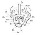
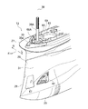
特に本発明では更に、図10を参照してユニット13のケーシング26の上面には、ミッドユニット12の本体ケーシング12aとの接合面69が形成される。本体ケーシング12aにはこの接合面69(接合面69Aを含む)と同形状の接合面が形成されている。両者が相互に接合した際には図3のようにケーシング26が本体ケーシング12aよりも前方に迫り出すかたちで配置される。上部シフトロッド30は図3に示されるように本体ケーシング12aの前外側に沿って垂設され、その下端部は下部シフトロッド31との連結部であるシフトロッドハウジング35によって保持される。なお、上部シフトロッド30の下端部は、基端ロッド30Aとして分離可能に構成される。   Particularly in the present invention, referring to FIG. 10, a joining surface 69 with the main body casing 12 a of the mid unit 12 is formed on the upper surface of the casing 26 of the unit 13. A joint surface having the same shape as the joint surface 69 (including the joint surface 69A) is formed in the main body casing 12a. When the two are joined to each other, the casing 26 is arranged so as to protrude forward from the main body casing 12a as shown in FIG. As shown in FIG. 3, the upper shift rod 30 is suspended along the front outer side of the main body casing 12 a, and the lower end portion thereof is held by a shift rod housing 35 that is a connecting portion with the lower shift rod 31. Note that the lower end portion of the upper shift rod 30 is configured to be separable as a proximal end rod 30A.

前述のように上部シフトロッド30及び下部シフトロッド31の連結部は、シフトロッドハウジング35によって保持される。このシフトロッドハウジング35は図3に示されるようにシフトロッド収容部64の上部開口を覆うように、ケーシング26の上面に固定される。接合面69の全体的形状は平面視で、例えば飛行機の翼断面形状のような概略流線形を呈し、その流線形の先端部が接合面69Aにより形成される。本発明ではシフトロッドハウジング35の上面に接合面69Aが形成される。即ち、シフトロッドハウジング35の上面に、上部ケーシング30及び下部ケーシング31の接合面69の一部である接合面69Aが設定される。接合面69の前部が更に前方へ延出し、この延出部35aが外部に露呈して外観を構成する。   As described above, the connecting portion of the upper shift rod 30 and the lower shift rod 31 is held by the shift rod housing 35. The shift rod housing 35 is fixed to the upper surface of the casing 26 so as to cover the upper opening of the shift rod accommodating portion 64 as shown in FIG. The overall shape of the joint surface 69 is a plan view and exhibits a substantially streamline shape, such as a cross-sectional shape of a wing of an airplane, and the streamline tip is formed by the joint surface 69A. In the present invention, a joining surface 69 </ b> A is formed on the upper surface of the shift rod housing 35. That is, a joining surface 69 </ b> A that is a part of the joining surface 69 of the upper casing 30 and the lower casing 31 is set on the upper surface of the shift rod housing 35. The front part of the joint surface 69 extends further forward, and this extended part 35a is exposed to the outside to constitute the appearance.

ここで、図12を参照してシフトロッドハウジング35は平面視で、概略三角形状(典型的には二等辺三角形)を呈し、その三角形の底辺側から前方へ向けて接合面69Aが配置される。この場合、図11のように接合面69が形成されているケーシング26との突当て部70に突き当てられ、シフトロッド収容部64の上部開口周縁に装着されるシールもしくはパッキン71を挟み込んでケーシング26の上面に固定される。基端ロッド30Aはシフトロッドハウジング35の上方から挿通して、シフトロッドハウジング35を貫通した基端ロッド30Aの下端には連結ギア34Aが取り付けられる。下部シフトロッド31は、上部シフトロッド30の前側にオフセットしてシフトロッド収容部64内に配置され、その上端がシフトロッドハウジング35により回転自在に支持される。また、下部シフトロッド31の上端部には、連結ギア34Aと噛合する他方の連結ギア34Bが取り付けられる。なお、シフトロッドハウジング35には図12に示されるように、シール及びカバー類72が装着されると共に、ニップル73等が取り付けられる。   Here, referring to FIG. 12, the shift rod housing 35 has a substantially triangular shape (typically an isosceles triangle) in a plan view, and a joint surface 69A is arranged from the bottom side of the triangle toward the front. . In this case, as shown in FIG. 11, the casing 70 is sandwiched with a seal or packing 71 that is abutted against the abutting portion 70 with the casing 26 on which the joining surface 69 is formed and is mounted on the periphery of the upper opening of the shift rod accommodating portion 64. 26 is fixed to the upper surface. The proximal end rod 30A is inserted from above the shift rod housing 35, and a connecting gear 34A is attached to the lower end of the proximal end rod 30A penetrating the shift rod housing 35. The lower shift rod 31 is offset in front of the upper shift rod 30 and is disposed in the shift rod accommodating portion 64, and the upper end thereof is rotatably supported by the shift rod housing 35. Further, the other connecting gear 34B that meshes with the connecting gear 34A is attached to the upper end portion of the lower shift rod 31. As shown in FIG. 12, the shift rod housing 35 is fitted with a seal and covers 72 and a nipple 73 and the like.

前述のように脚部29の内部にはエンジン側に冷却水を送給すべく、冷却水ポンプ40へ通じる冷却水路68が上下に延在する。この冷却水路68の下端部に水取入口41が設けられ、図3あるいは図11のように水取入口41から上方へ向けて、脚部29の左右両側に沿って独立した一対の冷却水路68が形成され、これらが合流してケーシング26の上面にて開口する。冷却水路68の上部開口は図11に示されるように、接合面69の内側領域に位置し、且つシフトロッドハウジング35との境界をなす突当て部70の後方に隣接配置される。そして、シフトロッドハウジング35の内側端縁(例えば、この例では二等辺三角形の底辺対応部)が前記冷却水路68に臨むように形成される。   As described above, the cooling water passage 68 leading to the cooling water pump 40 extends vertically in the leg portion 29 so as to supply the cooling water to the engine side. A water intake 41 is provided at the lower end of the cooling water channel 68, and a pair of independent cooling water channels 68 are formed along the left and right sides of the leg portion 29 upward from the water intake 41 as shown in FIG. Are formed, and they merge to open at the upper surface of the casing 26. As shown in FIG. 11, the upper opening of the cooling water channel 68 is located in the inner region of the joint surface 69 and is disposed adjacent to the rear of the abutting portion 70 that forms a boundary with the shift rod housing 35. The inner end edge of the shift rod housing 35 (for example, the base corresponding portion of an isosceles triangle in this example) is formed so as to face the cooling water channel 68.

次に、本発明の特徴的な作用効果について説明すると先ず、船外機10の仕様変更の際に、例えば特にギアケース25内のギア装置を大型化する場合等を考える。この場合、上部シフトロッド30及び下部シフトロッド31のオフセット量は基本的には大きくなる。
即ち、そのギア装置の前後方向長が長くなるのに伴い、下部シフトロッド31の上部シフトロッド30に対する前方へのオフセット量が大きくなるが、接合面69及び接合面69A自体は何ら変更が生じることない。この例では大型化した仕様変更後のロアユニット13であっても、これをミッドユニット12の本体ケーシング12aと適正に接合することができる。つまり、ミッドユニット12側の設計変更を伴うことなく船外機10の仕様変更に対応することができ、製造コスト等を大幅に低減することが可能になる。
Next, the characteristic effects of the present invention will be described. First, when changing the specifications of the outboard motor 10, for example, a case where the gear device in the gear case 25 is enlarged is considered. In this case, the offset amount of the upper shift rod 30 and the lower shift rod 31 is basically large.
That is, as the longitudinal length of the gear device becomes longer, the amount of forward offset of the lower shift rod 31 with respect to the upper shift rod 30 becomes larger, but the joining surface 69 and the joining surface 69A itself are changed. Absent. In this example, even the lower-sized lower unit 13 after the specification change can be appropriately joined to the main body casing 12a of the mid unit 12. That is, it is possible to cope with a change in the specifications of the outboard motor 10 without a design change on the mid unit 12 side, and it is possible to greatly reduce manufacturing costs and the like.

また、シフトロッドハウジング35の上面に設けた前方への延出部35aが外部に露呈して外観を構成する。このようにシフトロッドハウジング35の一部で外観を構成することで、外観形状における設計自由度が拡大し、より意匠性を向上することができる。   Further, a forward extending portion 35a provided on the upper surface of the shift rod housing 35 is exposed to the outside to form an appearance. By configuring the appearance with a part of the shift rod housing 35 in this manner, the degree of freedom in design of the appearance shape can be expanded, and the design can be further improved.

更に、ケーシング26とは別体のシフトロッドハウジング35を突当て部70にて突き当て配置する。この場合、仮にその突当て部70において隙間が発生した場合でも、シフトロッドハウジング35の内側端縁が冷却水路68に臨むように形成されるため、その隙間から浸入した水は基本的には冷却水路68へと流入する。即ち、シフトロッドハウジング35はシフトロッド収容部64の上部開口を覆っていることにも加え、そのような隙間から浸入した水がシフトロッド収容部64等に浸入することはなく、装置の保護を有効に実現する。   Further, a shift rod housing 35 separate from the casing 26 is disposed to abut against the abutment portion 70. In this case, even if a gap occurs in the abutting portion 70, the inner end edge of the shift rod housing 35 is formed so as to face the cooling water channel 68, so that the water that has entered through the gap is basically cooled. It flows into the water channel 68. That is, in addition to the shift rod housing 35 covering the upper opening of the shift rod housing portion 64, water that has entered from such a gap does not enter the shift rod housing portion 64 and the like, thus protecting the device. Realize effectively.

以上、本発明を種々の実施形態と共に説明したが、本発明はこれらの実施形態にのみ限定されるものではなく、本発明の範囲内で変更等が可能である。
外観を別部品で構成するシャフト部まわりに対しても本発明を有効に適用可能であり、上記実施形態の場合と同様な作用効果を得ることができる。
As mentioned above, although this invention was demonstrated with various embodiment, this invention is not limited only to these embodiment, A change etc. are possible within the scope of the present invention.
The present invention can also be effectively applied to the periphery of the shaft portion whose external appearance is composed of separate parts, and the same operational effects as in the case of the above embodiment can be obtained.

10 船外機、11 エンジンユニット、12 ミッドユニット、13 ロアユニット、14 エンジン、15 クランクシャフト、16 アッパマウント、17 ロアマウント、18 スイベルブラケット、19 支軸、20 クランプブラケット、21 チルト軸、22 ドライブシャフト、23 シフトロッド、24 プロペラ、25 ギアケース、26 ケーシング、27 アンチスプラッシュプレート、28 アンチキャビテーションプレート、29 脚部、30 上部シフトロッド、31 下部シフトロッド、32 アクチュエータ、33 シフトリンク機構、34 連結ギア、35 シフトロッドハウジング、36 プロペラシャフト、37 テーパローラベアリング、38 凹溝、39 カラー、40 冷却水ポンプ、41 水取入口、42 カバー、43 インペラ、44 ポンプケース、45 冷却水パイプ、46,47,48 ベアリング、49 ベアリングハウジング、50 フォワードギア、51 リバースギア、54 ドライブギア、55 ドッグクラッチ、56 係止ピン、57 貫通孔、58 コネクタロッド、59 シフトスライダ、60 スライドガイド、61 シフトヨーク、63 ドライブシャフト収容部、64 シフトロッド収容部、65 プロペラシャフト収容部、66 凹部、67 カバー、68 冷却水路、69,69A 接合面。 10 outboard motor, 11 engine unit, 12 mid unit, 13 lower unit, 14 engine, 15 crankshaft, 16 upper mount, 17 lower mount, 18 swivel bracket, 19 support shaft, 20 clamp bracket, 21 tilt shaft, 22 drive Shaft, 23 Shift rod, 24 Propeller, 25 Gear case, 26 Casing, 27 Anti-splash plate, 28 Anti-cavitation plate, 29 Leg, 30 Upper shift rod, 31 Lower shift rod, 32 Actuator, 33 Shift link mechanism, 34 Connection Gear, 35 Shift rod housing, 36 Propeller shaft, 37 Tapered roller bearing, 38 Groove, 39 Collar, 40 Cooling water pump, 41 Water inlet, 42 Cover , 43 Impeller, 44 Pump case, 45 Cooling water pipe, 46, 47, 48 Bearing, 49 Bearing housing, 50 Forward gear, 51 Reverse gear, 54 Drive gear, 55 Dog clutch, 56 Locking pin, 57 Through hole, 58 Connector rod, 59 Shift slider, 60 Slide guide, 61 Shift yoke, 63 Drive shaft accommodating part, 64 Shift rod accommodating part, 65 Propeller shaft accommodating part, 66 Recessed part, 67 Cover, 68 Cooling channel, 69, 69A Joining surface.

Claims (5)

船体の後部に支持されて、エンジン駆動力を伝達するドライブシャフトが垂設される上部ケーシング及び下部ケーシングを含む推進ケーシングを有する船外機において、前記下部ケーシング内に前記ドライブシャフト及びプロペラシャフトを切換可能に接続するギア装置と、該ギア装置の前方に配置され、その接続状態を切り換えるシフト装置と、このシフト装置を操作するためのシフトロッドとを備え、
前記シフトロッドを保持するシフトロッドハウジングの上面に、前記上部ケーシング及び前記下部ケーシングの接合面の一部が設定されることを特徴とする船外機の推進ケーシング。
In an outboard motor having a propulsion casing including an upper casing and a lower casing supported by a rear portion of a hull and provided with a drive shaft for transmitting an engine driving force, the drive shaft and the propeller shaft are switched in the lower casing. A gear device that can be connected, a shift device that is arranged in front of the gear device and switches the connection state, and a shift rod for operating the shift device,
A propulsion casing for an outboard motor, wherein a part of a joint surface between the upper casing and the lower casing is set on an upper surface of a shift rod housing that holds the shift rod.
前記シフトロッドは、前記上部ケーシングの前外側に沿って配置された上部シフトロッドとこの上部シフトロッドの前方にオフセットして前記下部ケーシング内に配置された下部シフトロッドとに分割構成され、前記上部シフトロッド及び前記下部シフトロッドの連結部に前記シフトロッドハウジングが配置されることを特徴とする請求項1に記載の船外機の推進ケーシング。   The shift rod is divided into an upper shift rod disposed along the front outer side of the upper casing and a lower shift rod disposed in the lower casing by being offset forward of the upper shift rod, and 2. The outboard motor propulsion casing according to claim 1, wherein the shift rod housing is disposed at a connecting portion between the shift rod and the lower shift rod. 前記シフトロッドハウジングは、前記下部シフトロッドの収容部の上部開口を覆うように前記下部ケーシングの上面に固定されると共に、その上面に、前記接合面の先端部が形成されることを特徴とする請求項2に記載の船外機の推進ケーシング。   The shift rod housing is fixed to an upper surface of the lower casing so as to cover an upper opening of a housing portion of the lower shift rod, and a front end portion of the joint surface is formed on the upper surface. The propulsion casing for the outboard motor according to claim 2. 前記シフトロッドハウジングの上面に形成される接合面の前部が前方へ延出し、この延出部が外観を構成することを特徴とする請求項1〜3のいずれか1項に記載の船外機の推進ケーシング。   The outboard according to any one of claims 1 to 3, wherein a front portion of a joint surface formed on an upper surface of the shift rod housing extends forward, and the extended portion constitutes an appearance. Machine propulsion casing. 前記下部シフトロッドの収容部の後方に冷却水路が隣接配置され、前記シフトロッドハウジングの内側端縁が前記冷却水路に臨むように形成されることを特徴とする請求項1〜4のいずれか1項に記載の船外機の推進ケーシング。   The cooling water channel is disposed adjacent to the rear of the receiving portion of the lower shift rod, and the inner edge of the shift rod housing is formed to face the cooling water channel. A propulsion casing for an outboard motor as described in the paragraph.
JP2011005102A 2011-01-13 2011-01-13 Outboard motor propulsion casing Active JP5630277B2 (en)

Priority Applications (1)

Application Number Priority Date Filing Date Title
JP2011005102A JP5630277B2 (en) 2011-01-13 2011-01-13 Outboard motor propulsion casing

Applications Claiming Priority (1)

Application Number Priority Date Filing Date Title
JP2011005102A JP5630277B2 (en) 2011-01-13 2011-01-13 Outboard motor propulsion casing

Publications (2)

Publication Number Publication Date
JP2012144186A true JP2012144186A (en) 2012-08-02
JP5630277B2 JP5630277B2 (en) 2014-11-26

Family

ID=46788223

Family Applications (1)

Application Number Title Priority Date Filing Date
JP2011005102A Active JP5630277B2 (en) 2011-01-13 2011-01-13 Outboard motor propulsion casing

Country Status (1)

Country Link
JP (1) JP5630277B2 (en)

Cited By (3)

* Cited by examiner, † Cited by third party
Publication number Priority date Publication date Assignee Title
US10293909B1 (en) 2017-11-06 2019-05-21 Yamaha Hatsudoki Kabushiki Kaisha Outboard motor
US11260947B2 (en) 2019-08-21 2022-03-01 Yamaha Hatsudoki Kabushiki Kaisha Outboard motor and marine vessel
EP4667348A1 (en) 2024-06-20 2025-12-24 Suzuki Motor Corporation Electric propulsion machine

Citations (3)

* Cited by examiner, † Cited by third party
Publication number Priority date Publication date Assignee Title
JPS619398A (en) * 1984-06-07 1986-01-16 アウトボード・マーリン・コーポレーシヨン Marine propeller with cathode protective measure
JP2008230337A (en) * 2007-03-19 2008-10-02 Suzuki Motor Corp Outboard motor gear case structure
JP2009286152A (en) * 2008-05-27 2009-12-10 Yamaha Motor Co Ltd Marine vessel propulsion unit

Patent Citations (3)

* Cited by examiner, † Cited by third party
Publication number Priority date Publication date Assignee Title
JPS619398A (en) * 1984-06-07 1986-01-16 アウトボード・マーリン・コーポレーシヨン Marine propeller with cathode protective measure
JP2008230337A (en) * 2007-03-19 2008-10-02 Suzuki Motor Corp Outboard motor gear case structure
JP2009286152A (en) * 2008-05-27 2009-12-10 Yamaha Motor Co Ltd Marine vessel propulsion unit

Cited By (3)

* Cited by examiner, † Cited by third party
Publication number Priority date Publication date Assignee Title
US10293909B1 (en) 2017-11-06 2019-05-21 Yamaha Hatsudoki Kabushiki Kaisha Outboard motor
US11260947B2 (en) 2019-08-21 2022-03-01 Yamaha Hatsudoki Kabushiki Kaisha Outboard motor and marine vessel
EP4667348A1 (en) 2024-06-20 2025-12-24 Suzuki Motor Corporation Electric propulsion machine

Also Published As

Publication number Publication date
JP5630277B2 (en) 2014-11-26

Similar Documents

Publication Publication Date Title
JP6186967B2 (en) Outboard gearbox
US20160185432A1 (en) Outboard motor
JP5630277B2 (en) Outboard motor propulsion casing
US9731803B2 (en) Outboard motor
JP2010221754A (en) Outboard motor
US11459079B2 (en) Ship propulsion machine
US9708044B2 (en) Outboard motor
JP4969165B2 (en) Outboard motor propulsion device
JP5541152B2 (en) Shift slider guide for outboard motor shift device
JP2012140081A (en) Shift device of outboard motor
US9022823B2 (en) Exhaust structure of outboard motor
JP6156106B2 (en) Outboard motor
JP2015517433A (en) Rotating shaft coupling structure and ship equipped with the same
JP6260425B2 (en) Outboard motor
JP7105554B2 (en) Outboard motor
JP5618759B2 (en) Ship speed reduction reverse rotation device
JP2012144187A (en) Casing of outboard motor lower unit
JP6287521B2 (en) Outboard motor
JP6260426B2 (en) Outboard motor
JP5867007B2 (en) Outboard motor cooling channel structure
US20130178121A1 (en) Exhaust structure of outboard motor
JP6260427B2 (en) Outboard motor
JP4866785B2 (en) Outboard motor
JP2010281220A (en) Rotating shaft support case structure
JP2009197887A (en) Actuator

Legal Events

Date Code Title Description
A621 Written request for application examination

Free format text: JAPANESE INTERMEDIATE CODE: A621

Effective date: 20130719

A977 Report on retrieval

Free format text: JAPANESE INTERMEDIATE CODE: A971007

Effective date: 20140319

A131 Notification of reasons for refusal

Free format text: JAPANESE INTERMEDIATE CODE: A131

Effective date: 20140408

A521 Written amendment

Free format text: JAPANESE INTERMEDIATE CODE: A523

Effective date: 20140523

TRDD Decision of grant or rejection written
A01 Written decision to grant a patent or to grant a registration (utility model)

Free format text: JAPANESE INTERMEDIATE CODE: A01

Effective date: 20140909

A61 First payment of annual fees (during grant procedure)

Free format text: JAPANESE INTERMEDIATE CODE: A61

Effective date: 20140922

R151 Written notification of patent or utility model registration

Ref document number: 5630277

Country of ref document: JP

Free format text: JAPANESE INTERMEDIATE CODE: R151