JP2012144187A - Casing of outboard motor lower unit - Google Patents

Casing of outboard motor lower unit Download PDF

Info

Publication number
JP2012144187A
JP2012144187A JP2011005108A JP2011005108A JP2012144187A JP 2012144187 A JP2012144187 A JP 2012144187A JP 2011005108 A JP2011005108 A JP 2011005108A JP 2011005108 A JP2011005108 A JP 2011005108A JP 2012144187 A JP2012144187 A JP 2012144187A
Authority
JP
Japan
Prior art keywords
casing
outboard motor
lower unit
gear case
leg
Prior art date
Legal status (The legal status is an assumption and is not a legal conclusion. Google has not performed a legal analysis and makes no representation as to the accuracy of the status listed.)
Pending
Application number
JP2011005108A
Other languages
Japanese (ja)
Inventor
Shuichi Sugiyama
修一 杉山
Current Assignee (The listed assignees may be inaccurate. Google has not performed a legal analysis and makes no representation or warranty as to the accuracy of the list.)
Suzuki Motor Corp
Original Assignee
Suzuki Motor Corp
Priority date (The priority date is an assumption and is not a legal conclusion. Google has not performed a legal analysis and makes no representation as to the accuracy of the date listed.)
Filing date
Publication date
Application filed by Suzuki Motor Corp filed Critical Suzuki Motor Corp
Priority to JP2011005108A priority Critical patent/JP2012144187A/en
Publication of JP2012144187A publication Critical patent/JP2012144187A/en
Pending legal-status Critical Current

Links

Images

Landscapes

  • General Details Of Gearings (AREA)

Abstract

【課題】軽量化及び低コスト化を図りながら、流体抵抗を有効に低減可能な船外機ロアユニットのケーシングを提供する。
【解決手段】尖端が前方を向きその内部にプロペラシャフト36を支持する下部のギアケース25と、ギアケース25から上方に延びてエンジン側との接続部を備え、平面視にて前後に長い略流線形に形成された脚部29とで構成される。ケーシング26における収容空間よりも前側の側面に内側に凹む凹部66を形成し、凹部66を覆う別体のカバー部材を備える。
【選択図】図3
A casing for an outboard motor lower unit capable of effectively reducing fluid resistance while reducing weight and cost.
A lower gear case 25 having a tip pointed forward and supporting a propeller shaft 36 therein, and a connection portion extending upward from the gear case 25 to the engine side, is substantially long in front and rear in plan view. It is comprised with the leg part 29 formed in the streamline. A concave portion 66 that is recessed inward is formed on the side surface in front of the accommodating space in the casing 26, and a separate cover member that covers the concave portion 66 is provided.
[Selection] Figure 3

Description

本発明は、ドライブシャフトと推進プロペラがギア装置を介して連結される船外機、特にそのケーシング構造に関する。   The present invention relates to an outboard motor in which a drive shaft and a propeller are connected via a gear device, and more particularly to a casing structure thereof.

この種の船外機において一般に、船体の後部に支持されてその下部が水中に没入可能としたロアユニットを備えている。例えば特許文献1に開示される船外機においてロアユニットは、正面視で略円形断面で前端に向かって先細形状とし、プロペラ軸を支持するようにした下部のギアケースと、このギアケースから上方に延びる脚部とを有している。   In general, this type of outboard motor is provided with a lower unit that is supported at the rear of the hull and whose lower part can be immersed in water. For example, in the outboard motor disclosed in Patent Document 1, the lower unit has a substantially circular cross section in a front view and a tapered shape toward the front end, and supports a propeller shaft. And a leg portion extending to the top.

船外機の燃焼向上策として水中に没するロアユニットの流体抵抗を低減することが考えられる。船外機のロアユニットの流体抵抗を低減する方法として、このロアユニットの下部に設けたギアケースの先端部形状及び船外機本体と接続する脚部を、より鋭角的な流線形にすることが考えられる。この方法はギアケースの尖端及び脚部を前方へ延出するためにギアケース及び脚部の前後長が長くなる。ギアケースの前方への延出部のようにプロペラ軸と平行な部分は加工によって駄肉の削除が可能である。   As a measure for improving the combustion of the outboard motor, it is conceivable to reduce the fluid resistance of the lower unit submerged in water. As a method of reducing the fluid resistance of the lower unit of the outboard motor, the shape of the tip of the gear case provided at the lower part of the lower unit and the leg portion connected to the outboard motor main body are made to have a sharper streamline. Can be considered. In this method, the front and rear lengths of the gear case and the leg are increased in order to extend the tip and the leg of the gear case forward. Parts that are parallel to the propeller shaft, such as the forward extension of the gear case, can be removed by machining.

特許第3537547号公報Japanese Patent No. 3537547

しかしながら、ロアユニットのケースはダイキャストにより一体成型するのが一般的であり、脚部の前方への延出部の駄肉を減らすために空洞を広げるのは成型型の構造が複雑化し、生産性が悪くなってしまいコストアップの一因になる。また、前方への延出部の駄肉部はロアユニットの重量を増加させて、流線形にした効果を相殺してしまうばかりか、ロアユニットの重量が増えた分材料費も増えて却ってコストが嵩む結果を招く。   However, the lower unit case is generally molded by die-casting, and the cavity is widened to reduce the waste of the extension part to the front of the leg part. It becomes a cause of cost increase because of worsening of the nature. In addition, the waste portion of the forward extension part increases the weight of the lower unit and offsets the streamlined effect, and the material cost also increases due to the increased weight of the lower unit. Results in a bulky result.

本発明はかかる実情に鑑み、軽量化及び低コスト化を図りながら、流体抵抗を有効に低減可能な船外機ロアユニットのケーシングを提供することを目的とする。   An object of the present invention is to provide a casing for an outboard motor lower unit capable of effectively reducing fluid resistance while achieving weight reduction and cost reduction.

本発明の船外機ロアユニットのケーシングは、船体の後部に支持されてその下部が水中に没入可能とされるロアユニットを有する船外機において、前記ロアユニットのケーシングは、尖端が前方を向きその内部にプロペラシャフトを支持する下部のギアケースと、このギアケースから上方に延びてエンジン側との接続部を備え、平面視にて前後に長い略流線形に形成された脚部とで構成され、前記脚部はその内部にドライブシャフト及びシフトロッドを収容して略垂直に延びる収容空間が設けられると共に、前記脚部の前縁が側面視で前記ギアケースの尖端と一致するように少なくとも下部を前方に延出し、前記ケーシングにおける前記収容空間よりも前側の側面に内側に凹む凹部を形成し、この凹部を覆う別体のカバー部材を備えたことを特徴とする。   The casing of the outboard motor lower unit according to the present invention is an outboard motor having a lower unit that is supported by the rear part of the hull and whose lower part can be immersed in water. It consists of a lower gear case that supports the propeller shaft inside, and a leg portion that extends upward from this gear case and has a connection portion with the engine side, and is formed in a substantially streamline shape that is long in the front and rear directions. The leg portion is provided with a housing space that accommodates the drive shaft and the shift rod therein and extends substantially vertically, and at least the front edge of the leg portion coincides with the tip of the gear case in a side view. A lower part is extended forward, a recessed part recessed inward is formed on a side surface in front of the housing space in the casing, and a separate cover member for covering the recessed part is provided. And butterflies.

また、本発明の船外機ロアユニットのケーシングにおいて、前記脚部はその前縁が側面視で上部よりも下部が前方に延出され、前記凹部は前記ギアケースの前端に隣接した下側基端部に配置されることを特徴とする。   Further, in the casing of the outboard motor lower unit according to the present invention, the leg portion has a front edge extending forward from the upper portion in the side view, and the concave portion is a lower base adjacent to the front end of the gear case. It is arranged at the end.

また、本発明の船外機ロアユニットのケーシングにおいて、前記凹部内に犠牲金属を配置すると共に、この凹部内外間で水が出入りするように構成したことを特徴とする。   The casing of the outboard motor lower unit according to the present invention is characterized in that a sacrificial metal is disposed in the recess and water enters and exits between the inside and outside of the recess.

また、本発明の船外機ロアユニットのケーシングにおいて、前記脚部の内部には前記エンジン側に冷却水を送給するための冷却水通路が上下に延在し、前記凹部の後側において前記冷却水通路の下端部に位置する水取入口を有することを特徴とする。   Further, in the casing of the outboard motor lower unit according to the present invention, a cooling water passage for supplying cooling water to the engine side extends vertically inside the leg portion, and the rear side of the concave portion It has the water intake located in the lower end part of a cooling water channel | path, It is characterized by the above-mentioned.

本発明によれば、凹部を設けることで駄肉を削除し、凹部対応部分の材料費用が減るため、低コスト化を図ることができる。この場合、凹部をカバーにより覆うことで凹部の後側に配置された水取入口に対する乱流の影響を最小限に抑制することができる。
また、凹部内に犠牲金属が配置することで、ケーシングに対して有効且つ適正な電蝕保護効果を得ることができる。
According to the present invention, by providing the concave portion, the waste is removed and the material cost of the concave portion corresponding portion is reduced, so that the cost can be reduced. In this case, the influence of the turbulent flow on the water intake port arranged on the rear side of the recess can be minimized by covering the recess with the cover.
In addition, by arranging the sacrificial metal in the recess, an effective and appropriate electrolytic corrosion protection effect can be obtained for the casing.

本発明に係る船外機の全体概略構成例を示す左側面図である。1 is a left side view showing an overall schematic configuration example of an outboard motor according to the present invention. 本発明に係る船外機のエンジンユニットまわりの前方斜視図である。FIG. 3 is a front perspective view around the engine unit of the outboard motor according to the present invention. 本発明に係る船外機ロアユニットの内部構成例を示す断面図である。It is sectional drawing which shows the internal structural example of the outboard motor lower unit which concerns on this invention. 本発明に係る船外機ロアユニットの分解斜視図である。It is a disassembled perspective view of the outboard motor lower unit which concerns on this invention. 本発明に係る船外機ロアユニットのギアケースの主要構成を示す分解斜視図である。It is a disassembled perspective view which shows the main structures of the gear case of the outboard motor lower unit which concerns on this invention. 本発明に係る船外機ロアユニットのギアケースの主要構成を示す分解斜視図である。It is a disassembled perspective view which shows the main structures of the gear case of the outboard motor lower unit which concerns on this invention. 本発明に係る船外機におけるスライドガイドに装着されたシフトスライダまわりを示す斜視図である。FIG. 3 is a perspective view showing the periphery of a shift slider mounted on a slide guide in the outboard motor according to the present invention. 本発明に係る船外機におけるシフトスライダとシフトヨークの関係を示す分解斜視図である。FIG. 3 is an exploded perspective view showing a relationship between a shift slider and a shift yoke in the outboard motor according to the present invention. 本発明に係る船外機ロアユニットにおけるプロペラシャフト軸線に沿う平断面図である。It is a plane sectional view which meets a propeller shaft axis in an outboard motor lower unit concerning the present invention. 本発明に係る船外機ロアユニットにおけるケーシング前部まわりの構成例を示す分解斜視図である。It is a disassembled perspective view which shows the structural example around the casing front part in the outboard motor lower unit which concerns on this invention. 本発明に係る船外機におけるチルトアップ時の作用を示す図である。It is a figure which shows the effect | action at the time of the tilt up in the outboard motor which concerns on this invention.

以下、図面に基づき、本発明における船外機ロアユニットのケーシングの好適な実施の形態を説明する。
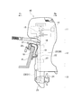
図1は、本発明に係る船外機10の概略構成例を示す左側面図である。この場合、船外機10は図示のように、その前部側にて船体の後尾板Pに固定されている。なお、以下の説明中で各図において必要に応じて、船外機10の前方を矢印Frにより、後方を矢印Rrにより示し、また船外機10の側方右側を矢印Rにより、側方左側を矢印Lによりそれぞれ示す。
Hereinafter, preferred embodiments of a casing of an outboard motor lower unit according to the present invention will be described with reference to the drawings.
FIG. 1 is a left side view showing a schematic configuration example of an outboard motor 10 according to the present invention. In this case, the outboard motor 10 is fixed to the rear plate P of the hull on the front side as shown. In the following description, the front of the outboard motor 10 is indicated by an arrow Fr, the rear is indicated by an arrow Rr, and the lateral right side of the outboard motor 10 is indicated by an arrow R as required. Are indicated by arrows L, respectively.

船外機10の全体構成において、上部から下部へエンジンユニット11、ミッドユニット12及びロアユニット13が順に配置構成される。エンジンユニット11においてエンジン14はエンジンベースを介して、そのクランクシャフト15が鉛直方向を向くように縦置きに搭載支持される。なお、エンジン14としては、例えばV型多気筒エンジンを採用可能である。ミッドユニット12は、アッパマウント16及びロアマウント17を介して、スイベルブラケット18に設定された支軸19のまわりに一体に回動可能となるように支持される。スイベルブラケット18の左右両側にはクランプブラケット20が設けられ、このクランプブラケット20を介して船体の後尾板Pに固定される。スイベルブラケット20は、左右方向に設定されたチルト軸21のまわりに上下方向に回動可能に支持される。   In the overall configuration of the outboard motor 10, the engine unit 11, the mid unit 12, and the lower unit 13 are sequentially arranged from the upper part to the lower part. In the engine unit 11, the engine 14 is mounted and supported vertically through the engine base so that the crankshaft 15 faces the vertical direction. For example, a V-type multi-cylinder engine can be employed as the engine 14. The mid unit 12 is supported via an upper mount 16 and a lower mount 17 so as to be integrally rotatable around a support shaft 19 set on the swivel bracket 18. Clamp brackets 20 are provided on the left and right sides of the swivel bracket 18, and are fixed to the rear plate P of the hull via the clamp brackets 20. The swivel bracket 20 is supported so as to be rotatable in the vertical direction around a tilt shaft 21 set in the horizontal direction.

ミッドユニット12において、クランクシャフト15の下端部に連結するドライブシャフト22が上下方向に貫通配置され、このドライブシャフト22の駆動力が、ロアユニット13のギアケース内の後述するプロペラシャフトに伝達されるようになっている。ドライブシャフト22の前側には、前後進の切換等を行うためのシフトロッド23が上下方向に平行配置される。シフトロッド23は後述するように、上部シフトロッド30と下部シフトロッド31を含む。なお、ミッドユニット12は、ドライブシャフト22を収容するドライブシャフトハウジングを有している。また、ミッドユニット12にはエンジンユニット11を潤滑するためのオイルを貯留するオイルパンが配設される。   In the mid unit 12, a drive shaft 22 connected to the lower end portion of the crankshaft 15 is vertically disposed so that the driving force of the drive shaft 22 is transmitted to a propeller shaft described later in a gear case of the lower unit 13. It is like that. On the front side of the drive shaft 22, a shift rod 23 for performing forward / reverse switching or the like is arranged in parallel in the vertical direction. The shift rod 23 includes an upper shift rod 30 and a lower shift rod 31, as will be described later. The mid unit 12 has a drive shaft housing that houses the drive shaft 22. The mid unit 12 is provided with an oil pan for storing oil for lubricating the engine unit 11.

ロアユニット13において、ドライブシャフト22の駆動力によりプロペラ24を回転駆動する複数のギア等を含むギアケース25を有する。ミッドユニット12からそれぞれ下方へ延出したドライブシャフト22はそれ自体に取り付けたギアが、ギアケース25内のギアと噛合することで最終的にプロペラ24を回転させるが、シフトロッド23の作用でギアケース25内のギア装置の動力伝達経路を切り換える、即ちシフトするようになっているが、これらについては後述する。   The lower unit 13 includes a gear case 25 including a plurality of gears that rotate the propeller 24 by the driving force of the drive shaft 22. Each of the drive shafts 22 extending downward from the mid unit 12 causes the gear attached to itself to mesh with the gear in the gear case 25 to eventually rotate the propeller 24. The power transmission path of the gear device in the case 25 is switched, that is, shifted, which will be described later.

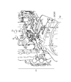
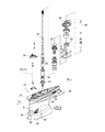
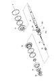
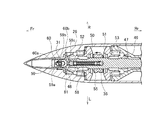
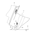
図3〜図6は、ロアユニット13の具体的な構成例を示している。図3はロアユニット13のプロペラ軸方向に沿った縦断面図、図4はロアユニット13のケーシングまわりの斜視図、図5及び図6はギアケース25内の主要構成をそれぞれ示す。なお、図5及び図6において、※印にて相互に接続されるものとする。先ず、図4のように一体形成されたケーシング26においてミッドユニット12との合せ面付近にて上下に配置されたアンチスプラッシュプレート27及びアンチキャビテーションプレート28を有し、これらの下方へ延出した脚部29の下部には、前後方向に弾丸状を呈するように配置されたギアケース25を有する。   3 to 6 show specific configuration examples of the lower unit 13. 3 is a longitudinal sectional view of the lower unit 13 along the propeller axis direction, FIG. 4 is a perspective view around the casing of the lower unit 13, and FIGS. 5 and 6 show main components inside the gear case 25. In FIG. 5 and FIG. 6, it is assumed that they are connected to each other with * marks. First, an integrally formed casing 26 as shown in FIG. 4 has an anti-splash plate 27 and an anti-cavitation plate 28 arranged vertically near the mating surface with the mid unit 12, and these legs extend downward. At the lower part of the portion 29, there is a gear case 25 arranged so as to exhibit a bullet shape in the front-rear direction.

ケーシング26におけるギアケース25の弾丸状もしくは砲弾状の尖端部側にシフトロッド23が上下に挿通支持される。ここで、本実施形態では図2に示すようにシフトロッド23は、エンジンユニット11からミッドユニット12までの領域に延設される上部シフトロッド30と、図3のようにロアユニット13内に配置される下部シフトロッド31とで実質的に2分割構成される。なお、上部シフトロッド30は、アクチュエータ32の駆動力によりシフトリンク機構33を介して回転駆動され、その回転が更に一対の連結ギア34を介して下部シフトロッド31に伝達される。アクチュエータ32は、リモートコントロール装置を用いて作動制御されるようになっている。上部シフトロッド30及び下部シフトロッド31相互の連結部は、ケーシング26の上面に固定されるシフトロッドハウジング35によって保持されるようになっている。図3に示されるようにシフトロッド23、即ち下部シフトロッド31は、プロペラシャフト36の軸線と交差する位置まで垂設される。   A shift rod 23 is vertically inserted and supported on the bullet-like or bullet-like pointed end side of the gear case 25 in the casing 26. Here, in this embodiment, as shown in FIG. 2, the shift rod 23 is arranged in the upper shift rod 30 extending in the region from the engine unit 11 to the mid unit 12 and in the lower unit 13 as shown in FIG. The lower shift rod 31 is substantially divided into two parts. The upper shift rod 30 is rotationally driven via the shift link mechanism 33 by the driving force of the actuator 32, and the rotation is further transmitted to the lower shift rod 31 via a pair of connecting gears 34. The actuator 32 is controlled to operate using a remote control device. The connecting portion between the upper shift rod 30 and the lower shift rod 31 is held by a shift rod housing 35 fixed to the upper surface of the casing 26. As shown in FIG. 3, the shift rod 23, that is, the lower shift rod 31 is suspended up to a position that intersects the axis of the propeller shaft 36.

また、図3に示されるようにケーシング26における脚部29の前後方向略中央部付近には、ドライブシャフト22が挿通支持される。この場合、ドライブシャフト22は、脚部29の上部付近にて例えば背合せ型テーパローラベアリング37を介して、ケーシング26内で回転自在に支持され、その下端部がギアケース25内に到達するように垂設される。ドライブシャフト22におけるテーパローラベアリング37の下方部位には、螺旋状もしくはスパイラル状の凹溝38が刻設されており、この凹溝38の周囲にはドライブシャフト22の外周面との間に微少隙間をあけてカラー39が嵌着する。   Further, as shown in FIG. 3, the drive shaft 22 is inserted and supported in the vicinity of a substantially central portion in the front-rear direction of the leg portion 29 in the casing 26. In this case, the drive shaft 22 is rotatably supported in the casing 26 near the upper portion of the leg portion 29 via, for example, a back-to-back tapered roller bearing 37 so that the lower end portion thereof reaches the gear case 25. Is suspended. A spiral or spiral groove 38 is formed in the drive shaft 22 below the tapered roller bearing 37, and a minute gap is formed between the groove 38 and the outer peripheral surface of the drive shaft 22. The collar 39 is fitted with a gap.

ドライブシャフト22が回転することでスパイラル状の凹溝38は、オイル送給もしくはオイルポンプ機能を有し、ケーシング26内の潤滑を要する主要部位、部材に潤滑オイルを供給すべくオイル循環経路が形成される。なお、エンジンユニット11に対する潤滑用オイルポンプは、この凹溝38によるものとは別個に配置構成される。   As the drive shaft 22 rotates, the spiral groove 38 has an oil feeding or oil pump function, and an oil circulation path is formed to supply lubricating oil to the main parts and members that require lubrication in the casing 26. Is done. The lubricating oil pump for the engine unit 11 is arranged separately from the groove 38.

ケーシング26の上面においてドライブシャフト22に軸着するかたちで、冷却水ポンプ40が取り付けられる。この冷却水ポンプ40は、船外機10外部の水中から水を取り込んで、エンジンユニット11側に冷却水を供給する。この場合、図10を参照してケーシング26の下部前側付近に水取入口41が設けられ、詳細な図示は省略するが、ケーシング26内部において冷却水ポンプ40及び水取入口41間が冷却水路によって接続される。なお、水取入口41には異物等に対するフィルタ機能を有するカバー42が被着する。水取入口41は図3に示されるように、前後方向でドライブシャフト22と下部シフトロッド31との間に配置される。   A cooling water pump 40 is attached so as to be pivotally attached to the drive shaft 22 on the upper surface of the casing 26. The cooling water pump 40 takes water from the water outside the outboard motor 10 and supplies the cooling water to the engine unit 11 side. In this case, referring to FIG. 10, a water intake 41 is provided near the lower front side of the casing 26, and although detailed illustration is omitted, a cooling water passage is provided between the cooling water pump 40 and the water intake 41 inside the casing 26. Connected. Note that a cover 42 having a filter function against foreign substances and the like is attached to the water intake port 41. As shown in FIG. 3, the water intake 41 is disposed between the drive shaft 22 and the lower shift rod 31 in the front-rear direction.

冷却水ポンプ40において図3及び図4に示すように、ドライブシャフト22にインペラ43が固定され、インペラ43はポンプケース44内に収容される。ドライブシャフト22が回転することで冷却水ポンプ40から加圧した冷却水が吐出され、その冷却水は冷却水パイプ45を介して送給され、最終的にエンジンユニット11側に供給される。   As shown in FIGS. 3 and 4, the impeller 43 is fixed to the drive shaft 22 in the cooling water pump 40, and the impeller 43 is accommodated in the pump case 44. As the drive shaft 22 rotates, pressurized cooling water is discharged from the cooling water pump 40, and the cooling water is supplied through the cooling water pipe 45 and finally supplied to the engine unit 11 side.

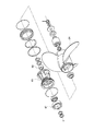
ギアケース25において、図3のようにプロペラシャフト36が前後方向に沿って配置され、複数のベアリング46,47,48を介して回転自在に支持される。なお、これらのうちベアリング47,48はベアリングハウジング49内に保持される。ドライブシャフト22の下端部下方にて、プロペラシャフト21と同心且つ遊嵌状態で前後一対のフォワード(前進)ギア50及びリバース(後進)ギア51が、それぞれベアリング52,53を介して回転自在に支持される。これらフォワードギア50及びリバースギア51は、ドライブシャフト22の下端部に固定されたドライブギア54と常時噛合している。この例ではフォワードギア50は前方Fr側に、リバースギア51は後方Rr側にそれぞれ配置され、これらの間にドッグクラッチ55が配設される。   In the gear case 25, the propeller shaft 36 is disposed along the front-rear direction as shown in FIG. 3 and is rotatably supported via a plurality of bearings 46, 47, 48. Of these, the bearings 47 and 48 are held in a bearing housing 49. Below the lower end of the drive shaft 22, a pair of front and rear forward gears 50 and reverse (reverse) gears 51 are rotatably supported via bearings 52 and 53, respectively, concentrically with the propeller shaft 21 and loosely fitted. Is done. The forward gear 50 and the reverse gear 51 are always meshed with a drive gear 54 fixed to the lower end portion of the drive shaft 22. In this example, the forward gear 50 is disposed on the front Fr side and the reverse gear 51 is disposed on the rear Rr side, and a dog clutch 55 is disposed therebetween.

ドッグクラッチ55を介してフォワードギア50からプロペラシャフト36への動力伝達経路が形成されることで、プロペラ24が右回転し、船外機10は前進する。また、リバースギア51からプロペラシャフト36への動力伝達経路が形成されることで、プロペラ24が左回転し、船外機10は後進する。   By forming a power transmission path from the forward gear 50 to the propeller shaft 36 via the dog clutch 55, the propeller 24 rotates clockwise and the outboard motor 10 moves forward. Further, since the power transmission path from the reverse gear 51 to the propeller shaft 36 is formed, the propeller 24 rotates counterclockwise and the outboard motor 10 moves backward.

ドッグクラッチ55は概略中空円筒状を呈し、プロペラシャフト36に対してその軸方向に沿って所定ストロークスライド可能に嵌合する。ドッグクラッチ55の軸方向両端面部には、フォワードギア50及びリバースギア51のそれぞれ内周部に設けた係合部50a,51aと係合可能な係合部55a,55bを有する。ドッグクラッチ55は、図3に示されるニュートラル状態位置から前後いずれかにスライドすることで、フォワードギア50又はリバースギア51に係合する。   The dog clutch 55 has a substantially hollow cylindrical shape, and is fitted to the propeller shaft 36 so as to be slidable for a predetermined stroke along the axial direction thereof. Engaging portions 55 a and 55 b that can be engaged with engaging portions 50 a and 51 a provided on the inner peripheral portions of the forward gear 50 and the reverse gear 51, respectively, are provided at both axial end surfaces of the dog clutch 55. The dog clutch 55 is engaged with the forward gear 50 or the reverse gear 51 by sliding either forward or backward from the neutral state position shown in FIG.

また、プロペラシャフト36及びこれに嵌合するドッグクラッチ55の双方をそれらの直径方向に貫通する係止ピン56により、両者は回転方向には相互に固定される。なお、係止ピン56が貫通するプロペラシャフト36の貫通孔57は、その軸方向に長孔になっている。従って、ドッグクラッチ55はプロペラシャフト36に対して、図3に示されるニュートラル状態位置から前後いずれかにスライドすることで、フォワードギア50又はリバースギア51に係合する。   The propeller shaft 36 and the dog clutch 55 fitted to the propeller shaft 36 are fixed to each other in the rotational direction by a locking pin 56 penetrating in the diametrical direction. A through hole 57 of the propeller shaft 36 through which the locking pin 56 passes is a long hole in the axial direction. Therefore, the dog clutch 55 is engaged with the forward gear 50 or the reverse gear 51 by sliding either forward or backward from the neutral state position shown in FIG.

プロペラシャフト36には図3に示されるように、コネクタロッド58が内挿され、このコネクタロッド58の一端側(後方Rr側)に係止ピン56が直交方向に結合する。コネクタロッド58の他端側(前方Fr側)には、スライドガイド60内でスライド可能に装着されたシフトスライダ59が連結される。このシフトスライダ59は、下部シフトロッド31の下端部に取り付けたシフトヨーク61と係合し、後述するように下部シフトロッド31の回転でシフトスライダ59、従ってドッグクラッチ55をスライドさせる。そして、ドッグクラッチ55がフォワードギア50又はリバースギア51に選択的に係合することで、ドライブシャフト22の駆動力をプロペラシャフト36に伝達させるようになっている。   As shown in FIG. 3, a connector rod 58 is inserted into the propeller shaft 36, and a locking pin 56 is coupled to one end side (rear side Rr side) of the connector rod 58 in the orthogonal direction. A shift slider 59 slidably mounted in the slide guide 60 is connected to the other end side (front Fr side) of the connector rod 58. The shift slider 59 engages with a shift yoke 61 attached to the lower end portion of the lower shift rod 31, and the shift slider 59 and thus the dog clutch 55 are slid by the rotation of the lower shift rod 31, as will be described later. The dog clutch 55 is selectively engaged with the forward gear 50 or the reverse gear 51 so that the driving force of the drive shaft 22 is transmitted to the propeller shaft 36.

ここで図7は、スライドガイド60に装着されたシフトスライダ59まわりを示している。また、図8はシフトスライダ59とシフトヨーク61の関係を示す。これらの図を参照して、シフトスライダ59は概略円柱状を呈し、下部シフトロッド31の下端部が挿入し得るように円柱の側周面には、挿入孔59aがその円柱軸方向と直交方向に貫通形成される。また、挿入孔59aと繋がるようにその左右両側に、シフトヨーク61を収容可能に形成された係合部59bを有する。更に、シフトスライダ59の実装時には後側となる円柱軸方向の一端側には、コネクタロッド58の他端側(前方Fr側)との連結部59cを有する。   Here, FIG. 7 shows the periphery of the shift slider 59 attached to the slide guide 60. FIG. 8 shows the relationship between the shift slider 59 and the shift yoke 61. Referring to these drawings, the shift slider 59 has a substantially cylindrical shape, and an insertion hole 59a is formed in a direction perpendicular to the cylinder axis direction on the side peripheral surface of the cylinder so that the lower end of the lower shift rod 31 can be inserted. Is formed through. Moreover, it has the engaging part 59b formed so that the shift yoke 61 could be accommodated in the both right and left sides so that it might connect with the insertion hole 59a. Furthermore, a connecting portion 59c with the other end side (front Fr side) of the connector rod 58 is provided on one end side in the cylindrical axis direction which is the rear side when the shift slider 59 is mounted.

シフトヨーク61は図8に示されるように、下部シフトロッド31の下端部に固定されたアダプタ62に支持される。下部シフトロッド31の下端部をシフトスライダ59の挿入孔59aに挿入することで、シフトヨーク61が左右いずれかの係合部59bに収容される。シフトヨーク61の係合部59bと接触する外周面は円弧状もしくは湾曲状に形成され、両者は滑らかに接触する。図示例では左側の係合部59bにシフトヨーク61が係合するが、下部シフトロッド31を180°右旋させることで、右側の係合部59bに係合させることができる。   As shown in FIG. 8, the shift yoke 61 is supported by an adapter 62 fixed to the lower end portion of the lower shift rod 31. By inserting the lower end portion of the lower shift rod 31 into the insertion hole 59a of the shift slider 59, the shift yoke 61 is accommodated in either the left or right engaging portion 59b. The outer peripheral surface that contacts the engaging portion 59b of the shift yoke 61 is formed in an arc shape or a curved shape, and both are in smooth contact. In the illustrated example, the shift yoke 61 is engaged with the left engagement portion 59b, but the lower shift rod 31 can be engaged with the right engagement portion 59b by rotating 180 ° to the right.

スライドガイド60はその本体の基本形状が中空円筒状を呈し、図3のようにギアケース25の弾丸状もしくは砲弾状の尖端部に配置され、シフトスライダ59をスライド可能に収容するガイド孔60aを有する。スライドガイド60の一端側(後方Rr側)にはフランジ部60bを有し、このフランジ部60bでケーシング26の内壁に突き当てするかたちで位置決め固定されるようになっている。また、スライドガイド60の外周面とフランジ部60bとの間には、その軸方向に沿ってリブ60cが付設される。このリブ60cはスライドガイド60の左右両側において平面視で山型状に形成され、スライドガイド60全体として相当程度の剛性強度を確保している。右側又は左側に配置されるシフトヨーク61の対応部位には図7等に示されるように、スライドガイド60のスライド方向に沿って切欠き60dが形成され、シフトヨーク61との相互干渉が生じないようにしている。   The basic shape of the slide guide 60 has a hollow cylindrical shape, and is arranged at the bullet-like or bullet-like tip of the gear case 25 as shown in FIG. 3, and has a guide hole 60a for slidably receiving the shift slider 59. Have. A flange portion 60b is provided on one end side (rear side Rr side) of the slide guide 60, and the flange portion 60b is positioned and fixed so as to abut against the inner wall of the casing 26. Further, a rib 60c is provided along the axial direction between the outer peripheral surface of the slide guide 60 and the flange portion 60b. The rib 60c is formed in a mountain shape in plan view on both the left and right sides of the slide guide 60, and the rigidity of the slide guide 60 as a whole is ensured to a considerable degree of rigidity. As shown in FIG. 7 and the like, a notch 60d is formed in the corresponding portion of the shift yoke 61 arranged on the right side or the left side along the sliding direction of the slide guide 60, and mutual interference with the shift yoke 61 does not occur. Like that.

次に、上記のように構成された船外機10における作動例を概略説明する。エンジンユニット11においてエンジン14が始動すると、そのクランクシャフト15の下端部に連結するドライブシャフト22が回転開始する。シフト機構を適宜操作することでドライブシャフト22の駆動力をロアユニット13のプロペラシャフト36に伝達させることができる。先ず、シフトヨーク61は図9にも示すようにシフトスライダ59の左側の係合部59bに係合するものとする。このときギアニュートラル状態となっており、ドッグクラッチ55はフォワードギア50及びリバースギア51のいずれにも係合しない。このニュートラル状態ではドライブシャフト22の駆動力はプロペラシャフト36に伝達されない。   Next, an operation example in the outboard motor 10 configured as described above will be schematically described. When the engine 14 is started in the engine unit 11, the drive shaft 22 connected to the lower end portion of the crankshaft 15 starts to rotate. The driving force of the drive shaft 22 can be transmitted to the propeller shaft 36 of the lower unit 13 by appropriately operating the shift mechanism. First, it is assumed that the shift yoke 61 is engaged with the engagement portion 59b on the left side of the shift slider 59 as shown in FIG. At this time, the gear neutral state is established, and the dog clutch 55 is not engaged with either the forward gear 50 or the reverse gear 51. In this neutral state, the driving force of the drive shaft 22 is not transmitted to the propeller shaft 36.

次に、リモートコントロール装置を用いてアクチュエータ32を作動制御し、シフトロッド23を回転駆動し、これにより下部シフトロッド31を図9の矢印で示すように右回転させる。シフトヨーク61も右回動することで、シフトスライダ59がシフトヨーク61に追従して矢印で示すように前方に移動する。このときドッグクラッチ55がプロペラシャフト36に対して、図9に示される位置から前方にスライドし、この場合にはフォワードギア50に係合する。これによりプロペラシャフト36、即ちプロペラ24が右回転し、船外機10は前進する。   Next, the actuator 32 is controlled by using a remote control device, and the shift rod 23 is rotationally driven, whereby the lower shift rod 31 is rotated clockwise as indicated by the arrow in FIG. When the shift yoke 61 also rotates to the right, the shift slider 59 follows the shift yoke 61 and moves forward as indicated by an arrow. At this time, the dog clutch 55 slides forward from the position shown in FIG. 9 with respect to the propeller shaft 36, and in this case, engages with the forward gear 50. As a result, the propeller shaft 36, that is, the propeller 24 rotates clockwise, and the outboard motor 10 moves forward.

一方、上記とは逆に下部シフトロッド31を図9の状態から左回転させると、シフトヨーク61も左回動する結果、ドッグクラッチ55が後方にスライドする。この場合にはドッグクラッチ55がリバースギア51に係合してプロペラ24が左回転し、船外機10は後進する。このようにアクチュエータ32を作動させて、シフトロッド23を介してシフトヨーク61を右又は左回動させるのに対応して、プロペラ24を正転又は逆転させることで、船外機10が前進又は後進する。   On the other hand, if the lower shift rod 31 is rotated counterclockwise from the state shown in FIG. 9, the dog yoke 55 slides backward as a result of the shift yoke 61 also rotating counterclockwise. In this case, the dog clutch 55 engages with the reverse gear 51, the propeller 24 rotates counterclockwise, and the outboard motor 10 moves backward. In this way, by operating the actuator 32 and rotating the shift yoke 61 to the right or left via the shift rod 23, the propeller 24 is rotated forward or reverse so that the outboard motor 10 moves forward or backward. Go backwards.

特に本発明では更に、前述のようにロアユニット13のケーシング26は、その尖端が前方を向きその内部にプロペラシャフト36を支持する下部のギアケース25と、このギアケース25から上方に延びてエンジン側との接続部を備え、平面視にて前後に長い略流線形に形成された脚部29とで構成される。そして、脚部29はその内部にドライブシャフト22及びシフトロッド23、即ち下部シフトロッド31を収容して略垂直に延びる収容空間が設けられると共に、脚部29の前縁が側面視でギアケース25の尖端と一致するように少なくとも下部を前方に延出する。脚部29はまた、図3に示されるように全体として、ミッドユニット12の本体ケーシング12aよりも前方へ突出するかたちで延出する。   In particular, in the present invention, as described above, the casing 26 of the lower unit 13 includes the lower gear case 25 whose tip end faces forward and the propeller shaft 36 is supported therein, and extends upward from the gear case 25 to the engine. The leg part 29 is provided with a connection part to the side and is formed in a substantially streamline shape that is long in the front-rear direction in plan view. The leg 29 is provided therein with a housing space that accommodates the drive shaft 22 and the shift rod 23, that is, the lower shift rod 31, and extends substantially vertically, and the front edge of the leg 29 is a gear case 25 in a side view. Extend at least the lower part forward to coincide with the tip of As shown in FIG. 3, the leg portion 29 also extends as a whole so as to protrude forward from the main body casing 12 a of the mid unit 12.

ここで、ケーシング26内の収容空間として図3に示されるように、ドライブシャフト22を収容するドライブシャフト収容空間もしくは収容部63と、下部シフトロッド31を収容するシフトロッド収容空間もしくは収容部64と、プロペラシフト36を収容するプロペラシャフト収容空間もしくは収容部65とを含む。このうちドライブシャフト収容部63及びシフトロッド収容部64については金型構造上、ケーシング26の上部からスライド型で抜き成形され、またプロペラシャフト収容部65は、ケーシング26の後部からスライド型で抜き成形される。成形上これらの収容部は、抜き勾配を確保するために基本的には先細に形成される一方、ケーシング26の外観形態において特にギアケース25の先端部と脚部29の繋がり部分は、流体抵抗を低減すべく滑らかに連続するように形成される。このため図3あるいは図4に一点鎖線により示されるように、シフトロッド収容部64の前側であって、プロペラシャフト収容部65の先端部上側付近の領域Sには成形上、駄肉が形成される。   Here, as shown in FIG. 3 as an accommodation space in the casing 26, a drive shaft accommodation space or accommodation portion 63 for accommodating the drive shaft 22, and a shift rod accommodation space or accommodation portion 64 for accommodating the lower shift rod 31 And a propeller shaft accommodating space or accommodating portion 65 for accommodating the propeller shift 36. Of these, the drive shaft accommodating portion 63 and the shift rod accommodating portion 64 are punched from the upper portion of the casing 26 with a slide mold due to the mold structure, and the propeller shaft accommodating portion 65 is punched from the rear portion of the casing 26 with a slide mold. Is done. In the molding, these accommodating portions are basically tapered in order to ensure a draft angle, whereas in the external form of the casing 26, particularly the connecting portion between the tip portion of the gear case 25 and the leg portion 29 is fluid resistance. It is formed to be smoothly continuous in order to reduce For this reason, as shown by a one-dot chain line in FIG. 3 or FIG. The

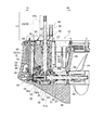
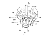
さて、本発明では図10に示されるように、ケーシング26におけるシフトロッド収容部64よりも前側の側面にて内側に凹む凹部66が形成される。この凹部66は別体のカバー67によって覆われる。この場合、凹部66は側面視で領域Sに略対応し、より具体的には図3等のようにその前縁が側面視で上部よりも下部が前方に延出する脚部29において、ギアケース26の前端に隣接した下側基端部に配置される。   In the present invention, as shown in FIG. 10, a concave portion 66 is formed that is recessed inward on the side surface of the casing 26 that is in front of the shift rod housing portion 64. The recess 66 is covered with a separate cover 67. In this case, the recess 66 substantially corresponds to the region S in a side view, and more specifically, in the leg portion 29 whose front edge extends forward from the upper side in a side view as shown in FIG. The case 26 is disposed at the lower base end adjacent to the front end.

図10に示されるように凹部66の適所、例えば凹部66の底部に固定用ネジ部68を設け、ボルト69によってカバー67が固定される。カバー67はプラスチック製であってよく、凹部66に被着した際、凹部66周辺のケーシング26外表面と滑らかに連なるように結合する。なお、ボルト69の装着部には栓70が埋め込まれ、滑らかな外表面を確保する。   As shown in FIG. 10, a fixing screw portion 68 is provided at an appropriate position of the recess 66, for example, at the bottom of the recess 66, and the cover 67 is fixed by the bolt 69. The cover 67 may be made of plastic, and when attached to the recess 66, the cover 67 is joined so as to be smoothly connected to the outer surface of the casing 26 around the recess 66. A plug 70 is embedded in the mounting portion of the bolt 69 to ensure a smooth outer surface.

凹部66内にはまた、犠牲金属71が配置され、この凹部66内外間で水が出入りするように構成される。図示を省略するが、例えばカバー67に適所に1又は複数の小孔を設け、この小孔を介して凹部66に水が出入可能とする。あるいは、凹部66と水取入口41とを相互に連通させることによっても可能である。この場合、凹部66の適所、例えば凹部66の角部に固定用ネジ部72を設け、ボルト73によって犠牲金属71が固定される。   A sacrificial metal 71 is also disposed in the recess 66, and is configured such that water enters and exits between the inside and the outside of the recess 66. Although illustration is omitted, for example, one or a plurality of small holes are provided at appropriate positions in the cover 67, and water can enter and leave the recess 66 through the small holes. Or it is also possible by making the recessed part 66 and the water intake 41 communicate mutually. In this case, a fixing screw portion 72 is provided at an appropriate position of the concave portion 66, for example, at a corner portion of the concave portion 66, and the sacrificial metal 71 is fixed by the bolt 73.

また、脚部29の内部にはエンジン側に冷却水を送給するための冷却水通路74が上下に延在する。この冷却水通路74の下端部に水取入口41が設けられる。この例では水取入口41から上方へ向けて、脚部29の左右両側に沿って独立して連通路が形成され、これらの連通路が合流して冷却水通路74となる。なお、水取入口41に被着する左右のカバー42は連結バー75を介して相互に結合される。この場合、連結バー75に固定用ネジ部76を設け、ボルト77によって固定される。ボルト77の装着部には栓78が埋め込まれる。   A cooling water passage 74 for supplying cooling water to the engine side extends vertically inside the leg portion 29. A water intake 41 is provided at the lower end of the cooling water passage 74. In this example, a communication path is formed independently along the left and right sides of the leg portion 29 from the water intake 41 upward, and these communication paths merge to form a cooling water path 74. Note that the left and right covers 42 attached to the water intake 41 are connected to each other via a connecting bar 75. In this case, the connecting bar 75 is provided with a fixing screw portion 76 and fixed by the bolt 77. A plug 78 is embedded in the mounting portion of the bolt 77.

次に、本発明の特徴的な作用効果について説明すると先ず、ケーシング26における駄肉が形成され得る領域Sに凹部66を設けることで、ケーシング26自体のみならずロアユニット13全体としても重量を大幅に減少する。前述のようにロアユニット13をミッドユニット12よりも前方へ延出させて、ケーシング26を流線形とすることにより、ロアユニット13の流体抵抗を低減するが、同時に上記のようにロアユニット13の重量軽減を図ることで流線形とした効果をより実効あらしめる。   Next, the characteristic effects of the present invention will be described. First, by providing the recess 66 in the region S where the sacrificial meat can be formed in the casing 26, the weight of not only the casing 26 itself but also the entire lower unit 13 is greatly increased. To decrease. As described above, the lower unit 13 extends forward from the mid unit 12 and the casing 26 is streamlined to reduce the fluid resistance of the lower unit 13. At the same time, as described above, By reducing the weight, the streamlined effect is more effective.

また、上記のように駄肉を削除することで、少なくとも凹部66対応部分の材料費用が減るため、低コスト化を図ることができる。
更に、凹部66はロアユニット13の下方付近に設けられ、船外機10全体においてチルト軸21(図1参照)から実質的に最も離れた部位に該当する。このような部位の駄肉を削除することで、チルト動作の際、チルト軸21まわりの回動時に負荷となる回転モーメントを小さくし、チルト駆動系の小型化が可能になる。
In addition, by removing the waste as described above, the material cost of at least the portion corresponding to the recess 66 is reduced, so that the cost can be reduced.
Further, the recess 66 is provided in the vicinity of the lower portion of the lower unit 13 and corresponds to a portion substantially farthest from the tilt shaft 21 (see FIG. 1) in the outboard motor 10 as a whole. By removing the thin wall at such a part, the rotational moment that becomes a load when rotating around the tilt shaft 21 during the tilt operation can be reduced, and the tilt drive system can be downsized.

また、上述のように凹部66はカバー67によって覆われる。凹部66をカバー67により覆うことで凹部66周辺のケーシング26外表面が滑らかに形成され、この点でもロアユニット13の流体抵抗を低減することができる。この場合更に、カバー67まわりの水の流れを層流状態とすることにより、凹部66の後側に配置された水取入口41に対する乱流の影響を最小限に抑制することができる。そして、これにより水取入口41からの冷却水の吸入効率を高め、冷却水ポンプ40の円滑作動、ひいてはエンジンユニット11に対する円滑且つ適正な冷却効果を得ることができる。   Further, the concave portion 66 is covered with the cover 67 as described above. By covering the concave portion 66 with the cover 67, the outer surface of the casing 26 around the concave portion 66 is formed smoothly, and also in this respect, the fluid resistance of the lower unit 13 can be reduced. In this case, furthermore, by making the flow of water around the cover 67 into a laminar state, the influence of turbulent flow on the water intake port 41 disposed on the rear side of the recess 66 can be suppressed to a minimum. As a result, the cooling water suction efficiency from the water intake port 41 can be improved, and the cooling water pump 40 can be smoothly operated, and hence the engine unit 11 can be smoothly and appropriately cooled.

更に、凹部66内には犠牲金属71が配置される。この種の船外機10においては水中に没入するロアユニット13のケーシング26の電蝕保護のため、犠牲金属71の取付もしくは配置位置は耐食性に著しく影響するので極めて重要である。船外機10は通常、チルトアップして海上保管されるが、この海上保管時には図11に示されるようにロアユニット13のギアケース25の尖端部が最も海水散布の状態にある。そして、チルトアップ時において犠牲金属71が海水面Wに再接近するように配置することで、冷却水通路74に溜まった水が水取入口41から流れ落ちてケーシング26外表面を伝って、凹部66内に浸入し、これにより有効且つ適正な電蝕保護効果を得ることができる。   Further, a sacrificial metal 71 is disposed in the recess 66. In this type of outboard motor 10, the attachment or arrangement position of the sacrificial metal 71 significantly affects the corrosion resistance in order to protect the corrosion of the casing 26 of the lower unit 13 that is immersed in water. The outboard motor 10 is normally tilted up and stored at sea. At the time of sea storage, the tip of the gear case 25 of the lower unit 13 is most in a state of spraying seawater as shown in FIG. Then, by arranging the sacrificial metal 71 so as to re-approach the seawater surface W at the time of tilting up, the water accumulated in the cooling water passage 74 flows down from the water intake 41 and travels along the outer surface of the casing 26, thereby forming the recess 66. It is possible to obtain an effective and appropriate electric corrosion protection effect.

以上、本発明を種々の実施形態と共に説明したが、本発明はこれらの実施形態にのみ限定されるものではなく、本発明の範囲内で変更等が可能である。
上記実施形態において凹部66内に犠牲金属71を配置し、カバー67で覆うことで外観プロフィールを整える例を説明したが、犠牲金属自体でプロフィール形状を形成することも可能である。
また、凹部66は、シフトロッド収容部64よりも前側の左右側面にて一対設けてもよく、上記実施形態の場合と同様な作用効果を得ることができる。
As mentioned above, although this invention was demonstrated with various embodiment, this invention is not limited only to these embodiment, A change etc. are possible within the scope of the present invention.
In the above-described embodiment, the example in which the sacrificial metal 71 is disposed in the recess 66 and the appearance profile is adjusted by covering the sacrificial metal 71 with the cover 67 has been described.
Further, a pair of the recesses 66 may be provided on the left and right side surfaces in front of the shift rod housing part 64, and the same effect as in the case of the above embodiment can be obtained.

10 船外機、11 エンジンユニット、12 ミッドユニット、13 ロアユニット、14 エンジン、15 クランクシャフト、16 アッパマウント、17 ロアマウント、18 スイベルブラケット、19 支軸、20 クランプブラケット、21 チルト軸、22 ドライブシャフト、23 シフトロッド、24 プロペラ、25 ギアケース、26 ケーシング、27 アンチスプラッシュプレート、28 アンチキャビテーションプレート、29 脚部、30 上部シフトロッド、31 下部シフトロッド、32 アクチュエータ、33 シフトリンク機構、34 連結ギア、35 シフトロッドハウジング、36 プロペラシャフト、37 テーパローラベアリング、38 凹溝、39 カラー、40 冷却水ポンプ、41 水取入口、42 カバー、43 インペラ、44 ポンプケース、45 冷却水パイプ、46,47,48 ベアリング、49 ベアリングハウジング、50 フォワードギア、51 リバースギア、54 ドライブギア、55 ドッグクラッチ、56 係止ピン、57 貫通孔、58 コネクタロッド、59 シフトスライダ、60 スライドガイド、61 シフトヨーク、63 ドライブシャフト収容部、64 シフトロッド収容部、65 プロペラシャフト収容部、66 凹部、67 カバー、71 犠牲金属。 10 outboard motor, 11 engine unit, 12 mid unit, 13 lower unit, 14 engine, 15 crankshaft, 16 upper mount, 17 lower mount, 18 swivel bracket, 19 support shaft, 20 clamp bracket, 21 tilt shaft, 22 drive Shaft, 23 Shift rod, 24 Propeller, 25 Gear case, 26 Casing, 27 Anti-splash plate, 28 Anti-cavitation plate, 29 Leg, 30 Upper shift rod, 31 Lower shift rod, 32 Actuator, 33 Shift link mechanism, 34 Connection Gear, 35 Shift rod housing, 36 Propeller shaft, 37 Tapered roller bearing, 38 Groove, 39 Collar, 40 Cooling water pump, 41 Water inlet, 42 Cover , 43 Impeller, 44 Pump case, 45 Cooling water pipe, 46, 47, 48 Bearing, 49 Bearing housing, 50 Forward gear, 51 Reverse gear, 54 Drive gear, 55 Dog clutch, 56 Locking pin, 57 Through hole, 58 Connector rod, 59 shift slider, 60 slide guide, 61 shift yoke, 63 drive shaft accommodating portion, 64 shift rod accommodating portion, 65 propeller shaft accommodating portion, 66 recess, 67 cover, 71 sacrificial metal.

Claims (4)

船体の後部に支持されてその下部が水中に没入可能とされるロアユニットを有する船外機において、前記ロアユニットのケーシングは、尖端が前方を向きその内部にプロペラシャフトを支持する下部のギアケースと、このギアケースから上方に延びてエンジン側との接続部を備え、平面視にて前後に長い略流線形に形成された脚部とで構成され、
前記脚部はその内部にドライブシャフト及びシフトロッドを収容して略垂直に延びる収容空間が設けられると共に、前記脚部の前縁が側面視で前記ギアケースの尖端と一致するように少なくとも下部を前方に延出し、
前記ケーシングにおける前記収容空間よりも前側の側面に内側に凹む凹部を形成し、この凹部を覆う別体のカバー部材を備えたことを特徴とする船外機ロアユニットのケーシング。
An outboard motor having a lower unit supported by a rear portion of a hull and having a lower portion that can be submerged in water. The casing of the lower unit has a lower gear case in which a tip end faces forward and a propeller shaft is supported therein. And a connecting portion with the engine side that extends upward from the gear case, and is configured with leg portions that are formed in a substantially streamline shape that is long in the front-rear direction in a plan view,
The leg portion is provided with a housing space that accommodates the drive shaft and the shift rod therein and extends substantially vertically, and at least the lower portion is set so that the front edge of the leg portion coincides with the tip of the gear case in a side view. Extending forward,
A casing for an outboard motor lower unit, wherein a concave portion recessed inward is formed on a side surface of the casing in front of the accommodating space, and a separate cover member is provided to cover the concave portion.
前記脚部はその前縁が側面視で上部よりも下部が前方に延出され、前記凹部は前記ギアケースの前端に隣接した下側基端部に配置されることを特徴とする請求項1に記載の船外機ロアユニットのケーシング。   2. The leg part according to claim 1, wherein a front edge of the leg part extends forward from an upper part in a side view, and the concave part is disposed at a lower base end part adjacent to the front end of the gear case. The casing of the outboard motor lower unit described in 1. 前記凹部内に犠牲金属を配置すると共に、この凹部内外間で水が出入りするように構成したことを特徴とする請求項1又は2に記載の船外機ロアユニットのケーシング。   The casing of the outboard motor lower unit according to claim 1 or 2, wherein a sacrificial metal is disposed in the recess and water is allowed to enter and exit between the inside and outside of the recess. 前記脚部の内部には前記エンジン側に冷却水を送給するための冷却水通路が上下に延在し、前記凹部の後側において前記冷却水通路の下端部に位置する水取入口を有することを特徴とする請求項1〜3のいずれか1項に記載の船外機ロアユニットのケーシング。   A cooling water passage for supplying cooling water to the engine side extends vertically inside the leg portion, and has a water intake port located at the lower end of the cooling water passage on the rear side of the recess. The casing of the outboard motor lower unit according to any one of claims 1 to 3.
JP2011005108A 2011-01-13 2011-01-13 Casing of outboard motor lower unit Pending JP2012144187A (en)

Priority Applications (1)

Application Number Priority Date Filing Date Title
JP2011005108A JP2012144187A (en) 2011-01-13 2011-01-13 Casing of outboard motor lower unit

Applications Claiming Priority (1)

Application Number Priority Date Filing Date Title
JP2011005108A JP2012144187A (en) 2011-01-13 2011-01-13 Casing of outboard motor lower unit

Publications (1)

Publication Number Publication Date
JP2012144187A true JP2012144187A (en) 2012-08-02

Family

ID=46788224

Family Applications (1)

Application Number Title Priority Date Filing Date
JP2011005108A Pending JP2012144187A (en) 2011-01-13 2011-01-13 Casing of outboard motor lower unit

Country Status (1)

Country Link
JP (1) JP2012144187A (en)

Similar Documents

Publication Publication Date Title
JP6186967B2 (en) Outboard gearbox
US20160185432A1 (en) Outboard motor
JP2016023585A (en) Engine unit
JP6273991B2 (en) Outboard motor
US20130052891A1 (en) Outboard engine unit
JP2008007070A (en) Ship propulsion device with drive shaft
JP5630277B2 (en) Outboard motor propulsion casing
JP2012144187A (en) Casing of outboard motor lower unit
JP5817465B2 (en) Outboard motor cooling channel structure
JP4969165B2 (en) Outboard motor propulsion device
US9708044B2 (en) Outboard motor
JP2016023586A (en) Vehicle engine unit
JP6156106B2 (en) Outboard motor
US10408097B2 (en) Four-cycle OHV engine
JP5541152B2 (en) Shift slider guide for outboard motor shift device
JP6260425B2 (en) Outboard motor
JP2013121761A (en) Exhaust structure of outboard motor
JP2015202853A (en) outboard motor
JP4912769B2 (en) Ship propulsion device with drive shaft
JP2012140081A (en) Shift device of outboard motor
JP6287521B2 (en) Outboard motor
JP2016023587A (en) vehicle
JP5867007B2 (en) Outboard motor cooling channel structure
JP6260426B2 (en) Outboard motor
JP5906164B2 (en) Oil pump