JP2012144175A - Vehicle and its controlling method - Google Patents
Vehicle and its controlling method Download PDFInfo
- Publication number
- JP2012144175A JP2012144175A JP2011004832A JP2011004832A JP2012144175A JP 2012144175 A JP2012144175 A JP 2012144175A JP 2011004832 A JP2011004832 A JP 2011004832A JP 2011004832 A JP2011004832 A JP 2011004832A JP 2012144175 A JP2012144175 A JP 2012144175A
- Authority
- JP
- Japan
- Prior art keywords
- mode
- vehicle
- switching
- detecting
- power
- Prior art date
- Legal status (The legal status is an assumption and is not a legal conclusion. Google has not performed a legal analysis and makes no representation as to the accuracy of the status listed.)
- Granted
Links
Images


Classifications
-
- Y—GENERAL TAGGING OF NEW TECHNOLOGICAL DEVELOPMENTS; GENERAL TAGGING OF CROSS-SECTIONAL TECHNOLOGIES SPANNING OVER SEVERAL SECTIONS OF THE IPC; TECHNICAL SUBJECTS COVERED BY FORMER USPC CROSS-REFERENCE ART COLLECTIONS [XRACs] AND DIGESTS
- Y02—TECHNOLOGIES OR APPLICATIONS FOR MITIGATION OR ADAPTATION AGAINST CLIMATE CHANGE
- Y02T—CLIMATE CHANGE MITIGATION TECHNOLOGIES RELATED TO TRANSPORTATION
- Y02T10/00—Road transport of goods or passengers
- Y02T10/60—Other road transportation technologies with climate change mitigation effect
- Y02T10/62—Hybrid vehicles
-
- Y—GENERAL TAGGING OF NEW TECHNOLOGICAL DEVELOPMENTS; GENERAL TAGGING OF CROSS-SECTIONAL TECHNOLOGIES SPANNING OVER SEVERAL SECTIONS OF THE IPC; TECHNICAL SUBJECTS COVERED BY FORMER USPC CROSS-REFERENCE ART COLLECTIONS [XRACs] AND DIGESTS
- Y02—TECHNOLOGIES OR APPLICATIONS FOR MITIGATION OR ADAPTATION AGAINST CLIMATE CHANGE
- Y02T—CLIMATE CHANGE MITIGATION TECHNOLOGIES RELATED TO TRANSPORTATION
- Y02T10/00—Road transport of goods or passengers
- Y02T10/60—Other road transportation technologies with climate change mitigation effect
- Y02T10/72—Electric energy management in electromobility
Landscapes
- Hybrid Electric Vehicles (AREA)
- Control Of Vehicle Engines Or Engines For Specific Uses (AREA)
- Electric Propulsion And Braking For Vehicles (AREA)
Abstract
【課題】ノーマルモードおよびパワーモードのいずれかを運転者が選択可能に構成された車両において、運転者の意図しない駆動力が発生するのを抑制する。
【解決手段】車両は、第1の走行モードと、同一アクセル操作量に対する車両駆動力が第1の走行モードよりも大きい第2の走行モードとのいずれかを運転者により選択可能に構成される。車両は、運転者からの第2の走行モードへの切換え要求を検知するための検知手段と、切換え要求が検知された場合に、第1の走行モード時と比較して車両駆動力を増大させることにより、車両を第2の走行モードへ切換えるための切換え手段と、切換え要求が検知された場合に、車輪のロック状態を検出するためのロック検出手段と、車輪のロック状態が検出されたときには、切換え手段による第2の走行モードへの切換えを禁止するための禁止手段とを備える。
【選択図】図4In a vehicle configured to allow a driver to select either a normal mode or a power mode, the generation of a driving force not intended by the driver is suppressed.
A vehicle is configured to allow a driver to select either a first travel mode or a second travel mode in which the vehicle driving force for the same accelerator operation amount is larger than the first travel mode. . The vehicle increases the vehicle driving force as compared with that in the first traveling mode when detecting the switching request to the second traveling mode from the driver and the detecting means for detecting the switching request. Accordingly, a switching means for switching the vehicle to the second traveling mode, a lock detecting means for detecting the lock state of the wheel when a switching request is detected, and a lock state of the wheel is detected. And prohibiting means for prohibiting switching to the second travel mode by the switching means.
[Selection] Figure 4
Description
この発明は、車両およびその制御方法に関し、より特定的には、通常モードと、同一アクセル操作量に対する車両駆動力が通常モードよりも大きいパワーモードを備えた車両およびその制御方法に関する。 The present invention relates to a vehicle and a control method thereof, and more specifically, to a vehicle having a normal mode and a power mode in which a vehicle driving force with respect to the same accelerator operation amount is larger than that of the normal mode, and a control method thereof.
この種の車両として、たとえば特開2007−91073号公報(特許文献1)には、通常走行に対応するノーマルモードとノーマルモードよりも大きな駆動力が得られるパワーモードとのいずれかの走行モードを運転者が選択可能に構成されたハイブリッド車両が開示される。 As this type of vehicle, for example, Japanese Patent Application Laid-Open No. 2007-91073 (Patent Document 1) has either a normal mode corresponding to normal travel or a power mode in which a driving force larger than the normal mode is obtained. A hybrid vehicle configured to be selectable by a driver is disclosed.
特許文献1に記載のハイブリッド車両においては、ノーマルモードで走行している最中に、パワーモードを選択するためのパワースイッチの操作が検出されたときには、その後にアクセルペダルの踏み増しがなされるのを待って走行モードがノーマルモードからパワーモードに切換えられる。これにより、何らかの原因によりパワースイッチに異常が生じたときでも、予期しない過大な駆動力により走行されるのを抑制している。
In the hybrid vehicle described in
しかしながら、特許文献1に記載のハイブリッド車両によれば、パワースイッチの操作の切換えが検出されると、アクセルペダルの踏み増しに従ってパワーモードに切換えられることから、たとえば、車両が段差や登坂路などで車輪にロック状態が発生している場面においては、車輪をロック状態から脱出させるために運転者がアクセルペダルを踏み増したことによって、走行モードがパワーモードに切換えられることとなる。そのため、運転者によるアクセル開度の細かな調整が必要とされる走行状況にも拘らず、運転者の意図しない駆動力が出力されてしまうという問題があった。
However, according to the hybrid vehicle described in
それゆえ、この発明はかかる課題を解決するためになされたものであり、その目的は、ノーマルモードおよびパワーモードのいずれかを運転者が選択可能に構成された車両において、運転者の意図しない駆動力が発生するのを抑制することである。 Therefore, the present invention has been made to solve such a problem, and an object of the present invention is to drive the driver unintentionally in a vehicle configured so that the driver can select either the normal mode or the power mode. It is to suppress the generation of force.
この発明のある局面では、車両は、第1の走行モードと、同一アクセル操作量に対する車両駆動力が第1の走行モードよりも大きい第2の走行モードとを備える。車両は、運転者からの第2の走行モードへの切換え要求を検知するための検知手段と、切換え要求が検知された場合に、第1の走行モード時と比較して車両駆動力を増大させることにより、車両を第2の走行モードへ切換えるための切換え手段と、切換え要求が検知された場合に、車輪のロック状態を検出するためのロック検出手段と、車輪のロック状態が検出されたときには、切換え手段による第2の走行モードへの切換えを禁止するための禁止手段とを備える。 In one aspect of the present invention, the vehicle includes a first travel mode and a second travel mode in which the vehicle driving force with respect to the same accelerator operation amount is greater than that in the first travel mode. The vehicle increases the vehicle driving force as compared with that in the first traveling mode when detecting the switching request to the second traveling mode from the driver and the detecting means for detecting the switching request. Accordingly, a switching means for switching the vehicle to the second traveling mode, a lock detecting means for detecting the lock state of the wheel when a switching request is detected, and a lock state of the wheel is detected. And prohibiting means for prohibiting switching to the second travel mode by the switching means.
好ましくは、車両は、禁止手段により第2の走行モードへの切換えを禁止している期間中に、車輪がロック状態から脱出したことを検出するためのロック脱出検出手段と、運転者のアクセル操作量を検出するためのアクセル操作検出手段とをさらに備える。禁止手段は、車輪がロック状態から脱出したことが検出されたときには、切換え手段による第2の走行モードへの切換えを許可する。切換え手段は、禁止手段により第2の走行モードへの切換えが許可されたときには、第1の走行モード時に検出されたアクセル操作量に基づいて設定される第1の車両駆動力から、第2の走行モード時に検出されたアクセル操作量に基づいて設定される第2の車両駆動力までの間で、車両駆動力を徐々に増大させる。 Preferably, the vehicle includes a lock escape detecting means for detecting that the wheel has escaped from the locked state during a period in which switching to the second travel mode is prohibited by the prohibiting means, and a driver's accelerator operation An accelerator operation detecting means for detecting the amount is further provided. The prohibiting means permits switching to the second traveling mode by the switching means when it is detected that the wheel has escaped from the locked state. When switching to the second traveling mode is permitted by the prohibiting means, the switching means uses the first vehicle driving force set based on the accelerator operation amount detected in the first traveling mode, The vehicle driving force is gradually increased up to the second vehicle driving force set based on the accelerator operation amount detected in the travel mode.
好ましくは、車両は、車輪を駆動するための駆動軸に機械的に結合される電動機をさらに備える。ロック検出手段は、車速が所定の閾値以下であって、かつ、電動機がロック状態であるときに、車輪のロック状態を検出する。 Preferably, the vehicle further includes an electric motor mechanically coupled to a drive shaft for driving the wheels. The lock detection means detects the locked state of the wheel when the vehicle speed is equal to or lower than a predetermined threshold value and the electric motor is locked.
この発明の別の局面では、第1の走行モードと、同一アクセル操作量に対する車両駆動力が第1の走行モードよりも大きい第2の走行モードとを備えた車両の制御方法は、運転者からの第2の走行モードへの切換え要求を検知するためのステップと、検知するステップにより切換え要求が検知された場合に、第1の走行モード時と比較して車両駆動力を増大させることにより、車両を第2の走行モードへ切換えるためのステップと、検知するステップにより切換え要求が検知された場合に、車輪のロック状態を検出するためのステップと、検出するステップにより車輪のロック状態が検出されたときには、切換えるステップによる第2の走行モードへの切換えを禁止するためのステップとを備える。 In another aspect of the present invention, there is provided a vehicle control method including a first travel mode and a second travel mode in which the vehicle driving force with respect to the same accelerator operation amount is larger than the first travel mode. A step for detecting the switching request to the second traveling mode, and when the switching request is detected by the detecting step, by increasing the vehicle driving force as compared with the first traveling mode, When the switching request is detected by the step for switching the vehicle to the second traveling mode and the detecting step, the step for detecting the locked state of the wheel and the detecting step detect the locked state of the wheel. And a step for prohibiting switching to the second traveling mode by the switching step.
この発明によれば、ノーマルモードおよびパワーモードのいずれかを運転者が選択可能に構成された車両において、運転者の意図しない駆動力が発生するのを抑制することができる。 According to the present invention, in a vehicle configured so that the driver can select either the normal mode or the power mode, it is possible to suppress the generation of a driving force not intended by the driver.
以下、本発明の実施の形態について図面を参照しながら詳細に説明する。なお、図中同一または相当部分には同一符号を付してその説明が繰返さない。 Hereinafter, embodiments of the present invention will be described in detail with reference to the drawings. In the drawings, the same or corresponding parts are denoted by the same reference numerals and description thereof will not be repeated.
(車両の構成)
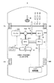
図1は、本発明の実施の形態による車両の代表例として示されるハイブリッド車両5の概略構成図である。
(Vehicle configuration)
FIG. 1 is a schematic configuration diagram of a
図1を参照して、ハイブリッド車両5は、エンジンENGと、モータジェネレータMG1,MG2と、バッテリ10と、電力変換ユニット(PCU:Power Control Unit)20と、動力分割機構PSDと、減速機RDと、前輪70L,70Rと、後輪80L,80Rと、電子制御ユニット(Electrical Control Unit:ECU)30とを備える。本実施の形態に係る制御装置は、たとえばECU30が実行するプログラムにより実現される。なお、図1には、前輪70L,70Rを駆動輪とするハイブリッド車両5が例示されるが、前輪70L,70Rに代えて後輪80L,80Rを駆動輪としてもよい。あるいは、図1に構成に加えて後輪80L,80R駆動用のモータジェネレータをさらに設けて、4WD構成とすることも可能である。
Referring to FIG. 1,
エンジンENGが発生する駆動力は、動力分割機構PSDにより、2経路に分割される。一方は、減速機RDを介して前輪70L,70Rを駆動する経路である。もう一方は、モータジェネレータMG1を駆動させて発電する経路である。
The driving force generated by the engine ENG is divided into two paths by the power split mechanism PSD. One is a path for driving the
モータジェネレータMG1は、代表的には三相交流同期電動発電機により構成される。モータジェネレータMG1は、動力分割機構PSDにより分割されたエンジンENGの駆動力により、発電機として発電する。また、モータジェネレータMG1は、発電機としての機能だけでなく、エンジンENGの回転数を制御するアクチュエータとしても機能をも有する。 Motor generator MG1 is typically constituted by a three-phase AC synchronous motor generator. Motor generator MG1 generates electricity as a generator by the driving force of engine ENG divided by power split mechanism PSD. Motor generator MG1 has not only a function as a generator but also a function as an actuator for controlling the rotational speed of engine ENG.
なお、モータジェネレータMG1により発電された電力は、車両の運転状態やバッテリ10のSOC(State Of Charge)の状態に応じて使い分けられる。たとえば、通常走行時や急加速時では、モータジェネレータMG1により発電された電力はそのままモータジェネレータMG2をモータとして駆動させる動力となる。一方、バッテリ10のSOCが予め定められた値よりも低い場合には、モータジェネレータMG1により発電された電力は、電力変換ユニット20により交流電力から直流電力に変換されてバッテリ10に蓄えられる。
The electric power generated by motor generator MG1 is selectively used according to the driving state of the vehicle and the state of charge (SOC) of
このモータジェネレータMG1は、エンジンENGを始動する際の始動機としても利用される。エンジンENGを始動する際、モータジェネレータMG1は、バッテリ10から電力の供給を受けて、電動機として駆動する。そして、モータジェネレータMG1は、エンジンENGをクランキングして始動する。
The motor generator MG1 is also used as a starter when starting the engine ENG. When starting engine ENG, motor generator MG1 is supplied with electric power from
モータジェネレータMG2は、代表的には三相交流同期電動発電機により構成される。モータジェネレータMG2が電動機として駆動される場合には、バッテリ10に蓄えられた電力およびモータジェネレータMG1により発電された電力の少なくともいずれか一方により駆動される。モータジェネレータMG2の駆動力は、減速機RDを介して前輪70L,70Rに伝えられる。これにより、モータジェネレータMG2は、エンジンENGをアシストして車両を走行させたり、モータジェネレータMG2の駆動力のみにより車両を走行させたりする。
Motor generator MG2 is typically constituted by a three-phase AC synchronous motor generator. When motor generator MG2 is driven as an electric motor, it is driven by at least one of electric power stored in
車両の回生制動時には、減速機RDを介して前輪70L,70RによりモータジェネレータMG2が駆動され、モータジェネレータMG2が発電機として作動させられる。これによりモータジェネレータMG2は、制動エネルギを電気エネルギに変換する回生ブレーキとして作用する。モータジェネレータMG2により発電された電力は、電力変換ユニット20を介してバッテリ10に蓄えられる。
During regenerative braking of the vehicle, the motor generator MG2 is driven by the
バッテリ10は、たとえば、ニッケル水素またはリチウムイオン等の二次電池により構成される。本発明の実施の形態において、バッテリ10は「蓄電装置」の代表例として示される。すなわち、電気二重層キャパシタ等の他の蓄電装置をバッテリ10に代えて用いることも可能である。バッテリ10は、直流電圧を電力変換ユニット20へ供給するとともに、電力変換ユニット20からの直流電圧によって充電される。
The
電力変換ユニット20は、バッテリ10よって供給される直流電力と、モータを駆動制御する交流電力およびジェネレータによって発電される交流電力との間で双方向の電力変換を行なう。
The
ハイブリッド車両5は、さらに、ハンドル40と、運転者によるアクセルペダルの踏み込み量に対応するアクセル開度Accを検出するアクセルポジションセンサ44と、ブレーキペダルポジションBPを検出するブレーキペダルポジションセンサ46と、シフトポジションSPを検出するシフトポジションセンサ48とを備える。
The
また、モータジェネレータMG1,MG2には、ロータ回転角を検出する回転角センサ51,52がさらに設けられる。回転角センサ51によって検出されたモータジェネレータMG1のロータ回転角θ1および回転角センサ52によって検出されたモータジェネレータMG2のロータ回転角θ2は、ECU30へ伝達される。なお、回転角センサ51,52は、ECU30においてモータジェネレータMG1の電流、電圧等からロータ回転角θ1を推定し、また、モータジェネレータMG2の電流、電圧等からロータ回転角θ2を推定することによって、配置を省略してもよい。
Motor generators MG1 and MG2 are further provided with
ハイブリッド車両5は、さらに、パワースイッチ90を備える。パワースイッチ90は、加速性を重視するパワーモードでの走行を運転者が選択するためのスイッチである。パワースイッチ90は、ECU30と電気的に接続されている。ECU30は、パワースイッチ90のオン/オフ状態を示すパワースイッチ信号Pswを受ける。このパワースイッチ信号Pswがオン状態であるときに、ECU30は、運転者によりパワーモードが選択されていると判断する。
The
ECU30は、エンジンENG、電力変換ユニット20およびバッテリ10と電気的に接続されている。ECU30は、各種センサからの検出信号およびパワースイッチ90からのパワースイッチ信号Pswに基づいて、ハイブリッド車両5が所望の走行状態となるように、エンジンENGの運転状態と、モータジェネレータMG1,MG2の駆動状態と、バッテリ10の充電状態とを統合的に制御する。
図2は、図1のハイブリッド車両5におけるパワートレインの詳細を説明するための模式図である。
FIG. 2 is a schematic diagram for explaining details of the power train in the
図2を参照して、ハイブリッド車両5のパワートレイン(ハイブリッドシステム)は、モータジェネレータMG2と、モータジェネレータMG2の出力軸160に接続される減速機RDと、エンジンENGと、モータジェネレータMG1と、動力分割機構PSDとを備える。
Referring to FIG. 2, the power train (hybrid system) of
動力分割機構PSDは、図2に示す例では遊星歯車機構により構成されて、クランクシャフト150に軸中心を貫通された中空のサンギヤ軸に結合されたサンギヤ151と、クランクシャフト150と同軸上を回転可能に支持されているリングギヤ152と、サンギヤ151とリングギヤ152との間に配置され、サンギヤ151の外周を自転しながら公転するピニオンギヤ153と、クランクシャフト150の端部に結合され各ピニオンギヤ153の回転軸を支持するプラネタリキャリヤ154とを含む。
In the example shown in FIG. 2, the power split mechanism PSD is constituted by a planetary gear mechanism, and a
動力分割機構PSDは、サンギヤ151に結合されたサンギヤ軸と、リングギヤ152に結合されたリングギヤケース155およびプラネタリキャリヤ154に結合されたクランクシャフト150の3軸が動力の入出力軸とされる。そしてこの3軸のうちいずれか2軸へ入出力される動力が決定されると、残りの1軸に入出力される動力は他の2軸へ入出力される動力に基づいて定まる。
In power split mechanism PSD, three axes of a sun gear shaft coupled to
動力の取出用のカウンタドライブギヤ170がリングギヤケース155の外側に設けられ、リングギヤ152と一体的に回転する。カウンタドライブギヤ170は、動力伝達減速ギヤRGに接続されている。リングギヤケース155は、本発明での「出力部材」に対応する。このようにして、動力分割機構PSDは、モータジェネレータMG1による電力および動力の入出力を伴って、エンジンENGからの出力の少なくとも一部を出力部材へ出力するように動作する。
A
さらに、カウンタドライブギヤ170と動力伝達減速ギヤRGとの間で動力の伝達がなされる。そして、動力伝達減速ギヤRGは、駆動輪である前輪70L、70Rと連結されたディファレンシャルギヤDEFを駆動する。また、下り坂等では駆動輪の回転がディファレンシャルギヤDEFに伝達され、動力伝達減速ギヤRGはディファレンシャルギヤDEFによって駆動される。
Further, power is transmitted between the
モータジェネレータMG1は、回転磁界を形成するステータ131と、ステータ131内部に配置され複数個の永久磁石が埋め込まれているロータ132とを含む。ステータ131は、ステータコア133と、ステータコア133に巻回される三相コイル134とを含む。ロータ132は、動力分割機構PSDのサンギヤ151と一体的に回転するサンギヤ軸に結合されている。ステータコア133は、電磁鋼板の薄板を積層して形成されており、図示しないケースに固定されている。
Motor generator MG1 includes a
モータジェネレータMG1は、ロータ132に埋め込まれた永久磁石による磁界と三相コイル134によって形成される磁界との相互作用によりロータ132を回転駆動する電動機として動作する。またモータジェネレータMG1は、永久磁石による磁界とロータ132の回転との相互作用により三相コイル134の両端に起電力を生じさせる発電機としても動作する。
Motor generator MG1 operates as an electric motor that rotationally drives
モータジェネレータMG2は、回転磁界を形成するステータ136と、ステータ136内部に配置され複数個の永久磁石が埋め込まれたロータ137とを含む。ステータ136は、ステータコア138と、ステータコア138に巻回される三相コイル139とを含む。
Motor generator MG2 includes a
ロータ137は、動力分割機構PSDのリングギヤ152と一体的に回転するリングギヤケース155に減速機RDを介して結合されている。ステータコア138は、たとえば電磁鋼板の薄板を積層して形成されており、図示しないケースに固定されている。
The
モータジェネレータMG2は、永久磁石による磁界とロータ137の回転との相互作用により三相コイル139の両端に起電力を生じさせる発電機としても動作する。またモータジェネレータMG2は、永久磁石による磁界と三相コイル139によって形成される磁界との相互作用によりロータ137を回転駆動する電動機として動作する。
Motor generator MG2 also operates as a generator that generates an electromotive force at both ends of three-
減速機RDは、プラネタリギヤの回転要素の一つであるプラネタリキャリヤ166がケースに固定された構造により減速を行なう。すなわち、減速機RDは、ロータ137の出力軸160に結合されたサンギヤ162と、リングギヤ152と一体的に回転するリングギヤ168と、リングギヤ168およびサンギヤ162に噛み合いサンギヤ162の回転をリングギヤ168に伝達するピニオンギヤ164とを含む。たとえば、サンギヤ162の歯数に対しリングギヤ168の歯数を2倍以上にすることにより、減速比を2倍以上にすることができる。
The speed reducer RD performs speed reduction by a structure in which a
このようにモータジェネレータMG2の回転力は、減速機RDを介して、リングギヤ152,168と一体的に回転する出力部材(リングギヤケース)155に伝達される。すなわち、モータジェネレータMG2は、出力部材155から駆動輪までの間で動力を加えるように構成される。なお、減速機RDの配置を省略して、すなわち減速比を設けることなく、モータジェネレータMG2の出力軸160および出力部材155の間を連結してもよい。
Thus, the rotational force of motor generator MG2 is transmitted to output member (ring gear case) 155 that rotates integrally with ring gears 152 and 168 via reduction gear RD. That is, motor generator MG2 is configured to apply power between
電力変換ユニット20は、コンバータ12と、インバータ14,22とを含む。コンバータ12は、バッテリ10からの直流電圧Vbを電圧変換して電源ラインPLおよび接地ラインGL間に直流電圧VHを出力する。また、コンバータ12は、双方向に電圧変換可能に構成されて、電源ラインPLおよび接地ラインGL間の直流電圧VHをバッテリ10の充電電圧Vbに変換する。
インバータ14,22は、一般的な三相インバータで構成されて、電源ラインPLおよび接地ラインGL間の直流電圧VHを交流電圧に変換してそれぞれモータジェネレータMG2,MG1へ出力する。また、インバータ14,22は、モータジェネレータMG2,MG1によって発電された交流電圧を直流電圧VHに変換して、電源ラインPLおよび接地ラインGL間に出力する。
上述のように構成されたハイブリッド車両5は、通常走行に対応するノーマルモードと、同一アクセル操作量に対する車両駆動力がノーマルモードよりも大きいパワーモードとを選択して走行可能に構成される。運転者は、パワースイッチ90を操作することにより、ノーマルモードおよびパワーモードのいずれかを選択できる。ECU30は、後述するように、選択された走行モードと、出力部材155に出力すべき要求トルクとを対応付けたテーブルを記憶している。このテーブルに記憶される要求トルクは、所定のアクセル開度に対して得られる駆動力が、ノーマルモードよりもパワーモードの方が高くなるように設定されている。ECU30は、各走行モードにおいて、このテーブルを参照してアクセル開度Accに基づいて出力部材155に出力すべき要求トルクを算出する。そして、この要求トルクに対応する要求駆動力が出力部材155に出力されるように、エンジンENGの運転状態と、モータジェネレータMG1,MG2の駆動状態とを制御する。
The
(制御構造)
次に、図3を参照して、本実施の形態による車両の走行モードの切換え動作を実現するための制御構造について、図面を参照して説明する。
(Control structure)
Next, referring to FIG. 3, a control structure for realizing the operation of switching the travel mode of the vehicle according to the present embodiment will be described with reference to the drawings.
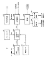
図3は、本実施の形態に従うECU30における制御構造を示すブロック図である。図3に示す各機能ブロックは、代表的にECU30が予め格納されたプログラムを実行することで実現されるが、その機能の一部または全部を専用のハードウェアとして実装してもよい。
FIG. 3 is a block diagram showing a control structure in
図3を参照して、ECU30は、MG2ロック検出部300と、走行モード選択部310と、充放電制御部320と、走行制御部330と、配分部340と、インバータ制御部350と、コンバータ制御部360とを備える。
Referring to FIG. 3,
MG2ロック検出部300は、モータジェネレータMG2の回転数センサ51によって検出された、または推定されたロータ回転角θ2に基づいてMG2回転数Nm2を検出する。そして、MG2ロック検出部300は、検出されたMG2回転数Nm2およびモータジェネレータMG2の電流に基づいて、モータジェネレータMG2にロック状態が発生しているかどうかを検出する。ロック状態の発生時には、MG2ロック検出部300は、ロック判定フラグFLCをオンに設定する。
MG2
MG2ロック検出部300によるロック検出は、MG2回転数Nm2が、回転数=0を含む極低回転数領域(N2n≦Nm2≦N2p)に入っているかどうか、および、モータジェネレータMG2の電流が所定のロック判定値M2以上であるかどうかにより判定される。なお、N2pは回転数が正転領域のロック判定値であり、N2nは回転数が逆転領域のロック判定値である。また、M2は、ロック状態が発生するとモータジェネレータMG2の特定の相に電流が継続的に流れることを考慮して、モータジェネレータMG2の三相電流よりも高い電流値となるように設定される。
The lock detection by the MG2
なお、ロック検出は、MG2回転数およびモータジェネレータMG2のトルク指令値に基づいて行なう構成としてもよい。この場合、モータジェネレータMG1にトルク指令値が与えられているにもかかわらず、MG2回転数が上昇しないときには、モータジェネレータMG2にロック状態が発生していると判定することができる。 Lock detection may be performed based on the MG2 rotation speed and the torque command value of motor generator MG2. In this case, it can be determined that the motor generator MG2 is locked when the MG2 rotation speed does not increase despite the torque command value being given to the motor generator MG1.
走行モード選択部310は、MG2ロック検出部300からロック判定フラグFLCを受け、パワースイッチ90からパワースイッチ信号Pswを受け、車速センサ100から車速Vを受ける。そして、走行モード選択部310は、これらの入力信号に基づいて、ノーマルモードおよびパワーモードの一方を選択する。走行モード選択部310は、ノーマルモードおよびパワーモードのいずれが選択されているかを示す走行モードフラグFMを発生する。走行モードフラグFMは、走行制御部330へ送出される。
Traveling
充放電制御部320は、バッテリ10のSOCに基づいて、充電電力上限値Winおよび放電電力上限値Woutを設定する。なお、図示は省略するが、バッテリ10のSOCは、バッテリ10に設けられた電池監視ユニットからの電池データ(バッテリ10の電流、電圧および温度)に基づいて算出されたSOC推定値である。
Charging / discharging
走行制御部330は、ハイブリッド車両5の走行モード、車両状態およびドライバ操作に応じて、ハイブリッド車両5全体で必要な車両駆動力や車両制動力を算出する。車両状態には、車速Vが含まれる。また、ドライバ操作には、アクセル開度Acc、ブレーキペダルポジションBP、シフトポジションSP等が含まれる。
The traveling
そして、走行制御部330は、要求された車両駆動力あるいは車両制動力を実現するように、モータジェネレータMG1,MG2への出力要求およびエンジンENGへの出力要求を決定する。ハイブリッド車両5は、エンジンENGを停止したままでモータジェネレータMG2の出力のみで走行することができる。したがって、燃費が悪い領域を避けてエンジンENGを動作させるように、各出力要求を決定することによって、エネルギ効率を高めることができる。さらに、モータジェネレータMG1,MG2への出力要求は、バッテリ10の充放電可能な電力範囲内(Win〜Wout)でバッテリ10の充放電が実行されるように制限した上で設定される。すなわち、バッテリ10の出力電力が確保できないときには、モータジェネレータMG2による出力が制限される。
配分部340は、走行制御部330によって設定されたモータジェネレータMG1,MG2への出力要求に応じて、モータジェネレータMG1,MG2のトルクや回転速度を演算する。そしてトルクや回転速度についての制御指令をインバータ制御部350へ出力すると同時に、電圧VHの制御指令値をコンバータ制御部360へ出力する。
一方、配分部340は、走行制御部330によって決定されたエンジンパワーおよびエンジン目標回転速度を示すエンジン制御指示を生成する。このエンジン制御指示に従って、図示しないエンジンENGの燃料噴射、点火時期、バルブタイミング等が制御される。
On the other hand, the
インバータ制御部350は、配分部340からの制御指令に応じて、コンバータ12の出力である直流電圧を、モータジェネレータMG1を駆動するための交流電圧に変換する駆動指示を行なう制御信号と、モータジェネレータMG1で発電された交流電圧を直流電圧に変換してコンバータ12側に戻す回生指示を行なう制御信号とを生成する。これらのモータジェネレータMG1の制御指令(MG1制御指令)は、インバータ22へ出力される。同様にインバータ制御部350は、モータジェネレータMG2を駆動するための交流電圧に直流電圧を変換する駆動指示を行なう制御信号と、モータジェネレータMG2で発電された交流電圧を直流電圧に変換してコンバータ12側に戻す回生指示を行なう制御信号とを出力する。これらのモータジェネレータMG2の制御指令(MG2制御指令)は、インバータ14へ出力される。
コンバータ制御部360は、配分部340からの制御指令に従って直流電圧VHが制御されるように、コンバータ12に対して昇圧指示を行なう制御信号、降圧指示を行なう制御信号および動作禁止を指示するシャットダウン信号を生成する。これらの制御信号に従ったコンバータ12の電圧変換によって、バッテリ10の充放電電力が制御されることになる。
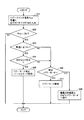
次に、ECU30の動作、特にパワーモードが選択される際の動作について図面を用いて説明する。図4は、ECU30における走行モード切換え動作を示すフローチャートである。このフローチャートの処理は、ハイブリッド車両5が走行可能な状態にあるとき、一定時間ごとまたは所定の条件が成立するごとに実行される。
Next, the operation of the
図4を参照して、まず、走行モード選択部310として機能するECU30は、パワースイッチ90からのパワースイッチ信号Psw、車速センサ100からの車速Vおよび現在の走行モードを示す走行モードフラグFMなどの走行制御に必要なデータを受付ける処理を実行する(ステップS01)。
Referring to FIG. 4, first,
次に、走行モード選択部310は、入力されたパワースイッチ信号Pswがオン状態であるか否か、すなわち、運転者によりパワーモードが選択されているか否かを判定する(ステップS02)。パワースイッチ信号Pswがオン状態でないとき、すなわち、運転者によりパワーモードが選択されていないとき(ステップS02においてNOの場合)には、走行モード切換え動作に係る処理は終了する。この場合、走行モード選択部310は、走行モードを、現状の走行モード、すなわちノーマルモードに設定する。
Next, the traveling
これに対して、パワースイッチ信号Pswがオン状態であるとき、すなわち、運転者によりパワーモードが選択されているとき(ステップS02においてYESの場合)には、走行モード選択部310は、車速センサ100からの車速VおよびMG2ロック検出部300からのロック判定フラグFLCに基づいて、ハイブリッド車両5の車輪にロック状態が発生しているか否かを判定する。
On the other hand, when the power switch signal Psw is in the on state, that is, when the power mode is selected by the driver (in the case of YES in step S02), the traveling
具体的には、ECU30は、まず、車速センサ100からの車速Vが所定の閾値Vth以下であるか否かを判定する(ステップS03)。この閾値Vthは、ハイブリッド車両5が段差や登坂路などにおいてロック状態となっている場合を想定して、車速=0を含む極低速域の範囲内に設定される。車速Vが閾値Vth以下であるとき(ステップS03においてYESの場合)には、走行モード選択部310は次いで、ロック判定フラグFLCに基づいて、モータジェネレータMG2にロック状態が発生しているか否かを判定する(ステップS04)。本実施の形態に係るハイブリッド車両5では、図2で示したように、モータジェネレータMG2は、出力部材155と機械的に結合されており、出力部材155から駆動輪までの間で動力を加えるように構成される。したがって、モータジェネレータMG2にロック状態が発生しているか否かを検出することにより、車輪にロック状態が発生しているか否かを判定することができる。
Specifically, the
ロック判定フラグFLCがオンに設定されているとき、すなわち、モータジェネレータMG2にロック状態が発生しているとき(ステップS04においてYESの場合)には、走行モード選択部310は、パワーモードの選択が禁止される(ステップS05)。これにより、パワースイッチ90がオンされているにもかかわらず、走行モードとしてノーマルモードが維持される。
When lock determination flag FLC is set on, that is, when a locked state is generated in motor generator MG2 (in the case of YES in step S04), traveling
すなわち、ECU30が図4のステップS02〜S05に示す処理を実行することにより、運転者によりパワーモードが選択されている場合であっても、車輪にロック状態が発生しているときには、ノーマルモードからパワーモードへの走行モードの切換えが禁止されることとなる。これにより、車輪にロック状態が発生しており、車輪をロック状態から脱出させるために運転者による細かなアクセル操作量の調整が必要とされる場面において、運転者の意図しない駆動力が発生するのを抑制することができる。
That is, when the
これに対して、運転者によりパワーモードが選択されている場合(ステップS02においてYESの場合)であって、車速センサ100からの車速Vが閾値Vthを超えるとき(ステップS03においてNOの場合)には、走行モード選択部310は、走行モードフラグFMに基づいて、前回このルーチンで設定した走行モードがパワーモードであるか否かを判定する(ステップS06)。前回の走行モードがパワーモードであると判定されると(ステップS06においてYESの場合)、走行モード選択部310は、走行モードとしてパワーモードを維持して、走行モード切換え動作に係る処理は終了する(ステップS07)。
On the other hand, when the power mode is selected by the driver (YES in step S02) and when vehicle speed V from
また、運転者によりパワーモードが選択されている場合(ステップS02においてYESの場合)であって、車速センサ100からの車速Vが閾値Vth以下(ステップS03においてYESの場合)であり、かつ、モータジェネレータMG2にロック状態が発生していないとき(ステップS04においてNOの場合)においても、走行モード選択部310は、走行モードフラグFMに基づいて、前回このルーチンで設定した走行モードがパワーモードであるか否かを判定する(ステップS06)。前回の走行モードがパワーモードであると判定されると(ステップS06においてYESの場合)、走行モード選択部310は、走行モードとしてパワーモードを維持して、走行モード切換え動作に係る処理は終了する(ステップS07)。
Further, when the power mode is selected by the driver (YES in step S02), vehicle speed V from
これに対して、ステップS06において前回このルーチンで設定した走行モードがノーマルモードであると判定された場合(ステップS06においてNOの場合)には、走行モード選択部310は、パワーモードの選択が許可される。したがって、走行モード選択部310は、パワーモードが選択されたことを示す走行モードフラグFMを走行制御部330へ送出する。走行制御部330は、走行モード選択部310からの走行モードフラグFMに従って、ハイブリッド車両5の走行モードをノーマルモードからパワーモードに切換える(ステップS08)。
On the other hand, when it is determined in step S06 that the travel mode previously set in this routine is the normal mode (NO in step S06), travel
走行モードをノーマルモードからパワーモードに切換えるに際して、走行制御部330は、ノーマルモード時にアクセルポジションセンサ44からのアクセル開度Accに基づいて設定される車両駆動力から、パワーモード時にアクセルポジションセンサ44からのアクセル開度Accに基づいて設定される車両駆動力までの間で、車両駆動力を徐々に増大させる。このように車両駆動力に緩変化処理を施すのは、ノーマルモードからパワーモードに移行した直後においてアクセル操作量に対する車両駆動力がいきなり増大することによって、運転者に対して車両の飛び出し感を与えるおそれがあるためである。
When switching the travel mode from the normal mode to the power mode, the
図5は、図4のステップS08(走行モード切換え処理)のサブルーチンを説明するフローチャートである。 FIG. 5 is a flowchart illustrating a subroutine of step S08 (travel mode switching process) in FIG.
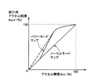
図5を参照して、まず、走行制御部330は、フラグF2に値0を設定し(ステップS11)、パワーモードマップを用いて仮実行用アクセル開度Accpowを設定する(ステップS12)。フラグF2は、パワーモード用に実行用アクセル開度Acc*を設定する処理が実行されたときに値0が設定される。このステップS12においては、走行制御部330は、図6に示すアクセル開度Accと仮実行用アクセル開度Accpowとの関係を予めマップとして記憶しておき、アクセルポジションセンサ44からアクセル開度Accが与えられると、当該マップを参照して、対応する仮実行用アクセル開度Accpowを設定する。
Referring to FIG. 5, first, traveling
図6に、パワーモードマップの一例を示す。同図では、後述するノーマルモードマップも併せて示す。図6を参照して、ノーマルモードマップでは、0〜100%の範囲でアクセル開度Accに対して仮実行用アクセル開度Accnorが線形性を持つように定められている。これに対して、パワーモードマップでは、所定開度Acc0以下の低アクセル開度領域にあるアクセル開度Accに対してはノーマルモードマップにより設定される仮実行用アクセル開度Accnorと値が同一の仮実行用アクセル開度Accpowとなる線形性を持つとともに、所定開度Acc0よりも大きいアクセル開度Accに対しては仮実行用アクセル開度Accnorよりも大きな値の仮実行用アクセル開度Accpowとなる非線形性を持つように定められている。これは、停車時にアクセルペダルを全閉としてクリープ走行する際に、アクセルペダルの全閉位置にずれが生じていたりすると、運転者はアクセルペダルを踏み込んでいなくても若干の開判定がなされる場合があるが、このときに0〜100%の全ての開度領域に亘ってノーマルモードマップよりも大きな実行用アクセル開度Acc*が設定されるようにパワーモードマップを定めると(図6の破線参照)、大きな実行用アクセル開度Acc*が設定されて車両の飛び出し感を与える場合があるからである。 FIG. 6 shows an example of the power mode map. In the figure, a normal mode map described later is also shown. Referring to FIG. 6, in the normal mode map, provisional execution accelerator opening Accnor is determined to have linearity with respect to accelerator opening Acc in a range of 0 to 100%. On the other hand, in the power mode map, the accelerator opening Acc in the low accelerator opening region of the predetermined opening Acc0 or less has the same value as the temporary execution accelerator opening Accnor set by the normal mode map. The temporary opening accelerator opening Accpow has a linearity that is the temporary opening accelerator opening Accpow, and is larger than the temporary execution accelerator opening Accnor for an accelerator opening Acc larger than the predetermined opening Acc0. It is determined to have non-linearity. This is because, when creeping with the accelerator pedal fully closed when the vehicle is stopped, a slight open determination is made even if the driver does not depress the accelerator pedal if there is a shift in the fully closed position of the accelerator pedal. In this case, if the power mode map is determined so that the execution accelerator opening Acc * larger than the normal mode map is set over the entire opening range of 0 to 100% at this time (FIG. 6). This is because a large execution accelerator opening Acc * may be set to give the vehicle a feeling of popping out.
次に、走行制御部330は、フラグF1の値を調べる(ステップS13)。このフラグF1は、ノーマルモード用に実行用アクセル開度Acc*を設定する処理が実行されたときに値0が設定される。いま、ノーマルモードからパワーモードに切換えられた直後を考えると、フラグF1が値0と判定される(ステップS13においてYESの場合)。
Next, the traveling
走行制御部330は、図6のノーマルモードマップを参照して、アクセルポジションセンサ44からのアクセル開度Accに基づいて仮実行用アクセル開度Accnorを設定する(ステップS14)。そして、走行制御部330は、ステップS12で設定した仮実行用アクセル開度Accpowから仮実行用アクセル開度Accnorを減じることにより、開度差ΔAを計算する(ステップS15)。次に、走行制御部330は、前回このルーチンで設定された開度補正量Aset1に所定量A1を加えることにより新たな開度補正量Aset1を設定し(ステップS16)、開度補正量Aset1と開度差ΔAとを比較する(ステップS17)。
The
開度補正量Aset1が開度差ΔA未満と判定されると(ステップS17においてNOの場合)、走行制御部330は、ステップS14で設定した仮実行用アクセル開度Accnorに開度補正量Aset1を加えたものと実行用アクセル開度Acc*に設定して(ステップS21)、処理を終了する。
When it is determined that the opening correction amount Aset1 is less than the opening difference ΔA (NO in step S17), the traveling
これに対して、開度補正量Aset1が開度差ΔA以上と判定されると(ステップS17においてYESの場合)、走行制御部330は、フラグF1に値1を設定するとともに(ステップS18)、開度補正量Aset1に値0を設定する(ステップS19)。さらに、走行制御部330は、ステップS12で設定した仮実行用アクセル開度Accpowを実行用アクセル開度Acc*に設定して(ステップS20)、処理を終了する。
On the other hand, when it is determined that the opening correction amount Aset1 is equal to or larger than the opening difference ΔA (in the case of YES in step S17), the traveling
なお、フラグF1に値1が設定された以降は、ステップS13で否定的な判定がなされるから、仮実行用アクセル開度Accpowを実行用アクセル開度Acc*に設定するステップS20の処理が繰返されることになる。
Since the negative determination is made in step S13 after the
このように、ノーマルモードからパワーモードに切換えられたときには、実行用アクセル開度Acc*を、レート処理を用いて仮実行用アクセル開度Accnorから仮実行用アクセル開度Accpowまで徐々に変化させることにより、ノーマルモードからパワーモードへの切換えをスムーズに行なうことができる。したがって、車輪がロック状態から脱出したことによってパワーモードの選択が許可されることにより、走行モードがノーマルモードからパワーモードに切換えられるところ(図4のステップS08)、パワーモードへの切換え直後において、大きな実行用アクセル開度Acc*が設定されて車両駆動力がいきなり増大し、運転者に飛び出し感を与えるのを抑制することができる。なお、ステップS16に示す所定量A1は、レート処理に用いられるレート値であり、ハイブリッド車両5の仕様に基づいて定められる。
Thus, when the normal mode is switched to the power mode, the execution accelerator opening Acc * is gradually changed from the temporary execution accelerator opening Accnor to the temporary execution accelerator opening Accpow using the rate processing. Thus, switching from the normal mode to the power mode can be performed smoothly. Therefore, when the selection of the power mode is permitted when the wheel has escaped from the locked state, the travel mode is switched from the normal mode to the power mode (step S08 in FIG. 4), immediately after the switch to the power mode, A large execution accelerator opening Acc * is set, so that the vehicle driving force suddenly increases, and it is possible to suppress giving the driver a feeling of popping out. The predetermined amount A1 shown in step S16 is a rate value used for rate processing, and is determined based on the specifications of the
なお、図5のフローチャートに従って実行用アクセル開度Acc*を設定すると、走行制御部330は、設定した実行用アクセル開度Acc*および車速Vに基づいて、ハイブリッド車両5に要求されるトルクとして、出力部材155に出力すべき要求トルクTr*とエンジンENGに要求されるパワーPe*とを設定する。
When the execution accelerator opening Acc * is set according to the flowchart of FIG. 5, the traveling
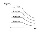
要求トルクTr*については、本実施例では、実行用アクセル開度Acc*と車速Vと要求トルクTr*との関係を予め要求トルク設定用マップとして記憶しておき、実行用アクセル開度Acc*および車速Vが与えられると、要求トルク設定用マップを参照して、対応する要求トルクTr*を導出するものとする。図7に、要求トルク設定用マップの一例を示す。 Regarding the required torque Tr *, in this embodiment, the relationship between the execution accelerator opening Acc *, the vehicle speed V, and the required torque Tr * is stored in advance as a required torque setting map, and the execution accelerator opening Acc * is stored. When the vehicle speed V is given, the corresponding required torque Tr * is derived with reference to the required torque setting map. FIG. 7 shows an example of the required torque setting map.
走行制御部330は、設定した要求トルクTr*および要求パワーPe*に基づいて、モータジェネレータMG1,MG2への出力要求およびエンジンENGへの出力要求を決定する。なお、モータジェネレータMG1,MG2への出力要求は、バッテリ10の充放電可能な電力範囲内(Win〜Wout)でバッテリ10の充放電が実行されるように制限した上で設定される。すなわち、バッテリ10の出力電力が確保できないときには、モータジェネレータMG2による出力が制限される。
配分部340は、走行制御部330によって設定されたモータジェネレータMG1,MG2への出力要求に応じて、モータジェネレータMG1,MG2のトルクや回転速度を演算する。そしてトルクや回転速度についての制御指令をインバータ制御部350へ出力すると同時に、電圧VHの制御指令値をコンバータ制御部360へ出力する。
一方、配分部340は、走行制御部330によって決定されたエンジンパワーおよびエンジン目標回転速度を示すエンジン制御指示を生成する。このエンジン制御指示に従って、図示しないエンジンENGの燃料噴射、点火時期、バルブタイミング等が制御される。
On the other hand, the
なお、この発明の実施の形態と本願発明との対応関係については、ノーマルモードが「第1の走行モード」に相当し、パワーモードが「第2の走行モード」に相当する。また、ECU30は、「検知手段」、「切換え手段」、「ロック検出手段」、「禁止手段」および「ロック脱出検出手段」を構成する。
As for the correspondence between the embodiment of the present invention and the present invention, the normal mode corresponds to the “first travel mode” and the power mode corresponds to the “second travel mode”. The
以上説明したように、この発明の実施の形態による車両においては、運転者によりパワーモードが選択されている場合であっても、車輪にロック状態が発生していることが検出されたときには、パワーモードへの切換えが禁止される。これにより、車輪をロック状態から脱出させるために運転者による細かなアクセル操作が必要とされる場面において、運転者の意図しない駆動力が出力されるのを抑制することができる。 As described above, in the vehicle according to the embodiment of the present invention, when it is detected that the wheel is locked even when the power mode is selected by the driver, the power is Switching to the mode is prohibited. Thereby, in a scene where a fine accelerator operation by the driver is required to escape the wheel from the locked state, it is possible to suppress the output of the driving force not intended by the driver.
また、車輪をロック状態から脱出したことによってパワーモードヘの切換えが許可されたときには、車両駆動力を、ノーマルモード時にアクセル開度に基づいて設定される車両駆動力からパワーモード時にアクセル開度に基づいて設定される車両駆動力まで緩変化させることにより、パワーモードへの切換え直後に運転者に与えうる飛び出し感を抑制することができる。 In addition, when switching to the power mode is permitted by removing the wheel from the locked state, the vehicle driving force is changed from the vehicle driving force set based on the accelerator opening in the normal mode to the accelerator opening in the power mode. By slowly changing the vehicle driving force set based on this, it is possible to suppress the feeling of popping out that can be given to the driver immediately after switching to the power mode.
なお、上述した実施の形態においては、車両の代表例として、ハイブリッド車両について例示したが、本願発明は、通常走行に対応するノーマルモードと、同一アクセル操作量に対する車両駆動力がノーマルモードよりも大きいパワーモードとのいずれかを運転者により選択可能に構成された車両に適用することが可能である。たとえば、エンジンのみを駆動源とする通常の車両、電気自動車、燃料電池自動車等についても本願発明は適用可能である。また、ハイブリッド車両に適用する場合には、図1の構成とは異なる構成のハイブリッド構成のハイブリッド車両(たとえば、いわゆるシリーズハイブリッド構成や、電気分配式のハイブリッド構成)であってもよい。 In the above-described embodiment, a hybrid vehicle is illustrated as a representative example of the vehicle. However, the present invention has a normal mode corresponding to normal traveling and a vehicle driving force with respect to the same accelerator operation amount larger than that in the normal mode. Any one of the power modes can be applied to a vehicle configured to be selectable by the driver. For example, the present invention can also be applied to ordinary vehicles, electric vehicles, fuel cell vehicles, and the like that use only the engine as a drive source. Further, when applied to a hybrid vehicle, a hybrid vehicle having a hybrid configuration different from the configuration of FIG. 1 (for example, a so-called series hybrid configuration or an electric distribution type hybrid configuration) may be used.
また、上述した実施の形態においては、走行モードとしてパワーモードを選択することによって、通常走行よりも高い駆動力を発生させる構成について例示したが、本願発明は、一走行モードとしてパワーモードを備える車両に限定されるものではなく、加速性が要求される場面に応じて車両駆動力を通常走行時よりも増大させる機能を備えた車両に適用することが可能である。 In the above-described embodiment, the power mode is selected as the travel mode to generate a driving force higher than that of the normal travel. However, the present invention is a vehicle having the power mode as one travel mode. The present invention is not limited to this, and can be applied to a vehicle having a function of increasing the vehicle driving force more than that during normal traveling in accordance with a scene where acceleration is required.
今回開示された実施の形態はすべての点で例示であって制限的なものではないと考えられるべきである。本発明の範囲は、上記した実施の形態の説明ではなくて特許請求の範囲によって示され、特許請求の範囲と均等の意味および範囲内でのすべての変更が含まれることが意図される。 The embodiment disclosed this time should be considered as illustrative in all points and not restrictive. The scope of the present invention is shown not by the above description of the embodiments but by the scope of claims for patent, and is intended to include meanings equivalent to the scope of claims for patent and all modifications within the scope.
5 ハイブリッド車両、10 バッテリ、12 コンバータ、14,22 インバータ、20 電力変換ユニット、40 ハンドル、44 アクセルポジションセンサ、46 ブレーキペダルポジションセンサ、48 シフトポジションセンサ、51,52 回転角センサ、70L,70R 前輪、80L,80R 後輪、90 パワースイッチ、100 車速センサ、131,136 ステータ、132,137 ロータ、133,138 ステータコア、134,139 三相コイル、150 クランクシャフト、151,162 サンギヤ、152,168 リングギヤ、153,164 ピニオンギヤ、154,166 プラネタリキャリヤ、155 出力部材、160 出力軸、170 カウンタドライブギヤ、300 ロック検出部、310 走行モード選択部、320 充放電制御部、330 走行制御部、340 配分部、350 インバータ制御部、360 コンバータ制御部、DEF ディファレンシャルギヤ、ENG エンジン、MG1,MG2 モータジェネレータ、RD 減速機、RG 動力伝達減速ギヤ。 5 Hybrid vehicle, 10 Battery, 12 Converter, 14, 22 Inverter, 20 Power conversion unit, 40 Handle, 44 Accelerator position sensor, 46 Brake pedal position sensor, 48 Shift position sensor, 51, 52 Rotation angle sensor, 70L, 70R Front wheel , 80L, 80R Rear wheel, 90 Power switch, 100 Vehicle speed sensor, 131, 136 Stator, 132, 137 Rotor, 133, 138 Stator core, 134, 139 Three-phase coil, 150 Crankshaft, 151, 162 Sun gear, 152, 168 Ring gear , 153, 164 Pinion gear, 154, 166 Planetary carrier, 155 Output member, 160 Output shaft, 170 Counter drive gear, 300 Lock detector, 310 Travel Mode selection unit, 320 charge / discharge control unit, 330 travel control unit, 340 distribution unit, 350 inverter control unit, 360 converter control unit, DEF differential gear, ENG engine, MG1, MG2 motor generator, RD reducer, RG power transmission Reduction gear.
Claims (4)
運転者からの前記第2の走行モードへの切換え要求を検知するための検知手段と、
前記切換え要求が検知された場合に、前記第1の走行モード時と比較して車両駆動力を増大させることにより、前記車両を前記第2の走行モードへ切換えるための切換え手段と、
前記切換え要求が検知された場合に、車輪のロック状態を検出するためのロック検出手段と、
前記車輪のロック状態が検出されたときには、前記切換え手段による前記第2の走行モードへの切換えを禁止するための禁止手段とを備える、車両。 A vehicle having a first travel mode and a second travel mode in which the vehicle driving force for the same accelerator operation amount is greater than the first travel mode,
Detecting means for detecting a request for switching to the second traveling mode from the driver;
A switching means for switching the vehicle to the second traveling mode by increasing a vehicle driving force when the switching request is detected, compared to the first traveling mode;
Lock detecting means for detecting a locked state of the wheel when the switching request is detected;
A vehicle comprising: prohibiting means for prohibiting switching to the second travel mode by the switching means when the locked state of the wheels is detected.
前記運転者のアクセル操作量を検出するためのアクセル操作検出手段とをさらに備え、
前記禁止手段は、前記車輪がロック状態から脱出したことが検出されたときには、前記切換え手段による前記第2の走行モードへの切換えを許可し、
前記切換え手段は、前記禁止手段により前記第2の走行モードへの切換えが許可されたときには、前記第1の走行モード時に前記検出されたアクセル操作量に基づいて設定される第1の車両駆動力から、前記第2の走行モード時に前記検出されたアクセル操作量に基づいて設定される第2の車両駆動力までの間で、車両駆動力を徐々に増大させる、請求項1に記載の車両。 Lock escape detecting means for detecting that the wheel has escaped from the locked state during a period in which switching to the second traveling mode is prohibited by the prohibiting means;
An accelerator operation detecting means for detecting the driver's accelerator operation amount;
The prohibiting means permits the switching to the second traveling mode by the switching means when it is detected that the wheel has escaped from the locked state,
The switching means has a first vehicle driving force that is set based on the detected accelerator operation amount in the first traveling mode when the prohibiting means permits switching to the second traveling mode. 2. The vehicle according to claim 1, wherein the vehicle driving force is gradually increased between the first vehicle driving force and the second vehicle driving force set based on the detected accelerator operation amount in the second travel mode.
前記ロック検出手段は、車速が所定の閾値以下であって、かつ、前記電動機がロック状態であるときに、前記車輪のロック状態を検出する、請求項1または2に記載の車両。 An electric motor mechanically coupled to a drive shaft for driving the wheel;
The vehicle according to claim 1 or 2, wherein the lock detecting means detects the locked state of the wheel when the vehicle speed is equal to or lower than a predetermined threshold value and the electric motor is in a locked state.
運転者からの前記第2の走行モードへの切換え要求を検知するためのステップと、
前記検知するステップにより前記切換え要求が検知された場合に、前記第1の走行モード時と比較して車両駆動力を増大させることにより、前記車両を前記第2の走行モードへ切換えるためのステップと、
前記検知するステップにより前記切換え要求が検知された場合に、車輪のロック状態を検出するためのステップと、
前記検出するステップにより前記車輪のロック状態が検出されたときには、前記切換えるステップによる前記第2の走行モードへの切換えを禁止するためのステップとを備える、車両の制御方法。 A vehicle control method comprising: a first travel mode; and a second travel mode in which a vehicle driving force with respect to the same accelerator operation amount is greater than the first travel mode,
Detecting a request for switching to the second driving mode from the driver;
A step for switching the vehicle to the second traveling mode by increasing a vehicle driving force when compared with the first traveling mode when the switching request is detected by the detecting step; ,
A step for detecting a locked state of a wheel when the switching request is detected by the detecting step;
And a step of prohibiting switching to the second travel mode by the switching step when the wheel lock state is detected by the detecting step.
Priority Applications (1)
| Application Number | Priority Date | Filing Date | Title |
|---|---|---|---|
| JP2011004832A JP5598339B2 (en) | 2011-01-13 | 2011-01-13 | Vehicle and control method thereof |
Applications Claiming Priority (1)
| Application Number | Priority Date | Filing Date | Title |
|---|---|---|---|
| JP2011004832A JP5598339B2 (en) | 2011-01-13 | 2011-01-13 | Vehicle and control method thereof |
Publications (2)
| Publication Number | Publication Date |
|---|---|
| JP2012144175A true JP2012144175A (en) | 2012-08-02 |
| JP5598339B2 JP5598339B2 (en) | 2014-10-01 |
Family
ID=46788216
Family Applications (1)
| Application Number | Title | Priority Date | Filing Date |
|---|---|---|---|
| JP2011004832A Active JP5598339B2 (en) | 2011-01-13 | 2011-01-13 | Vehicle and control method thereof |
Country Status (1)
| Country | Link |
|---|---|
| JP (1) | JP5598339B2 (en) |
Citations (11)
| Publication number | Priority date | Publication date | Assignee | Title |
|---|---|---|---|---|
| JPH05178127A (en) * | 1991-11-29 | 1993-07-20 | Inoue Jidosha Kk | Preventing device for quick start of automatic transmission automobile |
| JPH0872589A (en) * | 1994-09-02 | 1996-03-19 | Hitachi Ltd | Powertrain control device and control method |
| JP2005117718A (en) * | 2003-10-03 | 2005-04-28 | Nissan Motor Co Ltd | Torque control device and torque control method for motor-driven vehicle |
| JP2005185065A (en) * | 2003-12-22 | 2005-07-07 | Nissan Motor Co Ltd | Vehicle driving force control device |
| JP2007069625A (en) * | 2005-09-02 | 2007-03-22 | Toyota Motor Corp | Hybrid vehicle and control method thereof |
| JP2007091073A (en) * | 2005-09-29 | 2007-04-12 | Toyota Motor Corp | Drive device, automobile equipped with the same, and drive device control method |
| JP2008126766A (en) * | 2006-11-17 | 2008-06-05 | Fuji Heavy Ind Ltd | Vehicle motion control device |
| JP2010011545A (en) * | 2008-06-24 | 2010-01-14 | Toyota Motor Corp | Controller of vehicle driving motor |
| JP2010144667A (en) * | 2008-12-19 | 2010-07-01 | Kenwood Corp | Safe driving device of vehicle |
| JP2011122607A (en) * | 2009-12-08 | 2011-06-23 | Denso Corp | Control device for vehicle |
| JP2011229326A (en) * | 2010-04-22 | 2011-11-10 | Nissan Motor Co Ltd | Control device of an electric motor in electric vehicle |
-
2011
- 2011-01-13 JP JP2011004832A patent/JP5598339B2/en active Active
Patent Citations (11)
| Publication number | Priority date | Publication date | Assignee | Title |
|---|---|---|---|---|
| JPH05178127A (en) * | 1991-11-29 | 1993-07-20 | Inoue Jidosha Kk | Preventing device for quick start of automatic transmission automobile |
| JPH0872589A (en) * | 1994-09-02 | 1996-03-19 | Hitachi Ltd | Powertrain control device and control method |
| JP2005117718A (en) * | 2003-10-03 | 2005-04-28 | Nissan Motor Co Ltd | Torque control device and torque control method for motor-driven vehicle |
| JP2005185065A (en) * | 2003-12-22 | 2005-07-07 | Nissan Motor Co Ltd | Vehicle driving force control device |
| JP2007069625A (en) * | 2005-09-02 | 2007-03-22 | Toyota Motor Corp | Hybrid vehicle and control method thereof |
| JP2007091073A (en) * | 2005-09-29 | 2007-04-12 | Toyota Motor Corp | Drive device, automobile equipped with the same, and drive device control method |
| JP2008126766A (en) * | 2006-11-17 | 2008-06-05 | Fuji Heavy Ind Ltd | Vehicle motion control device |
| JP2010011545A (en) * | 2008-06-24 | 2010-01-14 | Toyota Motor Corp | Controller of vehicle driving motor |
| JP2010144667A (en) * | 2008-12-19 | 2010-07-01 | Kenwood Corp | Safe driving device of vehicle |
| JP2011122607A (en) * | 2009-12-08 | 2011-06-23 | Denso Corp | Control device for vehicle |
| JP2011229326A (en) * | 2010-04-22 | 2011-11-10 | Nissan Motor Co Ltd | Control device of an electric motor in electric vehicle |
Also Published As
| Publication number | Publication date |
|---|---|
| JP5598339B2 (en) | 2014-10-01 |
Similar Documents
| Publication | Publication Date | Title |
|---|---|---|
| US8718854B2 (en) | Electrically-powered vehicle and method for controlling the same | |
| JP5943011B2 (en) | Hybrid vehicle | |
| US9415698B2 (en) | Hybrid vehicle | |
| JP2013203116A (en) | Hybrid vehicle and method for controlling the same | |
| US20140032029A1 (en) | Electrically powered vehicle and control method therefor | |
| JP2015016810A (en) | Vehicle control system | |
| JP2014121138A (en) | Drive control device of electric motor | |
| JP5477477B2 (en) | Control device and control method for electric vehicle | |
| JP2013207833A (en) | Hybrid vehicle and method for controlling the same | |
| JP2017043299A (en) | Hybrid vehicle | |
| CN108116390A (en) | Hybrid electric vehicle | |
| JP2010268578A (en) | Buck-boost converter control device, hybrid vehicle equipped with the same, and buck-boost converter control method | |
| WO2012137301A1 (en) | Vehicle and method for controlling same | |
| JP2012232671A (en) | Vehicle | |
| JP2012081834A (en) | Hybrid automobile and information output method | |
| US20140200758A1 (en) | Hybrid vehicle | |
| JP5412839B2 (en) | Power supply device, control method therefor, and vehicle | |
| JP6361299B2 (en) | Hybrid vehicle | |
| WO2012137297A1 (en) | Vehicle and vehicle control method | |
| JP5853410B2 (en) | Electric vehicle | |
| JP5304957B2 (en) | Electric vehicle and control method thereof | |
| JP5598339B2 (en) | Vehicle and control method thereof | |
| JP2012219795A (en) | Vehicle and control method of the same | |
| WO2014038442A1 (en) | Hybrid vehicle control apparatus | |
| JP5724840B2 (en) | Hybrid vehicle |
Legal Events
| Date | Code | Title | Description |
|---|---|---|---|
| A621 | Written request for application examination |
Free format text: JAPANESE INTERMEDIATE CODE: A621 Effective date: 20130924 |
|
| A131 | Notification of reasons for refusal |
Free format text: JAPANESE INTERMEDIATE CODE: A131 Effective date: 20140422 |
|
| A977 | Report on retrieval |
Free format text: JAPANESE INTERMEDIATE CODE: A971007 Effective date: 20140424 |
|
| A521 | Written amendment |
Free format text: JAPANESE INTERMEDIATE CODE: A523 Effective date: 20140617 |
|
| TRDD | Decision of grant or rejection written | ||
| A01 | Written decision to grant a patent or to grant a registration (utility model) |
Free format text: JAPANESE INTERMEDIATE CODE: A01 Effective date: 20140715 |
|
| A61 | First payment of annual fees (during grant procedure) |
Free format text: JAPANESE INTERMEDIATE CODE: A61 Effective date: 20140728 |
|
| R151 | Written notification of patent or utility model registration |
Ref document number: 5598339 Country of ref document: JP Free format text: JAPANESE INTERMEDIATE CODE: R151 |