JP2012143960A - Method of changing resin and color for injection molding machine - Google Patents
Method of changing resin and color for injection molding machine Download PDFInfo
- Publication number
- JP2012143960A JP2012143960A JP2011003770A JP2011003770A JP2012143960A JP 2012143960 A JP2012143960 A JP 2012143960A JP 2011003770 A JP2011003770 A JP 2011003770A JP 2011003770 A JP2011003770 A JP 2011003770A JP 2012143960 A JP2012143960 A JP 2012143960A
- Authority
- JP
- Japan
- Prior art keywords
- resin
- color
- screw
- continuous production
- change
- Prior art date
- Legal status (The legal status is an assumption and is not a legal conclusion. Google has not performed a legal analysis and makes no representation as to the accuracy of the status listed.)
- Granted
Links
- 239000011347 resin Substances 0.000 title claims abstract description 145
- 229920005989 resin Polymers 0.000 title claims abstract description 145
- 238000000034 method Methods 0.000 title claims abstract description 46
- 238000001746 injection moulding Methods 0.000 title claims abstract description 30
- 230000008859 change Effects 0.000 claims abstract description 105
- 238000010924 continuous production Methods 0.000 claims abstract description 61
- 238000002347 injection Methods 0.000 claims abstract description 45
- 239000007924 injection Substances 0.000 claims abstract description 45
- 238000000465 moulding Methods 0.000 claims description 39
- 238000005259 measurement Methods 0.000 claims description 27
- 230000008569 process Effects 0.000 claims description 24
- 238000004519 manufacturing process Methods 0.000 claims description 23
- 239000000203 mixture Substances 0.000 claims description 6
- 238000002156 mixing Methods 0.000 claims description 5
- 238000001816 cooling Methods 0.000 claims description 4
- 238000009826 distribution Methods 0.000 claims description 4
- 230000007704 transition Effects 0.000 claims description 4
- 238000005303 weighing Methods 0.000 claims description 4
- 239000000243 solution Substances 0.000 abstract 1
- 230000000052 comparative effect Effects 0.000 description 7
- 239000000463 material Substances 0.000 description 7
- 230000009467 reduction Effects 0.000 description 6
- 238000007790 scraping Methods 0.000 description 6
- 239000003086 colorant Substances 0.000 description 4
- 238000010008 shearing Methods 0.000 description 4
- 239000004594 Masterbatch (MB) Substances 0.000 description 3
- 230000007547 defect Effects 0.000 description 3
- 238000012937 correction Methods 0.000 description 2
- 238000007599 discharging Methods 0.000 description 2
- 230000000694 effects Effects 0.000 description 2
- 230000007246 mechanism Effects 0.000 description 2
- 230000001105 regulatory effect Effects 0.000 description 2
- 239000004743 Polypropylene Substances 0.000 description 1
- 230000009471 action Effects 0.000 description 1
- 230000008901 benefit Effects 0.000 description 1
- 238000006243 chemical reaction Methods 0.000 description 1
- 239000004595 color masterbatch Substances 0.000 description 1
- 230000006835 compression Effects 0.000 description 1
- 238000007906 compression Methods 0.000 description 1
- 238000012790 confirmation Methods 0.000 description 1
- 230000007423 decrease Effects 0.000 description 1
- 230000003247 decreasing effect Effects 0.000 description 1
- 230000002950 deficient Effects 0.000 description 1
- 230000003111 delayed effect Effects 0.000 description 1
- 238000011835 investigation Methods 0.000 description 1
- 238000004898 kneading Methods 0.000 description 1
- 239000000155 melt Substances 0.000 description 1
- 239000012778 molding material Substances 0.000 description 1
- 230000002093 peripheral effect Effects 0.000 description 1
- 229920000642 polymer Polymers 0.000 description 1
- -1 polypropylene Polymers 0.000 description 1
- 229920001155 polypropylene Polymers 0.000 description 1
- 230000000717 retained effect Effects 0.000 description 1
- 230000002441 reversible effect Effects 0.000 description 1
- 239000012047 saturated solution Substances 0.000 description 1
- 238000005979 thermal decomposition reaction Methods 0.000 description 1
Images


Abstract
Description
本発明は、射出成形機のシリンダバレル内の樹脂又は色を替える、樹脂替え及び色替え方法に関し、特に、連続成形運転を中断することなく成形を継続しながら行う、樹脂替え及び色替え方法に関する。 The present invention relates to a resin change and a color change method for changing a resin or a color in a cylinder barrel of an injection molding machine, and more particularly to a resin change and a color change method performed while continuing molding without interrupting a continuous molding operation. .
従来、射出成形機を生産運転中に、シリンダバレル内の旧樹脂を種類や色の異なる他の樹脂に替える際には、以下のような構成により樹脂替え及び色替えを行っていた。
即ち、シリンダバレルの先端に取り付けたノズルを金型のスプルブッシュに当接させた状態で、シリンダバレル内の旧樹脂を金型内に射出充填した後、シリンダバレル内に新樹脂を供給して低い背圧で可塑化しながらスクリュを後退させスクリュ先端部に新樹脂を貯留、スクリュの寸動前進と寸動前進のストロークよりも小さなストロークの寸動後退とをスクリュが前進位置に到達するまで複数回繰り返し金型内に新樹脂を充填する寸動高速射出を行う。次いで、金型から成形品を取出す樹脂替え成形サイクルを複数回繰り返してから、新樹脂による射出成形へ移行する構成になっている。(特許文献1参照)
Conventionally, during the production operation of an injection molding machine, when the old resin in the cylinder barrel is replaced with another resin of a different type or color, the resin is changed and the color is changed with the following configuration.
That is, with the nozzle attached to the tip of the cylinder barrel in contact with the sprue bush of the mold, the old resin in the cylinder barrel is injected and filled into the mold, and then the new resin is supplied into the cylinder barrel. While plasticizing with low back pressure, the screw is retracted and new resin is stored at the tip of the screw, and the screw is moved forward and back in a stroke smaller than the forward stroke until the screw reaches the forward position. Performs inching and high-speed injection that fills the mold with new resin repeatedly. Next, the resin replacement molding cycle for taking out the molded product from the mold is repeated a plurality of times, and then the process shifts to injection molding with a new resin. (See Patent Document 1)
このような構成による樹脂替え及び色替え方法では、生産運転時と可塑化計量及び射出充填挙動が大きく変わるのでキャビティ内への溶融樹脂の供給が安定しないこと、また、スクリュ後退時には金型の樹脂流動が止まり冷却固化され、次の寸動射出時に樹脂を充填できなくなること、さらに、旧樹脂が空になるまで通常の成形運転を行うことから、空になったショットは樹脂量が不足し、安定して成形運転を行うことができず、成形運転が中断するという問題を有していた。 In the resin change and color change methods with such a configuration, the plasticization measurement and injection filling behavior change greatly during production operation, so the supply of molten resin into the cavity is not stable, and the mold resin when the screw is retracted Since the flow stops and is cooled and solidified, it becomes impossible to fill the resin at the next inching injection, and further, since the normal molding operation is performed until the old resin is empty, the empty shot has insufficient resin amount, The molding operation could not be performed stably, and the molding operation was interrupted.
また、射出成形機のシリンダバレル内において溶融樹脂の滞留箇所を事前に調査した。溶融樹脂の滞留は樹脂替え及び色替え不良の原因となる。調査の結果では、スクリュ部品との接触が無く射出充填時の溶融樹脂の流速が遅い(樹脂の掻き取り力が小さい)、シリンダバレル先端部の内壁面が最も滞留が多いことが判明した。この箇所の溶融樹脂の滞留を排出させる手段として、例えば従来技術で示されている未溶融樹脂が混在する可塑化計量条件と射出条件を組合せて、未溶融樹脂による掻き取り力を利用するという方法は効果あることは理解できるが、生産運転時の可塑化溶融樹脂の状態と大きく異なるために、金型内への射出充填挙動が安定せずに、生産運転を中断することなく色替え運転を継続することは困難である。また、従来技術で示されている寸動高速射出やスクリュ背圧の高低変化によるショック的な運転状態であっても、シリンダバレルの内径中心部は溶融樹脂の流速は変化するものの、内径外周部方向は壁面抵抗により溶融樹脂の流速は減速されるため、シリンダバレル先端部内壁面の溶融樹脂の流速を大きく変化させることはできず、滞留樹脂の掻き取り力は小さく、効率の良い樹脂及び色替え性は望めないという問題を有していた。 Moreover, the staying location of the molten resin was investigated in advance in the cylinder barrel of the injection molding machine. Residue of the molten resin causes resin change and color change failure. As a result of the investigation, it was found that there was no contact with the screw parts, the flow rate of the molten resin at the time of injection filling was slow (the scraping force of the resin was small), and the inner wall surface at the tip of the cylinder barrel was the most stagnant. As a means for discharging the residence of the molten resin at this location, for example, a method of using the scraping force by the unmelted resin in combination with the plasticizing measurement conditions in which the unmelted resin is mixed and the injection conditions shown in the prior art Can be understood that it is effective, but because it is significantly different from the state of plasticized molten resin during production operation, the injection filling behavior into the mold is not stable, and color change operation can be performed without interrupting production operation. It is difficult to continue. In addition, even in shocking operating conditions due to inching high-speed injection and changes in the screw back pressure shown in the prior art, the inner diameter center of the cylinder barrel changes the flow velocity of the molten resin, but the inner diameter outer periphery Since the flow rate of the molten resin is slowed down by the wall resistance, the flow rate of the molten resin on the inner wall surface of the cylinder barrel tip cannot be changed greatly, the scraping force of the staying resin is small, efficient resin and color change I had a problem that I could not expect sex.
本発明は、上記した従来の樹脂替え及び色替え方法の問題点に鑑みてなされたもので、樹脂を連続供給しながら樹脂を切り替えるようにして、生産運転を中断することなく効率の良い射出成形機の樹脂替え及び色替え方法を提供することを目的とする。 The present invention has been made in view of the problems of the conventional resin changing and color changing methods described above, and is an efficient injection molding without interrupting the production operation by switching the resin while continuously supplying the resin. It aims at providing the resin change and color change method of a machine.
本発明の請求項1に記載の射出成形機の樹脂及び色替え方法は、連続生産運転中に樹脂又は色を替える射出成形機の樹脂替え及び色替え方法において、樹脂又は色の供給を切り替えてから製品に樹脂又は色混じりが発生する生産ショット数を予め求めておき、前記定めた生産ショット数を成形後に、所定のスクリュ前進位置で所定時間スクリュを連続回転させる第1工程と、前記連続生産運転時と同じ計量背圧及びスクリュ回転数の条件で樹脂を可塑化して計量する第2工程と、金型を型閉じして、前記連続生産運転と同じ射出保圧の圧力、速度及び速度配分の条件で前記金型のキャビティ空間内に前記第2工程で可塑化した溶融樹脂を充填して成形体を得る第3工程と、所定時間冷却保持の後に、金型を型開きして前記成形体を金型から取出す第4工程と、からなる樹脂替え及び色替え運転モードに移行し、前記第1工程から第4工程を予め設定した回数繰り返して前記樹脂替え及び色替え運転モードを終了し、次いで、前記連続生産運転に移行することを特徴とする。 The resin and color change method of an injection molding machine according to claim 1 of the present invention is a resin change and color change method of an injection molding machine that changes resin or color during continuous production operation. A first step in which the number of production shots in which resin or color mixing occurs in the product is determined in advance, and after the predetermined number of production shots is molded, the screw is continuously rotated at a predetermined screw advance position for a predetermined time, and the continuous production. Second step of plasticizing and weighing the resin under the same measurement back pressure and screw rotation speed conditions as in the operation, and closing the mold, and the same injection holding pressure, speed and speed distribution as in the continuous production operation And a third step of filling the cavity space of the mold with the molten resin plasticized in the second step to obtain a molded body, and after cooling and holding for a predetermined time, the mold is opened and the molding is performed. Remove body from mold The fourth process is shifted to the resin change and color change operation mode, and the resin change and color change operation mode is completed by repeating the first process to the fourth process a predetermined number of times, and then the continuous process. It is characterized by shifting to production operation.
本発明の請求項2に記載の射出成形機の樹脂及び色替え方法は請求項1に記載の発明において、前記第1工程は、計量背圧を前記連続生産運転時の計量背圧よりも高く設定し、所定の降圧速度で前記第1工程から前記第2工程へ移行することを特徴とする。
The resin and color changing method of the injection molding machine according to
本発明の請求項3に記載の射出成形機の樹脂及び色替え方法は請求項1又は2のいずれかに記載の発明において、前記連続生産運転時のクッション位置と前記第1工程のスクリュ前進位置とに差が生じた場合には、スクリュストローク差に基づいて前記第2工程における計量の完了位置を設定するとともに、前記第3工程における射出保圧の速度切り替え位置を修正することを特徴とする。
本発明の請求項4に記載の射出成形機の樹脂及び色替え方法は請求項1又は2のいずれかに記載の発明において、前記樹脂及び色混じりが発生する生産ショット数に応じて、連続生産運転から樹脂替え及び色替え運転モードへの移行を自動で行うこと特徴とする。
The resin and color changing method of the injection molding machine according to claim 3 of the present invention are the cushion position at the time of the continuous production operation and the screw advance position at the first step in the invention according to
The resin and color changing method of the injection molding machine according to claim 4 of the present invention is the continuous production according to the invention according to
スクリュ前進位置で所定時間スクリュを連続回転させる構成としたことにより、スクリュ前進位置でスクリュとシリンダバレル先端部の内壁面との距離を小さくして、スクリュとシリンダバレル先端部の内壁面との間に薄い溶融樹脂層を形成させ、この状態でスクリュを連続回転させると、薄い溶融樹脂層に強い回転せん断力が発生し、この強い回転せん断力を利用してシリンダバレル先端部の内壁面の滞留樹脂を掻き取るために、樹脂の掻き取り力が高く、樹脂や色の滞留が多い箇所を優先的に樹脂及び色替えさせるので、効率の良い樹脂及び色替えが実現でき、樹脂及び色替えの時間を短縮することができる。
さらに、色替え運転モードにおける計量可塑化及び射出条件を連続生産運転と同じ可塑化及び射出条件で成形を行うと共に、計量ストロークを一定にする構成としたので、金型キャビティへの溶融樹脂の充填過剰(オーバーパック)や充填不足(ショートショット)を生じることがない。このため、射出成形機の連続成形運転を中断することなく、効率の良い樹脂及び色替え運転を行うことができる。
Since the screw is continuously rotated at the screw advance position for a predetermined time, the distance between the screw and the inner wall surface of the cylinder barrel tip is reduced at the screw advance position so that the distance between the screw and the inner wall surface of the cylinder barrel tip is reduced. When a thin molten resin layer is formed on the screw and the screw is continuously rotated in this state, a strong rotational shearing force is generated in the thin molten resin layer, and this strong rotational shearing force is used to retain the inner wall surface of the cylinder barrel tip. In order to scrape off the resin, the scraping power of the resin is high, and the resin and the color change are preferentially performed at the place where the resin and the color stay much. Therefore, efficient resin and color change can be realized. Time can be shortened.
In addition, molding is performed under the same plasticization and injection conditions as in the continuous production operation, and the metering stroke is constant in the color change operation mode, and the mold cavity is filled with molten resin. There is no excess (overpack) or underfilling (short shot). For this reason, efficient resin and color change operation can be performed without interrupting the continuous molding operation of the injection molding machine.
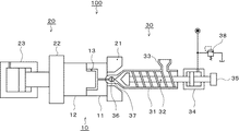
以下、本発明を実施するための最良の形態について、添付図面、フローチャート及びタイムチャートを参照しながら詳細に説明する。初めに、本発明に使用する射出成形機100の構成について説明する。図1に示すように、本発明に使用する射出成形機100は、金型10、型締装置20、射出装置30及び図示しない型締装置20と射出装置30を制御する制御装置とを備えている。
金型10は、固定盤21に取り付けられた固定金型11と可動盤22に取り付けられた可動金型12とからなり、型締装置20に設けられた金型10を開閉する型締シリンダ23により可動盤22及び可動金型12は前後進できるように構成されている。可動盤22及び可動金型12は、図示しないタイバーにより案内され固定金型11及び固定盤21に対して前後進する。符号13は、固定金型11と可動金型12とにより形成される金型10のキャビティ空間である。
Hereinafter, the best mode for carrying out the present invention will be described in detail with reference to the accompanying drawings, flowcharts, and time charts. First, the configuration of the
The
次に、射出装置30の構成について説明する。図1に示す射出装置30は、シリンダバレル31と、シリンダバレル31内に内装されフライトを有するスクリュ32と、シリンダバレル31内に成形樹脂材料を供給するホッパ33とを備え、該スクリュ32を前後進させるスクリュ移動手段34と、該スクリュ32を回転駆動するスクリュ回転手段35が設けられている。そして、前記シリンダバレル31の外周面には、図示しないヒータが取り付けられている。
Next, the configuration of the injection device 30 will be described. An injection device 30 shown in FIG. 1 includes a
前記射出装置30は、スクリュ回転手段35によってスクリュ32が回転することにより、ホッパ33からペレット状の成形樹脂材料がシリンダバレル31に供給される構成となっており、該供給されたペレット状の成形樹脂材料は、シリンダバレル31に取り付けられたヒータよって加熱され、又、スクリュ32の回転によって混練圧縮作用を受けることで溶融しスクリュ32の前方へ送られる。スクリュ32の前方へ送られた溶融樹脂は、スクリュ移動手段34により前進するスクリュ32によって、バレル31の先端に取り付けられたノズル36からキャビティ空間13へ射出充填することができる。ノズル36には、溶融樹脂のシャットオフ手段37が設けられており、閉じた状態でスクリュ32を回転させたときに、ノズル36先端から外部へ溶融樹脂が漏れ出すことを防止する。
The injection device 30 is configured such that a pellet-shaped molding resin material is supplied from the
図1に示すように、本発明で使用する射出装置30のスクリュ移動手段34及びスクリュ回転手段35に油圧の駆動手段を用いる構成としたが、この構成に限らず、電動サーボモータを駆動手段に用いる構成であっても良い。
又、型締装置20は油圧駆動の型締シリンダ23を用いる直圧式型締機構としたが、トグル機構を電動サーボモータで駆動する構成であっても良い。
As shown in FIG. 1, the hydraulic drive unit is used for the
Further, although the
そして、図示しない前記制御装置は、型締装置20を制御する型締側制御部と型締条件を設定する型締条件設定器、及び射出装置を制御する射出制御部と射出条件、樹脂替え及び色替え条件を設定する射出条件設定器とを備え、連続成形運転を中断することなく樹脂替え及び色替えが行える構成となっている。
The control device (not shown) includes a mold clamping side control unit that controls the
次いで、図1、図2及び図3により本発明の樹脂替え及び色替え方法について説明する。本発明の樹脂替え及び色替え方法は以下の工程となっている。
(a)所定のスクリュ前進位置で所定時間スクリュを連続回転させる第1工程。
(b)前記連続生産運転時と同じ計量背圧及びスクリュ回転数の条件で樹脂を可塑化して計量する第2工程。
(c)金型を型閉じして、前記連続生産運転と同じ射出保圧の圧力、速度及び速度配分の条件で前記金型のキャビティ空間内に前記第2工程で可塑化した溶融樹脂を充填して成形体を得る第3工程。
(d)所定時間冷却保持の後に、金型を型開きして前記成形体を金型から取出す第4工程。
Next, the resin change and color change method of the present invention will be described with reference to FIGS. The resin changing and color changing methods of the present invention are as follows.
(A) A first step of continuously rotating the screw for a predetermined time at a predetermined screw advance position.
(B) A second step in which the resin is plasticized and measured under the same measurement back pressure and screw rotation speed conditions as in the continuous production operation.
(C) Closing the mold and filling the cavity space of the mold with the molten resin plasticized in the second step under the same injection holding pressure, speed and speed distribution conditions as in the continuous production operation. And a third step of obtaining a molded body.
(D) A fourth step of opening the mold and taking out the molded body from the mold after cooling and holding for a predetermined time.
図2及び3に示すように、樹脂替え及び色替え運転モードへの移行は、先ず、連続生産運転中に材料の供給を切り替えるとともに、残留する樹脂量と成形品との関係から算出した樹脂混じり又は色混じりのない生産ショット数Nを成形して連続生産運転を終了する。
連続生産運転の終了は、型締装置では型開きを完了して成形品を取出した状態である。連続生産運転の最後の生産ショットにおいて、射出充填の完了後に計量動作は樹脂替え及び色替え運転モードに切り替わる。即ち、連続生産運転の最後の生産ショットと樹脂替え及び色替え運転モードはラップ動作することになる。両者のラップ動作はシャットオフ手段37によって可能となる。なお射出成形機にシャットオフ手段37が装備されていない場合には、例えば金型内の樹脂流路にバルブゲート手段等の樹脂流路閉鎖手段が装備されていれば可能である。このラップ動作は樹脂替え及び色替え運転モードでの生産ショット間でも適用される。樹脂流路閉鎖手段が装備されていない場合には、前の生産ショットの型開・製品取出し工程の開始を樹脂替え及び色替え運転モードの第1工程及び第2工程の終了のタイミングまで遅らせて対応することになる。
そして、樹脂替え及び色替え運転モードへの切り替えは、予め設定された連続生産運転の生産ショット数の残数が生産ショット数Nと一致したことを検出することにより行う。
As shown in FIGS. 2 and 3, the transition to the resin change and color change operation mode is performed by first switching the material supply during the continuous production operation and mixing the resin calculated from the relationship between the amount of residual resin and the molded product. Alternatively, the production shot number N with no color mixture is formed, and the continuous production operation is finished.
The end of the continuous production operation is a state in which the mold opening is completed in the mold clamping device and the molded product is taken out. In the last production shot of the continuous production operation, the weighing operation is switched to the resin change and color change operation mode after the injection filling is completed. That is, the last production shot of the continuous production operation and the resin change and color change operation modes are lap operations. Both lap operations can be performed by the shut-off means 37. If the injection molding machine is not equipped with the shut-off means 37, it is possible, for example, if the resin flow path in the mold is equipped with a resin flow path closing means such as a valve gate means. This lapping operation is also applied between production shots in the resin change and color change operation modes. If the resin channel closing means is not equipped, the start of the mold opening / product removal process of the previous production shot is delayed until the end of the first process and the second process in the resin change and color change operation modes. Will respond.
Then, switching to the resin change and color change operation modes is performed by detecting that the remaining number of production shots in the continuous production operation set in advance matches the number N of production shots.
着色した同一樹脂材料の色の切り替えは、例えば、ホッパ33をツインホッパ構造としておき、いずれか一方のホッパを選択的に使用することによって行う。又、同一樹脂材料で着色剤(ドライカラー、カラーマスターバッチなど)により成形を行う場合における色の切り替えは、例えば、着色剤の供給手段を色の必要数だけ準備しておき、所望する色の着色剤の供給手段に変更することによって行うことができる。
The color of the same resin material that has been colored is switched by, for example, setting the
このようにして移行した樹脂替え及び色替え運転モードの(a)第1工程では、図3で示す所定のスクリュ前進位置で所定時間スクリュ32を連続回転させる。スクリュ32は連続生産運転時における回転数により回転駆動される。この工程ではスクリュ32の回転により溶融樹脂がスクリュ前方へ押し出され、ノズル36を介して金型のキャビティ空間13内に流入しないようにシャットオフ手段37を閉じた状態とする。更に、所定のスクリュ前進位置で所定時間スクリュ32の連続回転を実現させるために、スクリュ移動手段34に設けた圧力調整弁38をスクリュ32から押し出される樹脂圧の反力でも後退しない計量背圧BP2が作用する設定とし、スクリュ32が回転してもスクリュ前進位置を保持する構成となっている。スクリュ32の回転時間は、スクリュ回転時間Tにより設定する。
In the (a) first step of the resin change and color change operation modes thus transferred, the
スクリュ前進位置で所定時間スクリュ32を連続回転させることにより、スクリュ前進位置とすることでスクリュ32とシリンダバレル31先端部の内壁面との距離を小さくし、スクリュ32とシリンダバレル31先端部の内壁面との間に薄い溶融樹脂層を形成させ、薄い溶融樹脂層に強い回転せん断力が発生し、この強い回転せん断力を利用してシリンダバレル31先端部内壁面の滞留樹脂の掻き取り力が高く、樹脂や色の滞留が多い箇所を優先的に樹脂及び色替えさせるので、効率の良い樹脂及び色替えが実現でき、樹脂及び色替えの時間を短縮することができる。なおスクリュ32の回転数は連続生産運転時と同じとさせたが、掻き取り力を増すために回転数を高く変化させても良い。
又、サーボモータによる電動駆動の射出装置を用いる場合には、スクリュ移動手段のサーボモータにトルクを出力することで、スクリュ後部に計量背圧を作用させることが可能となる。
By continuously rotating the
In addition, when an electrically driven injection device using a servo motor is used, a torque back pressure can be applied to the rear portion of the screw by outputting torque to the servo motor of the screw moving means.
(b)第2工程では、連続生産運転時と同じ計量背圧BP1及びスクリュ回転数の条件で樹脂を可塑化して計量する。こうすることによって、可塑化計量した溶融樹脂の状態を連続生産運転時とほぼ同等にでき、後工程の射出充填条件と合わさって連続生産運転時と同様な成形品が得られ、生産運転を中断することを回避することができる。
また、第1工程から第2工程へ移行するときに圧力調整弁38で設定される計量背圧はBP2からBP1へ設定が変更され、所定の背圧降圧時間t1により降圧速度の勾配が決定される。背圧降圧時間が長いときはバレル31の樹脂圧力は緩やかに低下し、短いときは急激な圧力低下を招き溶融樹脂内に残留する空気や溶融樹脂の熱分解発生ガスなどを泡状に発生させ(気体が溶解された飽和溶液から急激な圧力低下によって気体成分が抽出される原理と同じ)、射出充填時に泡状のガスなどが噴出して、ノズル36内や金型ホットランナ内の残留樹脂を強制排出する効果を発揮する。
計量完了位置S1は、連続生産運転時と同じ条件で行う。
(B) In the second step, the resin is plasticized and weighed under the same conditions of the measurement back pressure BP1 and screw rotation speed as in the continuous production operation. By doing this, the state of the plasticized and weighed molten resin can be made almost the same as in continuous production operation, and the same molded product as in continuous production operation can be obtained when combined with injection filling conditions in the subsequent process, and production operation is interrupted. Can be avoided.
In addition, the measurement back pressure that is set by the
The measurement completion position S1 is performed under the same conditions as in the continuous production operation.
(c)第3工程では、金型を型閉じして、前記連続生産運転と同じ射出保圧の圧力、速度及び速度配分の条件で前記金型のキャビティ空間内に第2工程で可塑化した溶融樹脂を充填して成形体を得る。第2工程の連続生産運転時と同じ計量背圧BP1及びスクリュ回転数の条件で樹脂を可塑化して計量と合わさって、連続生産運転時とほぼ同等な成形品を成形することができ、生産運転を中断するトラブルを回避できる。
ただし、第2工程及び第3工程を連続生産運転時の条件と同じとしているが、連続生産運転時とは異なる第1工程が含まれているために、連続生産運転時とは溶融樹脂の密度が異なる可能性がある。そこで、射出工程におけるクッション位置C2を検出し、連続生産運転時におけるクッション位置C1との偏差量δ1を算出、該検出した偏差量に基づき2回目以降の計量完了位置S1をδ2補正し計量完了位置S2を決定する。偏差量δ1と補正量δ2とは同じ値である。こうすることにより、連続生産運転時と限りなく近い運転条件となり、生産運転を中断するといったトラブルは確実に回避できる。さらに、クッション位置を連続生産運転時と同じとすることによって、樹脂替え及び色替え運転モードから連続生産運転モードへの切り替えがスムーズに行われるメリットもある。
又、同様に検出した偏差量δ1により射出工程における速度の切り替え位置を補正し、2回目以降の射出速度の切り替えを決定する。
(C) In the third step, the mold was closed and plasticized in the cavity space of the mold in the second step under the same injection holding pressure, speed and speed distribution conditions as in the continuous production operation. Filled with molten resin to obtain a molded body. By plasticizing the resin under the same measurement back pressure BP1 and screw rotation speed conditions as in the second process continuous production operation, it is possible to form a molded product almost equivalent to that in the continuous production operation. Can avoid the trouble of interrupting.
However, the second process and the third process are the same as the conditions in the continuous production operation, but the first process is different from that in the continuous production operation. May be different. Therefore, the cushion position C2 in the injection process is detected, a deviation amount δ1 from the cushion position C1 in the continuous production operation is calculated, and the measurement completion position S1 after the second time is corrected by δ2 based on the detected deviation amount, and the measurement completion position. S2 is determined. The deviation amount δ1 and the correction amount δ2 are the same value. By doing so, the operating conditions are almost as close as those during continuous production operation, and troubles such as interruption of production operation can be reliably avoided. Furthermore, by making the cushion position the same as in the continuous production operation, there is an advantage that the switching from the resin change and color change operation modes to the continuous production operation mode can be performed smoothly.
Similarly, the position of speed change in the injection process is corrected by the detected deviation amount δ1, and the second and subsequent injection speed changes are determined.
(d)第4工程では、所定時間冷却保持の後に、可動金型12を型開きして成形体を金型装置10から取出す。これにより樹脂替え及び色替え運転モードの1回の成形サイクルが終了し、この成形サイクルを所定回数繰り返す。所定の回数繰り返して樹脂替え及び色替え運転モードから連続生産運転モードへ切り替え、新しい樹脂の連続生産運転へと移行する。
新しい樹脂の連続生産運転への移行に際しても、樹脂替え及び色替え運転生産と連続生産運転はラップ動作されるが、成形品の品質確認などのために生産を一時停止させても良い。
(D) In the fourth step, after cooling for a predetermined time, the
In the transition to the continuous production operation of a new resin, the resin change and color change operation production and the continuous production operation are lapped, but the production may be temporarily stopped for quality confirmation of the molded product.
以上のように、可塑化計量条件及び射出保圧条件が連続生産運転と同じであること、クッション位置の変化に応じて計量完了位置や射出速度の切り替え位置を補正して修正するので、製品はショットショットやオーバーパック(バリ不良)等の成形不良が発生することがないので安定成形ができ、連続生産運転中に樹脂又は色替え運転を行っても成形運転が中断することがない。さらに、樹脂や色の滞留が多い箇所を優先的に樹脂及び色替えさせるので、効率の良い樹脂及び色替えが実現でき、樹脂及び色替えの時間を短縮することができる。 As described above, the plasticizing measurement conditions and injection pressure holding conditions are the same as those in continuous production operation, and the measurement completion position and injection speed switching position are corrected and corrected according to the change in cushion position. Since molding defects such as shot shots and overpacks (burr defects) do not occur, stable molding can be performed, and molding operations are not interrupted even if resin or color change operations are performed during continuous production operations. In addition, since the resin and color change are preferentially performed at locations where the resin or color stays a lot, efficient resin and color change can be realized, and the resin and color change time can be shortened.
本発明の実施例と比較例とにより、本発明の優れた効果を説明する。成形には、射出成形機として横型トグル式電動駆動射出成形機(宇部興産機械製 MD850S−V射出成形機)を、樹脂材料として自動車内装用ポリプロピレン(プライムポリマー製 MRF=35)を用い、旧色を黒のマスターバッチ(東京インク製 3%添加)から新色を白(マスターバッチ無し)に色替えした。
成形品としては350×350の板状品で、質量は480グラムである。樹脂温度の設定は190℃とした。
黒色の成形を行う途中で黒色のマスターバッチの供給を停止し、成形品に色混じりが出始めてから、色替えモードに切り替えて連続成形運転を行い、色混じりの無い良品が得えられた成形回数で色替えの完了を確認する方法で行った。
The excellent effect of the present invention will be described with reference to examples of the present invention and comparative examples. For molding, a horizontal toggle type electric drive injection molding machine (MD850S-V injection molding machine manufactured by Ube Industries) is used as an injection molding machine, and polypropylene for automobile interior (MRF = 35 manufactured by prime polymer) is used as a resin material. The new color was changed from black masterbatch (manufactured by Tokyo Ink 3%) to white (no masterbatch).
The molded product is a 350 × 350 plate-shaped product with a mass of 480 grams. The resin temperature was set to 190 ° C.
During the black molding process, the black masterbatch supply was stopped, and after the color mixture started to appear in the molded product, the color change mode was switched to the continuous molding operation to obtain a good product with no color mixture. It was done by confirming the completion of color change by the number of times.
[実施例1]
実施例1として、スクリュ32の回転数と計量背圧BP1及び射出保圧を連続生産運転と同一に設定し、第1工程の計量背圧PB2を連続生産運転時より20MPa高く、スクリュ回転時間Tを10秒に、背圧降圧時間t1を10秒に、計量完了位置を補正した色替計量完了位置S2に設定し、色替え運転を行った。連続成形運転が行えたと共に、成形回数10回で色混じりのない良品を得た。
[Example 1]
As Example 1, the rotational speed of the
[実施例2]
実施例2として、第1工程の計量背圧BP2を実施例1より高く設定した成形例を説明する。スクリュ32の回転数と計量背圧BP1及び射出保圧を連続生産運転と同一に設定し、第1工程の計量背圧PB2を連続生産運転時より50MPa高く、スクリュ回転時間Tを10秒に、背圧降圧時間t1を10秒に、計量完了位置を補正した色替計量完了位置S2に設定し、色替え運転を行った。連続成形運転が行えたと共に、成形回数5回で色混じりのない良品を得た。
[Example 2]
As Example 2, a molding example in which the measured back pressure BP2 in the first step is set higher than Example 1 will be described. The rotational speed of the
[実施例3]
実施例3として、第1工程のスクリュ回転時間Tと背圧降圧時間t1を実施例2より短く、設定した成形例を説明する。スクリュ32の回転数と計量背圧BP1及び射出保圧を連続生産運転と同一に設定し、第1工程の計量背圧PB2を連続生産運転時より50MPa高く、スクリュ回転時間Tを5秒に、背圧降圧時間t1を1秒に、計量完了位置を補正した色替計量完了位置S2に設定し、色替え運転を行った。連続成形運転が行えたと共に、成形回数3回で色混じりのない良品を得た。
[Example 3]
As Example 3, a molding example in which the screw rotation time T and the back pressure reduction time t1 in the first step are set shorter than in Example 2 will be described. The rotational speed of the
[比較例1]
比較例1としての成形例を説明する。使用した射出成形機、成形材料、成形品は実施例と同じである。
色替連続運転時の成形条件を連続生産運転時と同じ条件に設定し、色替え運転を行った。連続成形運転は行えたが、成形回数50回でも色混じりのない良品を得ることができなかった。
[Comparative Example 1]
A molding example as Comparative Example 1 will be described. The injection molding machine, molding material, and molded product used are the same as in the examples.
The molding conditions during color change continuous operation were set to the same conditions as during continuous production operation, and color change operation was performed. Although the continuous molding operation could be performed, a good product with no color mixture could not be obtained even with 50 moldings.
[比較例2]
次に,比較例2として、実施例1の色替運転における計量完了位置S2を連続生産運転における計量完了位置S1に変更した以外は、同じ条件に設定し色替え運転を行った。オーバーパック(バリ不良)が発生して連続運転が中断し、連続成形運転を継続することができなかった。
[Comparative Example 2]
Next, as Comparative Example 2, the color change operation was performed under the same conditions except that the measurement completion position S2 in the color change operation of Example 1 was changed to the measurement completion position S1 in the continuous production operation. An overpack (burr failure) occurred and the continuous operation was interrupted, and the continuous molding operation could not be continued.
[比較例3]
比較例3として、連続生産運転時の計量条件を同じとし、射出条件を射出・後退の寸動射出に設定して色替え運転を行った。ショートショットが発生して連続運転が中断し、連続成形運転を継続することができなかった。
[Comparative Example 3]
As Comparative Example 3, the color change operation was performed by setting the same weighing conditions during the continuous production operation and setting the injection condition to injection / reverse inching injection. A short shot occurred, the continuous operation was interrupted, and the continuous molding operation could not be continued.
以上説明したように、本発明では、可塑化計量工程の前に高い計量背圧を設定してスクリュ位置を保持し、所定の前進限位置でスクリュを連続回転させるので、スクリュ回転による樹脂の掻き取り力によって残留する旧樹脂の剥離が促進され、樹脂や色の滞留が多い箇所を優先的に樹脂及び色替えさせるので、効率の良い樹脂及び色替えが実現でき、色替えに要する樹脂量と時間を削減することができる。
又、初回の色替え射出工程のデータを検出して2回目以降の計量位置や射出工程の速度切り替え位置を補正する構成としたので、ショートショット(充填不足)やオーバーパック(充填過剰)等の成形不良が防止され、樹脂替え及び色替え運転を連続して行うことができ、射出成形機の連続成形運転を中断することがない。
As described above, according to the present invention, since the screw position is maintained by setting a high measurement back pressure before the plasticizing and measuring step and the screw is continuously rotated at a predetermined forward limit position, the resin is scraped by rotating the screw. Peeling of the remaining old resin is promoted by the take-off force, and the resin and the color change are preferentially changed in the resin and the portion where the color stays, so that an efficient resin and color change can be realized, and the amount of resin required for the color change Time can be saved.
In addition, since the first color change injection process data is detected and the measurement position for the second time and the speed switching position of the injection process are corrected, short shot (underfilling), overpack (overfilling), etc. Molding defects are prevented, resin replacement and color change operation can be performed continuously, and the continuous molding operation of the injection molding machine is not interrupted.
10 金型
11 固定金型
12 可動金型
13 キャビティ空間
20 型締装置
21 固定盤
22 可動盤
23 型締シリンダ
30 射出装置
31 シリンダバレル
32 スクリュ
33 ホッパ
34 スクリュ移動手段
35 スクリュ回転手段
36 ノズル
37 シャットオフ手段
38 圧力調整弁
BP1 連続生産運転時の計量背圧
BP2 色替え運転時の計量背圧
C1 連続生産運転時のクッション位置
C2 色替え運転時のクッション位置
S1 連続生産運転時の計量完了位置
S2 色替え運転時の計量完了位置
N 色混じりのない良品ショット数
T スクリュ回転時間
t1 背圧降圧時間
δ1 クッション位置の偏差量(スクリュストローク差)
δ2 偏差量と同等の補正量
T1 連続生産運転時の射出速度の切り替え位置
T2 色替え成形運転時の射出速度の切り替え位置
DESCRIPTION OF
δ2 Correction amount equivalent to deviation T1 Injection speed switching position during continuous production operation T2 Injection speed switching position during color change molding operation
Claims (4)
樹脂又は色の供給を切り替えてから製品に樹脂又は色混じりが発生する生産ショット数を予め求めておき、前記定めた生産ショット数を成形後に、
所定のスクリュ前進位置で所定時間スクリュを連続回転させる第1工程と、
前記連続生産運転時と同じ計量背圧及びスクリュ回転数の条件で樹脂を可塑化して計量する第2工程と、
金型を型閉じして、前記連続生産運転と同じ射出保圧の圧力、速度及び速度配分の条件で前記金型のキャビティ空間内に前記第2工程で可塑化した溶融樹脂を充填して成形体を得る第3工程と、
所定時間冷却保持の後に、金型を型開きして前記成形体を金型から取出す第4工程と、からなる樹脂替え及び色替え運転モードに移行し、
前記第1工程から第4工程を予め設定した回数繰り返して前記樹脂替え及び色替え運転モードを終了し、
次いで、前記連続生産運転に移行することを特徴とする射出成形機の樹脂替え及び色替え方法。 In resin change and color change methods of injection molding machines that change resin or color during continuous production operation,
After switching the resin or color supply, the number of production shots where resin or color mixing occurs in the product is determined in advance, and after molding the determined number of production shots,
A first step of continuously rotating the screw for a predetermined time at a predetermined screw advance position;
A second step of plasticizing and weighing the resin under the same measurement back pressure and screw rotation speed conditions as in the continuous production operation;
The mold is closed and filled with the molten resin plasticized in the second step into the cavity space of the mold under the same injection holding pressure, speed and speed distribution conditions as in the continuous production operation. A third step of obtaining a body;
After cooling and holding for a predetermined time, the mold is opened and the fourth step of taking out the molded body from the mold, and the process shifts to a resin change and color change operation mode,
The resin change and color change operation modes are completed by repeating the first to fourth steps a predetermined number of times,
Next, a method for changing the resin and changing the color of the injection molding machine, wherein the process is shifted to the continuous production operation.
Priority Applications (1)
| Application Number | Priority Date | Filing Date | Title |
|---|---|---|---|
| JP2011003770A JP5704392B2 (en) | 2011-01-12 | 2011-01-12 | Resin change and color change method of injection molding machine |
Applications Claiming Priority (1)
| Application Number | Priority Date | Filing Date | Title |
|---|---|---|---|
| JP2011003770A JP5704392B2 (en) | 2011-01-12 | 2011-01-12 | Resin change and color change method of injection molding machine |
Publications (2)
| Publication Number | Publication Date |
|---|---|
| JP2012143960A true JP2012143960A (en) | 2012-08-02 |
| JP5704392B2 JP5704392B2 (en) | 2015-04-22 |
Family
ID=46788048
Family Applications (1)
| Application Number | Title | Priority Date | Filing Date |
|---|---|---|---|
| JP2011003770A Active JP5704392B2 (en) | 2011-01-12 | 2011-01-12 | Resin change and color change method of injection molding machine |
Country Status (1)
| Country | Link |
|---|---|
| JP (1) | JP5704392B2 (en) |
Cited By (3)
| Publication number | Priority date | Publication date | Assignee | Title |
|---|---|---|---|---|
| JP2017001338A (en) * | 2015-06-14 | 2017-01-05 | 東洋インキScホールディングス株式会社 | Liquid colorant corresponding melting discharge device and liquid colorant injection device, and method for controlling liquid colorant corresponding melting discharge device |
| JP2018034344A (en) * | 2016-08-30 | 2018-03-08 | 東洋インキScホールディングス株式会社 | Liquid coloring agent supply control device |
| JP2019062798A (en) * | 2017-09-29 | 2019-04-25 | 日清オイリオグループ株式会社 | Continuous production method and system of edible oils which have different fatty acid inclusion ratio |
Citations (7)
| Publication number | Priority date | Publication date | Assignee | Title |
|---|---|---|---|---|
| JPS53101058A (en) * | 1977-02-15 | 1978-09-04 | Ube Ind Ltd | Changeover of material and color in injection molding machine |
| JPH0345114U (en) * | 1989-09-12 | 1991-04-25 | ||
| JPH05337946A (en) * | 1992-06-11 | 1993-12-21 | Sumitomo Jukikai Plast Mach Kk | Hot-runner color changing method |
| JPH07125003A (en) * | 1993-11-02 | 1995-05-16 | Toyota Auto Body Co Ltd | Method and device for exchanging material and color in injection molding machine |
| JPH1128753A (en) * | 1997-07-10 | 1999-02-02 | Mitsubishi Heavy Ind Ltd | Resin/color replacing method in injection molding machine |
| JP2003300224A (en) * | 2002-04-09 | 2003-10-21 | Toyota Motor Corp | Method for changing color of resin in injection molding |
| JP2008195023A (en) * | 2007-02-15 | 2008-08-28 | Toyo Mach & Metal Co Ltd | Injection molding machine |
-
2011
- 2011-01-12 JP JP2011003770A patent/JP5704392B2/en active Active
Patent Citations (7)
| Publication number | Priority date | Publication date | Assignee | Title |
|---|---|---|---|---|
| JPS53101058A (en) * | 1977-02-15 | 1978-09-04 | Ube Ind Ltd | Changeover of material and color in injection molding machine |
| JPH0345114U (en) * | 1989-09-12 | 1991-04-25 | ||
| JPH05337946A (en) * | 1992-06-11 | 1993-12-21 | Sumitomo Jukikai Plast Mach Kk | Hot-runner color changing method |
| JPH07125003A (en) * | 1993-11-02 | 1995-05-16 | Toyota Auto Body Co Ltd | Method and device for exchanging material and color in injection molding machine |
| JPH1128753A (en) * | 1997-07-10 | 1999-02-02 | Mitsubishi Heavy Ind Ltd | Resin/color replacing method in injection molding machine |
| JP2003300224A (en) * | 2002-04-09 | 2003-10-21 | Toyota Motor Corp | Method for changing color of resin in injection molding |
| JP2008195023A (en) * | 2007-02-15 | 2008-08-28 | Toyo Mach & Metal Co Ltd | Injection molding machine |
Cited By (3)
| Publication number | Priority date | Publication date | Assignee | Title |
|---|---|---|---|---|
| JP2017001338A (en) * | 2015-06-14 | 2017-01-05 | 東洋インキScホールディングス株式会社 | Liquid colorant corresponding melting discharge device and liquid colorant injection device, and method for controlling liquid colorant corresponding melting discharge device |
| JP2018034344A (en) * | 2016-08-30 | 2018-03-08 | 東洋インキScホールディングス株式会社 | Liquid coloring agent supply control device |
| JP2019062798A (en) * | 2017-09-29 | 2019-04-25 | 日清オイリオグループ株式会社 | Continuous production method and system of edible oils which have different fatty acid inclusion ratio |
Also Published As
| Publication number | Publication date |
|---|---|
| JP5704392B2 (en) | 2015-04-22 |
Similar Documents
| Publication | Publication Date | Title |
|---|---|---|
| EP2735418B1 (en) | Injection molding machine and raw material metering unit | |
| JP5574081B2 (en) | Injection molding machine and injection molding method | |
| JP5704392B2 (en) | Resin change and color change method of injection molding machine | |
| JP5552780B2 (en) | Injection molding apparatus and injection molding method | |
| KR20060033017A (en) | Molding method, purging method, and molding machine | |
| JP4146509B1 (en) | Injection molding machine and injection molding method using the same | |
| JP6026219B2 (en) | Injection molding machine | |
| TW201343364A (en) | Injection molding machine | |
| JP5022734B2 (en) | Injection molding machine | |
| JP5924588B2 (en) | Injection apparatus and injection molding method for injection molding machine | |
| JP2014184702A (en) | Injection molding method and device | |
| JP2023059073A (en) | injection molding method | |
| JP4996365B2 (en) | Pre-plastic injection molding equipment | |
| JP2009040023A (en) | Method and apparatus for feeding nitrogen gas to injection molding machine | |
| JP2002192569A (en) | Material replacing device in mold, and material replacing method using the same | |
| JP2006272670A (en) | Preplasticating type injection molding machine | |
| WO2011065143A1 (en) | Injection device and resin injection method | |
| JP2006327091A (en) | Method for manufacturing thick-walled molded article | |
| JP2009006526A (en) | Preplasticization injection molding machine | |
| JP2023045616A (en) | injection molding method | |
| JP2004066691A (en) | Injection molding method and apparatus | |
| JP6026220B2 (en) | Injection molding machine | |
| JPH02202416A (en) | Preplasticizing type injection molding machine | |
| JP5329190B2 (en) | Injection molding machine | |
| JP6036283B2 (en) | Injection machine for injection molding machine |
Legal Events
| Date | Code | Title | Description |
|---|---|---|---|
| A621 | Written request for application examination |
Free format text: JAPANESE INTERMEDIATE CODE: A621 Effective date: 20131108 |
|
| A977 | Report on retrieval |
Free format text: JAPANESE INTERMEDIATE CODE: A971007 Effective date: 20140924 |
|
| A131 | Notification of reasons for refusal |
Free format text: JAPANESE INTERMEDIATE CODE: A131 Effective date: 20140926 |
|
| A521 | Request for written amendment filed |
Free format text: JAPANESE INTERMEDIATE CODE: A523 Effective date: 20141031 |
|
| TRDD | Decision of grant or rejection written | ||
| A01 | Written decision to grant a patent or to grant a registration (utility model) |
Free format text: JAPANESE INTERMEDIATE CODE: A01 Effective date: 20150129 |
|
| A61 | First payment of annual fees (during grant procedure) |
Free format text: JAPANESE INTERMEDIATE CODE: A61 Effective date: 20150211 |
|
| R150 | Certificate of patent or registration of utility model |
Ref document number: 5704392 Country of ref document: JP Free format text: JAPANESE INTERMEDIATE CODE: R150 |
|
| R250 | Receipt of annual fees |
Free format text: JAPANESE INTERMEDIATE CODE: R250 |
|
| R250 | Receipt of annual fees |
Free format text: JAPANESE INTERMEDIATE CODE: R250 |
|
| R250 | Receipt of annual fees |
Free format text: JAPANESE INTERMEDIATE CODE: R250 |
|
| R250 | Receipt of annual fees |
Free format text: JAPANESE INTERMEDIATE CODE: R250 |
|
| R250 | Receipt of annual fees |
Free format text: JAPANESE INTERMEDIATE CODE: R250 |
|
| S533 | Written request for registration of change of name |
Free format text: JAPANESE INTERMEDIATE CODE: R313533 |
|
| R350 | Written notification of registration of transfer |
Free format text: JAPANESE INTERMEDIATE CODE: R350 |
|
| R250 | Receipt of annual fees |
Free format text: JAPANESE INTERMEDIATE CODE: R250 |
|
| R250 | Receipt of annual fees |
Free format text: JAPANESE INTERMEDIATE CODE: R250 |