JP2012143205A - Nucleic acid analyzer - Google Patents
Nucleic acid analyzer Download PDFInfo
- Publication number
- JP2012143205A JP2012143205A JP2011005387A JP2011005387A JP2012143205A JP 2012143205 A JP2012143205 A JP 2012143205A JP 2011005387 A JP2011005387 A JP 2011005387A JP 2011005387 A JP2011005387 A JP 2011005387A JP 2012143205 A JP2012143205 A JP 2012143205A
- Authority
- JP
- Japan
- Prior art keywords
- nucleic acid
- acid analyzer
- substrate
- flow path
- analyzer according
- Prior art date
- Legal status (The legal status is an assumption and is not a legal conclusion. Google has not performed a legal analysis and makes no representation as to the accuracy of the status listed.)
- Granted
Links
Images


Landscapes
- Investigating Or Analysing Biological Materials (AREA)
- Apparatus Associated With Microorganisms And Enzymes (AREA)
- Measuring Or Testing Involving Enzymes Or Micro-Organisms (AREA)
Abstract
Description
本発明は、微粒子に固定された生体分子の検出、並びに分析を行うために用いる核酸分析装置に関する。 The present invention relates to a nucleic acid analyzer used for detecting and analyzing biomolecules immobilized on fine particles.
DNAやRNAの塩基配列を決定する新しい技術が開発されてきている。 New techniques for determining the base sequences of DNA and RNA have been developed.
旧来、塩基配列の決定には電気泳動を利用した方法が用いられており、予め配列決定用のDNA断片又はRNA試料から逆転写反応を行い合成したcDNA断片試料を調製し、周知のサンガー法によるジデオキシ反応を実行した後、電気泳動を行い、分子量分離展開パターンを計測して解析していた。 Traditionally, a method using electrophoresis has been used to determine a base sequence. A cDNA fragment sample synthesized by performing a reverse transcription reaction from a DNA fragment or RNA sample for sequencing in advance is prepared, and a known Sanger method is used. After the dideoxy reaction, electrophoresis was performed, and molecular weight separation development patterns were measured and analyzed.
これに対し昨今、基板に試料となるDNA断片を数多く固定して、パラレルに数多くの断片の配列情報を決定する方法が開発され、塩基解析速度は飛躍的に向上した。 On the other hand, recently, a method for fixing a large number of DNA fragments as samples on a substrate and determining the sequence information of many fragments in parallel has been developed, and the base analysis speed has been dramatically improved.
例えば、非特許文献1では、DNA断片を担持する担体として微粒子を用い、核酸を結合させた微粒子をガラス基板上にランダムに固定することで、平面状に複数のサンプルを展開し、二次元画像センサを用いて測定することで多数のサンプルを平行して解析している。 For example, in Non-Patent Document 1, by using microparticles as a carrier for supporting a DNA fragment and fixing microparticles to which nucleic acids are bound on a glass substrate at random, a plurality of samples are developed in a planar shape, and a two-dimensional image is obtained. Many samples are analyzed in parallel by measuring using a sensor.
また近年では、更に塩基解読のスループットや解析結果の精度を高める目的で、担体を固定させる部位を限定する技術も開発されている。 In recent years, in order to further improve the throughput of base decoding and the accuracy of analysis results, a technique for limiting the site to which the carrier is immobilized has been developed.
例えば特許文献1では、解析対象の担体の配置が、二次元画像センサの画素配置に適した形態となるように、担体の固定に用いる足場を基板上に規則的に設置している。 For example, in Patent Document 1, a scaffold used for fixing the carrier is regularly placed on the substrate so that the carrier to be analyzed has a configuration suitable for the pixel arrangement of the two-dimensional image sensor.
解析対象となる担体の固定化は、基板表面の官能基と担体上の官能基との反応によって起こるものであり、固定化には両者の接触が必須となる。 The immobilization of the carrier to be analyzed occurs due to the reaction between the functional group on the substrate surface and the functional group on the carrier, and contact between the two is essential for immobilization.
しかしながら、特許文献1には、微粒子を基板上に投入した場合、微粒子が接触しないサイトが出てくる可能性がある。 However, in Patent Document 1, there is a possibility that when fine particles are put on a substrate, a site where the fine particles do not contact may appear.
本発明はこの課題を解決するためのものであり、その目的は、担体をなるべく高い確率で基板上に接触させる、核酸分析装置を提供することである。 The present invention has been made to solve this problem, and an object of the present invention is to provide a nucleic acid analyzer that makes a carrier contact with a substrate with as high a probability as possible.
本発明の核酸分析装置は、基板上の目的物質の解析を行う核酸分析装置であって、目的物質を結合させた担体を固定する基板と、基板との間に第一の流路と、反応領域とを形成する封止部材と、封止部材中に形成され第一の流路と連続した第二の流路と、を有し、第一の流路と第二の流路の構造がなす角度が5度〜90度である。 The nucleic acid analyzer of the present invention is a nucleic acid analyzer for analyzing a target substance on a substrate, a substrate on which a carrier to which the target substance is bound is fixed, a first channel between the substrate, a reaction And a second flow path formed in the sealing member and continuous with the first flow path, and the structure of the first flow path and the second flow path is The formed angle is 5 degrees to 90 degrees.
本発明によれば、基板表面における担体の局所的な濃度が向上することで、効率の良い固定化反応を行うことができる。結果、固定化反応時間の短縮と使用サンプル量の低減を図ることができる。 According to the present invention, since the local concentration of the carrier on the substrate surface is improved, an efficient immobilization reaction can be performed. As a result, the immobilization reaction time can be shortened and the amount of sample used can be reduced.
本発明の実施形態について、図を参照して説明する。 Embodiments of the present invention will be described with reference to the drawings.
〔実施例1:担体の慣性力を用いた濃度勾配の作成〕
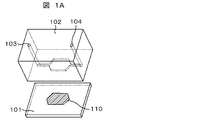
本発明の核酸分析反応用デバイスについて、図1A〜図1Cを用いて説明する。固定基板101の上に凹みを有する流路基板(封止部材)102を張り合わせることで、流入口103と流出口104の少なくとも二箇所以上の開口部を有し、固定基板101へ溶液を供給する流路系が形成される。流入口より核酸を固定した担体(微粒子,ビーズとも称する)105を含んだ溶液をポンプ106で送液する。
[Example 1: Preparation of concentration gradient using inertial force of carrier]
The nucleic acid analysis reaction device of the present invention will be described with reference to FIGS. 1A to 1C. By sticking a channel substrate (sealing member) 102 having a recess on the fixed
ここで、微細流路は、固定基板101を含む平面と平行な流路(微細流路)107と固定基板101を含む平面と交差する流路108を有しており、その交わる曲げ部109において担体105は自身の慣性力によって流路外周部へと濃縮される。基板と平行な流路内部は層流状態にあり、曲げ部109で形成された濃度勾配を保ったまま固定化反応の場である固定基板101表面へと供給する。
Here, the fine flow path has a flow path (fine flow path) 107 parallel to the plane including the
固定基板101の材質としては、ガラス基板,サファイア基板,シリコン基板などの無機物質からなる基板,ステンレスなどの金属からなる基板,ポリメタクリル酸メチル樹脂,ポリカーボネート樹脂,シクロオレフィン樹脂などの有機物質からなる基板を用いることができる。
As a material of the
流路基板102の材質に特に制限はないが1mm以下の加工が可能な材質と加工法の組み合わせが望まれる。例えば、ポリメタクリル酸メチル樹脂やシクロオレフィン樹脂などの熱可塑性樹脂への射出成型やナノインプリント加工,UV硬化樹脂を用いた光インプリント,シリコンや石英,ガラスなどへのフォトリソグラフィとエッチングを組み合わせた加工,PDMSなどの熱硬化性樹脂を金型に流し硬化させる加工法などがある。
The material of the
固定基板101と流路基板102との張り合わせには、ガラス同士,ガラスとPDMS,PDMS同士であれば、酸素プラズマ処理やエキシマUV照射を行った後に張り合わせることで両者を強固に接合させることができる。また、一方が熱可塑性樹脂基板の場合は、ガラス転移温度まで加熱することで溶着することが可能である。
When the
流路基板102内部に形成された固定基板101を含む平面と交差する流路108は、内部の流れが層流となるように十分に微細かつ長さを有するものとする。具体的には、流路断面積4mm2以下、長さ1mm以上が望ましいが、内部流体のレイノルズ数が2300以下となり、層流支配な環境となるのであれば、これに限らない。
The
固定基板101と平行な微細流路107の長さは短いほうが好ましい。本発明の実施形態としては100mm以下が好ましく、10mm以下がより好ましい。また、基板と平行な微細流路107は必須ではなく、固定反応部110と縦方向の流路108を直接連結させる構造であってもかまわない。基板と平行な微細流路107の長さを短くすることで、曲げ部から固定基板101に溶液が到達する時間を短縮することができ、担体濃度勾配の拡散による解消を防ぐことができる。
The length of the
固定基板101を含む平面とそれと交差する流路108の交差角度は、1度以上であればよいがより好ましくは5度〜175度、さらに好ましくは90度の角度で交わることが望ましい。曲げ部において急激な方向変化をつけることで、担体にかかる慣性力の方向と流体の流れの方向との齟齬が大きくなり、より大きな担体濃度勾配を生むことができる。
The intersecting angle between the plane including the
固定基板101を含む平面と交差する流路108は、反応部よりも流入口側にと流出口側両方に存在することが望ましいが、一方であってもかまわない。
It is desirable that the
担体溶液を送液するポンプに特に指定はないが、往復送液が可能な機構を有するものが好ましい。往復送液を行うことで、復路時にも曲げ部109(排出口側)で担体濃度を高めた溶液を固定基板101表面に供給することができる。これによって、担体105の利用効率を向上することが可能となる。また反応に時間が掛かり担体の濃度勾配が拡散によって解消されてしまった場合も、往復送液を継続して行うことで、常に固定基板101近傍の担体濃度を高い状態に維持することができる。
A pump for feeding the carrier solution is not particularly specified, but a pump having a mechanism capable of feeding back and forth is preferable. By performing the reciprocating liquid supply, the solution having a higher carrier concentration can be supplied to the surface of the
本発明において、担体105と固定基板101との間の結合に制約はないが、例えばビオチンとアビジンの親和性や静電相互作用,疎水相互作用,共有結合,物理的な捕捉などを挙げることができる。いずれの手法も担体と基板が影響を及ぼしうる距離に存在する時に起こる確立依存の現象であり、効果範囲に存在する担体濃度を向上させることで、担体の固定率・基板の単位面積あたりの担体固定量を共に向上させることができる。
In the present invention, the binding between the
〔実施例2:電場による濃度勾配の形成〕
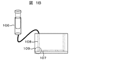
担体201がツェータ電位を有する場合、実施例1を構成する要素の微細流路曲げ部109の代わりに、微細流路202中の流体の流れと直交する位置に電極対203を設置し、電圧を印加することで担体の濃度勾配を作り出すことができる。この実施例について図2A,図2Bを用いて説明する。
[Example 2: Formation of concentration gradient by electric field]
When the
例えば、担体が微粒子であり負のツェータ電位を有する場合、固定基板側の電極対203に正電荷を遠位側の電極に負電荷を印加することで、正極側(つまり基板表面側)の担体濃度を高めることができる。この電場によって形成された、濃度勾配を有した担体溶液は実施例1と同様に固定反応基板204に供給され、効率的な固定化反応を行うことができる。
For example, when the carrier is a fine particle and has a negative zeta potential, by applying a positive charge to the
電極対203の位置は、流路内である必要はなく、流体の流れに直交する電場を形成できるように流路に沿って設置されていれば良い。電極を微細流路202の外に設置することで担体分散液の電気分解を防ぎつつ担体の濃度勾配を作り出すことができる。
The position of the
電極に印加する電圧は一定電圧であってもかまわないが、経時的に変化するものであってもかまわない。担体溶液中に含まれる担体201の濃度が希薄な場合には、強い電場をかけ担体を電極周囲に付着させ、溶液から分離させることで、担体濃度を増加させることができる。この工程により、たとえ希薄な担体溶液しか得られずとも、固定化反応に利用することができる。
The voltage applied to the electrode may be a constant voltage, or may change with time. When the concentration of the
また電場の強度だけでなく電荷の正負の方向も変化させてかまわない。この際の担体201は、正負いずれのツェータ電位を有していても良く、電極対203に印加する電圧を切り替えることで、幅広い種類の担体や溶液環境(pH・塩濃度など)に対応することができる。
In addition to the intensity of the electric field, the positive and negative directions of the charge may be changed. In this case, the
また図2Bに示すように、微細流路202を通る担体溶液中に核酸と結合した担体205と核酸を結合していない担体206とが含まれる場合、固定反応基板204側に正の電荷を印加することで、核酸は負の電荷を有しているため核酸と結合した担体205を優先的に濃縮することができる。すなわち、固定反応基板204の単位面積あたりの核酸固定濃度を向上させることができる。
As shown in FIG. 2B, when the carrier solution passing through the
〔実施例3:磁場による濃度勾配の作成〕
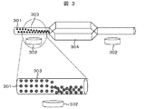
磁性担体301を用いる場合、実施例2を構成する要素の電極対203の代わりに、磁力源302(永久磁石または電磁石)を設置し、磁場によって担体の濃度勾配を作り出すことができる。この実施例について図3を用いて説明する。この磁力源302を微細流路303の固定反応基板304側に設けることで、固定反応基板304表面側の担体濃度を高めることができる。この磁場によって形成された、濃度勾配を有した担体溶液は実施例1と同様に固定反応基板304に供給され、効率的な固定化反応を行うことができる。
[Example 3: Creation of concentration gradient by magnetic field]
When the
微細流路303中での磁場の強度は、一定でもかまわないが任意に調整可能な機構を備えることが望ましい。すなわち、永久磁石を用いる場合であれば流路からの距離を可変とし、またあるいは微細流路303と磁力源302との間に磁気遮蔽物を挿入可能な構造とする。磁力源が電磁石の場合は、前述の永久磁石の場合に加えて電流量を制御することで、磁場の強度をコントロールできる。これにより磁性担体301密度に応じた適切な磁力設定が可能となる。
The strength of the magnetic field in the
磁力源302の位置は、固定反応基板304の直下であってもかまわないが、微細流路303上に設置することがより好ましい。磁力源302を固定反応基板304の直下に設ける場合は、担体固定密度の斑を避けるために、広い面積で均一な磁場を発生させる必要があるが、磁力源の位置を微細流路303にすることで、均一な磁場を要求する面積を小さくすることができ、磁力源の簡素化とコスト減少につながる。
The position of the
〔実施例4〕
本実施例では、核酸分析デバイスを用いた核酸分析装置の好ましい構成の一例について図4を参照しながら説明する。
Example 4
In the present embodiment, an example of a preferable configuration of a nucleic acid analyzer using a nucleic acid analysis device will be described with reference to FIG.
本実施例の核酸分析装置は、核酸分析デバイスに対して、蛍光色素を有するヌクレオチド,核酸合成酵素、及び核酸試料を供給する手段と、核酸分析デバイスに光を照射する手段と、核酸分析デバイス上においてヌクレオチド,核酸合成酵素、及び核酸試料が共存することにより起きる核酸伸長反応により核酸鎖中に取り込まれた蛍光色素の蛍光を測定する発光検出手段と、を備える。より具体的には、流路基板401と固定化基板402と溶液交換用口である注入口403と排出口404から構成される前記のデバイス405を設置する。なお、流路基板401には、PDMS(Polydimethylsiloxane)を使用する。YAGレーザ光源(波長532nm,出力20mW)407およびYAGレーザ光源(波長355nm,出力20mW)408から発振するレーザ光409および410を、レーザ光409のみをλ/4板411によって円偏光し、ダイクロイックミラー412(410nm以下を反射)によって、前記2つのレーザ光を同軸になるよう調整した後、レンズ413によって集光し、その後、プリズム414を介してデバイス405へ臨界角以上で照射する。
The nucleic acid analyzer of the present embodiment includes means for supplying a nucleotide having a fluorescent dye, a nucleic acid synthase, and a nucleic acid sample to the nucleic acid analysis device, means for irradiating the nucleic acid analysis device with light, and on the nucleic acid analysis device. And a luminescence detection means for measuring the fluorescence of the fluorescent dye incorporated into the nucleic acid chain by the nucleic acid extension reaction caused by the coexistence of the nucleotide, the nucleic acid synthase, and the nucleic acid sample. More specifically, the
以下、担体として直径50nm程度の金微粒子を用いた場合を例にとり、説明する。この場合、レーザ照射により、固定化基板402表面上に存在する金微粒子において局在型表面プラズモンが発生し、金微粒子に結合したDNAプローブにより捕捉された標的物質の蛍光体は蛍光増強場内に存在することになる。蛍光体はレーザ光で励起され、その増強された蛍光の一部は流路基板401の一部に設けられた検出窓406を介して出射される。また、検出窓406より出射される蛍光は、対物レンズ415(×60,NA1.35,作動距離0.15mm)により平行光束とされ、光学フィルタ416により背景光及び励起光が遮断され、結像レンズ417により2次元CCDカメラ418上に結像される。
Hereinafter, the case where gold fine particles having a diameter of about 50 nm are used as a carrier will be described as an example. In this case, localized surface plasmons are generated in the gold fine particles existing on the surface of the immobilized
逐次反応方式の場合には、蛍光色素付きヌクレオチドとして、P.N.A.S. 2006, vol. 103, pp 19635-19640(非特許文献2)に開示されているような、リボースの3′OHの位置に3′−O−アリル基を保護基として入れ、また、ピリミジンの5位の位置にあるいはプリンの7位の位置にアリル基を介して蛍光色素と結びつけたものが使用できる。アリル基は光照射(例えば波長355nm)あるいはパラジウムと接触することで切断されるため、色素の消光と伸長反応の制御を同時に達成することができる。逐次反応でも、未反応のヌクレオチドを洗浄で除去する必要はない。さらに、洗浄工程が必要ないことからリアルタイムで伸長反応を計測することも可能である。この場合には、前記ヌクレオチドにおいて、リボースの3′OHの位置に3′−O−アリル基を保護基として入れる必要は無く、光照射(例えば波長355nm)で切断可能な官能基を介して色素と結びついているヌクレオチドを用いれば良い。 In the case of the sequential reaction method, as a nucleotide with a fluorescent dye, 3′-position at the position of 3′OH of ribose as disclosed in PNAS 2006, vol. 103, pp 19635-19640 (Non-patent Document 2). An O-allyl group can be used as a protecting group, and the O-allyl group linked to a fluorescent dye via the allyl group at the 5-position of pyrimidine or at the 7-position of purine can be used. Since the allyl group is cleaved by light irradiation (for example, a wavelength of 355 nm) or contact with palladium, the quenching of the dye and the control of the extension reaction can be simultaneously achieved. Even in the sequential reaction, it is not necessary to remove unreacted nucleotides by washing. Furthermore, since no washing step is required, the extension reaction can be measured in real time. In this case, it is not necessary to add a 3′-O-allyl group as a protecting group at the 3′OH position of ribose in the nucleotide, and the dye is formed via a functional group that can be cleaved by light irradiation (for example, wavelength 355 nm). Nucleotides linked to can be used.
担体として、半導体微粒子を用いた場合にも、上述の核酸分析装置の例は適用可能である。例えば、半導体微粒子としてQdot(R)565 conjugate(インビトロジェン社製)を用いると、YAGレーザ光源(波長532nm,出力20mW)407で十分に励起できる。この励起エネルギーは532nmの光では励起されないアレクサ633(インビトロジェン社製)へ移動することにより蛍光を発するようになる。つまり、未反応のヌクレオチドに付随する色素は励起されることはなく、DNAプローブに捕捉され半導体微粒子に近接しエネルギー移動が起きてはじめて発光するので、捕捉されたヌクレオチドを蛍光測定で識別することが可能である。 The example of the nucleic acid analyzer described above can also be applied when semiconductor fine particles are used as the carrier. For example, when Qdot (R) 565 conjugate (manufactured by Invitrogen) is used as the semiconductor fine particles, it can be sufficiently excited with a YAG laser light source (wavelength 532 nm, output 20 mW) 407. This excitation energy emits fluorescence by moving to Alexa 633 (manufactured by Invitrogen), which is not excited by light of 532 nm. In other words, dyes associated with unreacted nucleotides are not excited, and are only captured by DNA probes and close to the semiconductor fine particles to emit light, so that the captured nucleotides can be identified by fluorescence measurement. Is possible.
上記のように、本実施例の核酸分析デバイスを用いて核酸分析装置を組み上げることにより核酸と結合した担体の固定化効率を高め、固定化時間の短縮,使用サンプル量の低減を図ることができる。 As described above, by assembling a nucleic acid analyzer using the nucleic acid analysis device of this example, it is possible to increase the immobilization efficiency of the carrier bound to the nucleic acid, shorten the immobilization time, and reduce the amount of sample used. .
〔実施例5〕
本発明に用いる固定化基板について、その好ましい構成の一例を、図5を用いて説明する。
Example 5
An example of a preferable configuration of the fixed substrate used in the present invention will be described with reference to FIG.
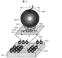
平滑支持基板501の上に接着パッド502が規則正しく、例えば図5に示すように格子状に形成されている。接着パッド502と微粒子503は、線状分子505を介して化学結合により結ばれている。線状分子505の末端の官能基506と、接着パッド502とは化学的相互作用により結合していることが好ましい。その際、官能基506は、平滑支持基板501との相互作用が弱く、接着パッド502との相互作用が強いことが好ましい。このような観点から、平滑基板としては、石英ガラス,サファイア,シリコン基板などを用いることができる。また、接着パッド502には、金,チタン,ニッケル,アルミから選ばれる材料で構成することができる。官能基506には、平滑支持基板501と接着パッド502との組み合わせを考えて選択せねばならないが、例えば、スルホヒドリル基,アミノ基,カルボキシル基,リン酸基,アルデヒド基等を用いることができる。線状分子505は、微粒子503と接着パッド502を結ぶ役割を果たし、長さに大きな限定はないが、低分子の場合には炭素数にして3から20程度の直鎖状分子が好ましい。線状分子505の末端の官能基507は、微粒子503との接着性をもたらす。また、線状分子505として高分子を用いる場合には、複数の側鎖を有し、官能基506を有する側鎖と官能基507を持つ側鎖を併せ持つものを用いることができる。微粒子503としては、金属微粒子や半導体微粒子を用いることができる。例えば、金の微粒子として、直径5nm〜100nmのものが市販されており、活用することができる。また、半導体微粒子としては、直径が10nm〜20nm程度のCdSe等の化合物半導体が市販されており、活用することができる。官能基507として用いることができる官能基は、微粒子の種類によって異なるが、例えば金微粒子を用いた場合にはスルホヒドリル基,アミノ基等が好ましい。半導体微粒子を用いる場合には、ストレプトアビジンで表面が修飾された微粒子が市販されており、官能基507としてビオチンを用いることができる。核酸分子504には、DNAやRNAの核酸分子を用いることができる。核酸分子の末端を官能基507と同様に予め修飾しておき、微粒子503と反応させておく。また、解析対象となる核酸分子と相補な領域を持つ核酸を微粒子503へ官能基507を介して結合させておき、ハイブリダイゼーションによって核酸分子504を微粒子503に結合させても良い。この相補領域を持つ核酸としてオリゴdTを用いることで、幅広くmRNAを捕捉することができる。一つの微粒子503に固定する核酸分子504は、一分子であることが好ましい。一つの微粒子503に一分子の核酸分子504を固定するためには、微粒子503の粒径が小さいほど好ましい。一つの核酸分子が微粒子表面に固定されると、微粒子上の電荷の状態が変化して、他の未固定の核酸分子の固定反応を阻害する効果が生じる。微粒子サイズが小さくなると、この効果が大きくなるからである。発明者らが鋭意検討した結果、微粒子サイズとして約20nm以下が好ましいことが判明している。また、微粒子503と核酸分子504との結合反応を液相で行い、かつ、微粒子503に対して核酸分子504の濃度を約1/10以下に下げて反応させることで、微粒子503の直径が1μm程度であっても、一つの微粒子503に固定する核酸分子504を一分子とすることができる。一方、微粒子503のサイズが大きくなるに従い、核酸分子504の固定密度が低下してしまう。簡便な蛍光検出で輝点を識別する場合回折限界を考慮すると輝点間が1μm程度離れていることが好ましい。したがって、微粒子503のサイズは1μm以下であることが適している。
接着パッド502を平滑支持基板501上に形成する方法としては、半導体で既に実用化されている薄膜プロセスを活用することができる。例えば、マスクを通した蒸着・スパッタリング、あるいは蒸着・スパッタリングにより薄膜を形成した後、ドライあるいはウエットエッチングにより製造することができる。規則正しく配置することは、薄膜プロセスを用いることで容易に実現できる。パッド間の間隔は任意に設定できるが、検出手段として光計測を行う場合、光検出の回折限界を考えると500nm以上が好ましい。
As a method for forming the
接着パッド502を平滑支持基板501上に形成した後、微粒子503と接着パッド502を結ぶ線状分子505を供給し、接着パッド502上に線状分子505を固定する。この際、平滑支持基板501上での非特異的吸着を防止する目的で、線状分子505を供給する前に、平滑支持基板501との接着力の強い材料を平滑支持基板501上に反応させる方法が有効である。例えば、シランカップリング剤等が利用できる。次に固定基板と流路基板を張り合わせ、核酸分子504を表面に固定させた微粒子503を基板上に供給して、微粒子503を接着パッド502上に固定させることにより、分析に用いることができる。
After the
接着パッド502上に微粒子503を固定させる際、一つの接着パッド502に複数個の微粒子503が固定される可能性がある。複数個が固定されてしまうと、種類の違う核酸断片の情報が重なり合ってしまい、正確な核酸分析ができなくなってしまう。そのため、一つの接着パッド502には、1個の微粒子503を固定させねばならない。そこで、発明者らは、種々の条件での固定実験を繰り返し、鋭意検討した結果、接着パッド502の直径dが微粒子503の直径Dに比べて小さい、という条件が成り立てば、一つの接着パッド502に1個の微粒子503を固定できることを見出した。接着パッド502に比べて同等以上の大きさの微粒子503が固定されると、未反応の線状分子が固定された微粒子に覆い隠されてしまい、別の微粒子と反応できなくなってしまうものと説明される。1個の微粒子503に核酸分子504を一分子固定するには、微粒子503の直径Dが20nm以下であることが好ましいことから、接着パッド502の直径dは20nm以下であることが好ましい。さらに、鋭意検討を続けた結果、微粒子503がその表面に電荷を有する場合には、微粒子間に静電的な反発力が働くため、接着パッド502の直径dが微粒子503の直径Dに比べて大きい場合にも接着パッドあたりの固定微粒子数が1個になることが判明した。したがって、微粒子503の表面電荷が小さく静電反発力が弱い場合には、接着パッド502の直径dが微粒子503の直径Dに比べて小さいことが好ましく、微粒子503の表面電荷が大きく静電反発力が強い場合には、接着パッド502の直径dは必ずしも微粒子503の直径Dよりも小さくなくても良いことが明らかとなった。
When the
本実施例の核酸分析デバイスを用いて、核酸試料に関する情報を検出するやり方にはいくつかの方式が考えられるが、感度や簡便性の観点から蛍光検出法を用いる方式が好ましい。まず、試料となる核酸分子504を補足した微粒子を流路基板と固定基板とを張り合わせて作製した核酸分析反応デバイスに供給し、固定基板表面に微粒子を固定化する。次に、蛍光色素を有するヌクレオチドと核酸合成酵素を供給する。デバイス上で核酸伸長反応を起こし、伸長反応中に核酸鎖中に取り込まれた蛍光色素の蛍光測定を行う。この場合、ヌクレオチドの一種類を供給,未反応ヌクレオチドの洗浄,蛍光観察,違う種類のヌクレオチドの供給、以降を繰り返し行う、いわゆる逐次伸長反応方式は容易に実現できる。蛍光観察後に蛍光色素を消光するか、蛍光色素がリン酸部位に付いたヌクレオチドを用いることにより、連続的な反応を起こし、核酸試料の塩基配列情報を得ることができる。一方、4種類のヌクレオチドが各々異なる蛍光色素を有すものを供給し、洗浄することなく、連続的な核酸伸長反応を起こし、連続的に蛍光観察を行うことで、いわゆるリアルタイム反応方式を実現することもできる。この場合、蛍光色素がリン酸部位に付いたヌクレオチドを用いると、伸長反応後リン酸部位が切断されるため、消光することなく連続的に蛍光測定して核酸試料の塩基配列情報を得ることができる。
Several methods are conceivable for detecting information about a nucleic acid sample using the nucleic acid analysis device of this example, but a method using a fluorescence detection method is preferred from the viewpoint of sensitivity and simplicity. First, fine particles supplemented with
微粒子として、可視域で局在プラズモンを励起することが可能な、金,銀,白金,アルミニウム等の直径が100nm程度以下の微粒子を用いることにより、蛍光を増強して観察することができる。金微粒子の表面プラズモンによる蛍光増強の現象については、例えば、Nanotechnology, 2007, vol. 18, pp 044017-044021(非特許文献3)に報告されている。ヌクレオチドに付いた蛍光色素の蛍光を増強させて測定することができ、信号/ノイズを高くすることができる。 By using fine particles having a diameter of about 100 nm or less, such as gold, silver, platinum, and aluminum, that can excite localized plasmons in the visible region, fluorescence can be enhanced and observed. For example, Nanotechnology, 2007, vol. 18, pp 044017-044021 (Non-Patent Document 3) reports the phenomenon of fluorescence enhancement by surface plasmons of gold fine particles. The fluorescence of the fluorescent dye attached to the nucleotide can be enhanced and measured, and the signal / noise can be increased.
微粒子として、半導体微粒子を用いた場合には、半導体微粒子を外部光源の光で励起しておき、取り込まれたヌクレオチドに付随する蛍光色素にその励起エネルギーを移動させることにより、個々の蛍光色素の蛍光を観察することもできる。この場合、励起光源は半導体微粒子のみを励起すればよく、一種類の光源でよい点で好ましい。 When semiconductor fine particles are used as the fine particles, the semiconductor fine particles are excited with light from an external light source, and the excitation energy is transferred to the fluorescent dyes associated with the incorporated nucleotides. Can also be observed. In this case, the excitation light source may excite only the semiconductor fine particles, which is preferable in that one kind of light source may be used.
微粒子として、高分子材料からなる微粒子を用いた場合には、微粒子の粒径を揃えることができ、粒径の大きさも数十nmから数μmまで幅広く選択することができる。また、高分子材料が有する官能基を足場に表面修飾を施すことで、微粒子表面に固定する核酸分子504の固定反応のための官能基の導入量を均一にすることができるという点で好ましい。特に、核酸分子504を一分子だけ微粒子表面に固定する場合、固定率の再現性が非常に高く、好ましい。
When fine particles made of a polymer material are used as the fine particles, the particle sizes of the fine particles can be made uniform, and the size of the particle size can be selected widely from several tens of nm to several μm. In addition, it is preferable in that the amount of functional groups introduced for the fixation reaction of the
この本構成例のように、基板上における担体の接着部位を制限することで、担体の結合可能な基板上の面積が減少し、担体の結合効率が低下してしまうが、本発明の特徴とする流路中の担体濃度に勾配を生じさせる流路基板と組み合わせることで、基板表面の担体濃度を高め、固定反応の効率の低下を抑えることができる。 As in this configuration example, by restricting the adhesion part of the carrier on the substrate, the area on the substrate to which the carrier can be coupled is reduced, and the coupling efficiency of the carrier is reduced. By combining with a flow path substrate that causes a gradient in the carrier concentration in the flow path, the concentration of the carrier on the surface of the substrate can be increased and a decrease in the efficiency of the immobilization reaction can be suppressed.
〔実施例6〕
実施例5で示した固定化基板の製造方法の一例を、図6を用いて説明する。平滑な支持基体601上に電子線用ポジ型レジスト602をスピンコート法により塗工する。平滑な支持基体としては、ガラス基板,サファイア基板,シリコンウエハ等が用いられる。デバイスとしたときに、微粒子を配列した面と反対側の裏面より励起光を照射する必要がある場合には、光透過性に優れた石英基板やサファイア基板を用いればよい。電子線用ポジ型レジストとしては、例えば、ポリメチルメタクリレートやZEP−520A(日本ゼオン社製)を挙げることができる。基板上のマーカーの位置を用いて位置合わせを行ったうえ電子線直描露光を行って、レジストにスルーホールを形成する。例えば、直径15nmのスルーホールを形成する。スルーホールは並行処理で解析できる核酸の分子数に依存するが、1μm程度のピッチで形成することが、製造上の簡便さ,歩留まりの高さ、及び並行処理で解析できる核酸の分子数を勘案すると適している。スルーホール形成領域も、並行処理で解析できる核酸の分子数によるが、検出装置側の位置精度や位置分解能にも大きく依存する。例えば、1μmピッチで反応サイト(微粒子)を構成した場合、スルーホール形成領域を1mm×1mmとすると、100万反応サイトを形成できる。スルーホールを形成後、接着用パッド603を構成する材料、例えば、金,チタン,ニッケル,アルミ、をスパッタリングで製膜する。平滑な支持基体としてガラス基板,サファイア基板を用い、接着用パッド材料として金,アルミ,ニッケルを用いる場合には、基板材料と接着用パッド材料との間に接着を補強する意味でチタンやクロムの薄膜を入れることが好ましい。次に、接着用パッド603に線状分子604を反応させる。接着用パッド603が金,チタン,アルミ,ニッケルの場合には、線状分子末端の官能基605としては、各々、スルホヒドニル基,リン酸基,リン酸基,チアゾール基を用いることが好ましい。線状分子の反対側の官能基606には、例えばビオチンを用いることができる。線状分子を接着用パッドと反応させた後、レジストを剥離する。レジストを剥離後、接着用パッドを形成した以外の平滑基板表面に非特異吸着防止処理を施す。蛍光色素付きヌクレオチドに対する吸着防止を実現するには負の電荷を帯びた官能基を有する非特異吸着防止用分子607でコートする。例えば、エポキシシランを表面にスピンコートで塗工し、加熱処理後、弱酸性溶液(pH5〜pH6程度)で処理することにより、エポキシ基を開環させOH基を表面に導入することで非特異吸着防止効果をもたらすことができる。
Example 6
An example of a method for manufacturing the fixed substrate shown in Example 5 will be described with reference to FIG. An electron beam positive resist 602 is applied on a
101 固定基板
102,401 流路基板
103 流入口
104 流出口
105,201 担体
106 ポンプ
107,202,303 微細流路
108,111 流路
109 曲げ部
110 固定反応部
203 電極対
204,304 固定反応基板
205 核酸と結合した担体
206 核酸と結合していない担体
301 磁性担体
302 磁力源
305 磁気遮蔽物
402 固定化基板
403 注入口
404 排出口
405 デバイス
406 検出窓
407,408 YAGレーザ光源
409,410 レーザ光
411 λ/4板
412 ダイクロイックミラー
413 レンズ
414 プリズム
415 対物レンズ
416 光学フィルタ
417 結像レンズ
418 2次元CCDカメラ
501 平滑支持基板
502 接着パッド
503 微粒子
504 核酸分子
505,604 線状分子
506,507,605,606 官能基
601 平滑な支持基体
602 電子線用ポジ型レジスト
603 接着用パッド
607 非特異吸着防止用分子
DESCRIPTION OF
Claims (17)
目的物質を結合させた担体を固定する基板と、
基板との間に第一の流路と、反応領域とを形成する封止部材と、
封止部材中に形成され第一の流路と連続した第二の流路と、を有し、
第一の流路と第二の流路の構造がなす角度が5度〜90度であることを特徴とする核酸分析装置。 In the nucleic acid analyzer that analyzes the target substance on the substrate,
A substrate for fixing a carrier to which a target substance is bound;
A sealing member that forms a first flow path and a reaction region between the substrate and the substrate;
A second flow path formed in the sealing member and continuous with the first flow path,
The nucleic acid analyzer characterized in that an angle formed by the structure of the first channel and the second channel is 5 degrees to 90 degrees.
前記第一の流路と前記第二の流路は直交していることを特徴とする核酸分析装置。 The nucleic acid analyzer according to claim 1,
The nucleic acid analyzer, wherein the first channel and the second channel are orthogonal to each other.
第一の流路及び第二の流路を介して反応領域へ担体を流す送液機構を有することを特徴とする核酸分析装置。 The nucleic acid analyzer according to claim 1,
A nucleic acid analyzer comprising a liquid feeding mechanism for flowing a carrier to a reaction region through a first channel and a second channel.
前記送液機構は、送液方向を逆にすることが可能であることを特徴とする核酸分析装置。 The nucleic acid analyzer according to claim 3, wherein
The nucleic acid analyzer characterized in that the liquid feeding mechanism is capable of reversing the liquid feeding direction.
第一の流路の長さは100mm以下であることを特徴とする核酸分析装置。 The nucleic acid analyzer according to claim 1,
A nucleic acid analyzer characterized in that the length of the first flow path is 100 mm or less.
第一の流路の長さは10mm以下であることを特徴とする核酸分析装置。 The nucleic acid analyzer according to claim 5, wherein
A nucleic acid analyzer characterized in that the length of the first channel is 10 mm or less.
第二の流路の断面積は4mm2以下であることを特徴とする核酸分析装置。 The nucleic acid analyzer according to claim 1,
The nucleic acid analyzer characterized in that the cross-sectional area of the second channel is 4 mm 2 or less.
第二の流路の長さは1mm以上であることを特徴とする核酸分析装置。 The nucleic acid analyzer according to claim 1,
A nucleic acid analyzer characterized in that the length of the second channel is 1 mm or more.
目的物質を結合させた担体を固定する基板と、基板との間に流路及び反応領域を形成する封止部材とを有し、
流路内で担体の濃度を、基板の表面に近づくほど高くする濃度制御手段を有することを特徴とする核酸分析装置。 In the nucleic acid analyzer that analyzes the target substance on the substrate,
A substrate on which a carrier bonded with a target substance is fixed, and a sealing member that forms a flow path and a reaction region between the substrate and the substrate;
A nucleic acid analyzer comprising concentration control means for increasing the concentration of a carrier in a flow path as it approaches the surface of a substrate.
前記濃度制御手段は、流路に沿って電場を付与する電場発生機構を有することを特徴とする核酸分析装置。 The nucleic acid analyzer according to claim 9,
The nucleic acid analyzer according to claim 1, wherein the concentration control means has an electric field generating mechanism for applying an electric field along the flow path.
前記濃度制御手段は、流路に直交する磁場を発生させる磁場発生機構を有することを特徴とする核酸分析装置。 The nucleic acid analyzer according to claim 9,
The nucleic acid analyzer according to claim 1, wherein the concentration control unit has a magnetic field generation mechanism that generates a magnetic field orthogonal to the flow path.
基板上の反応領域には担体を固定する手段を有する核酸分析装置。 The nucleic acid analyzer according to claim 9,
A nucleic acid analyzer having means for fixing a carrier in a reaction region on a substrate.
前記流路は、反応領域の入口側とつながった流入側流路と、反応領域の出口側とつながった流出側流路を有することを特徴とする核酸分析装置。 The nucleic acid analyzer according to claim 9,
The nucleic acid analyzer according to claim 1, wherein the flow path includes an inflow side flow path connected to the inlet side of the reaction region and an outflow side flow path connected to the outlet side of the reaction region.
前記担体の濃度の偏りは、流入側流路で生じることを特徴とする核酸分析装置。 The nucleic acid analyzer according to claim 13,
The nucleic acid analyzer according to claim 1, wherein the uneven concentration of the carrier occurs in the inflow side channel.
前記担体の濃度の偏りは、流出側流路で生じることを特徴とする核酸分析装置。 The nucleic acid analyzer according to claim 13,
The nucleic acid analyzer according to claim 1, wherein the concentration deviation of the carrier occurs in the outflow side channel.
前記担体の濃度の偏りは、流入側流路および流出側流路で生じることを特徴とする核酸分析装置。 The nucleic acid analyzer according to claim 13,
The nucleic acid analyzer according to claim 1, wherein the concentration deviation of the carrier occurs in the inflow side flow path and the outflow side flow path.
検出対象の核酸を前記固相基板に固定した核酸分析用デバイスと、前記核酸分析用デバイスに対して、蛍光色素を有するヌクレオチド、及び核酸試料を供給する手段と、前記核酸分析用デバイスに光を照射する手段と、前記核酸分析用デバイス上において前記ヌクレオチド,前記核酸合成酵素、及び前記核酸試料が共存することにより起きる核酸伸長反応により核酸鎖中に取り込まれた蛍光色素の蛍光を測定する発光検出手段と、を備え、前記核酸試料の塩基配列情報を取得する核酸分析装置。 The nucleic acid analyzer according to claim 1 or 9,
A nucleic acid analysis device in which a nucleic acid to be detected is fixed to the solid phase substrate, a means for supplying a nucleotide having a fluorescent dye and a nucleic acid sample to the nucleic acid analysis device, and light to the nucleic acid analysis device. Luminescence detection that measures fluorescence of a fluorescent dye incorporated into a nucleic acid chain by a nucleic acid extension reaction caused by the presence of the nucleotide, the nucleic acid synthase, and the nucleic acid sample on the nucleic acid analysis device A nucleic acid analyzer for obtaining base sequence information of the nucleic acid sample.
Priority Applications (1)
| Application Number | Priority Date | Filing Date | Title |
|---|---|---|---|
| JP2011005387A JP5651485B2 (en) | 2011-01-14 | 2011-01-14 | Nucleic acid analyzer |
Applications Claiming Priority (1)
| Application Number | Priority Date | Filing Date | Title |
|---|---|---|---|
| JP2011005387A JP5651485B2 (en) | 2011-01-14 | 2011-01-14 | Nucleic acid analyzer |
Publications (2)
| Publication Number | Publication Date |
|---|---|
| JP2012143205A true JP2012143205A (en) | 2012-08-02 |
| JP5651485B2 JP5651485B2 (en) | 2015-01-14 |
Family
ID=46787476
Family Applications (1)
| Application Number | Title | Priority Date | Filing Date |
|---|---|---|---|
| JP2011005387A Expired - Fee Related JP5651485B2 (en) | 2011-01-14 | 2011-01-14 | Nucleic acid analyzer |
Country Status (1)
| Country | Link |
|---|---|
| JP (1) | JP5651485B2 (en) |
Cited By (2)
| Publication number | Priority date | Publication date | Assignee | Title |
|---|---|---|---|---|
| WO2016047027A1 (en) * | 2014-09-24 | 2016-03-31 | 富士フイルム株式会社 | Fluorescence detecting method and sample cell for detection |
| WO2022137281A1 (en) * | 2020-12-21 | 2022-06-30 | 株式会社日立ハイテク | Flow cell for analysis of nucleic acid and device for analysis of nucleic acid |
Citations (4)
| Publication number | Priority date | Publication date | Assignee | Title |
|---|---|---|---|---|
| JP2009045057A (en) * | 2007-07-20 | 2009-03-05 | Hitachi High-Technologies Corp | Nucleic acid analysis device and nucleic acid analyzer using the same |
| JP2010172271A (en) * | 2009-01-30 | 2010-08-12 | Hitachi High-Technologies Corp | Device for analyzing nucleic acid, and unit for analyzing nucleic acid |
| JP2010236969A (en) * | 2009-03-31 | 2010-10-21 | Hitachi High-Technologies Corp | Nucleic acid analysis device, nucleic acid analyzer, and nucleic acid analysis method |
| WO2010144745A2 (en) * | 2009-06-10 | 2010-12-16 | Cynvenio Biosystems, Inc. | Sheath flow devices and methods |
-
2011
- 2011-01-14 JP JP2011005387A patent/JP5651485B2/en not_active Expired - Fee Related
Patent Citations (4)
| Publication number | Priority date | Publication date | Assignee | Title |
|---|---|---|---|---|
| JP2009045057A (en) * | 2007-07-20 | 2009-03-05 | Hitachi High-Technologies Corp | Nucleic acid analysis device and nucleic acid analyzer using the same |
| JP2010172271A (en) * | 2009-01-30 | 2010-08-12 | Hitachi High-Technologies Corp | Device for analyzing nucleic acid, and unit for analyzing nucleic acid |
| JP2010236969A (en) * | 2009-03-31 | 2010-10-21 | Hitachi High-Technologies Corp | Nucleic acid analysis device, nucleic acid analyzer, and nucleic acid analysis method |
| WO2010144745A2 (en) * | 2009-06-10 | 2010-12-16 | Cynvenio Biosystems, Inc. | Sheath flow devices and methods |
Cited By (3)
| Publication number | Priority date | Publication date | Assignee | Title |
|---|---|---|---|---|
| WO2016047027A1 (en) * | 2014-09-24 | 2016-03-31 | 富士フイルム株式会社 | Fluorescence detecting method and sample cell for detection |
| JPWO2016047027A1 (en) * | 2014-09-24 | 2017-08-03 | 富士フイルム株式会社 | Fluorescence detection method and detection sample cell |
| WO2022137281A1 (en) * | 2020-12-21 | 2022-06-30 | 株式会社日立ハイテク | Flow cell for analysis of nucleic acid and device for analysis of nucleic acid |
Also Published As
| Publication number | Publication date |
|---|---|
| JP5651485B2 (en) | 2015-01-14 |
Similar Documents
| Publication | Publication Date | Title |
|---|---|---|
| JP5260339B2 (en) | Nucleic acid analysis device and nucleic acid analysis apparatus | |
| JP5222599B2 (en) | Nucleic acid analysis device and nucleic acid analysis apparatus using the same | |
| JP5827360B2 (en) | Apparatus and method | |
| EP2040060B1 (en) | Apparatus and method for detecting a target substance | |
| EP2871464B1 (en) | Analysis device and analysis method | |
| JP5587816B2 (en) | Nucleic acid analysis device and nucleic acid analysis apparatus | |
| JP2008190937A (en) | Biomolecule detecting element, manufacturing method for the biomolecule detecting element, and biomolecule detection method | |
| JP5663008B2 (en) | Method for manufacturing nucleic acid analysis device | |
| TW200538554A (en) | Isolating, positioning, and sequencing single molecules | |
| JP5589616B2 (en) | Microbead analysis method and microbead analyzer | |
| JP4997181B2 (en) | Nucleic acid analysis device and nucleic acid analysis apparatus | |
| JP5822929B2 (en) | Nucleic acid analyzer | |
| JP5651485B2 (en) | Nucleic acid analyzer | |
| JP2004020386A (en) | Hybridization method and hybridization apparatus for selectively coupling substance, and base for immobilizing the selectively coupling substance | |
| JP5309092B2 (en) | Nucleic acid analysis device, nucleic acid analysis device, and method of manufacturing nucleic acid analysis device | |
| JP5097495B2 (en) | Biomolecule detection element and method for producing biomolecule detection element | |
| JP5026359B2 (en) | Nucleic acid analysis device, nucleic acid analysis apparatus, and nucleic acid analysis method | |
| Dean et al. | Biorecognition by DNA oligonucleotides after exposure to photoresists and resist removers | |
| JP2009244000A (en) | Fluorescence analysis method and apparatus | |
| JP2009128141A (en) | Nucleic acid analysis method and nucleic acid analyzer | |
| 홍성재 | Optimizing DNA printing on surface for luminescent silver nanodot transfer | |
| JP2005017233A (en) | Detection method for biochemical reactant, and biochip |
Legal Events
| Date | Code | Title | Description |
|---|---|---|---|
| RD04 | Notification of resignation of power of attorney |
Free format text: JAPANESE INTERMEDIATE CODE: A7424 Effective date: 20120521 |
|
| A621 | Written request for application examination |
Free format text: JAPANESE INTERMEDIATE CODE: A621 Effective date: 20130130 |
|
| A521 | Written amendment |
Free format text: JAPANESE INTERMEDIATE CODE: A523 Effective date: 20130130 |
|
| A977 | Report on retrieval |
Free format text: JAPANESE INTERMEDIATE CODE: A971007 Effective date: 20140212 |
|
| A131 | Notification of reasons for refusal |
Free format text: JAPANESE INTERMEDIATE CODE: A131 Effective date: 20140304 |
|
| A521 | Written amendment |
Free format text: JAPANESE INTERMEDIATE CODE: A523 Effective date: 20140425 |
|
| TRDD | Decision of grant or rejection written | ||
| A01 | Written decision to grant a patent or to grant a registration (utility model) |
Free format text: JAPANESE INTERMEDIATE CODE: A01 Effective date: 20141021 |
|
| A61 | First payment of annual fees (during grant procedure) |
Free format text: JAPANESE INTERMEDIATE CODE: A61 Effective date: 20141117 |
|
| R150 | Certificate of patent or registration of utility model |
Ref document number: 5651485 Country of ref document: JP Free format text: JAPANESE INTERMEDIATE CODE: R150 |
|
| S531 | Written request for registration of change of domicile |
Free format text: JAPANESE INTERMEDIATE CODE: R313531 |
|
| S533 | Written request for registration of change of name |
Free format text: JAPANESE INTERMEDIATE CODE: R313533 |
|
| R350 | Written notification of registration of transfer |
Free format text: JAPANESE INTERMEDIATE CODE: R350 |
|
| LAPS | Cancellation because of no payment of annual fees |