JP2012141290A - Structure of fuel tank - Google Patents
Structure of fuel tank Download PDFInfo
- Publication number
- JP2012141290A JP2012141290A JP2011255448A JP2011255448A JP2012141290A JP 2012141290 A JP2012141290 A JP 2012141290A JP 2011255448 A JP2011255448 A JP 2011255448A JP 2011255448 A JP2011255448 A JP 2011255448A JP 2012141290 A JP2012141290 A JP 2012141290A
- Authority
- JP
- Japan
- Prior art keywords
- liquid level
- fuel tank
- level sensor
- pump module
- vehicle body
- Prior art date
- Legal status (The legal status is an assumption and is not a legal conclusion. Google has not performed a legal analysis and makes no representation as to the accuracy of the status listed.)
- Granted
Links
Images


Landscapes
- Measurement Of Levels Of Liquids Or Fluent Solid Materials (AREA)
- Cooling, Air Intake And Gas Exhaust, And Fuel Tank Arrangements In Propulsion Units (AREA)
Abstract
Description
本発明は燃料タンク構造に関し、特に自動車等の車両に搭載される燃料タンク等に適用されるタンクの燃料タンク構造に関する。 The present invention relates to a fuel tank structure, and more particularly to a fuel tank structure of a tank applied to a fuel tank mounted on a vehicle such as an automobile.
従来、自動車等の燃料タンクに設けられた燃料量計測装置には種々の形式が存在するが、その一つとして車体上下方向に延設された縦長形状の検出電極(センサ)を用いて、燃料に検出電極が接する位置を検知し、液位を検出する構成が採用されている(例えば、特許文献1参照)。 2. Description of the Related Art Conventionally, there are various types of fuel amount measuring devices provided in a fuel tank of an automobile or the like. As one of them, a fuel electrode is measured by using a vertically long detection electrode (sensor) extending in the vertical direction of the vehicle body. The structure which detects the position which a detection electrode contacts is detected, and detects a liquid level is employ | adopted (for example, refer patent document 1).
このとき、図7に示すように燃料タンクの開口部(挿入口)よりも上まで液位が達するような構造であった比較例では、燃料タンクの開口部よりも上にある液位を検知するために、液位センサの上端を開口部よりも上まで延出させる必要がある。このような液位センサは、例えば燃料タンク内に沈めて設置するポンプモジュールに回路部分などを内蔵し、センサ部分はポンプモジュールと一体化することで部品数や組み付け工数を削減する場合がある。 At this time, as shown in FIG. 7, in the comparative example in which the liquid level reaches above the opening (insertion port) of the fuel tank, the liquid level above the opening of the fuel tank is detected. In order to do this, it is necessary to extend the upper end of the liquid level sensor above the opening. Such a liquid level sensor may include a circuit portion or the like in a pump module that is installed in a fuel tank, for example, and the sensor portion may be integrated with the pump module to reduce the number of parts and assembly man-hours.
例えば静電型液位センサでフィルムなどの電極を用いた場合、単純に液中で電極を自立させても、車両の運動に従って燃料が揺動した際、その影響を受けて容易に変形してしまうため正確な液位検知が困難になる虞もある。 For example, when an electrode such as a film is used in an electrostatic liquid level sensor, even if the electrode is simply self-supported in the liquid, when the fuel fluctuates according to the movement of the vehicle, it is easily deformed due to the influence. Therefore, accurate liquid level detection may be difficult.
そこで柔軟な電極を硬質パイプなどに挿入し、液中での過剰な変形を防止する構成が採用されている(例えば、特許文献2、3参照)。あるいは変形可能な素材で形成された保護パイプに、フィルム状の電極を封入する構成が採用されている(例えば、特許文献4参照)。
Therefore, a configuration is adopted in which a flexible electrode is inserted into a hard pipe or the like to prevent excessive deformation in the liquid (see, for example,
しかし特許文献2、3に記載の構成のように液位センサを剛体あるいは剛体であるケースに封入したとき、燃料タンク内にポンプモジュールを設置する際に、タンクの内部構造によっては天井裏部分などのタンク内壁に液位センサが干渉し、組み付け作業に支障を来す虞がある。例えば液位センサの電極部分がフィルムなど可撓性のある素材であっても、硬質のケースなどに入れて使用する場合はケースの形状をタンクの形状に合わせる必要がある。
However, when the liquid level sensor is sealed in a rigid body or a case made of a rigid body as in the configurations described in
特許文献4に記載の発明のように、変形可能な素材で形成された保護パイプに電極を封入すれば組み付け自体は可能となるものの、組み付け後の電極形状は保護パイプ自体が変形可能であるため担保されず、何らかの固定手段で保持される必要がある。このためフィルムなどの電極単体をタンク内に設置する構成に比較して、内部構造の複雑化や部品点数増加、組み付け工数の増加などによりコスト上昇の虞がある。 As in the invention described in Patent Document 4, although the assembly itself is possible if the electrode is enclosed in a protective pipe formed of a deformable material, the electrode shape after the assembly can be deformed. It is not secured and needs to be held in some way. For this reason, as compared with a configuration in which a single electrode such as a film is installed in the tank, there is a risk of cost increase due to a complicated internal structure, an increase in the number of parts, an increase in assembly man-hours, and the like.
本発明は上記課題を解決すべく成されたもので、柔軟で変形可能であり且つタンク内の液中で自立する液位センサを備えた燃料タンク構造を提供することを目的とする。 The present invention has been made to solve the above-described problems, and an object of the present invention is to provide a fuel tank structure provided with a liquid level sensor that is flexible and deformable and is self-supporting in the liquid in the tank.
請求項1に記載の燃料タンク構造は、車両に備えられ、車体上側面に設けられた挿入口と、前記挿入口の周囲が車体下側に突出した凸部とが設けられた燃料タンクと、前記燃料タンク内に設置されたポンプモジュールと、シート状の可撓性素材から成り、車体上下方向に長手となるように配置されると共に長手方向に直交する断面が湾曲又は屈曲形状とされ、車体上側端が前記凸部の車体下側端よりも車体上側に位置されるように車体下端側において前記ポンプモジュールに固定された液位センサと、を備えている。 The fuel tank structure according to claim 1 is provided in a vehicle, and includes a fuel tank provided with an insertion port provided on the upper side surface of the vehicle body, and a convex portion protruding around the insertion port toward the lower side of the vehicle body, The pump module installed in the fuel tank and a sheet-like flexible material are disposed so as to be longitudinal in the vertical direction of the vehicle body, and the cross section perpendicular to the longitudinal direction is curved or bent, And a liquid level sensor fixed to the pump module on the lower end side of the vehicle body so that the upper end is positioned on the upper side of the vehicle body relative to the lower end of the vehicle body of the convex portion.
請求項1に記載の燃料タンク構造では、ポンプモジュールを燃料タンク内に設置する際、ポンプモジュールと一体的に設けられた液位センサは可撓性を備えているため、凸部と干渉しても一旦撓むことで組み付け可能である。また、液位センサは、長手方向に直交する断面が湾曲又は屈曲形状とされているため、燃料が揺動しても形状を維持できる。 In the fuel tank structure according to claim 1, when the pump module is installed in the fuel tank, the liquid level sensor provided integrally with the pump module has flexibility, and thus interferes with the convex portion. Can be assembled by bending once. Moreover, since the cross section orthogonal to the longitudinal direction has a curved or bent shape, the liquid level sensor can maintain its shape even when the fuel fluctuates.
請求項2に記載の燃料タンク構造は、請求項1の構成において、前記ポンプモジュールは、車体上下方向より見て外周面の少なくとも一部が円筒形状であり、前記液位センサは、円筒形状の前記外周面に密着して固定されている。 According to a second aspect of the present invention, there is provided the fuel tank structure according to the first aspect, wherein at least a part of the outer peripheral surface of the pump module is cylindrical when viewed from the vertical direction of the vehicle body, and the liquid level sensor is cylindrical. It is fixed in close contact with the outer peripheral surface.
請求項2に記載の燃料タンク構造では、ポンプモジュールの外周面に沿って湾曲されたた液位センサは円弧状の断面をしているので、燃料の揺動に耐えて形状を維持することができる。
In the fuel tank structure according to
請求項3に記載の燃料タンク構造は、請求項1の構成において、前記液位センサは、長手方向に直交する断面がV字状の屈曲形状とされており、前記V字を成す第1辺と第2辺が前記ポンプモジュールの表面に固定されている。 According to a third aspect of the present invention, there is provided the fuel tank structure according to the first aspect, wherein the liquid level sensor has a V-shaped cross section orthogonal to the longitudinal direction, and the first side forming the V shape. And the second side is fixed to the surface of the pump module.
請求項3に記載の燃料タンク構造では、液位センサの断面は車体上下方向より見てV字状をしているので、燃料の揺動に耐えて形状を維持することができる。 In the fuel tank structure according to the third aspect, since the cross section of the liquid level sensor is V-shaped when viewed from the vertical direction of the vehicle body, the shape can be maintained withstanding the oscillation of the fuel.
請求項4に記載の燃料タンク構造は、請求項1〜3の何れか1項の構成において、前記液位センサは、前記燃料タンクの前記挿入口が蓋にて塞ぐ状態で前記燃料タンクに対する所要の位置に設置されるように、前記ポンプモジュール及び前記蓋と一体化されている。 The fuel tank structure according to claim 4 is the structure according to any one of claims 1 to 3, wherein the liquid level sensor is required for the fuel tank in a state where the insertion port of the fuel tank is closed with a lid. It is integrated with the pump module and the lid so as to be installed at the position.
請求項4に記載の燃料タンク構造では、挿入口を蓋で塞ぐ操作でポンプモジュール及び液位センサを燃料タンク内の所定の位置に設置できる。 In the fuel tank structure according to the fourth aspect, the pump module and the liquid level sensor can be installed at predetermined positions in the fuel tank by closing the insertion port with a lid.
以上説明したように、本発明に係る燃料タンク構造は、その液位センサが柔軟で変形可能であり且つタンク内の液中で自立することができるという優れた効果を有する。 As described above, the fuel tank structure according to the present invention has an excellent effect that the liquid level sensor is flexible and deformable and can stand alone in the liquid in the tank.
<構造> <Structure>
本発明の第1の実施形態に係る燃料タンク構造について、図1〜図3に従って説明する。なお、図中矢印UPは車体上方方向を示す。 A fuel tank structure according to a first embodiment of the present invention will be described with reference to FIGS. In the figure, the arrow UP indicates the upward direction of the vehicle body.
図1に示されるように、本燃料タンク構造では、燃料タンク10の内部に燃料量計測装置12が設けられている。この燃料量計測装置12は、燃料タンク10の底部に、外壁20に沿って配置されている。
As shown in FIG. 1, in this fuel tank structure, a fuel
燃料タンク10は図1に示すように略箱形形状とされた容器であり、設置される車体などの形状や部品配置によってその形状が決定される。また燃料タンク10は燃料(ガソリンなど)による腐食への耐性、機械的強度、耐衝撃性や衝突の際の安全性などを考慮して素材が選定される。
The
燃料タンク10の車体上側には挿入口22が設けられており、挿入口22を外側から閉塞する蓋としての蓋部28で、内部の燃料が外へ漏れ出さないように密閉される。車体上方向に筒状に突出した挿入口22は蓋部28で密閉され、挿入口22の外周面に設けられた雄ネジと螺号する螺子蓋120で蓋部28が固定される。
An
このとき、挿入口22が箱状の燃料タンク10から突出していると、車体に組み付ける際にスペース効率が低下する虞があるので、挿入口22を燃料タンク10の内側に沈めるように設ける方が望ましい。この場合、挿入口22及び螺子蓋120をクリアできる空間を燃料タンク10の内部に設ける必要がある。
At this time, if the
これにより燃料タンク10の車体上側面は外面が凹んだ凹部24が形成されており、凹部24の内側は燃料タンク10内部の車体下側に向けて突出した凸部26として形成されている。このため燃料タンク10の内部に燃料を充填していくと液面Fは凸部26の車体下側端の高さを超え、凸部26の車体下部は燃料に浸漬する。
Accordingly, a
すなわち、燃料タンク10の満タン液位(図1の液面F参照)は、凸部26の下端よりも上側に設定されている。なお、燃料タンク10は、上記の通り満タン液位が設定されることで、その内部に入れる燃料の総量を規制し、ベーパー層を確保している。
That is, the full tank liquid level (see the liquid level F in FIG. 1) of the
燃料タンク10の車体上側には、上記した挿入口22が設けられており、挿入口22は、ポンプモジュール16の挿入用とされている。この挿入口22を外側から閉塞する蓋部28の裏側すなわち燃料タンク10の内側に対向する面には、連結部材18が延設され、ポンプモジュール16が蓋部28と一体的に結合されている。
The above-described
ポンプモジュール16は略カップ形状とされており、内部には図示しない燃料ホースが設けられている。燃料ホースはポンプモジュール16の内部と燃料タンク10の外部とを連通し、図示しない燃料ポンプで燃料タンク10の外へ燃料を給送する。ポンプモジュール16の内部に設けられた燃料ホースの開口部は燃料タンク10の底面近傍に開口しており、燃料タンク10内部の燃料残量が少なくなった状態でもポンプモジュール16内部に燃料が残っていれば給送可能とされている。
The
図1に示すように、燃料タンク10内におけるポンプモジュール16の側面(外周面)には、車体上下方向に長手とされた長尺状の液位センサ14が設けられている。
As shown in FIG. 1, a long
液位センサ14は、例えば図4に示すように車体上下方向を長手とする樹脂フィルムなど可撓性のあるシート状の絶縁体で形成されたベース14Cの表面に電極14Dが設けられた構成とされる。液位センサ14は、全体としても可撓性のあるシート状に形成されており、後述する如く車体上下方向に沿って配置される長尺状を成している。このような液位センサ14は、例として電極14Dのうちガソリンなどの燃料と接している部分の長さによって変動する電気容量などから、燃料タンク10の内部に残った燃料の残量を検出する。電極14Dは単純な梯子状の配線ではなく、図4に拡大図で示されるように2本の電極が互いにオーバーラップするように櫛歯状に配列され、電気的には接続されない状態で電極14Dを形成している。
For example, as shown in FIG. 4, the
電気的に液面高さを検出する方法には、例えば電極14D間の静電容量を測定する方法がある。燃料タンクの燃料が減少する(例えば使い尽くされる)と、電極14Dの間の空間は、それまで燃料によって占められていたものが空気によって占められるようになるため、静電容量は減少する。したがって、静電容量の減少を検出することにより、燃料タンク10内の燃料が減少した(例えば燃料タンク10が空になった)ことを検出できる。あるいはこのとき、予め空気中に設けられたリファレンス測定部と、常に液中に存在するリファレンス測定部とを設け、ここで検出された値を基準として、測定値を比較する構成とすることで、さらに正確な検出を行うこともできる。
As a method of electrically detecting the liquid level, for example, there is a method of measuring the capacitance between the
電極14Dは液位センサ14の端部に設けられた端子14Eで外部と電気的に接続され、例えば外部に設けられた電気回路にて検出された液位は燃料量情報として燃料タンク10の外へ伝達される。
The
図3には、図1に示したポンプモジュール16を車体上側から見た平面図が示されている。
FIG. 3 shows a plan view of the
図3に示すように、ポンプモジュール16の外周面は少なくとも一部が半径Rの円筒形とされており、液位センサ14はこの円筒形の外周面に貼り付けられるなどの方法で、これに沿う形で一体化されている。すなわち、車体上側より見た平面視(長手方向に直交する断面視)では液位センサ14は、円筒形の一部を切り取った如き形で半径Rの円弧状の断面をもつ形状とされている。
As shown in FIG. 3, at least a part of the outer peripheral surface of the
より具体的には、図1に示すように、液位センサ14は、ポンプモジュール16への固定部分14Aと、ポンプモジュール16の車体上側端よりもさらに車体上側へと延びる可動部分14Bとを有する。固定部分14Aは、液位センサ14の下端側の一部であり、上記の通りポンプモジュール16の外周面における半径Rの円弧状を成す部分に貼り付けなどにより密着して固定されている。液位センサ14は、ポンプモジュール16の外周面への固定によって湾曲される構成でも良く、予め半径Rの円弧状に湾曲形成されていても良い。何れにしても固定部分14A及び可動部分14Bは、それぞれの長手方向に直交する断面が上記の如き円弧状とされている。
More specifically, as shown in FIG. 1, the
また、液位センサ14の可動部分14Bは、固定部分14Aの車体上側に連続しており、その車体上側端が凸部26の車体下側端よりも車体上側に位置する構成とされている。すなわち、液位センサ14自体の車体上側端が凸部26の車体下側端よりも車体上側に位置する構成とされている。
The
<作用> <Action>
次に、本実施形態の作用を説明する。 Next, the operation of this embodiment will be described.
図1に示すように、燃料タンク10の内部に燃料が充填されているとき、液位センサ14は満タン液位までの液位(液面F)を検知するため、ポンプモジュール16の車体上下方向高さよりも高い位置まで延設されている。
As shown in FIG. 1, when fuel is filled in the
前述のように挿入口22は蓋部28で密閉され、挿入口22の外周面に設けられた雄ネジと螺合する螺子蓋120で蓋部28が固定される都合上、挿入口22の形状は平面視で円形となる。このためポンプモジュール16の大きさを、挿入口22を通過できる最大限のものとするためには平面視で円形となる円柱形状が望ましい。円柱形状とされたポンプモジュール16を車体上下方向に挿入口22を通過させたのち、蓋部28で挿入口22を封止すれば連結部材18で蓋部28と結合されているポンプモジュール16を燃料タンク10内に固定することができる。
As described above, the
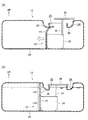
このとき図2(A)に示すように、蓋部28と連結部材18で結合されているポンプモジュール16を所定の位置に移動させる場合を考えると、図中白矢印の方向に蓋部28をスライドさせればポンプモジュール16は所定の位置に移動する。
At this time, as shown in FIG. 2A, considering the case where the
しかし液位センサ14は上記のように満タン液位までの液位を検出する必要上、図1のように凸部26よりも高い位置(車体上側)まで延設されている必要がある。このため、図1の位置までポンプモジュール16を移動させれば図2(A)に示すように液位センサ14が凸部26に干渉する。
However, since the
このとき、例えば図7、図8に示す比較例のように液位センサ114が金属や硬質プラスチックなどの剛体で板状に形成されている場合、液位センサ114の上端が凸部126に干渉することで上記の組み付け作業に支障を来す虞がある。すなわち液位センサ114が凸部126の下を潜り抜けることができず、所定の位置に液位センサ114を設置できない虞がある。
At this time, when the
これに対して本実施形態の液位センサ14は、可撓性のある素材で形成されており、その車体下側部分が固定部分14Aとしてポンプモジュール16の外周面に沿う形で保持されている。一方、液位センサ14におけるポンプモジュール16よりも車体上側に突出した部分は、可動部分14Bとして液位センサ14の可撓性によって弾性変形可能とされている。
On the other hand, the
これにより、図2(A)に示されているように、蓋部28と連結部材18で結合されているポンプモジュール16を所定の位置に移動させる組み付け作業の際、液位センサ14の車体上側端が凸部26に干渉したとしても、ポンプモジュール16と接合されていない部分、すなわちポンプモジュール16より車体上側に突出した部分である可動部分14Bは、上記のように弾性変形可能であるため、図2(B)に示すように液位センサ14が撓んで凸部26の車体下側を潜り抜けることでクリアし、組み付け作業を行うことができる。したがって、本燃料タンク構造では、蓋部28が挿入口28を閉塞する位置まで該蓋部28を移動させると、ポンプモジュール28及び液位センサ14がそれぞれ所定の位置に設置される。
As a result, as shown in FIG. 2 (A), when the
さらに、液位センサ14はポンプモジュール16の外周面に沿った形状に曲げられている。すなわち図3に示すように、ポンプモジュール16の外周面が半径Rの略円筒であった場合は、これに沿って液位センサ14もまた車体上下方向から見た平面図において半径Rの円弧状の断面をもつ円筒形の一部とされる。
Further, the
これにより液位センサ14は可動部分14Bの強度、剛性を維持することができる。すなわち、可動部分14Bの車体上下方向長さ(センサオフセット量)と、図3に示す液位センサ14の幅dに応じて半径Rを設定することで、コーナリング時などに生じる燃料タンク10の内部での燃料の揺動に耐えて、車体上下方向に直立した姿勢を保ち、液位を正しく検出することができる。
As a result, the
すなわち、センサオフセット量が大きくなった場合は半径R(=曲率半径)を小さくすることで液位センサ14の剛性を高くし、燃料の揺動に耐えるようにすることができる。同様に、幅dが大きい形状とする場合にも半径Rを小さくすることで液位センサ14の剛性を高くし、燃料の揺動に耐えるようにすることができる。
That is, when the sensor offset amount increases, the radius R (= curvature radius) is decreased to increase the rigidity of the
液位センサ14の固定に関しては、ポンプモジュール16の外周面に接着する方法以外にも、例えば図6に示すように液位センサ14の車体下側端を把持する把持部17Aと幅方向両端を把持する把持部17Bとをポンプモジュール16の外周面に設け、液位センサ14を嵌め込むことでポンプモジュール16の外周面に固定する構成としてもよい。
Regarding the fixing of the
<第2実施形態> Second Embodiment
次に、本発明の第2実施形態に係る燃料タンク構造について、図5に従って説明する。なお、第1実施形態と同一部材は、同一符号を付してその説明を省略する。 Next, a fuel tank structure according to a second embodiment of the present invention will be described with reference to FIG. In addition, the same member as 1st Embodiment attaches | subjects the same code | symbol, and abbreviate | omits the description.
図5に示すように、本実施形態に係る燃料タンク構造を構成する燃料量計測装置12の液位センサ15は車体上下方向から見た平面図(長手方向に直交する断面視)において角度θで折れ曲がった略V字型の断面をもつ柱状構造とされる。すなわち、液位センサ15は、その長手方向に直交する断面視でV字状を成す第1辺15Aと第2辺15Bとを有して構成されている。
As shown in FIG. 5, the
一方、ポンプモジュール16の外面の一部は、所定の角度θで交わる二平面16A、16Bとされている。そして、液位センサ15は、その第1辺15Aがポンプモジュール16の外面を成す平面16Aに貼り付けなどにより固定され、その第2辺15Bがポンプモジュール16の外面を成す平面16Bに貼り付けなどにより固定されている。
On the other hand, a part of the outer surface of the
以上説明したV字形状においても、第1実施形態と同様に液位センサ15は可動部分の強度を維持することができる。すなわち、ポンプモジュール16の外周面に設けられた2平面と接していない可動部分の車体上下方向長さ(センサオフセット量)と、図5に示す液位センサ15の幅dに応じて角度θを設定することで、コーナリング時などに生じる燃料タンク10の内部での燃料の揺動に耐えて、車体上下方向に直立した姿勢を保ち、液位を正しく検出することができる。
Even in the V-shape described above, the
本実施形態においては、第1実施形態とは異なり液位センサ15の車体上下方向から見た平面図における断面が円弧状ではなく略V字型である。また、ポンプモジュール16の外周面が全体としては例えば図5に示すような略円筒形状であり、液位センサ15はポンプモジュール16の外周面に当該V字形状に沿って設けられた二平面16A、16Bのみでポンプモジュール16に当接する。
In the present embodiment, unlike the first embodiment, the cross section in the plan view of the
これにより本実施形態は液位センサ15の固定(接着、ネジ止めなど)が容易になる、幅d方向のセンター位置合わせが精度よく行えるなどの他に、例えば角度θで交わる直線状のスリット2本でも車体下側端を固定できるなどの特徴を備える。
As a result, in this embodiment, the
また、本実施形態においても可動部分の車体上下方向長さ(センサオフセット量)と、図5に示す液位センサ15の幅dに応じて角度θを設定することで、コーナリング時などに生じる燃料タンク10の内部での燃料の揺動に耐えて液位センサ15が車体上下方向に直立した姿勢を保ち、液位を正しく検出することができる。
Also in this embodiment, the fuel generated at the time of cornering or the like is set by setting the angle θ according to the length of the movable part in the vehicle body vertical direction (sensor offset amount) and the width d of the
すなわち、センサオフセット量が大きくなった場合は角度θ(=Vはさみ角)を小さくすることで液位センサ15の剛性を高くし、燃料の揺動に耐えるようにすることができる。同様に、幅dが大きい形状とする差異にも角度θを小さくすることで液位センサ15の剛性を高くし、燃料の揺動に耐えるようにすることができる。
That is, when the sensor offset amount increases, the angle θ (= V scissor angle) is decreased to increase the rigidity of the
以上、実施形態を挙げて本発明の実施の形態を説明したが、これらの実施形態は一例であり、要旨を逸脱しない範囲内で種々変更して実施できる。例えば液位センサ15は、その第1辺15A及び15Bが、ポンプモジュール16の図3に示すような円筒形状の外周面に固定される構成であっても良い。また例えば、ポンプモジュール16は燃料タンク10の底に配置される構成には限られない。
The embodiments of the present invention have been described above with reference to the embodiments. However, these embodiments are merely examples, and various modifications can be made without departing from the scope of the invention. For example, the
また、本発明の権利範囲がこれらの実施形態に限定されず、本発明の要旨を逸脱しない範囲において種々なる態様で実施し得ることは言うまでもない。 Further, it goes without saying that the scope of rights of the present invention is not limited to these embodiments and can be implemented in various modes without departing from the gist of the present invention.
10 燃料タンク
12 燃料量計測装置
14 液位センサ
14A 固定部分
14B 可動部分
15 液位センサ
15A 第1辺
15B 第2辺
16 ポンプモジュール
17 把持部
18 連結部材
20 外壁
22 挿入口
24 凹部
26 凸部
28 蓋部
120 螺子蓋
F 液面
R 半径
θ 角度
DESCRIPTION OF
Claims (4)
前記燃料タンク内に設置されたポンプモジュールと、
シート状の可撓性素材から成り、車体上下方向に長手となるように配置されると共に長手方向に直交する断面が湾曲又は屈曲形状とされ、車体上側端が前記凸部の車体下側端よりも車体上側に位置されるように車体下端側において前記ポンプモジュールに固定された液位センサと、
を備えた燃料タンク構造。 A fuel tank provided in a vehicle and provided with an insertion port provided on an upper side surface of the vehicle body, and a convex portion protruding around the insertion port on the vehicle body lower side,
A pump module installed in the fuel tank;
It is made of a sheet-like flexible material, and is arranged so as to be longitudinal in the vertical direction of the vehicle body. The cross section orthogonal to the longitudinal direction is curved or bent, and the upper end of the vehicle body is lower than the lower end of the vehicle body of the convex portion. A liquid level sensor fixed to the pump module on the lower end side of the vehicle body so as to be positioned on the upper side of the vehicle body,
With fuel tank structure.
前記液位センサは、円筒形状の前記外周面に密着して固定されている請求項1に記載の燃料タンク構造。 The pump module has a cylindrical shape at least a part of the outer peripheral surface when viewed from the vertical direction of the vehicle body,
The fuel tank structure according to claim 1, wherein the liquid level sensor is fixed in close contact with the cylindrical outer peripheral surface.
Priority Applications (1)
| Application Number | Priority Date | Filing Date | Title |
|---|---|---|---|
| JP2011255448A JP5626187B2 (en) | 2010-12-16 | 2011-11-22 | Fuel tank structure |
Applications Claiming Priority (3)
| Application Number | Priority Date | Filing Date | Title |
|---|---|---|---|
| JP2010280789 | 2010-12-16 | ||
| JP2010280789 | 2010-12-16 | ||
| JP2011255448A JP5626187B2 (en) | 2010-12-16 | 2011-11-22 | Fuel tank structure |
Publications (2)
| Publication Number | Publication Date |
|---|---|
| JP2012141290A true JP2012141290A (en) | 2012-07-26 |
| JP5626187B2 JP5626187B2 (en) | 2014-11-19 |
Family
ID=46677703
Family Applications (1)
| Application Number | Title | Priority Date | Filing Date |
|---|---|---|---|
| JP2011255448A Active JP5626187B2 (en) | 2010-12-16 | 2011-11-22 | Fuel tank structure |
Country Status (1)
| Country | Link |
|---|---|
| JP (1) | JP5626187B2 (en) |
Citations (11)
| Publication number | Priority date | Publication date | Assignee | Title |
|---|---|---|---|---|
| JPS5354670U (en) * | 1976-10-13 | 1978-05-10 | ||
| JPS5784431U (en) * | 1980-11-13 | 1982-05-25 | ||
| JPS6150224U (en) * | 1985-09-12 | 1986-04-04 | ||
| JPH0287022A (en) * | 1988-09-24 | 1990-03-27 | Nippon Denso Co Ltd | Apparatus for measuring liquid level |
| JPH02251722A (en) * | 1989-03-27 | 1990-10-09 | Toshiba Corp | Water level sensor |
| JPH04258725A (en) * | 1991-02-13 | 1992-09-14 | Ngk Spark Plug Co Ltd | Electrostatic capacity type level sensor |
| JPH0755537A (en) * | 1993-02-01 | 1995-03-03 | Lee Maatuk Eng Inc | Probe device for detecting fluctuating fluid level and inclination |
| JPH0921677A (en) * | 1995-07-04 | 1997-01-21 | Suzuki Motor Corp | Liquid level sensor and liquid level detector |
| JP2006189343A (en) * | 2005-01-06 | 2006-07-20 | Denso Corp | Liquid level detector |
| JP2007303982A (en) * | 2006-05-12 | 2007-11-22 | Kougi Kenkyusho:Kk | Sensor device |
| JP3162032U (en) * | 2010-06-07 | 2010-08-19 | 亀岡電子株式会社 | Capacitive liquid level sensor |
-
2011
- 2011-11-22 JP JP2011255448A patent/JP5626187B2/en active Active
Patent Citations (11)
| Publication number | Priority date | Publication date | Assignee | Title |
|---|---|---|---|---|
| JPS5354670U (en) * | 1976-10-13 | 1978-05-10 | ||
| JPS5784431U (en) * | 1980-11-13 | 1982-05-25 | ||
| JPS6150224U (en) * | 1985-09-12 | 1986-04-04 | ||
| JPH0287022A (en) * | 1988-09-24 | 1990-03-27 | Nippon Denso Co Ltd | Apparatus for measuring liquid level |
| JPH02251722A (en) * | 1989-03-27 | 1990-10-09 | Toshiba Corp | Water level sensor |
| JPH04258725A (en) * | 1991-02-13 | 1992-09-14 | Ngk Spark Plug Co Ltd | Electrostatic capacity type level sensor |
| JPH0755537A (en) * | 1993-02-01 | 1995-03-03 | Lee Maatuk Eng Inc | Probe device for detecting fluctuating fluid level and inclination |
| JPH0921677A (en) * | 1995-07-04 | 1997-01-21 | Suzuki Motor Corp | Liquid level sensor and liquid level detector |
| JP2006189343A (en) * | 2005-01-06 | 2006-07-20 | Denso Corp | Liquid level detector |
| JP2007303982A (en) * | 2006-05-12 | 2007-11-22 | Kougi Kenkyusho:Kk | Sensor device |
| JP3162032U (en) * | 2010-06-07 | 2010-08-19 | 亀岡電子株式会社 | Capacitive liquid level sensor |
Also Published As
| Publication number | Publication date |
|---|---|
| JP5626187B2 (en) | 2014-11-19 |
Similar Documents
| Publication | Publication Date | Title |
|---|---|---|
| US9677926B2 (en) | Liquid-level detection device | |
| CN111902961B (en) | Power storage module | |
| JP2012225790A (en) | Liquid level detector | |
| WO2014196194A1 (en) | Liquid level detector | |
| US9645005B2 (en) | Liquid level detector | |
| CN108368802B (en) | Tank cover unit and fuel supply device | |
| JP5807811B2 (en) | Temperature sensor device | |
| JP5626187B2 (en) | Fuel tank structure | |
| US9222604B2 (en) | Seal device for conduit in a fuel dispensing unit | |
| JP2007242681A (en) | Case for containing electronic component | |
| JP5821693B2 (en) | Liquid level detection module and fixing member used for liquid level detection module | |
| JP2017090205A (en) | Liquid level detector | |
| US11742154B2 (en) | Electricity storage module and electricity storage unit | |
| JP2020128966A (en) | Liquid level detector unit | |
| JP5626186B2 (en) | Fuel tank structure | |
| JP4626184B2 (en) | Lead acid battery | |
| JP2007285787A (en) | Liquid condition detection sensor | |
| CN104023497A (en) | Electronic control unit for vehicle | |
| JP2007240183A (en) | Liquid state detecting sensor | |
| CN214412128U (en) | Apparatus and grommet for aligning cables | |
| JP2012220220A (en) | Liquid level detection device | |
| JP7256925B2 (en) | Protective structure of fuel pump connection | |
| US11566945B2 (en) | Fastening device | |
| JP6510281B2 (en) | Fuel supply system | |
| JP5609756B2 (en) | Liquid level detector |
Legal Events
| Date | Code | Title | Description |
|---|---|---|---|
| A621 | Written request for application examination |
Free format text: JAPANESE INTERMEDIATE CODE: A621 Effective date: 20140117 |
|
| A977 | Report on retrieval |
Free format text: JAPANESE INTERMEDIATE CODE: A971007 Effective date: 20140807 |
|
| TRDD | Decision of grant or rejection written | ||
| A01 | Written decision to grant a patent or to grant a registration (utility model) |
Free format text: JAPANESE INTERMEDIATE CODE: A01 Effective date: 20140902 |
|
| A61 | First payment of annual fees (during grant procedure) |
Free format text: JAPANESE INTERMEDIATE CODE: A61 Effective date: 20140915 |
|
| R151 | Written notification of patent or utility model registration |
Ref document number: 5626187 Country of ref document: JP Free format text: JAPANESE INTERMEDIATE CODE: R151 |