JP2012140861A - Lid for underground structure - Google Patents
Lid for underground structure Download PDFInfo
- Publication number
- JP2012140861A JP2012140861A JP2012102172A JP2012102172A JP2012140861A JP 2012140861 A JP2012140861 A JP 2012140861A JP 2012102172 A JP2012102172 A JP 2012102172A JP 2012102172 A JP2012102172 A JP 2012102172A JP 2012140861 A JP2012140861 A JP 2012140861A
- Authority
- JP
- Japan
- Prior art keywords
- motif
- outer peripheral
- noise
- lid
- tire
- Prior art date
- Legal status (The legal status is an assumption and is not a legal conclusion. Google has not performed a legal analysis and makes no representation as to the accuracy of the status listed.)
- Pending
Links
Images


Landscapes
- Underground Structures, Protecting, Testing And Restoring Foundations (AREA)
Abstract
Description
この発明は地下構造物用蓋に関し、例えば、地下構造物用蓋はマンホール用蓋として使用されるものである。 The present invention relates to a cover for an underground structure. For example, the cover for an underground structure is used as a cover for a manhole.
従来のマンホール用蓋90は、図6に示すように、その表面にモチーフ部91,91,…を突設し、その先端面を連続的な平面にして図柄・マーク等を表現していた。
As shown in FIG. 6, a conventional manhole cover 90 has
しかしながら、このモチーフ部は先端面が広いため、車両がマンホール蓋の表面を走行する場合に、タイヤのトレッドパターン内に空気が閉じ込められて圧縮されやすく、この結果、この空気が開放されるときに膨張してノイズが発生しやすく、車両による騒音公害を起こしやすいという不都合を有した。 However, since this motif portion has a wide front end surface, when the vehicle travels on the surface of the manhole cover, air is trapped in the tire tread pattern and easily compressed, and as a result, when this air is released. It has the inconvenience that it is easy to generate noise due to expansion and noise pollution by vehicles.
この発明の課題はこの不都合を解消することである。 An object of the present invention is to eliminate this inconvenience.
この課題を達成するために、発明者は鋭意研究し、この発明を完成した。
この発明に係る地下構造物用蓋においては、円盤体の表面に外周縁に沿って外周凸条を形成するとともにこの外周凸条の内側にモチーフ部を突設形成した地下構造物用蓋において、前記モチーフ部をモチーフの連続性を維持しながら断続的なモチーフ構成部材を連続させることにより構成し、前記円盤体の表面における前記モチーフ部以外の部分に前記モチーフ構成部材よりも小さい小突起を形成し、且つ、前記外周凸条に外周まで開放した溝を多数形成したものである。
In order to achieve this object, the inventors have intensively studied and completed this invention.
In the lid for an underground structure according to the present invention, in the lid for an underground structure in which the outer peripheral ridge is formed along the outer peripheral edge on the surface of the disc body, and the motif portion is formed to project inside the outer peripheral ridge, The motif part is constructed by continuing intermittent motif constituent members while maintaining the continuity of the motif, and small protrusions smaller than the motif constituent members are formed on the surface of the disc body other than the motif part. And many groove | channels open | released to the outer periphery are formed in the said outer periphery protruding item | line.
この場合、前記蓋体の表面における前記モチーフ部以外の部分に前記モチーフ部構成部材よりも小さな小突起を形成することもできる。 In this case, a small protrusion smaller than the motif part constituent member can be formed in a part other than the motif part on the surface of the lid.
また、前記蓋体の表面の外周縁に沿って外周凸条を一体成形するとともにこの外周凸条の内周面を傾斜面とすると共に、前記外周凸条の天面と前記傾斜面の傾斜角を95〜145°にし、且つ、前記傾斜面を波形にすることもできる。 Further, the outer peripheral ridge is integrally formed along the outer peripheral edge of the surface of the lid, and the inner peripheral surface of the outer peripheral ridge is an inclined surface, and the inclination angle between the top surface of the outer peripheral ridge and the inclined surface Can be 95 to 145 °, and the inclined surface can be corrugated.
なお、この場合、前記外周凸条に水抜き溝を設けることもできる。 In this case, a water draining groove can be provided on the outer peripheral ridge.
この発明に係る地下構造物用蓋は上記のように構成されているため、即ち、円盤体の表面に外周縁に沿って外周凸条を形成するとともにこの外周凸条の内側にモチーフ部を突設形成した地下構造物用蓋において、前記モチーフ部をモチーフの連続性を維持しながら断続的なモチーフ構成部材を連続させることにより構成し、前記円盤体の表面における前記モチーフ部以外の部分に前記モチーフ構成部材よりも小さい小突起を形成し、且つ、前記外周凸条に外周まで開放した溝を多数形成したため、このモチーフ部の先端面が狭くなる結果、車両がマンホール蓋の表面を走行する場合に、タイヤのトレッドパターン内に空気が閉じ込められて圧縮されにくくなる。 Since the lid for an underground structure according to the present invention is configured as described above, that is, the outer peripheral ridge is formed along the outer peripheral edge on the surface of the disc body, and the motif portion protrudes inside the outer peripheral ridge. In the formed underground structure lid, the motif portion is configured by continuing intermittent motif constituent members while maintaining the continuity of the motif, and the portion other than the motif portion on the surface of the disc body When the vehicle runs on the surface of the manhole cover as a result of narrowing of the tip surface of this motif part because a small protrusion smaller than the motif component is formed and many grooves that are open to the outer periphery are formed in the outer peripheral ridge In addition, air is trapped in the tire tread pattern, making it difficult to compress.
よって、この地下構造物用蓋を使用すれば、従来発生した、タイヤのトレッドパターン内に閉じ込められた圧縮空気の膨張に基づくノイズの発生は低下するため、従来よりもノイズの発生を減少させることができ、車両による騒音公害を抑制することができる。 Therefore, if this underground structure lid is used, the generation of noise based on the expansion of compressed air confined in the tread pattern of the tire, which has been generated in the past, is reduced. And noise pollution by the vehicle can be suppressed.
なお、前記蓋体の表面における前記モチーフ部以外の部分に前記モチーフ部構成部材よりも小さな小突起を形成すれば、ノイズの軽減の他に相乗的に走行する車両のスリップを防止することができる。 Note that if a small protrusion smaller than the motif component member is formed in a portion other than the motif portion on the surface of the lid, it is possible to prevent slippage of the vehicle traveling synergistically in addition to noise reduction. .
また、前記蓋体の表面の外周縁に沿って外周凸条を一体成形するとともにこの外周凸条の内周面を傾斜面とすると共に、前記外周凸条の天面と前記傾斜面の傾斜角を95〜145°にし、且つ、前記傾斜面を波形にしたため、前記外周凸条内の空気や水が外に排出される結果、ノイズを削減させることができる。また、タイヤの移動がスムーズになるためノイズも減少される。 Further, the outer peripheral ridge is integrally formed along the outer peripheral edge of the surface of the lid, and the inner peripheral surface of the outer peripheral ridge is an inclined surface, and the inclination angle between the top surface of the outer peripheral ridge and the inclined surface The angle is set to 95 to 145 ° and the inclined surface is corrugated, so that air and water in the outer peripheral ridge are discharged to the outside, and noise can be reduced. In addition, since the tire moves smoothly, noise is reduced.
また、この発明に係る地下構造物用蓋は、前記外周凸条の天面と前記傾斜面の傾斜角を95〜145°にしたため、図5に示すように、騒音デシベルが従来より0.5〜3デシベル削減させることができる。この数値限定の根拠は、前記傾斜面の角度を145°より大きくするとタイヤとの摩擦が大きくなってノイズが大きくなり、また、95°未満にすると傾斜面の根幹部とタイヤの表面との間に空気が封入されて大きなノイズが発生するからである。 Moreover, since the lid | cover for underground structures which concerns on this invention made the inclination | tilt angle of the top | upper surface of the said outer periphery protruding item | line and the said inclined surface into 95-145 degrees, as shown in FIG. It can be reduced by ~ 3dB. The reason for this numerical limitation is that if the angle of the inclined surface is greater than 145 °, the friction with the tire increases and noise increases, and if it is less than 95 °, there is a gap between the root of the inclined surface and the tire surface. This is because a large noise is generated when air is sealed in.
よって、この地下構造物用蓋を使用すれば、従来発生した、タイヤのトレッドパターン内に閉じ込められた圧縮空気の膨張に基づくノイズの発生は低下するため、従来よりもノイズの発生を減少させることができ、車両による騒音公害を抑制することができる。 Therefore, if this underground structure lid is used, the generation of noise based on the expansion of compressed air confined in the tread pattern of the tire, which has been generated in the past, is reduced. And noise pollution by the vehicle can be suppressed.
なお、この場合、前記外周凸条に水抜き溝を設ければ、デザイン面の凹部に溜まる水や空気を舗装面の方に排出しやすくすることができる。 In this case, if a drainage groove is provided in the outer peripheral ridge, it is possible to easily discharge water or air accumulated in the concave portion of the design surface toward the pavement surface.
モチーフの連続性を維持しながら断続的にモチーフ部を構成するには、そのモチーフ部構成部材の一構成単位は、幅5〜25mmで長さが30〜150mm位が適している。 In order to intermittently constitute the motif part while maintaining the continuity of the motif, it is suitable that one constituent unit of the motif part constituting member has a width of 5 to 25 mm and a length of about 30 to 150 mm.
前記突条部材の天面と前記傾斜面の角度を 95〜145°にすれば、図5に示すように、騒音デシベルが従来より0.5〜3ノイズを削減させることができる。 If the angle between the top surface of the ridge member and the inclined surface is 95 to 145 °, as shown in FIG. 5, the noise decibel can be reduced by 0.5 to 3 noise from the conventional level.
オクターブバンド分析は、各周波数帯域別の音圧レベルを求めて評価する方法である。リヤルタイムアナライザー分析は、瞬時の音圧レベルを評価する方法である。FFTアナライザー分析は、狭帯域での卓越した騒音の有無を確認する方法で、他のノイズの有無を計測する方法であり、この技術を地下構造物用蓋ノイズの性能分析に取り入れた。 Octave band analysis is a method of obtaining and evaluating sound pressure levels for each frequency band. Real time analyzer analysis is a method for evaluating the instantaneous sound pressure level. The FFT analyzer analysis is a method of confirming the presence or absence of excellent noise in a narrow band, and measuring the presence or absence of other noise. This technology was incorporated into the performance analysis of lid noise for underground structures.
以下、この発明の実施例を説明する。 Examples of the present invention will be described below.
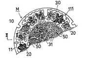
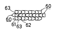
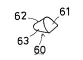
図1はこの発明に係る地下構造物用蓋の平面図、図2は図1におけるII−II線拡大断面図、図3は図1における小突起の他の実施例の部分平面図、図4は同斜視図,図5は突条部材の傾斜角θと騒音デシベルとの関係を示したグラフである。 1 is a plan view of a cover for an underground structure according to the present invention, FIG. 2 is an enlarged sectional view taken along line II-II in FIG. 1, FIG. 3 is a partial plan view of another embodiment of the small protrusion in FIG. Is a perspective view, and FIG. 5 is a graph showing the relationship between the inclination angle θ of the ridge member and the noise decibel.
図1および図2において、Mはマンホール用蓋であり、円盤体(本発明の「蓋体」に相当する。)10を主構成部材としている。このマンホール用蓋Mはこの発明の地下構造物用蓋に相当する。 In FIGS. 1 and 2, M is a manhole cover, and a disk body (corresponding to the “lid body” of the present invention) 10 is a main component. The manhole cover M corresponds to the underground structure cover of the present invention.
11は外周凸条(この発明の「突条部材」に相当する)であり、前記円盤体10における表面の外周縁に沿って一体的に突設されている。この外周凸条11は環状であり、マンホール用蓋Mの強度を維持するためのものである。なお、途中に水抜き溝111 が形成されている。
図2に示すように、前記外周凸条11は、内側がスカート状の傾斜面12に形成されている。この外周凸条11の天面と前記傾斜面12の角度θは 95〜145°が適している。95°未満にすると、タイヤの通過時に起こるタイヤの圧縮膨張によりノイズが高まる他空気や溜水の排水がしにくくなる。また、145°以上にすると空気がタイヤの表面の凹部(トレッドパターンの凹部)に圧縮空気として閉じ込められ易く、開放時に圧縮空気の膨張によって発生するノイズが大きくなるとともにタイヤのスリップもしやすくなるためである。
As shown in FIG. 2, the outer
このように、傾斜角θを設定すると、図5に示すように、騒音デシベルが従来より0.5〜3ノイズを削減させることができる。この数値限定の根拠は、前記傾斜面の角度を145°より大きくするとタイヤとの摩擦が大きくなってノイズが大きくなり、また、95°未満にすると傾斜面の根幹部とタイヤの表面との間に空気が封入されて大きなノイズが発生するからである。なお、図5に示すように、前記角度θを110〜145°にすると、削減される騒音デシベルは1〜3dBとなり、その効果は顕著にあらわれる。これらのノイズの測定方法および測定条件(Hz,測定点,車両速度等)は図に記載されている。 Thus, when the inclination angle θ is set, as shown in FIG. 5, the noise decibel can reduce 0.5 to 3 noise compared to the conventional art. The reason for this numerical limitation is that if the angle of the inclined surface is greater than 145 °, the friction with the tire increases and noise increases, and if it is less than 95 °, there is a gap between the root of the inclined surface and the tire surface. This is because a large noise is generated when air is sealed in. As shown in FIG. 5, when the angle θ is set to 110 to 145 °, the noise decibels to be reduced are 1 to 3 dB, and the effect is remarkable. These noise measurement methods and measurement conditions (Hz, measurement points, vehicle speed, etc.) are described in the figure.
なお、図2に仮想線で示すように、前記傾斜面12に湾曲状突条部121 を設ければ、タイヤへの衝撃が少なくなりノイズの発生が低下する。
As shown by phantom lines in FIG. 2, if the
また、図2に仮想線で示すように、前記傾斜面12に湾曲状凹溝部122 を設ければ、上面と傾斜面の角部が鋭角になり、スリップしにくくなる。
In addition, as shown by phantom lines in FIG. 2, if the curved
また、図2に仮想線で示すように、前記傾斜面12の下端を凹曲面状124 にすれば、傾斜面と下端の角部の鋳造成形時の砂落ちが良くなるとともに、製品としても泥がたまりにくくなる。
Further, as shown by phantom lines in FIG. 2, if the lower end of the
なお、前記傾斜面は前記外周凸条11の両側に形成することもできる。
The inclined surfaces can be formed on both sides of the outer
また、この前記外周凸条11の内周面における波形模様12は、空気や水を排出してノイズを削減させる効果と、タイヤの移動がスムーズになる効果がある。また、波形にすることで、平坦部(先端面の)の面積を少なくしてタイヤの摩擦騒音の発生を少なくすることができる。さらに、前記外周凸条11に外周まで解放した溝111 を多数形成して、デザイン面の凹部に溜まる水や空気を舗装面の方に排出しやすくすることができる。なお、この場合、溝幅を5〜25mmにすることによって舗装面側に排水し易いものである。
Further, the
20は環状モチーフ部(この発明の「突条部材」に相当する)であり、前記外周凸条11の内側に形成されている。この環状モチーフ部20は、蝶の図,花の図等がモチーフ化されて円盤体10の表面に一体的に形成されたものである。この環状モチーフ部20の間には市町村等の徽章が突設されるのが常である。なお、この環状モチーフ部20も側面が前記外周凸条11と同じようにスカート状の傾斜面に形成されている。
30は中心モチーフ部(この発明の「突条部材」に相当する)であり、前記円盤体10の中心部に一体的に形成されている。この中心モチーフ部30は、当該モチーフ部の連続性、即ち、海原に船が帆走している図の状態、を維持しながら断続的なモチーフ構成部材31,31,…を連続させることによって構成されている。このモチーフ構成部材31の大きさは、タイヤとの摩擦を断続し、ノイズを軽減させることから、幅5〜25mmで長さが30〜150mm位が適している。
幅を5〜25mmに限定した理由は、タイヤのトレッドパターンの幅との組み合わせで選定した。また、同長さが30〜150mm位が適しているのは、タイヤの設置幅が200mm程度であることからこの幅との組み合わせで選定した。 The reason for limiting the width to 5 to 25 mm was selected in combination with the width of the tread pattern of the tire. Further, the reason why the length of about 30 to 150 mm is suitable is selected in combination with this width because the installation width of the tire is about 200 mm.
表1〜4にこの実施例のノイズの測定結果を示したが、いずれの場合にも、従来例に比べノイズは1〜4dB(A) 減少している。特に顕著なのは、1000Hzを中心に概ね500 〜2000Hzであり、3〜4dB(A) の改善が見られる。なお、表中の「測定点」とは、マンホールの表面から測定位置までの高さであり、「速度」とは、走行する車両の速さである。測定方法は、後記するオクターブバンド分析方法を使用した。 Tables 1 to 4 show the noise measurement results of this example. In any case, the noise is reduced by 1 to 4 dB (A) compared to the conventional example. Particularly noticeable is approximately 500 to 2000 Hz centering on 1000 Hz, and an improvement of 3 to 4 dB (A) is observed. The “measurement point” in the table is the height from the surface of the manhole to the measurement position, and the “speed” is the speed of the traveling vehicle. As the measurement method, the octave band analysis method described later was used.
なお、隣り合うモチーフ構成部材31の間隔は、当該モチーフ部の連続性が把握される範囲であれば良い。なお、この中心モチーフ部30も側面が前記外周凸条11と同じようにスカート状の傾斜面に形成されている。
The interval between adjacent motif
次に、50,50,…は小突起であり、前記蓋体10の表面における前記中心モチーフ部30以外の部分に一体形成されている。この小突起50は前記中心モチーフ部のモチーフ構成部材31よりも小さくすることが必要であり、その大きさは、5〜30mm位である。この小突起50は走行する車両のタイヤとの間から発生するノイズを低下させるとともに、車両のスリップを防止するためのものである。
Next, 50, 50,... Are small protrusions that are integrally formed on the surface of the
この小突起50の形状は、側面から見た場合略三角形や二等辺三角形である。この場合、一辺の角度が30〜45°で断面がドーム状になっている。これは、タイヤの設置面積を大きくするためである。また、相対する辺は45〜85°で断崖状のシャープな面となっている。この効果としては、タイヤのスパイク効果となる。
The shape of the
なお、前記小突起50の形状はいかなる形状でも良く、例えば、図3および図4に示すように、三角突起60を円盤体10の表面に形成し、その前面61はそのままの状態で、背面62と両側面63,63 とを湾曲状に曲面として形成することもできる。このような三角突起60を一列毎に逆方向に連続して形成するといずれの方向からの走行(車両の)に対しても磨耗が少なくてスリップしにくい効果がある。また、この三角突起60,60 の間には隙間が存在しているため、タイヤがその三角突起60の上を通過しているときは、タイヤ表面の凹部に圧縮空気が閉じ込められにくくノイズの削減に効果がある。
The
なお、前記小突起50を、デザインモチーフを生かしながら4〜10等分に均等に概略コロニー状に割りつければ、交差点などで、多方面からの車両の進入に対し、ノイズ低減とスリップ防止の効果がある。
If the
また、前記小突起50群は、デザイン面に占める面積は20〜40パーセントが良い。これより少ないとスリップ止めの目的を失い,多いとモチーフが表現できなくなる。
Further, the area of the
次に、円盤体10のデザイン面のノイズをデジタル測定する方法について具体的に説明する。
鉄蓋のデザイン面上を自動車を通過させて、蓋体から発生するノイズをオクターブバンド分析、リヤルタイムアナライザー分析,FFTアナライザー分析等によって、デジタル化し、舗装道路面の相応する値との差を見て判断する。路面と鉄蓋面との通過騒音差が小さければ小さいほどノイズの発生は少ないものと判断される。
Next, a method for digitally measuring the noise on the design surface of the
The car is passed over the design of the iron lid, and the noise generated from the lid is digitized by octave band analysis, real time analyzer analysis, FFT analyzer analysis, etc., and the difference from the corresponding value on the paved road surface is observed. Judgment. It is determined that the smaller the difference in passing noise between the road surface and the iron cover surface is, the less noise is generated.
マンホールの蓋として、モチーフ部の表現を維持した状態で、タイヤのトレッドパターン内に閉じ込められた圧縮空気の膨張に基づくノイズの発生を減少させることができ、車両による騒音公害を抑制することができる。 As a manhole cover, with the expression of the motif part maintained, noise generation based on the expansion of compressed air confined in the tread pattern of the tire can be reduced, and noise pollution by the vehicle can be suppressed. .
M … マンホール用蓋(地下構造物用蓋)
θ … 傾斜角
10 … 円盤体(蓋体)
11 … 外周凸条(突条部材)
111 … 溝
20 … 環状モチーフ部(突条部材)
30 … 中心モチーフ部(突条部材)
31 … モチーフ構成部材
50 … 小突起
60 … 三角突起
61 … 前面(三角突起の)
62 … 背面(三角突起の)
63 … 側面(三角突起の)

θ… Inclination angle
10… Disc body (lid)
11 ... Peripheral ridge (projection member)
111… Groove
20… Annular motif (protrusion member)
30… Center motif (protrusion member)
31… Motif component
50… Small protrusion
60… Triangular protrusion
61… front (triangular)
62… Back (triangular)
63… Side (triangular)
Claims (1)
In the lid for an underground structure in which outer circumferential ridges are formed on the surface of the disk body along the outer peripheral edge and a motif portion is formed protrudingly on the inner side of the outer circumferential ridge, while maintaining the continuity of the motif in the motif portion Consisting of intermittent motif constituent members, forming small protrusions smaller than the motif constituent members on the surface of the disc body other than the motif portion, and opening the outer peripheral ridges to the outer periphery A cover for an underground structure, characterized in that a large number of grooves are formed.
Priority Applications (1)
| Application Number | Priority Date | Filing Date | Title |
|---|---|---|---|
| JP2012102172A JP2012140861A (en) | 2012-04-27 | 2012-04-27 | Lid for underground structure |
Applications Claiming Priority (1)
| Application Number | Priority Date | Filing Date | Title |
|---|---|---|---|
| JP2012102172A JP2012140861A (en) | 2012-04-27 | 2012-04-27 | Lid for underground structure |
Related Parent Applications (1)
| Application Number | Title | Priority Date | Filing Date |
|---|---|---|---|
| JP2010163436A Division JP2010261306A (en) | 2010-07-20 | 2010-07-20 | Lid for underground structure |
Publications (1)
| Publication Number | Publication Date |
|---|---|
| JP2012140861A true JP2012140861A (en) | 2012-07-26 |
Family
ID=46677382
Family Applications (1)
| Application Number | Title | Priority Date | Filing Date |
|---|---|---|---|
| JP2012102172A Pending JP2012140861A (en) | 2012-04-27 | 2012-04-27 | Lid for underground structure |
Country Status (1)
| Country | Link |
|---|---|
| JP (1) | JP2012140861A (en) |
Citations (5)
| Publication number | Priority date | Publication date | Assignee | Title |
|---|---|---|---|---|
| JPS6395751U (en) * | 1986-12-08 | 1988-06-21 | ||
| JPH09235748A (en) * | 1995-12-28 | 1997-09-09 | Hinode Suido Kiki Kk | Cover for subsurface structure and cover body and receiving frame thereof |
| JPH10131225A (en) * | 1995-12-28 | 1998-05-19 | Hinode Suido Kiki Kk | Cover main body of cover for underground structure |
| JP2001032310A (en) * | 1999-07-22 | 2001-02-06 | Nippon Chutetsukan Kk | Iron cover |
| JP2003313894A (en) * | 2002-04-24 | 2003-11-06 | Suzuki Chutetsu Kogyo Kk | Manhole cover |
-
2012
- 2012-04-27 JP JP2012102172A patent/JP2012140861A/en active Pending
Patent Citations (5)
| Publication number | Priority date | Publication date | Assignee | Title |
|---|---|---|---|---|
| JPS6395751U (en) * | 1986-12-08 | 1988-06-21 | ||
| JPH09235748A (en) * | 1995-12-28 | 1997-09-09 | Hinode Suido Kiki Kk | Cover for subsurface structure and cover body and receiving frame thereof |
| JPH10131225A (en) * | 1995-12-28 | 1998-05-19 | Hinode Suido Kiki Kk | Cover main body of cover for underground structure |
| JP2001032310A (en) * | 1999-07-22 | 2001-02-06 | Nippon Chutetsukan Kk | Iron cover |
| JP2003313894A (en) * | 2002-04-24 | 2003-11-06 | Suzuki Chutetsu Kogyo Kk | Manhole cover |
Similar Documents
| Publication | Publication Date | Title |
|---|---|---|
| JP2006341655A (en) | Pneumatic tire | |
| WO2009084666A1 (en) | Tire | |
| JP2006069305A (en) | Pneumatic tire | |
| JP2008296795A (en) | Pneumatic tire | |
| EA018685B1 (en) | Tread with incisions | |
| KR20150138435A (en) | Pneumatic tire | |
| JP4958361B2 (en) | Tire tread pattern | |
| JP2021187436A (en) | Pneumatic tire with application of 3d calf | |
| JP4732379B2 (en) | Pneumatic tire | |
| US20140130948A1 (en) | Tyre provided with sound channels | |
| JP2878663B2 (en) | Lid for underground structures | |
| JPH10250317A (en) | Heavy duty pneumatic tire | |
| JP2006225994A (en) | Lid for underground structure and method of evaluating the same | |
| JP4812039B2 (en) | Pneumatic tire | |
| JPH01223006A (en) | Structure of tread portion of pneumatic tyre | |
| JP2012140861A (en) | Lid for underground structure | |
| JP2010261306A (en) | Lid for underground structure | |
| JP4600027B2 (en) | Pneumatic tire | |
| KR20170116777A (en) | Tread Kerf of Heavy Vehicle Tire | |
| JP5551137B2 (en) | Pneumatic tire | |
| CN108430805B (en) | Pneumatic tire for vehicle | |
| KR20160017179A (en) | Kerf structure and pneumatic tire comprising the same | |
| KR101878324B1 (en) | Medium long distance guide wheel tyre pattern | |
| JP4457735B2 (en) | Pneumatic tire | |
| JP2601560Y2 (en) | Pneumatic tire |
Legal Events
| Date | Code | Title | Description |
|---|---|---|---|
| A621 | Written request for application examination |
Free format text: JAPANESE INTERMEDIATE CODE: A621 Effective date: 20120427 |
|
| A977 | Report on retrieval |
Free format text: JAPANESE INTERMEDIATE CODE: A971007 Effective date: 20130308 |
|
| A131 | Notification of reasons for refusal |
Free format text: JAPANESE INTERMEDIATE CODE: A131 Effective date: 20130318 |
|
| A521 | Written amendment |
Free format text: JAPANESE INTERMEDIATE CODE: A523 Effective date: 20130517 |
|
| A02 | Decision of refusal |
Free format text: JAPANESE INTERMEDIATE CODE: A02 Effective date: 20130805 |