JP2012139952A - Label forming device and control method for label forming device - Google Patents
Label forming device and control method for label forming device Download PDFInfo
- Publication number
- JP2012139952A JP2012139952A JP2011000502A JP2011000502A JP2012139952A JP 2012139952 A JP2012139952 A JP 2012139952A JP 2011000502 A JP2011000502 A JP 2011000502A JP 2011000502 A JP2011000502 A JP 2011000502A JP 2012139952 A JP2012139952 A JP 2012139952A
- Authority
- JP
- Japan
- Prior art keywords
- label
- cut
- tape
- mark
- image
- Prior art date
- Legal status (The legal status is an assumption and is not a legal conclusion. Google has not performed a legal analysis and makes no representation as to the accuracy of the status listed.)
- Pending
Links
Images


Abstract
Description
本発明は、テープ状部材にラベル画像を印刷してラベルを作成するラベル作成装置およびラベル作成装置の制御方法に関する。 The present invention relates to a label producing apparatus for producing a label by printing a label image on a tape-like member, and a control method for the label producing apparatus.
従来、この種の装置は、印刷画像の前端から連続する空白部分(前端から印字開始位置まで)の長さがヘッド−カッタ間の長さよりも短い場合や、ラベル画像を複数個連続して印刷する場合に、テープ状部材にカット位置を示すカットマークを印刷する(例えば、特許文献1参照)。この場合、ユーザーが、カットマークを指標としてテープ状部材を手動切断することにより、ラベルを形成する実領域と余白やその他のラベルとなる不要領域とが分離され、所望のラベルが作成される。 Conventionally, this type of apparatus prints a plurality of label images continuously when the length of a blank portion (from the front end to the print start position) continuous from the front end of the print image is shorter than the length between the head and the cutter. When doing so, the cut mark which shows a cutting position is printed on a tape-shaped member (for example, refer to patent documents 1). In this case, the user manually cuts the tape-shaped member using the cut mark as an index, so that the actual area for forming the label and the unnecessary area that becomes the margin and other labels are separated, and a desired label is created.
ところで、特許文献1に記載のテープ印刷装置は、カットマークとして、テープ状部材の幅方向に2個の点状画像を並べて印刷する。しかし、カットマークをこのような点や線で構成すると、ユーザーがこの点や線を印字汚れ等と誤認してしまう虞れがある。このように、ユーザーがカットマークを認識できない場合、テープ状部材が適切な位置でカットされずに所望のラベルを作成することができないという問題があった。 By the way, the tape printer described in Patent Document 1 prints two dot images side by side in the width direction of the tape-shaped member as cut marks. However, if the cut mark is composed of such points and lines, there is a possibility that the user mistakes these points and lines as print stains. As described above, when the user cannot recognize the cut mark, there is a problem that a desired label cannot be created without the tape-shaped member being cut at an appropriate position.
本発明は、上記の点に鑑み、ユーザーに対し適切にカット位置を示すカットマークを印刷することのできるラベル作成装置およびラベル作成装置の制御方法を提供することを課題とする。 In view of the above points, an object of the present invention is to provide a label producing apparatus and a label producing apparatus control method capable of printing a cut mark that appropriately indicates a cut position to a user.
本発明のラベル作成装置は、ラベルの作成後、当該ラベルの実領域と不要領域を分離するために、当該ラベルを幅方向に手動切断する際の指標となるカットマークを印刷可能なラベル作成装置であって、ラベルの長手方向に所定の長さ(但し、長さ0を除く)を有するカットマークの画像データであり、ラベルの不要領域の少なくとも一部として印刷されるマーク画像を記憶するマーク画像記憶部と、ラベルの実領域に印刷されるラベル画像の、長手方向における隣接位置にマーク画像を付加して印刷データを生成する印刷データ生成部と、印刷データをテープ状部材に印刷し、ラベルを作成するラベル作成部と、を備えたことを特徴とする。 The label producing apparatus of the present invention is a label producing apparatus capable of printing a cut mark as an index when manually cutting the label in the width direction in order to separate an actual area and an unnecessary area of the label after producing the label. A mark that is image data of a cut mark having a predetermined length (excluding length 0) in the longitudinal direction of the label, and stores a mark image printed as at least a part of an unnecessary area of the label An image storage unit, a print data generation unit for generating a print data by adding a mark image to an adjacent position in the longitudinal direction of a label image printed in the actual area of the label, and printing the print data on a tape-like member, And a label creating unit for creating a label.
本発明のテープ印刷装置の制御方法によれば、ラベルの作成後、当該ラベルの実領域と不要領域を分離するために、当該ラベルを幅方向に手動切断する際の指標となるカットマークを印刷可能なラベル作成装置の制御方法であって、ラベルの長手方向に所定の長さ(但し、長さ0を除く)を有するカットマークの画像データであり、ラベルの不要領域の少なくとも一部として印刷されるマーク画像を記憶するマーク画像記憶ステップと、ラベルの実領域に印刷されるラベル画像の、長手方向における隣接位置にマーク画像を付加して印刷データを生成する印刷データ生成ステップと、印刷データをテープ状部材に印刷し、ラベルを作成するラベル作成ステップと、を実行することを特徴とする。 According to the control method of the tape printer of the present invention, after a label is created, a cut mark serving as an index for manually cutting the label in the width direction is printed in order to separate the real area and the unnecessary area of the label. A method for controlling a label producing apparatus, which is image data of a cut mark having a predetermined length (excluding length 0) in the longitudinal direction of the label, and is printed as at least a part of an unnecessary area of the label A mark image storing step for storing the mark image to be printed, a print data generating step for generating a print data by adding a mark image to an adjacent position in the longitudinal direction of the label image printed in the actual area of the label, and the print data And a label creating step of creating a label on the tape-like member.
これらの構成によれば、カットマークは、ラベルの長手方向に所定の長さ(但し、長さ0を除く)を有するものであるため、印字汚れ等に誤認されることのない存在感のあるカットマークを印刷することができる。また、カットマークがラベルの不要領域に印刷されるため、ユーザーに対しカットマークを明確に示しつつも、所望のテープ長のラベルを得ることができる。なお、カットマークがテープ状部材の長手方向に幅を持っていることから、マーク上をカットするとカット後に形成されたラベルにマークの一部が残ってしまうことが明白であるため、ユーザーに対してマークのテープ長方向外側をカットするよう促すことができる。よって、カットマークの一部がラベルに残らないため、ラベルの意匠性を損ねることがない。なお、連続して印刷されたラベル画像を分離する場合は、カットマークのテープ長方向における両外側2箇所を切断することになる。 According to these configurations, the cut mark has a predetermined length (excluding length 0) in the longitudinal direction of the label, and thus has a presence that is not mistaken for print stains or the like. Cut marks can be printed. Further, since the cut mark is printed in an unnecessary area of the label, a label having a desired tape length can be obtained while clearly showing the cut mark to the user. In addition, since the cut mark has a width in the longitudinal direction of the tape-shaped member, it is clear that when the mark is cut, a part of the mark remains on the label formed after the cut. To cut the outside of the mark in the tape length direction. Therefore, a part of the cut mark does not remain on the label, so that the design of the label is not impaired. Note that, when separating continuously printed label images, the two outer sides of the cut mark in the tape length direction are cut.
この場合、マーク画像は、長手方向の長さが不要領域として設定され得る最小の領域幅よりも短めに設定され、不要領域の長手方向における端から離れた位置に配置されていることが好ましい。 In this case, it is preferable that the mark image has a length in the longitudinal direction set shorter than a minimum region width that can be set as an unnecessary region, and is arranged at a position away from the end in the longitudinal direction of the unnecessary region.
この構成によれば、カットマークのテープ長方向外側をカットする場合、カット位置がラベルの実領域内に侵入してラベルの長さを短くしてしまうことがない。 According to this configuration, when the outside of the cut mark in the tape length direction is cut, the cut position does not enter the actual area of the label and the length of the label is not shortened.
この場合、カットマークは、カットすべき位置を示すテキスト情報または画像を含むことが好ましい。 In this case, the cut mark preferably includes text information or an image indicating a position to be cut.
この構成によれば、より分かりやすくユーザーにカット位置を示すことができる。なお、カットマークは、カット位置がカットマーク上ではなくカットマークとラベル画像との間であることを示すテキスト情報または画像であることが望ましい。 According to this configuration, the cutting position can be shown to the user in a more easily understandable manner. The cut mark is preferably text information or an image indicating that the cut position is not on the cut mark but between the cut mark and the label image.
この場合、カットマークは、枠画像であることが好ましい。 In this case, the cut mark is preferably a frame image.
さらに、枠画像の枠線は、太枠であることが好ましい。 Furthermore, the frame line of the frame image is preferably a thick frame.
この構成によれば、カット位置が、カットマーク上ではなくカットマークとラベル画像との間であることを、より分かりやすくユーザーに示すことができる。 According to this structure, it can be shown to a user more easily that the cut position is not on the cut mark but between the cut mark and the label image.
この場合、カットマークは、連続印刷される複数のラベル画像の間に設けられることが好ましい。 In this case, the cut mark is preferably provided between a plurality of continuously printed label images.
この構成によれば、1枚印刷だけでなく連続印刷の場合も、印字汚れ等に誤認されることのない存在感のあるカットマークを印刷すると共に、所望のテープ長のラベルを得ることができる。 According to this configuration, in the case of continuous printing as well as single-sheet printing, it is possible to print a cut mark with a presence that is not misidentified as a print stain or the like and to obtain a label with a desired tape length. .
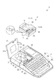
以下、本発明の一実施形態について、添付図面を参照しながら詳細に説明する。図1は、本実施形態に係るテープ印刷装置1の開閉蓋21を開いた状態の外観斜視図である。図示のようにテープ印刷装置1は、装置ケース2により外郭が形成され、装置ケース2の前部上面には各種入力キーを備えたキーボード3が配置されると共に、後部上面には、その左部に開閉蓋21が取り付けられ、その右部には表示画面41が配設されている。
Hereinafter, an embodiment of the present invention will be described in detail with reference to the accompanying drawings. FIG. 1 is an external perspective view of the tape printer 1 according to the present embodiment with the open /
開閉蓋21の内側にはテープカートリッジCを装着するためのカートリッジ装着部6が窪入形成されており、テープカートリッジCは、開閉蓋21を開放した状態でカートリッジ装着部6に着脱可能に装着される。また、開閉蓋21にはこれを閉じた状態でテープカートリッジCの装着/非装着を視認するための覗き窓21aが形成されている。
A cartridge mounting portion 6 for mounting the tape cartridge C is recessed inside the opening /
キーボード3には、文字キー群3a、および各種動作モード等を指定するための機能キー群3bが配列されている。文字キー群3aは、JIS配列に基づいたフルキー構成であり、操作するキー数の増加を抑えるためのシフトキーを備えるなど、一般のワードプロセッサー等と同様である。また、機能キー群3bには、[カーソル]キー、[選択]キー、[削除]キー、[印刷]キー、[連続]キー、[書式設定]キー、および[環境設定]キーなどが含まれる。
On the
[カーソル]キーは、上下左右キー([↑],[↓],[←],[→])から成り、カーソル移動やスクロール操作を行うためのキーである。当該、[カーソル]キーの他、[選択]キーや[削除]キーは、情報入力時および各種設定時に用いられるキーである。[印刷]キーは、印刷の実行を指示するためのキーである。また、[印刷]キーは、上記のシフトキーと同時に押下することで、テープTのカットを指示することができる。なお、この動作は、後述のカット設定の「「自動カットなし」設定においテープTの印刷済み部分を切断する際に使用する。 The [cursor] key is made up of up / down / left / right keys ([↑], [↓], [←], [→]), and is used for cursor movement and scrolling operations. In addition to the [cursor] key, the [select] key and the [delete] key are keys used for information input and various settings. The [Print] key is a key for instructing execution of printing. The [Print] key can be instructed to cut the tape T by being pressed simultaneously with the shift key. This operation is used when cutting a printed portion of the tape T in a later-described cut setting of “No automatic cut”.
[連続]キーは、同一のラベルを、複数枚印刷する連続印刷を行うためのキーである。本実施形態では、当該[連続]キーの押下により、連続印刷の設定を行い得るようになっている。なお、[連続]キーの押下により、数字等の部分だけが異なる複数のラベルを連続して印刷する連番印刷を行う構成としてもよい。 The [Continuous] key is a key for performing continuous printing for printing a plurality of the same labels. In the present embodiment, continuous printing can be set by pressing the [continuous] key. In addition, it is good also as a structure which performs the serial number printing which prints the several label from which only parts, such as a number differ, by pressing the [continuous] key.
[書式設定]キーは、印刷データの編集に関する各種設定を行うためのキーである。本実施形態では、当該[書式設定]キーの押下により、余白設定を行い得るようになっている。余白設定とは、作成する単一のラベルの両端に設ける余白101の長さを決めるものである。すなわち、作成されるラベルは、ユーザーが編集したラベル画像100と、当該ラベル画像100のテープ長方向両端に設けられる余白101と、を合わせた長さとなる(図5参照)。なお、本実施形態の余白設定では、[書式設定]キーの押下操作により、「極少(余白101:1mm)」、「少なめ(余白101:9mm)」、「ふつう(余白101:12mm)」および「多め(余白101:18mm)」のうちのいずれかが選択できるようになっている。そして、このうちの「極少(余白101:1mm)」が選択された場合、テープ印刷装置1は、最初に印刷されるラベル画像100の先端位置に設けられた余白101のさらに先端位置にカットマークCMを印刷する(図4および5参照)。これは、余白101の長さ(1mm)がテープ印刷装置1のカッタ−ヘッド間の距離よりも短いにも拘らず、テープ印刷装置1がテープTの逆送り機能を備えていないため、所望の先端位置で自動カットを行うことができないからである。
The [Format Setting] key is a key for performing various settings relating to editing of print data. In the present embodiment, margin setting can be performed by pressing the [format setting] key. The margin setting determines the length of the
[環境設定]キーは、各種環境設定を行うためのキーである。本実施形態では、当該[環境設定]キーの押下により、カット設定を行い得るようになっている。このカット設定では、ラベルの後端を自動カットする「自動カットあり」と、ラベルの後端を自動カットしない「自動カットなし」のいずれかを選択できるようになっている。「自動カットなし」は、自動カットが不可能なテープ状部材(アイロンラベルやマグネットテープ等)に印刷する場合や、連続印刷において各ラベルを連ねたまま印刷したい場合等に設定する。なお、連続印刷を行う際、「自動カットあり」では、ラベル間カットが自動的に行われ、「自動カットなし」では、ラベル間カットは行われない。なお、「自動カットなし」においてテープ印刷装置1は、カット位置(カットされるべき位置)にカットマークCMを印刷する(図4および5参照)。なお、上記のように「自動カットなし」において、テープTの印刷済み部分の切断は、ユーザーのシフトキーと[印刷]キーを同時に押下することによって行われる。 The “environment setting” key is a key for performing various environment settings. In the present embodiment, the cut setting can be performed by pressing the [environment setting] key. In this cut setting, either “automatic cut” that automatically cuts the rear end of the label or “no automatic cut” that does not automatically cut the rear end of the label can be selected. “No automatic cutting” is set when printing on a tape-like member (such as an iron label or a magnetic tape) that cannot be automatically cut, or when it is desired to print with each label being continuous in continuous printing. When continuous printing is performed, the “cutting between labels” is automatically performed when “with automatic cutting”, and the cutting between labels is not performed when “without automatic cutting”. Note that the tape printing apparatus 1 prints the cut mark CM at the cut position (position to be cut) in “without automatic cut” (see FIGS. 4 and 5). As described above, in “no automatic cut”, the printed portion of the tape T is cut by simultaneously pressing the user's shift key and [print] key.
表示画面41は、液晶ディスプレーであり、ユーザーがキーボード3を用いて入力した入力情報に基づく編集結果、および当該編集結果に基づいて生成された印刷データ等を確認したりする際に用いられる。なお、上記の各種設定に応じて印刷データにカットマークCMが含まれる場合、表示画面41に当該カットマークCMは表示されず、ラベル画像100および余白101のみが表示される。また、表示画面41には、後述のテープ識別センサー27によりテープカートリッジCに収容されているテープTが切断不能と判別されたにもかかわらず、カット設定が「自動カットあり」となっていた場合、エラー表示される。また、「自動カットなし」でのすべての印刷が終了した場合、シフトキーおよび[印刷]キーの同時押下による切断を指示する旨のメッセージを表示しても良い。
The
装置ケース2の左側部には、カートリッジ装着部6と外部とを連通するテープ排出口22が形成され、このテープ排出口22には、不図示のテープ搬送機構により送り出したテープ(テープ状部材)Tを切断するためのテープカッター23が臨んでいる。そして、テープ排出口22から印刷済みのテープTが所定長さだけ送り出され、送りを一旦停止させた状態で、この印刷済みのテープTがテープカッター23により切断されて、短冊状のラベルを作成する。
A
一方、カートリッジ装着部6には、ヘッドカバー61a内にサーマルタイプの印刷ヘッド7が内蔵されたヘッドユニット61と、印刷ヘッド7に対峙するプラテン駆動軸62と、後述のインクリボンRを巻き取る巻き取り駆動軸63と、後述のテープリール17の位置決め突起64とを備えている。また、カートリッジ装着部6の下側には、テープ搬送機構となるプラテン駆動軸62および巻き取り駆動軸63を回転させるテープ送りモーター26(図2参照)が内蔵されている。
On the other hand, the cartridge mounting portion 6 has a
テープカートリッジCは、カートリッジケース51内部の上部中央部に、一定の幅(4mm〜48mm程度)のテープTを巻回したテープリール17と、右下部にインクリボンRを巻回したリボンリール19とを収容して構成されており、テープTとインクリボンRは同じ幅で構成されている。また、テープリール17の左下部には前記ヘッドユニット61を覆うヘッドカバー61aが差し込まれるための貫通孔55が形成されている。さらに、貫通孔55に差し込まれたヘッドユニット61と、プラテン駆動軸62に嵌合されて回転駆動するプラテンローラー53とは、テープTとインクリボンRとが重なる部分に対応して配置されている。一方、リボンリール19に近接してリボン巻き取りリール54が配置され、リボンリール19から繰り出されたインクリボンRは、ヘッドカバー61aを周回するように、リボン巻き取りリール54に巻き取られるようになっている。つまり、貫通孔55の周壁のリボン走行路を経由して、リボン巻き取りリール54に巻き取られるようになっている。
The tape cartridge C includes a
テープカートリッジCがカートリッジ装着部6に装着されると、ヘッドカバー61aに貫通孔55が、位置決め突起64にテープリール17の中心孔が、巻き取り駆動軸63にリボン巻き取りリール54の中心孔がそれぞれ差し込まれ、テープTおよびインクリボンRを挟み込んで印刷ヘッド7がプラテンローラー53に当接して印刷が可能になる。その後、ユーザーが表示画面41の編集結果を確認しながらキーボード3により所望のテキスト(文字、数字、記号、簡易図形等のキャラクタ)や画像(以下、「ラベル画像100」という)を入力し、[印刷]キーの押下によって印刷が指示されると、テープ印刷装置1は、テープ送りモーター26によりテープカートリッジCからテープTを繰り出し、印刷ヘッド7の発熱素子を選択的に発熱させる印字動作によりテープTに所望の印刷を行う。テープTの印刷済み部分はテープ排出口22から随時外部に送り出され、印刷を完了すると、テープ送りモーター26により、余白101分を含むテープ長さの位置までテープTの送りを行い停止する。その後、カット設定が「自動カットあり」に設定されている場合、カッターモーター25(図2参照)により、テープカッター23を駆動し、テープTをその幅方向に切断する。一方、「自動カットなし」に設定されている場合は、テープTの送り停止後の切断処理が省略される。
When the tape cartridge C is mounted on the cartridge mounting portion 6, the through
一方、テープTは、裏面に粘着剤層が形成された記録テープTaと、この粘着剤層により記録テープTaに貼り付けられた剥離テープTbとから構成されている。そして、テープTは、記録テープTaを外側にし、且つ剥離テープTbを内側にしてロール状に巻回されてカートリッジケース51内に収容されている。また、テープTは、テープ種別(テープ幅、テープの地色、地模様、材質など)が異なる複数種のものが用意されており、各カートリッジケース51には、このうち1種類のテープT(およびインクリボンR)が収容されている。また、カートリッジケース51の裏面にはテープカートリッジCの種別を特定する複数の孔(図示省略)が設けられている。また、複数の孔に対応してカートリッジ装着部6には、これらを検出するテープ識別センサー(マイクロスイッチ等)27(図2参照)が、複数設けられており、このテープ識別センサー27により複数の孔の状態を検出することで、テープ種別を判別できるようになっている。
On the other hand, the tape T includes a recording tape Ta having a pressure-sensitive adhesive layer formed on the back surface and a release tape Tb attached to the recording tape Ta by the pressure-sensitive adhesive layer. The tape T is wound in a roll shape with the recording tape Ta on the outside and the release tape Tb on the inside, and is accommodated in the
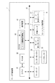
次に、図2の制御ブロック図を参照し、テープ印刷装置1の制御構成について説明する。テープ印刷装置1は、CPU(Central Processing Unit)81、RAM(Random Access Memory)82、ROM(Read Only Memory)83、表示画面41、キーボード3、カッターモーター25、テープカッター23、テープ送りモーター26、印刷ヘッド7およびテープ識別センサー27を備え、各構成要素は、バス85を介して接続されている。
Next, the control configuration of the tape printer 1 will be described with reference to the control block diagram of FIG. The tape printer 1 includes a CPU (Central Processing Unit) 81, a RAM (Random Access Memory) 82, a ROM (Read Only Memory) 83, a
CPU81は、中央処理装置であり、請求項における「印刷データ生成部」の主要部を為す。RAM82は、CPU81と直接接続されており、CPU81が各種制御を行う際のワークエリアとして用いられる。ROM83は、CPU81が各種制御を行うための制御プログラムおよび制御情報を記憶している。制御プログラムとしては、具体的に、表示画面41の表示制御を行うための表示制御プログラム、印刷処理行うための印刷処理プログラム等を記憶している(図示省略)。また、ROM83は、テープTのカット位置に印刷するカットマークCMの画像データ(マーク画像)を記憶するマーク画像記憶領域84を有している。CPU81は、上記の余白設定、カット設定に応じて、ユーザーが編集したラベル画像100に余白101、カットマークCM等を追加して印刷データを生成する(後に詳述する)。
The
表示画面41は、編集結果や印刷レイアウトを表示するための表示部として機能する。キーボード3は、ユーザーが情報を入力するための入力部、編集処理を行うための編集部、各種設定を行うための設定部、などとして機能する。
The
カッターモーター25は、テープカッター23と接続され、切断部として機能する。また、テープ送りモーター26および印刷ヘッド7は、テープTを搬送しながら当該テープT上に印刷を行う印刷部として機能する。また、上記のとおり、印刷ヘッド7およびテープ識別センサー27は、カートリッジ装着部6に設けられ、テープ識別センサー27は、テープカートリッジCに収容されたテープTの種別を検出する。CPU81は、このテープ識別センサー27の検出結果に基づいて(テープ材質や幅等に基づいて)、テキストとして入力可能な行数および文字数の制限、切断可能か否かの判別、などを行う。そして、印刷指示に応じて、印刷ヘッド7、カッターモーター25、テープ送りモーター26の駆動制御(印刷/切断制御)を行う。なお、請求項における「ラベル作成部」とは、主に、印刷ヘッド7、テープ識別センサー27、カッターモーター25、テープカッター23およびテープ送りモーター26を指す。
The
ここで、図3および図4を参照して、通常印刷および連続印刷における、余白設定およびカット設定と、カットマークCMの印刷位置と、の関係について説明する。図3は、通常印刷(1枚印刷)における印刷済みのテープTを示した模式図である。通常印刷(1枚印刷)においては、同図(a)、(b)に示すように、余白設定が「極少(余白101:1mm)」である場合に、ラベル画像100の先端位置に追加された前余白のさらに先端位置にカットマークCMが印刷される。一方、同図(c)、(d)に示すように、余白設定が「極少」以外である場合には、カットマークCMは印刷されない。なお、同図(a)、(c)に示すように、カット設定が「自動カットあり」である場合は、印刷された1枚のラベル画像100の後端位置に追加された後余白の後端位置が、テープ印刷装置1(テープカッター23)により自動カットされる。一方、同図(b)、(d)に示すように、カット設定が「自動カットなし」である場合は、後端位置が自動カットされない。
Here, with reference to FIG. 3 and FIG. 4, the relationship between the margin setting and the cut setting and the printing position of the cut mark CM in normal printing and continuous printing will be described. FIG. 3 is a schematic diagram showing a printed tape T in normal printing (single sheet printing). In normal printing (single-sheet printing), as shown in FIGS. 5A and 5B, when the margin setting is “extremely small (margin 101: 1 mm)”, the
図4は、連続印刷(複数枚印刷:図示では3枚)における印刷済みのテープTを示した模式図である。同図(a)に示すとおり、余白設定が「極少」且つカット設定が「自動カットあり」の場合、ラベル画像100の前余白の先端位置にカットマークCMが印刷され、各ラベル画像100の後余白の後端位置が自動カットされる。同図(b)に示すとおり、余白設定が「極少」且つカット設定が「自動カットなし」の場合、すべてのラベル画像100の前余白の先端位置にカットマークCMが印刷される。同図(c)に示すとおり、余白設定が「極少」以外且つカット設定が「自動カットあり」の場合、カットマークCMは全く印刷されず、各ラベル画像100の後余白の後端位置が自動カットされる。同図(d)に示すとおり、余白設定が「極少」以外且つカット設定が「自動カットなし」であるときは、2枚目以降のラベル画像100の前余白の先端位置にのみカットマークCMが印刷される。
FIG. 4 is a schematic diagram showing a printed tape T in continuous printing (printing a plurality of sheets: three sheets in the drawing). As shown in FIG. 5A, when the margin setting is “extremely” and the cut setting is “automatic cut”, the cut mark CM is printed at the leading edge position of the front margin of the
続いて、図5を参照し、本実施形態のカットマークCMについて詳細に説明する。同図(a)は、図4(b)に示す、連続印刷において、余白設定が「極少」且つカット設定が「自動カットなし」である場合の印刷済みのテープTを示している。同図(b)は、同図(a)に示すテープTを、カットマークCMの前端および後端の2箇所を切断して形成されたラベルである。すなわち、連続印刷されるすべてのラベル画像100の先端近傍にカットマークCMが印刷される場合を例に挙げて、説明する。なお、図3および図4に示したその他の場合でも、印刷位置が同一であれば、テープ印刷装置1は、以下に説明するカットマークCMと同様のものをテープTに印刷するものとする。
Next, the cut mark CM of this embodiment will be described in detail with reference to FIG. FIG. 4A shows the printed tape T when the margin setting is “extremely” and the cut setting is “no automatic cut” in the continuous printing shown in FIG. 4B. FIG. 2B is a label formed by cutting the tape T shown in FIG. 2A at the front end and the rear end of the cut mark CM. That is, the case where the cut mark CM is printed near the front end of all the
図5(a)に示すように、テープTは、後にユーザーがハサミ等で手動切断した後にラベルとなるラベルエリアA1,2,3と、各ラベルエリアAの先端に位置するカットマークエリアB1,2,3と、を有している。ラベルエリアA1,2,3は、その中央位置にユーザーが編集したラベル画像100が配置され、当該ラベル画像100の印刷方向における両サイドに余白101がそれぞれ設けられている。この余白101は、余白設定「極少」により1mmとなっている。なお、請求項における「実領域」とは、ラベルエリアAを示す。また、請求項における「不要領域」とは、カットマークエリアBおよびテープTの先端からカットマークエリアB1までの領域を示す。
As shown in FIG. 5A, the tape T includes label areas A1, 2, and 3 that become labels after the user manually cuts with scissors later, and cut mark areas B1, which are positioned at the leading ends of the label areas A. 2 and 3. In the label areas A 1, 2, and 3, the
カットマークエリアB1,2,3には、カットマークCMが配置されている。カットマークCMは、テープTのカット位置の指標となるものであり、図示のように、テープTの長手方向に所定の幅を有する長方形を太線で縁取った枠画像で構成されている。このように、枠画像でカットマークCMを構成することにより、印字汚れ等と誤認されない存在感のあるカットマークCMを印刷することができる。なお、カットマークCMがテープTの長手方向に幅を有しているため、マーク上をカットすると明らかにマークの一部がカット後のラベルに残ってしまうことから、図5(b)のように、ユーザーがカットマークCMを避けて(カットマークCMの前端および後端の2箇所)テープTを切断することが望ましい。 Cut marks CM are arranged in the cut mark areas B1, 2, and 3. The cut mark CM serves as an index of the cut position of the tape T, and is composed of a frame image in which a rectangle having a predetermined width in the longitudinal direction of the tape T is bordered by a thick line as shown in the figure. In this way, by forming the cut mark CM with the frame image, it is possible to print the cut mark CM having a presence that is not mistaken for print stains or the like. Since the cut mark CM has a width in the longitudinal direction of the tape T, a part of the mark clearly remains on the cut label when the mark is cut, as shown in FIG. In addition, it is desirable that the user cut the tape T while avoiding the cut mark CM (two locations at the front end and the rear end of the cut mark CM).
図6は、上記以外のカットマークCMの例を示したものである。同図(a)に示すカットマークCM2は、内部が塗りつぶされた長方形の画像で構成されている。また、同図(b)に示すカットマークCM3は、枠画像のテープ長方向の片方の辺が抜け、且つこれを90°回転した「コ」の字状の画像で構成されている。同図(c)に示すカットマークCM4は、ハサミを模った画像で構成されている。これらのように、枠画像以外の画像でカットマークCMを構成しても良い。 FIG. 6 shows an example of the cut mark CM other than the above. The cut mark CM2 shown in FIG. 5A is composed of a rectangular image whose inside is filled. Further, the cut mark CM3 shown in FIG. 5B is constituted by a “U” -shaped image in which one side of the frame image in the tape length direction is missing and rotated 90 °. The cut mark CM4 shown in FIG. 5C is composed of an image simulating scissors. As described above, the cut mark CM may be composed of an image other than the frame image.
また、カットマークCMを、キャラクタ情報と画像を組み合わせたものとしてもよい。例えば、同図(d)に示すカットマークCM5は、枠画像の内部に「カット位置」という文字と、実際のカット位置の方向を指す複数の矢印と、が印刷されている。これによれば、よりユーザーにわかりやすくカット位置を示すことができる。また、同図(c)に示すカットマークCM6は、「カット位置」という文字および実際のカット位置の方向を指す複数の矢印の画像のみが印刷されている。これによれば、カット位置がずれた場合でも、枠画像がないために、マークが残りにくい。 The cut mark CM may be a combination of character information and an image. For example, in the cut mark CM5 shown in FIG. 4D, characters “cut position” and a plurality of arrows indicating the direction of the actual cut position are printed inside the frame image. According to this, it is possible to show the cut position more easily for the user. In the cut mark CM6 shown in FIG. 5C, only the characters “cut position” and a plurality of arrows indicating the direction of the actual cut position are printed. According to this, even when the cut position is deviated, there is no frame image, so the mark is difficult to remain.
なお、これら以外にも、カットマークCMは、テープ長方向に所定の長さを有し、カットマークの両外側がカット位置であることを示すものであればよい。 In addition to these, the cut mark CM only needs to have a predetermined length in the tape length direction and indicate that both outer sides of the cut mark are cut positions.
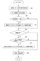
次に、図7を参照して、本実施形態のラベル作成処理について説明する。なお、本処理では、予めユーザーの操作によって余白設定、カット設定および連続印刷するか否かが、設定されているものとする。テープ印刷装置1は、ユーザーの[印刷]キーの押下(S01)をトリガとして、印刷処理を開始する。先ず、テープ印刷装置1は、ユーザーが編集したラベル画像100(1個もしくは複数個)の両隣に、余白設定に応じた所定の長さの余白101を追加する(S02)。このラベル画像100および2つの余白101の画像データが上記のラベルエリアAを構成する画像データとなる。次に、本余白設定が「極少(余白101:1mm)」であった場合(S03:Yes)、最初に印刷するラベルエリアAの先端にカットマークCMのマーク画像を追加する(S04)。このマーク画像が上記のカットマークエリアB1を構成する画像データとなる。一方、余白設定が「極少」以外であった場合は(S03:No)、印刷データにマーク画像を追加せずに、次のフローに進む。
Next, with reference to FIG. 7, the label creation processing of this embodiment will be described. In this process, it is assumed that margin settings, cut settings, and whether or not to perform continuous printing are set in advance by a user operation. The tape printer 1 starts the printing process with the user's pressing of the [PRINT] key (S01) as a trigger. First, the tape printing apparatus 1 adds a
続いて、連続印刷且つカット設定が「自動カットなし」であった場合(S05:Yes、S06:Yes)、2枚目以降のラベルエリアA(2,3…)の先端にマーク画像を追加する(S07)。そして、生成した印刷データをテープTに印刷し、カット設定に応じて切断処理を行う(S08)。一方、通常印刷(1枚印刷)であった場合(S05:No)、または、連続印刷であってカット設定が「自動カットあり」であった場合は(S06:No)、印刷データにカットマークCMを追加せずに、印刷処理を実行する。 Subsequently, when continuous printing and the cut setting is “no automatic cut” (S05: Yes, S06: Yes), a mark image is added to the leading edge of the second and subsequent label areas A (2, 3,...). (S07). Then, the generated print data is printed on the tape T, and cutting processing is performed according to the cut setting (S08). On the other hand, if it is normal printing (single-sheet printing) (S05: No), or if it is continuous printing and the cut setting is “with automatic cutting” (S06: No), a cut mark is included in the print data. Print processing is executed without adding a CM.
これまで説明したテープ印刷装置によれば、カットマークCMがテープ長方向幅を有しているため、印字汚れ等に誤認されたり、見落とされることのないカットマークCMを印刷することができる。また、カットマークCMがラベルとなるラベルエリアAの外部であるカットマークエリアBに印刷されるため、ユーザーに対しテープ長方向に幅を有するカットマークCMを印刷しつつも、所望のテープ長のラベルを得ることができる。 According to the tape printer described so far, since the cut mark CM has a width in the tape length direction, it is possible to print the cut mark CM that is not mistakenly recognized by printing stains or overlooked. Further, since the cut mark CM is printed in the cut mark area B outside the label area A to be a label, the user can print the cut mark CM having a width in the tape length direction while printing the desired tape length. A label can be obtained.
続いて、図8を参照し、本実施形態の変形例について詳細に説明する。なお、上述した実施例と同じ構成については、同様の符号を付して詳細な説明を省略する。同図は、図5と同様に連続印刷されるすべてのラベル画像100の先端にカットマークCMが印刷された場合を示している。
Next, a modification of the present embodiment will be described in detail with reference to FIG. In addition, about the same structure as the Example mentioned above, the same code | symbol is attached | subjected and detailed description is abbreviate | omitted. This figure shows a case where cut marks CM are printed at the leading ends of all the
図8(a)に示すように、テープTは、手動切断した後にラベルとなるラベルエリアA1,2,3と、各ラベルエリアAの先端に位置するカットマークエリアB1,2,3と、を有している。ラベルエリアA1,2,3には、ラベル画像100と、その前後に配置された2つの余白101が設けられている。一方、カットマークエリアB1,2,3には、隣り合うラベルエリアAの端から切代102を介してカットマークCMが配置されている。カットマークCMは、カットマークエリアBの領域幅よりも僅かに短く設定されており、ラベルエリアAとカットマークCMとの間に切代102が設けられている。この切代102は、テープTの長手方向に0.3〜0.5mmの幅を有していることが望ましい。また、カットマークの幅は、切代102の幅よりも大きいことが望ましい。
As shown in FIG. 8A, the tape T includes label areas A1, 2, and 3 that become labels after manual cutting, and cut mark areas B1, 2, and 3 that are positioned at the tips of the label areas A. Have. In the label areas A1, 2, and 3, a
なお、図8(a)に示すように、カットマークエリアB1は、最初に印刷されるラベルエリアA1の先端位置に設けられているため、切代102は、ラベルエリアA1に隣接する片側にのみ設けられている。一方、カットマークエリアB2,3は、両隣にラベルエリアAが配置されているため、カットマークCMの両隣に切代102が設けられている。なお、請求項における不要領域として設定され得る最小の領域幅とは、本変形例におけるカットマークエリアB1を示す。
As shown in FIG. 8A, since the cut mark area B1 is provided at the leading end position of the label area A1 to be printed first, the cutting
本変形例では、テープ印刷装置1は、余白設定が「極少」である場合に最初のラベルエリアA1の先端に切代102を追加して、さらにその先端にカットマークCMのマーク画像を追加する。また、連続印刷であってカット設定が「自動カットなし」であった場合に、2枚目以降のラベルエリアA2,3の先端に切代102、マーク画像、切代102の順に追加して印刷データを生成する。
In the present modification, when the margin setting is “extremely”, the tape printer 1 adds the cutting
本変形例によれば、カットマークCMがテープTの長手方向に幅を有しているため、マーク上をカットすると明らかにマークの一部がカット後のラベルに残ってしまうことから、ユーザーがカットマークCMを避けてテープTを切断することが考えられるが、この切断は、ラベルエリアAとカットマークCMとの間に設けられた切代102で行われるため、ラベルエリアAを侵すことがない(図8(b)参照)。すなわち、ユーザーがカットマークCMを避けてテープTを切断しても、所望の長さを有したラベルを作成することができる。
According to this modification, since the cut mark CM has a width in the longitudinal direction of the tape T, when the mark is cut, a part of the mark clearly remains on the cut label. It is conceivable to cut the tape T while avoiding the cut mark CM. However, since this cutting is performed at the cutting
1:テープ印刷装置 7:印刷ヘッド 81:CPU 84:マーク画像記憶領域 100:ラベル画像 101:余白 102:切代 A:ラベルエリア B:カットマークエリア CM:カットマーク T:テープ 1: Tape printer 7: Print head 81: CPU 84: Mark image storage area 100: Label image 101: Margin 102: Cutting margin A: Label area B: Cut mark area CM: Cut mark T: Tape
Claims (7)
前記ラベルの長手方向に所定の長さ(但し、長さ0を除く)を有する前記カットマークの画像データであり、前記ラベルの不要領域の少なくとも一部として印刷されるマーク画像を記憶するマーク画像記憶部と、
前記ラベルの実領域に印刷されるラベル画像の、前記長手方向における隣接位置に前記マーク画像を付加して印刷データを生成する印刷データ生成部と、
前記印刷データをテープ状部材に印刷し、前記ラベルを作成するラベル作成部と、を備えたことを特徴とするラベル作成装置。 A label producing apparatus capable of printing a cut mark serving as an index when manually cutting the label in the width direction in order to separate an actual area and an unnecessary area of the label after creating the label,
A mark image that stores image data of the cut mark having a predetermined length (excluding length 0) in the longitudinal direction of the label and printed as at least a part of the unnecessary area of the label A storage unit;
A print data generation unit that generates print data by adding the mark image to an adjacent position in the longitudinal direction of a label image printed in the real area of the label;
A label producing apparatus comprising: a label producing unit that produces the label by printing the print data on a tape-like member.
前記ラベルの長手方向に所定の長さ(但し、長さ0を除く)を有する前記カットマークの画像データであり、前記ラベルの不要領域の少なくとも一部として印刷されるマーク画像を記憶するマーク画像記憶ステップと、
前記ラベルの実領域に印刷されるラベル画像の、前記長手方向における隣接位置に前記マーク画像を付加して印刷データを生成する印刷データ生成ステップと、
前記印刷データをテープ状部材に印刷し、前記ラベルを作成するラベル作成ステップと、を実行することを特徴とするラベル作成装置の制御方法。 A method for controlling a label producing apparatus capable of printing a cut mark serving as an index when manually cutting the label in the width direction in order to separate an actual area and an unnecessary area of the label after creating the label,
A mark image that stores image data of the cut mark having a predetermined length (excluding length 0) in the longitudinal direction of the label and printed as at least a part of the unnecessary area of the label A memory step;
A print data generation step of generating print data by adding the mark image to an adjacent position in the longitudinal direction of a label image printed in the real area of the label;
And a label producing step of producing the label by printing the print data on a tape-like member.
Priority Applications (1)
| Application Number | Priority Date | Filing Date | Title |
|---|---|---|---|
| JP2011000502A JP2012139952A (en) | 2011-01-05 | 2011-01-05 | Label forming device and control method for label forming device |
Applications Claiming Priority (1)
| Application Number | Priority Date | Filing Date | Title |
|---|---|---|---|
| JP2011000502A JP2012139952A (en) | 2011-01-05 | 2011-01-05 | Label forming device and control method for label forming device |
Publications (1)
| Publication Number | Publication Date |
|---|---|
| JP2012139952A true JP2012139952A (en) | 2012-07-26 |
Family
ID=46676729
Family Applications (1)
| Application Number | Title | Priority Date | Filing Date |
|---|---|---|---|
| JP2011000502A Pending JP2012139952A (en) | 2011-01-05 | 2011-01-05 | Label forming device and control method for label forming device |
Country Status (1)
| Country | Link |
|---|---|
| JP (1) | JP2012139952A (en) |
Cited By (6)
| Publication number | Priority date | Publication date | Assignee | Title |
|---|---|---|---|---|
| JP2017074754A (en) * | 2015-10-16 | 2017-04-20 | コニカミノルタ株式会社 | Image forming apparatus and image forming method |
| CN110730714A (en) * | 2017-07-14 | 2020-01-24 | 佐治亚-太平洋波纹有限责任公司 | Controls for paper, sheet and cartridge manufacturing systems |
| US11093186B2 (en) | 2017-07-14 | 2021-08-17 | Georgia-Pacific Corrugated Llc | Engine for generating control plans for digital pre-print paper, sheet, and box manufacturing systems |
| US11449290B2 (en) | 2017-07-14 | 2022-09-20 | Georgia-Pacific Corrugated Llc | Control plan for paper, sheet, and box manufacturing systems |
| US11520544B2 (en) | 2017-07-14 | 2022-12-06 | Georgia-Pacific Corrugated Llc | Waste determination for generating control plans for digital pre-print paper, sheet, and box manufacturing systems |
| US11807480B2 (en) | 2017-07-14 | 2023-11-07 | Georgia-Pacific Corrugated Llc | Reel editor for pre-print paper, sheet, and box manufacturing systems |
-
2011
- 2011-01-05 JP JP2011000502A patent/JP2012139952A/en active Pending
Cited By (9)
| Publication number | Priority date | Publication date | Assignee | Title |
|---|---|---|---|---|
| JP2017074754A (en) * | 2015-10-16 | 2017-04-20 | コニカミノルタ株式会社 | Image forming apparatus and image forming method |
| CN110730714A (en) * | 2017-07-14 | 2020-01-24 | 佐治亚-太平洋波纹有限责任公司 | Controls for paper, sheet and cartridge manufacturing systems |
| US11093186B2 (en) | 2017-07-14 | 2021-08-17 | Georgia-Pacific Corrugated Llc | Engine for generating control plans for digital pre-print paper, sheet, and box manufacturing systems |
| US11449290B2 (en) | 2017-07-14 | 2022-09-20 | Georgia-Pacific Corrugated Llc | Control plan for paper, sheet, and box manufacturing systems |
| US11485101B2 (en) | 2017-07-14 | 2022-11-01 | Georgia-Pacific Corrugated Llc | Controls for paper, sheet, and box manufacturing systems |
| US11520544B2 (en) | 2017-07-14 | 2022-12-06 | Georgia-Pacific Corrugated Llc | Waste determination for generating control plans for digital pre-print paper, sheet, and box manufacturing systems |
| US11807480B2 (en) | 2017-07-14 | 2023-11-07 | Georgia-Pacific Corrugated Llc | Reel editor for pre-print paper, sheet, and box manufacturing systems |
| US11907595B2 (en) | 2017-07-14 | 2024-02-20 | Georgia-Pacific Corrugated Llc | Control plan for paper, sheet, and box manufacturing systems |
| US11911992B2 (en) | 2017-07-14 | 2024-02-27 | Georgia-Pacific Corrugated Llc | Controls for paper, sheet, and box manufacturing systems |
Similar Documents
| Publication | Publication Date | Title |
|---|---|---|
| JP5753415B2 (en) | Printing apparatus and printing apparatus control method | |
| JP2012139952A (en) | Label forming device and control method for label forming device | |
| JP2009039893A (en) | Tape printer and program thereof | |
| JP4635691B2 (en) | Data display method for data display device, data display device, data generation device provided with the same, and sheet processing device | |
| JP5560810B2 (en) | Tape printer, method for determining paragraph arrangement of tape printer, and program thereof | |
| JP2012139953A (en) | Label forming device and control method of label forming device | |
| JP5375568B2 (en) | Information processing apparatus and control method thereof | |
| JP5548988B2 (en) | Printing device, label producing method, and storage medium storing program relating to label producing method | |
| JP2010224703A (en) | Information processing apparatus, tape printer, and program | |
| JP2010214787A (en) | Printer and tape printer | |
| JP5736773B2 (en) | Tape printing apparatus, printing control method for tape printing apparatus, program, and printed matter | |
| JP2010026554A (en) | Documentation apparatus and tape printing apparatus | |
| JP5739697B2 (en) | Printing apparatus and printing apparatus control method | |
| JP4564878B2 (en) | Data creation device control method, data creation device, tape processing system, and program | |
| JP3912396B2 (en) | Character information processing method | |
| JP5552965B2 (en) | Tape printer and control method of tape printer | |
| JP2006053312A (en) | Character information processing method, character information processor, program and storage medium | |
| JP2009101527A (en) | Information processor, tape printing apparatus, character string display method in information processor, and program | |
| JP6327526B2 (en) | Printing device | |
| JP2012179726A (en) | Tape printing apparatus and method for controlling the same | |
| JP5577950B2 (en) | Tape printer and control method of tape printer | |
| JP5240391B2 (en) | Tape printer and program | |
| JP6924401B2 (en) | Printing equipment | |
| JP2009012360A (en) | Label production apparatus and tag production apparatus | |
| JP2014133376A (en) | Printer, and control method thereof |
Legal Events
| Date | Code | Title | Description |
|---|---|---|---|
| RD02 | Notification of acceptance of power of attorney |
Free format text: JAPANESE INTERMEDIATE CODE: A7422 Effective date: 20130509 |
|
| RD04 | Notification of resignation of power of attorney |
Free format text: JAPANESE INTERMEDIATE CODE: A7424 Effective date: 20130509 |