JP2012138658A - Imaging apparatus - Google Patents
Imaging apparatus Download PDFInfo
- Publication number
- JP2012138658A JP2012138658A JP2010287878A JP2010287878A JP2012138658A JP 2012138658 A JP2012138658 A JP 2012138658A JP 2010287878 A JP2010287878 A JP 2010287878A JP 2010287878 A JP2010287878 A JP 2010287878A JP 2012138658 A JP2012138658 A JP 2012138658A
- Authority
- JP
- Japan
- Prior art keywords
- photographer
- image
- imaging
- imaging unit
- face
- Prior art date
- Legal status (The legal status is an assumption and is not a legal conclusion. Google has not performed a legal analysis and makes no representation as to the accuracy of the status listed.)
- Pending
Links
- 238000003384 imaging method Methods 0.000 title claims abstract description 126
- 238000003860 storage Methods 0.000 claims description 16
- 238000001514 detection method Methods 0.000 abstract description 31
- 230000015654 memory Effects 0.000 description 16
- 230000006870 function Effects 0.000 description 8
- 239000002131 composite material Substances 0.000 description 7
- 238000000034 method Methods 0.000 description 7
- 230000003287 optical effect Effects 0.000 description 7
- 239000004973 liquid crystal related substance Substances 0.000 description 5
- 239000000203 mixture Substances 0.000 description 5
- 230000009471 action Effects 0.000 description 4
- 230000008859 change Effects 0.000 description 3
- 230000008569 process Effects 0.000 description 3
- 238000005520 cutting process Methods 0.000 description 2
- 230000000994 depressogenic effect Effects 0.000 description 2
- 238000011156 evaluation Methods 0.000 description 2
- 238000003825 pressing Methods 0.000 description 2
- 230000004044 response Effects 0.000 description 2
- 101100150128 Schizosaccharomyces pombe (strain 972 / ATCC 24843) spo14 gene Proteins 0.000 description 1
- 238000006243 chemical reaction Methods 0.000 description 1
- 230000006835 compression Effects 0.000 description 1
- 238000007906 compression Methods 0.000 description 1
- 238000010586 diagram Methods 0.000 description 1
- 239000000284 extract Substances 0.000 description 1
- 230000008921 facial expression Effects 0.000 description 1
- 238000009432 framing Methods 0.000 description 1
- 230000007246 mechanism Effects 0.000 description 1
- 230000002093 peripheral effect Effects 0.000 description 1
- 238000002360 preparation method Methods 0.000 description 1
- 230000035945 sensitivity Effects 0.000 description 1
- 238000000926 separation method Methods 0.000 description 1
- 230000003936 working memory Effects 0.000 description 1
Images

Landscapes
- Studio Devices (AREA)
- Exposure Control For Cameras (AREA)
- Details Of Cameras Including Film Mechanisms (AREA)
- Cameras In General (AREA)
- Camera Bodies And Camera Details Or Accessories (AREA)
- Structure And Mechanism Of Cameras (AREA)
Abstract
Description
本発明は、一般の被写体の他に撮影者自身の顔も同時に撮影できる撮像装置に関するものである。 The present invention relates to an imaging apparatus capable of simultaneously photographing a photographer's own face in addition to a general subject.
主撮像手段,副撮像手段を備え、同時に2つの画像を撮像するカメラ一体型ビデオレコーダ(特許文献1)や画像記録装置(特許文献2)が知られている。主撮像手段が生成する主画像は、撮影者により任意選択された撮影対象を撮影した画像データとなる。一方、副撮像手段は、撮影レンズを本体部の後方向に向けて取り付けられており、副撮像手段が生成する副画像は、撮影者の容姿(例えば、顔面の表情も含まれる)を撮像した画像データとなる。各画像データは、それぞれ別々の媒体(ビデオテープとメモリカード)に記録される。各画像データには、同一のタイムコードが付されているので、撮像終了後、主画像の一隅に副画像をはめ込む画像合成が行なわれる。 A camera-integrated video recorder (Patent Document 1) and an image recording device (Patent Document 2) that include a main imaging unit and a sub-imaging unit and capture two images simultaneously are known. The main image generated by the main image pickup means is image data obtained by shooting a shooting target arbitrarily selected by the photographer. On the other hand, the sub-imaging unit is attached with the photographing lens facing the rear of the main body, and the sub-image generated by the sub-imaging unit images the photographer's appearance (for example, facial expression is also included). It becomes image data. Each image data is recorded on a separate medium (video tape and memory card). Since the same time code is attached to each image data, image composition is performed in which a sub-image is inserted into one corner of the main image after the imaging is completed.
一方、近年、「FaceTime」(登録商標)や「SKYPE(スカイプ)」(登録商標)が登場し、上述したような主,副画像を同時に撮影して画像合成を行なうことが、一部の携帯電話で可能になり、普及の兆しを見せている。 On the other hand, in recent years, “FaceTime” (registered trademark) and “SKYPE” (registered trademark) have appeared, and it is possible to synthesize images by simultaneously capturing the main and sub images as described above. It becomes possible by telephone and shows signs of widespread use.
携帯電話は、紛失した場合、他人によって、簡単に使用される危険性がある。特に、上記のような主,副画像を撮影可能な携帯電話では、所有者等の顔画像が記録されているため、紛失した場合のリスクが一般の携帯電話以上に高いという欠点がある。 If a mobile phone is lost, there is a risk that it will be easily used by others. In particular, in the mobile phone capable of taking the main and sub images as described above, since the face image of the owner or the like is recorded, there is a disadvantage that the risk of being lost is higher than that of a general mobile phone.
本発明は、上記課題を鑑みてなされたものであり、所有者や許可された者のみが撮影できるセキュリティ機能を備えた撮像装置を提供することを目的とする。 The present invention has been made in view of the above problems, and an object thereof is to provide an imaging apparatus having a security function that allows only the owner or an authorized person to photograph.
本発明の撮像装置は、装置本体の前方へ向けて設けられた第1撮影レンズを備え、前記装置本体の前方を撮影する主撮像部と、前記装置本体の少なくとも後方へ向けられるように設けられた第2撮影レンズを備え、前記装置本体の少なくとも後方を撮影する副撮像部と、前記撮影者の少なくとも顔画像が予め登録された記憶手段と、前記副撮像部によって撮像された撮影者の顔画像と前記記憶手段に予め登録された撮影者の顔画像とを比較し、両者が一致した場合のみに主撮像部による撮影を許可する制御手段とを備えたことを特徴とする。 An imaging apparatus according to the present invention includes a first imaging lens provided toward the front of the apparatus main body, and is provided so as to be directed at least to the rear of the apparatus main body and a main imaging unit that images the front of the apparatus main body. A second imaging lens that captures at least the back of the apparatus main body, storage means in which at least a face image of the photographer is registered in advance, and the face of the photographer captured by the sub-imaging unit Control means for comparing the image with the face image of the photographer registered in advance in the storage means, and permitting photographing by the main imaging unit only when they match each other.
前記制御手段は、前記副撮像部によって撮像された撮影者の顔画像と前記記憶手段に予め登録された撮影者の顔画像とを比較し、両者が一致しない場合、装置の電源をオフにすることが好ましい。 The control means compares the photographer's face image captured by the sub-imaging unit with the photographer's face image registered in advance in the storage means, and if both do not match, the apparatus is turned off. It is preferable.
前記記憶手段に予め登録された顔画像は互いに異なる複数の撮影者の顔画像であるとともに、登録された撮影者の顔画像には、前記撮影者の固有情報が添付され、前記制御手段は、前記主撮像部の撮像操作が許可された撮影者の固有情報を許可日時と一緒に記憶手段に記憶することが好ましい。 The face images registered in advance in the storage means are face images of a plurality of different photographers, and the photographer's unique information is attached to the registered photographer's face images, and the control means includes: Preferably, the unique information of the photographer permitted to perform the imaging operation of the main imaging unit is stored in the storage unit together with the permitted date and time.
前記固有情報に、前記撮影者が設定した撮影条件のカスタム設定データが含まれている場合、前記制御手段は、前記撮像操作が許可された撮影者のカスタム設定データに基づいて、撮影条件の設定を行なうことが好ましい。 When the specific information includes custom setting data of shooting conditions set by the photographer, the control unit sets shooting conditions based on the custom setting data of the photographer permitted to perform the imaging operation. Is preferably performed.
前記固有情報に、前記撮影者の特定の動作データが含まれている場合、前記制御手段は、前記副撮像部によって撮像された撮影者の動作が、前記特定の動作データの動作に一致したタイミングで、前記特定の動作データに対応した所定のシーケンスを実行することが好ましい。 When the specific information includes the specific motion data of the photographer, the control unit is configured to determine when the motion of the photographer imaged by the sub-imaging unit coincides with the motion of the specific motion data. Therefore, it is preferable to execute a predetermined sequence corresponding to the specific operation data.
前記第2撮影レンズは、前記装置本体の前方へ向けられた位置と後方へ向けられた位置との間で回動自在に設けられていることが好ましい。 It is preferable that the second photographing lens is provided so as to be rotatable between a position directed to the front and a position directed to the rear of the apparatus main body.
本発明の撮像装置によれば、副撮像部によって撮像された撮影者の顔画像と記憶手段に予め登録された撮影者の顔画像とを比較し、両者が一致した場合のみに主撮像部の撮像操作を許可する制御手段とを備えたので、所有者や許可された者のみが撮影できる。 According to the imaging apparatus of the present invention, the photographer's face image captured by the sub-imaging unit is compared with the photographer's face image registered in advance in the storage means, and only when the two match, Since the control means for permitting the imaging operation is provided, only the owner or an authorized person can take an image.
副撮像部によって撮像された撮影者の顔画像と記憶手段に予め登録された撮影者の顔画像とを比較し、両者が一致しない場合、装置の電源をオフにするので、所有者や許可された者以外の不審な者に使用されることが防止できる。 The photographer's face image captured by the sub-imaging unit is compared with the photographer's face image registered in advance in the storage means, and if they do not match, the apparatus is turned off. It can be prevented from being used by suspicious persons other than those who are not.
主撮像部の撮像操作が許可された撮影者の固有情報を許可日時と一緒に記憶手段に記憶するので、装置の使用履歴が残され、誰がいつ使用したのかが分かる。これにより、撮影画像が誰によって撮影されたものか分かるので、画像の整理等に役に立つ。 Since the unique information of the photographer who is permitted to perform the imaging operation of the main imaging unit is stored in the storage unit together with the permitted date and time, the usage history of the apparatus is left and it is possible to know who used when. As a result, the photographed image can be identified by the photographer, which is useful for organizing images.
撮影者のカスタム設定データに基づいて撮影条件が設定されるので、撮影者が変わる毎に好みの撮影条件にわざわざ設定し直す必要がなく、撮影者が変わってもその撮影者の好みの撮影条件で素早く撮影することができる。 Shooting conditions are set based on the photographer's custom setting data, so you don't have to set your favorite shooting conditions every time the photographer changes. You can shoot quickly.
撮影者の固有情報に撮影者の特定の動作データが含まれている場合、撮影者の動作が特定の動作データの動作に一致したタイミングで、特定の動作データに対応した所定のシーケンスが実行されるので、手で直接的に操作しなくても、デジタルカメラの所定のシーケンスを実行することができる。例えば、撮影者の固有情報に顔画像の特定の動作データが含まれている場合、撮影者の顔画像の動作が特定の動作に一致したタイミングで、少なくとも主撮像部の撮像動作が自動的に実行されるので、手が使えない状況下でも撮影することができる。このため、手が不自由な障害者でも撮影することができる。また、特定の動作として、「手の動作」を用いることもできる。例えば、グーでフォーカスし、パーでシャッタレリーズしたり、指の数を3,2,1,と変化させると、次の瞬間にシャッタレリーズされるなど、あらかじめ登録された動作が副撮像部により検出され一致した時に、予め登録された対応したシーケンスが実行されるようにできる。 When the photographer's specific information includes the photographer's specific motion data, a predetermined sequence corresponding to the specific motion data is executed at the timing when the photographer's motion matches the motion of the specific motion data. Therefore, it is possible to execute a predetermined sequence of the digital camera without directly operating by hand. For example, when specific action data of a face image is included in the photographer's unique information, at least the image pickup operation of the main image pickup unit is automatically performed at the timing when the action of the photographer's face image matches the specific action. Because it is executed, you can shoot even in situations where you cannot use your hands. Therefore, even a handicapped person with a handicap can take a picture. Also, “hand movement” can be used as the specific movement. For example, if the focus is set to go and the shutter is released with par, or the number of fingers is changed to 3, 2, 1, or the like, the shutter is released at the next moment. When they match, the corresponding sequence registered in advance can be executed.
副撮像部の第2撮影レンズを装置本体の前方へ向けられた位置と後方へ向けられた位置との間で回動自在に設けたので、第2撮影レンズを装置本体の前方へ向けることにより、主撮像部と同時に副撮像部でも装置本体の前方を撮影することができる。主撮像部の第1撮影レンズと副撮像部の第2撮影レンズとを互いに異なる画角に設定してあれば、装置本体前方の同じ被写体を同時に異なる画角で撮影することができる。 Since the second imaging lens of the sub-imaging unit is provided so as to be rotatable between a position directed to the front of the apparatus body and a position directed to the rear, the second imaging lens is directed to the front of the apparatus body. The front of the apparatus main body can be photographed by the sub imaging unit at the same time as the main imaging unit. If the first photographing lens of the main imaging unit and the second photographing lens of the sub-imaging unit are set to different angles of view, the same subject in front of the apparatus main body can be simultaneously photographed at different angles of view.
本発明の撮像装置の実施形態であるデジタルカメラ10は、二つの撮像部である主撮像部31,副撮像部32(図4参照)を備え、二つの画像を合成して表示、記録できるとともに、副撮像部32によって撮影者を撮影することにより、撮影者がデジタルカメラ10の所有者や所有者によって使用が許可された者(以下、所有者を含めて使用許可者という)であるのか、デジタルカメラ10を不正に取得するなどして許可無く使用しようとしている者(以下、使用不許可者という)であるのかを判別し、使用不許可者の場合には、警告が表示された後、操作できないようにデジタルカメラ10の電源を強制的にオフにするセキュリティ機能を備えている。 The digital camera 10 which is an embodiment of the imaging apparatus of the present invention includes a main imaging unit 31 and a sub imaging unit 32 (see FIG. 4) which are two imaging units, and can display and record two images by combining them. Whether the photographer is a person who is permitted to use by the owner or owner of the digital camera 10 (hereinafter referred to as an authorized person including the owner) by photographing the photographer by the sub-imaging unit 32. It is determined whether the digital camera 10 is a person who intends to use it without permission by illegally obtaining it (hereinafter referred to as a use-permitted person). In the case of a use-disabled person, a warning is displayed, A security function for forcibly turning off the power of the digital camera 10 is provided so that it cannot be operated.
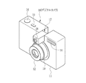
図1に示すように、デジタルカメラ10のカメラ本体11の前面には、主撮像部31の撮像光学系が組み込まれたレンズ鏡筒12の他、フラッシュ発光部14が設けられている。カメラ本体11の上部には、デジタルカメラ10の電源をオン/オフする電源ボタン15、シャッタレリーズ操作に用いられるシャッタボタン16、そして、副撮像部32が内蔵された四角柱形状の副撮像ユニット17が設けられている。
As shown in FIG. 1, in addition to the
副撮像ユニット17は、カメラ本体11の長手方向に設けられた回転軸(図示せず)の周りに180度の角度範囲で回動自在に取り付けられている。副撮像ユニット17の一端面には、副撮像部32の撮像光学系が組み込まれたレンズ鏡筒18が僅かに突出して設けられ、副撮像ユニット17の回転角度によって、レンズ鏡筒18が撮影者側や、レンズ鏡筒12と同じ主被写体側(図2参照)に向けられる。
The
デジタルカメラ10のセキュリティ機能が有効に機能するためには、少なくとも電源をオフからオンにするために電源ボタン15を押圧操作する直前には、副撮像ユニット17のレンズ鏡筒18が撮影者側に向いている必要がある。このため、デジタルカメラ10の電源をオンからオフにするために電源ボタン15を押圧すると、電源が即座にオフにされるのではなく、レンズ鏡筒18が撮影者側に向いているか、副撮像ユニット17の位置がセンサやマイクロスイッチ等(図示せず)によりチェックされ、レンズ鏡筒18が撮影者側に向いていない場合には、撮像ユニット17の向きを直すよう警告が後述するLCD24に表示され、電源はオフにならない。
In order for the security function of the digital camera 10 to function effectively, at least immediately before the
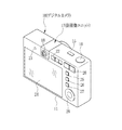
主被写体とは、カメラ本体11の前方に存在し、主に主撮像部31によって撮影される撮影者自身以外の被写体を意味し、特定の人物や物や風景を指す文言ではない。なお、図2に示すように、副撮像ユニット17のレンズ鏡筒18がカメラ本体11の前方に向けられた場合、主被写体は副撮像ユニット17によっても撮影される。
The main subject means a subject other than the photographer himself / herself, which is present in front of the
レンズ鏡筒12は沈胴式になっており、デジタルカメラ10が電源オフ状態にある際に、デジタルカメラ10の前面に設けられた鏡筒収納部19内に収納され、電源オンとともにデジタルカメラ10の前面から突出して、広角端で停止する。また、カメラ本体11の背面に設けられたズーム操作ボタン20(図3参照)の操作によって、レンズ鏡筒12が前進及び後退してズーム倍率が変更される。
The
カメラ本体11の背面側を示す図3において、ズーム操作ボタン20と副撮像ユニット17との間には、モード設定ボタン22が配設されている。モード設定ボタン22は、凸状のつまみを左右に移動させることにより、副撮像ユニット17で撮影するか否か(副撮像部32を用いて撮影するか否か)を切り替える。つまり、モード設定ボタン22は、副撮像部32を使用せずに主撮像部31のみで撮影する通常撮影モードか、主撮像部31と同期して副撮像部32でも撮影を行ない合成画像を作成する合成撮影モードかのいずれかを選択する。なお、主撮像部31を使用せずに副撮像部32だけを使用するモードも理論上は可能であるが、実用上使用される可能性が低いため、本実施形態では用意されていない。
In FIG. 3 showing the back side of the
副撮像ユニット17のモード設定ボタン22と反対側の側方には、副撮像ユニット17によって撮影者が撮影される際に補助光を発光する白色LED23が配設されている。白色LED23の下方には、タッチパネル方式のLCD(液晶ディスプレイ)24が設けられ、その側方には、上方から動画ボタン25,メニューボタン26,再生ボタン27,及びコントローラホイール28が配設されている。コントローラホイール28を回すと、メニューの項目を選んだり画像の切り換えなどができ、撮影モードや再生モードでは、指をのせたホイールの位置に割り当てられた機能が表示される。また、コントローラホイール28は、後述する画像の合成時に、嵌め込む画像の位置を変更するのにも使用される。
On the side opposite to the
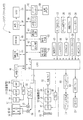
図4に示すように、主撮像部31は、レンズ鏡筒12、繰出しモータ33、フォーカスモータ34、モータドライバ35、撮像素子であるCMOSイメージセンサ36、タイミングジェネレータ(以下、TGと略す)37、デジタル信号処理回路(以下、DSPという)38、デジタル画像処理回路(以下、DIPという)39で構成される。
As shown in FIG. 4, the main imaging unit 31 includes a
レンズ鏡筒12には、撮像光学系(第1撮影レンズ)としてズームレンズ41、フォーカスレンズ42、絞り43が組み込まれている。レンズ鏡筒12の撮影位置への繰出しと、収納位置への沈胴は、繰出しモータ33の駆動によって行われる。ズームレンズ41及びフォーカスレンズ42の光軸方向への進退移動は、フォーカスモータ34の駆動によって行われる。各モータ33,34は、モータドライバ35に接続されている。モータドライバ35は、デジタルカメラ10を統括的に制御するCPU45に接続されており、CPU45からの制御信号に応じて各モータ33,34を駆動させる。
The
レンズ鏡筒12の背後には、CMOSイメージセンサ36が配置されている。レンズ鏡筒12の撮像光学系は、CMOSイメージセンサ36の受光面に被写体像を結像させる。CMOSイメージセンサ36は、TG37に接続されている。TG37は、CPU45に接続されており、CPU45の制御の下、タイミング信号(クロックパルス)をCMOSイメージセンサ36に入力する。CMOSイメージセンサ36は、このタイミング信号に応じて受光面に結像された被写体像の撮像を行い、被写体像に対応した撮像信号を出力する。
A
CMOSイメージセンサ36から出力された撮像信号は、DSP38に入力される。DSP38は、CMOSイメージセンサ36から入力される撮像信号に対して、色分離、色補間、ゲイン補正、ホワイトバランス調整、ガンマ補正等の各種信号処理を施し、画像データを生成する。DSP38で生成された画像データは、DIP39の作業メモリに入力される。DIP39は、DSP38で生成された画像データに対して、電子変倍、色強調処理、エッジ強調処理等の各種画像処理を施す。DIP39で各種画像処理が施された画像データは、主画像データとして画像メモリ46に一時的に蓄積される。
The imaging signal output from the
副撮像部32は、レンズ鏡筒18、撮像素子であるCMOSイメージセンサ47、TG48、DSP49、DIP50で構成される。レンズ鏡筒18の撮影光学系(第2撮影レンズ)は、被写界深度が深い広角系の固定焦点の撮影レンズ51である。撮影レンズ51の焦点距離は、撮影者がカメラ本体11を把持した状態で、撮影者の顔が前後に多少移動しても撮影者の顔にピントが合うように決められている。CMOSイメージセンサ47によって撮像され、DSP49、DIP50から出力された画像データは、副画像データとして画像メモリ52に一時的に蓄積される。
The sub-imaging unit 32 includes the
画像メモリ46,52は、データバス53を介してCPU45に接続されている。同様に、CPU45には、データバス53を介して、画像合成回路54、SDRAM55、液晶ドライバ56、メディアコントローラ57、AE/AWB検出回路61、AF検出回路62、顔検出回路63、顔照合回路64、及び切り取りパターン用メモリ66が接続されている。
The
CPU45には、電源ボタン15、シャッタボタン16、ズーム操作ボタン20、モード設定ボタン22、動画ボタン25、メニューボタン26、再生ボタン27、コントローラホイール28などの各操作部材が接続されている。これらの各操作部材は、ユーザによる操作を検出し、その検出結果をCPU45に入力する。
Connected to the
CPU45には、EEPROM67、フラッシュドライバ68、LEDドライバ69が接続されている。フラッシュドライバ68にはフラッシュ発光部12、LEDドライバ69には白色LED23が、それぞれ接続されている。撮影者に向けられた白色LED23は、多くの場合、撮影者の顔が逆光となることから、常時発光される。白色LED23の発光光量は、副撮像部32によって撮影された画像の明るさに応じて、LEDドライバ69によって随時変更される。
An
EEPROM67には、デジタルカメラ10を制御するための各種プログラムやデータが記憶されている。CPU45は、各種プログラムやデータを読み出して、各種処理を実行する。また、EEPROM67には、予めデジタルカメラ10の使用が許可された使用許可者の顔画像が登録されている。
The
液晶ドライバ56は、CPU45からの指示に応じてSDRAM55から所定の一画面分の画像データを読み出す。そして、液晶ドライバ56は、デジタルカメラの背面側に配設されたLCD24に対して、SDRAM55から読み出した一画面分の画像データに基づくスルー画像を表示させる。
The
メディアコントローラ57は、CPU45からの指示に応じてメディアスロットに着脱自在に装着された記録メディア59にアクセスし、記録メディア59に対して各一画面分の画像データの書込みを行う。この書込みに際しては、画像データは、予め設定された圧縮形式により圧縮される。なお、画像データは圧縮しないで記録メディア59に書き込むようにしてもよい。記録メディア59としては、各種のメモリカードが用いられる。
The
AE/AWB検出回路61は、各一画面分の画像データに設定されるAE検出領域の被写体輝度を検出し、検出した被写体輝度をCPU45に出力する。CPU45は、被写体輝度に基づいて、露出量、及びホワイトバランスの適否を判断し、CMOSイメージセンサ36、47のシャッタ速度、絞り43の絞り値を決定する。なお、CMOSイメージセンサ47側の絞りは、レンズ鏡筒18により決まる固定絞りであるから、露出制御は、シャッタ速度のみで調整される。このように、AE/AWB検出回路61及びCPU45は、自動露出機能及びオートホワイトバランス機能を制御する。
The AE /
AF検出回路62は、各一画面分の画像データに設定されるAF検出領域から高周波成分を抽出し、その高周波成分を積算したAF評価値をCPU45に出力する。CPU45は、モータドライバ35によってフォーカスモータ34を駆動し、AF評価値が最大、すなわちAF検出領域内のコントラストが最大となる合焦位置にフォーカスレンズ42を移動させる。これにより、焦点をAF検出領域内の被写体に合致させる。このように、AF検出回路62及びCPU45は、オートフォーカス機能を制御する。
The
顔検出回路63は、各一画面分の画像データに基づく撮像画像から、被写体の顔画像をそれぞれ検出する。顔画像の検出には、測光値から作成した色相値と彩度値とのヒストグラムを用いた方法(特開平05−158164号公報に開示)や、肌色検出を用いた方法(特開平07−306483号公報に開示)などを利用する。また、パターンマッチングを用いた技術を利用してもよい。
The
顔検出回路63で検出された顔画像は、AE検出領域、AF検出領域にそれぞれ割り当てられる。顔画像が検出されない場合には、予め設定されている例えば画像中央の適当なサイズの初期検出領域が、AE検出領域、AF検出領域にそれぞれ割り当てられる。
The face images detected by the
顔照合回路64は、副撮像部32で撮像され画像メモリ52に記憶された画像データから検出された顔画像と、EEPROM67に予め登録された使用許可者の顔画像とを比較し、検出された顔画像が使用許可者の顔画像と一致するか否かを判定する。
The
切り取りパターン用メモリ66には、顔検出回路63で検出された撮影者の顔の領域画像を切り取る際に用いられる切り取りパターンに関するデータが保存されている。この切り取りパターンには、例えば、矩形、楕円型、星型などがあり、ユーザーは、メニューボタン26、及びコントローラホイール28を操作することにより、所望のパターンを選択することができる。
The
電源ボタン15が押圧されると、図示を省略したバッテリの電力が各部に供給され、デジタルカメラ10が起動する。そして、電源ボタン15が再度押圧されると、電力の供給が停止され、デジタルカメラ10が停止状態になる。CPU45は、電源ボタン15の操作を検出すると、その操作に応じて繰出しモータ33を駆動し、レンズ鏡筒12の繰出し、あるいは沈胴を行わせる。
When the
シャッタボタン16は、二段階で押圧される。シャッタボタン16が軽く押圧(半押し)されると、主撮像部31において、AE処理やAF処理などの各種撮影準備処理が施される。そして、半押しされた状態からシャッタボタン16が強く押圧(全押し)されると、各撮像部31,32から出力された各画像データが画像メモリ46,52に記憶される。
The
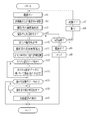
このように構成されたデジタルカメラ10の作用について、図5のフローチャートを参照して説明する。なお、括弧内のst(ステップの意)1等は、図5に示すst1等に対応する。副撮像ユニット17は、通常、図1,図3に示すように、撮影者側にレンズ鏡筒18の撮影レンズ51が向けられた位置にセットされている。電源ボタン15が押圧され、電源がデジタルカメラ10に投入されると(st1)、モード設定ボタン22の位置に関わらず、まず副撮像ユニット17に内蔵された副撮像部32が駆動される(st2)。副撮像部32の駆動に同期して、白色LED23が発光される。
The operation of the digital camera 10 configured as described above will be described with reference to the flowchart of FIG. In addition, st (meaning of step) 1 in the parenthesis corresponds to st1 etc. shown in FIG. The
CMOSイメージセンサ47によって撮像された撮影者の画像データは、副画像データとして画像メモリ52に一旦記憶されてから、データバス53を介して顔検出回路63に送られ、撮影者の顔画像が検出される(st3)。
The photographer's image data captured by the
顔検出回路63によって検出された顔画像は、顔照合回路64に送られる。顔照合回路64は、EEPROM67に予め登録された使用許可者の顔画像と照合し、顔検出回路63によって検出された顔画像が使用許可者の顔画像と一致するか否かを判定する(st4)。
The face image detected by the
顔検出回路63によって検出された顔画像が使用許可者のいずれの顔画像とも一致しない場合、CPU45の指令によって、LCD24の表示面に「操作が許可されません」等の警告文が表示(st6)されてから、例えば1秒経過後に、デジタルカメラ10の電源が強制的にオフにされる(st7)。この強制的な電源オフの回数が連続2回までは、再度電源ボタン15を押圧操作すれば、電源オンになる。強制的な電源オフの回数が連続3回に達すると(st5)、CPU45の指令によって、デジタルカメラ10の電源が強制的にオフ(st8)にされるだけでなく、電源ボタン15を再度押圧操作しても電源すら入らないロック状態にされる(st9)。
If the face image detected by the
顔検出回路63によって検出された撮影者の顔画像がEEPROM67に登録済みの顔画像と一致した場合、CPU45の指令によって、LCD24の表示面に「操作が許可されました」等の文言が表示された後、全ての操作が許可される(st10)。繰出しモータ33が駆動され、レンズ鏡筒12が収納位置から撮影位置へ繰り出される。操作が許可された直後は、通常撮影モードに設定され、主撮像部31の駆動が開始される。これにより、CMOSイメージセンサ36によって撮像された画像がLCD24にスルー画表示される。
When the photographer's face image detected by the
操作が許可された撮影者の固有情報がSDRAM55に読み込まれる(st11)。続いて、撮影者の固有情報のうち少なくとも撮影者を判別可能な固有情報と許可された日時情報とを一緒に記録としてEEPROM67に記憶する(st12)。これにより、装置の使用履歴が残され、誰がいつ使用したのかが分かる。撮影画像が誰によって撮影されたものか分かるので、画像の整理等に役に立つ。撮影者の固有情報には、撮影者の名前や所属の他、所望の撮影条件を設定するカスタム設定データ、シャッタレリーズ動作のトリガーとされる顔画像の特定な動作データなどがある。
The unique information of the photographer permitted to operate is read into the SDRAM 55 (st11). Subsequently, at least the unique information that can identify the photographer and the permitted date and time information among the unique information of the photographer are stored in the
SDRAM55に読み込まれた固有情報の中に撮影条件のカスタム設定データが含まれている場合(st13)、CPU45は、撮影者のカスタム設定データに基づいて、例えば、撮影者の好みの色合い、ホワイトバランス、感度などを、撮影条件として設定する(st14)。これにより、撮影者が変わる毎に好みの撮影条件にわざわざ設定し直す必要がなく、撮影者が変わってもその撮影者の好みの撮影条件で素早く撮影することができる。
When custom setting data of shooting conditions is included in the unique information read into the SDRAM 55 (st13), the
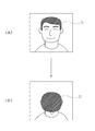
SDRAM55に読み込まれた固有情報の中に撮影者の顔画像の特定な動作データが含まれている場合(st15)、副撮像部32によって撮影される撮影者の顔画像が、例えば、図6(A),(B)に示す撮影者71の「お辞儀」のように、固有情報の中に予め登録された顔画像の特定の動作(お辞儀)を示す画像と一致すると(st16)、CPU45は、シャッタボタン15の押圧操作が無くても、自動的にシャッタレリーズ動作を実行し(st17)、主撮像部31による撮影が行なわれる。このため、手が使えない状況下でも撮影することができ、デジタルカメラ10を予め固定しておけば、手が不自由な障害者でも撮影することができる。
When specific operation data of a photographer's face image is included in the unique information read into the SDRAM 55 (st15), the photographer's face image photographed by the sub-imaging unit 32 is, for example, FIG. When the
撮影者71の顔は正面を向いているのが通常であるから、撮影者71の顔画像の特定な動作データとは、同図(B)に示すように、撮影者71の顔が下を向いて頭頂部が正面に向いた状態(お辞儀をした状態)を示す画像のデータである。
Since the face of the
主撮像部31から出力された画像データは、一旦画像メモリ46に記憶された後、SDRAM55に読み込まれ、ここから読み出されてメディアコントローラ57によって圧縮されて記録メディア59に書き込まれる。なお、顔画像の特定の動作の一例として、「お辞儀」を挙げたが、本発明はこれに限定されることなく、口を大きく開ける,顔を左右に振る等、通常の撮影時には行なわれることが極めて稀な動作の顔画像であればよい。また、顔画像の特定の動作によって、シャッタレリーズ動作を行なわせるようにしたが、本発明はこれに限定されることなく、フォーカス動作,セルフタイマのスタート動作などを行なわせるようにしてもよい。
The image data output from the main imaging unit 31 is temporarily stored in the
撮影者が自分自身も撮影して同じ画面に自分の顔画像を残したい場合、モード設定ボタン22を操作して合成撮影モードに設定する。これにより、副撮像部32が駆動を開始し、主撮像部31のCMOSイメージセンサ36と同期して同じ撮像タイミングでCMOSイメージセンサ47が撮影者自身の撮影を行なう。主撮像部31,副撮像部32から同時に出力された各画像データには、同じタイムコードが付与され、画像メモリ46,52に蓄積される。
When the photographer wants to photograph himself and leave his face image on the same screen, the
CPU45は、同じタイムコードが付与された各画像データを画像メモリ46,52から読み出し、一旦SDRAM55に記憶する。顔検出回路63は、撮影者の画像データから顔を検出し、選択された切り取りパターンに従って切り取る。切り取られた顔の領域画像の画像データと主被写体画像の画像データは、CPU45によって画像合成回路54に送られる。
The
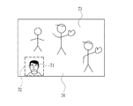
画像合成回路54では、図7に示すように、切り取られた顔の領域画像72の画像データが、主被写体画像73の画像データの周辺領域に合成され、合成画像データが生成される。この合成画像データは、一旦SDRAM55に保存されてから、CPU45によって液晶ドライバ56に送られることで、合成画像がLCD24に表示される。
In the
LCD24はタッチパネルであるから、領域画像72を指でタッチしてドラッグすれば、領域画像72をLCD24の表示画面(主被写体画像73)内で自由に移動させることができる。また、領域画像72を2本の指でタッチしたまま斜めに開いたり閉じたりすると、領域画像72の大きさ、すなわち撮影者71の大きさを変更することができる。領域画像72をLCD24の表示画面の全体まで拡大すると、主被写体画像73は領域画像72と入れ替わるように縮小されて、領域画像72の隅に表示される。
Since the
領域画像72の位置及び大きさが決まったら、LCD24で主被写体画像73を観察し、所望のフレーミングやタイミングでシャッタボタン16を深く押し下げる。これによって、撮像部31、32が同時に駆動され、同じタイムコードが付与された各画像データが画像メモリ46,52に記憶される。
When the position and size of the
撮影者の画像データは、顔検出回路63によって撮影者の顔が検出され、選択された切り取りパターンに従って切り取られた後、この撮影者の顔画像の画像データと主被写体画像の画像データとが画像合成回路54に送られ、LCD24上で予め決められた位置及び大きさで顔画像の画像データが主被写体画像の画像データに合成され、合成画像データが生成される。この合成画像データは、一旦SDRAM55に保存されてから、メディアコントローラ57に送られ、圧縮されてから記録メディア59に書き込まれる。
After the photographer's face is detected by the
動画ボタン25を押圧して動画モードに設定してからシャッタボタン16を押し下げれば、所定の時間内での動画撮影を行なうことができる。動画撮影の可能な撮影時間は、画像メモリ46,52の容量に依存する。この場合も、上述したような静止画撮影と同様に、LCD24上で撮影者の顔領域の位置及び大きさを決めてから、本番の動画撮影を行なうことができる。撮影された動画像は、例えばMP4ファイルフォーマットで記録メディア59に記録される。
If the moving image button 25 is pressed to set the moving image mode and then the
記録メディア59に書き込まれた静止画像や動画像を再生表示するには、再生ボタン27を押圧する。再生ボタン27を押圧すると、これまで記録メディア59に記録された各画像のサムネイル画像がLCD24に一覧表示されるので、再生表示したいサムネイル画像をタッチすることにより、その原画像である静止画像や動画像がLCD24の表示画面一杯に再生表示される。
In order to reproduce and display still images and moving images written in the
副撮像ユニット17を回動してレンズ鏡筒18を、図2に示すように、レンズ鏡筒12と同様に、カメラ本体11の前方へ向けることができる。これにより、レンズ鏡筒18の撮影レンズ51は広角系の固定焦点レンズであり、レンズ鏡筒12の撮影光学系は焦点距離が可変のズームレンズであるから、レンズ鏡筒12の撮影光学系の焦点距離をわざわざ撮影レンズ51の焦点距離と同じにしない限り、同じ被写体を異なる画角で同時に撮影することができる。
As shown in FIG. 2, the
レンズ鏡筒18がカメラ本体11の前方に向けられたまま電源ボタン15を押圧すると、レンズ鏡筒18が撮影者側に向いているか、副撮像ユニット17の位置がセンサやマイクロスイッチ等(図示せず)によりチェックされる。レンズ鏡筒18が撮影者側に向いていない場合には、CPU45の指令によって、例えば「副撮像ユニットの向きを元の位置に戻して下さい。」との警告文がLCD24に表示され、副撮像ユニット17の向きが直されるまで、電源はオフにされない。副撮像ユニット17の向きが直されると電源がオフになる。なお、副撮像ユニット17の向きが直されると、CPU45の指令によって、LCD24に「電源を切れる状態になりました。再度、電源ボタンを押して下さい。」との文言が表示され、再度、電源ボタンを押圧操作するようにしてもよい。
When the
なお、カメラ本体11に副撮像ユニット17を回転駆動する機構を設け、電源をオフにする際の電源ボタン15の押圧操作に応答して、レンズ鏡筒18が撮影者側に向いていない場合には、レンズ鏡筒18が撮影者側に向くように、自動的に副撮像ユニット17が回転されるようにしてもよい。
When the
以上説明した実施形態は、撮影者が使用不許可者と相違すると判定された場合、デジタルカメラを電源オフにし、3回連続して同じ判定の場合に電源オフしてロック状態となるようにしたが、本発明はこれに限定されることなく、例えば2回連続した場合や1回目から、電源オフしてロック状態になるようにしてもよい。 In the embodiment described above, when it is determined that the photographer is different from the unauthorized person, the digital camera is turned off, and the power is turned off in the same determination three times in a locked state. However, the present invention is not limited to this, and for example, the power may be turned off and the locked state may be entered after two consecutive times or from the first time.
上記実施形態では、特定の動作として、「顔の動作」の例を挙げたが、本発明はこれに限定されることなく、例えば、「手の動作」を用いることもできる。この場合、グーでフォーカスし、パーでシャッタレリーズしたり、また、指の数を3,2,1,と変化させると、次の瞬間にシャッタレリーズされるなど、あらかじめ登録された動作(グーやパーの手画像など)が副撮像部により検出され一致した時に、予め登録された対応したシーケンス(フォーカスやシャッタレリーズなど)が実行されるようにしてもよい。 In the above embodiment, the example of “face motion” is given as the specific motion, but the present invention is not limited to this, and for example, “hand motion” can also be used. In this case, if you focus with goo and release shutter with par, or change the number of fingers to 3, 2, 1, shutter release at the next moment etc. When a par hand image or the like is detected and matched by the sub-imaging unit, a corresponding sequence (focus, shutter release, etc.) registered in advance may be executed.
上記実施形態では、撮像素子としてCMOSイメージセンサを用いたが、本発明はこれに限定されることなく、例えばCCDイメージセンサを用いてもよい。なお、CCDイメージセンサを用いた場合、光電変換した信号電荷の取り出し方法がCMOSイメージセンサと異なるため、CCDイメージセンサに対応した回路(増幅回路等)が用いられる。 In the above-described embodiment, a CMOS image sensor is used as the image sensor. However, the present invention is not limited to this, and a CCD image sensor may be used, for example. When a CCD image sensor is used, a circuit (amplifier circuit or the like) corresponding to the CCD image sensor is used because a method for extracting signal charges obtained by photoelectric conversion is different from that of the CMOS image sensor.
上記実施形態では、副撮像ユニットをカメラ本体の上部に回動自在に配設したが、本発明はこれに限定されることなく、例えば、副撮像ユニットを、撮影レンズがカメラ本体の後方に常に向けられるように、カメラ本体の背面側に固定してもよい。 In the above embodiment, the sub-imaging unit is rotatably disposed on the upper part of the camera body. However, the present invention is not limited to this, and for example, the sub-imaging unit is always mounted on the rear side of the camera body. You may fix to the back side of a camera main body so that it may face.
上記実施形態では、本発明をデジタルカメラに適用した例であったが、本発明はこれに限定されることなく、例えば、デジタルビデオカメラや携帯電話に適用することもできる。デジタルビデオカメラに適用する場合、カメラ本体の側面に設けられた開閉式のLCDパネルの端部に、上記副撮像ユニット17をより小型化にして回動自在に設ければよい。動作については、デジタルカメラ10の動画モードと同様であるが、記録メディアとして大容量の小型ハードディスクやメモリカードを用いることにより、長時間(例えば数時間)の撮影を行なうことができる。
In the above embodiment, the present invention is applied to a digital camera. However, the present invention is not limited to this and can be applied to, for example, a digital video camera or a mobile phone. When the present invention is applied to a digital video camera, the
10 デジタルカメラ
12,18 レンズ鏡筒
17 副撮像ユニット
22 モード設定ボタン
24 LCD
31 主撮像部
32 副撮像部
36,47 CMOSイメージセンサ
45 CPU
46,52 画像メモリ
54 画像合成回路
63 顔検出回路
64 顔照合回路
66 切り取りパターン用メモリ
67 EEPROM
71 撮影者
72 領域画像
73 主被写体画像
DESCRIPTION OF SYMBOLS 10
31 Main imaging unit 32
46,52
71
Claims (6)
前記装置本体の少なくとも後方へ向けられるように設けられた第2撮影レンズを備え、前記装置本体の少なくとも後方を撮影する副撮像部と、
前記撮影者の少なくとも顔画像が予め登録された記憶手段と、
前記副撮像部によって撮像された撮影者の顔画像と前記記憶手段に予め登録された撮影者の顔画像とを比較し、両者が一致した場合のみに主撮像部による撮影を許可する制御手段と
を備えたことを特徴とする撮像装置。 A main imaging unit that includes a first photographic lens provided toward the front of the apparatus main body, and that images the front of the apparatus main body;
A second imaging lens provided so as to be directed at least to the rear of the apparatus main body, and a sub-imaging unit for photographing at least the rear of the apparatus main body;
Storage means in which at least a face image of the photographer is registered in advance;
A control unit that compares the photographer's face image captured by the sub-imaging unit with a photographer's face image registered in advance in the storage unit, and permits the photographing by the main imaging unit only when they match. An imaging apparatus comprising:
Priority Applications (1)
| Application Number | Priority Date | Filing Date | Title |
|---|---|---|---|
| JP2010287878A JP2012138658A (en) | 2010-12-24 | 2010-12-24 | Imaging apparatus |
Applications Claiming Priority (1)
| Application Number | Priority Date | Filing Date | Title |
|---|---|---|---|
| JP2010287878A JP2012138658A (en) | 2010-12-24 | 2010-12-24 | Imaging apparatus |
Publications (1)
| Publication Number | Publication Date |
|---|---|
| JP2012138658A true JP2012138658A (en) | 2012-07-19 |
Family
ID=46675773
Family Applications (1)
| Application Number | Title | Priority Date | Filing Date |
|---|---|---|---|
| JP2010287878A Pending JP2012138658A (en) | 2010-12-24 | 2010-12-24 | Imaging apparatus |
Country Status (1)
| Country | Link |
|---|---|
| JP (1) | JP2012138658A (en) |
Cited By (6)
| Publication number | Priority date | Publication date | Assignee | Title |
|---|---|---|---|---|
| JP2014212405A (en) * | 2013-04-17 | 2014-11-13 | キヤノン株式会社 | Imaging apparatus, control method, program, and storage medium |
| JP2014212404A (en) * | 2013-04-17 | 2014-11-13 | キヤノン株式会社 | Imaging apparatus, control method, program, and storage medium |
| JP2015126531A (en) * | 2013-12-27 | 2015-07-06 | キヤノン株式会社 | Image pickup device and control method of the same, and program |
| JP2016502348A (en) * | 2012-11-27 | 2016-01-21 | インターナショナル・ビジネス・マシーンズ・コーポレーションInternational Business Machines Corporation | Method using portable electronic device, portable electronic device, and computer program |
| JP2016057418A (en) * | 2014-09-09 | 2016-04-21 | カシオ計算機株式会社 | Imaging apparatus, imaging method and program |
| CN108989662A (en) * | 2013-09-30 | 2018-12-11 | 北京三星通信技术研究有限公司 | A kind of method and terminal device of control shooting |
-
2010
- 2010-12-24 JP JP2010287878A patent/JP2012138658A/en active Pending
Cited By (6)
| Publication number | Priority date | Publication date | Assignee | Title |
|---|---|---|---|---|
| JP2016502348A (en) * | 2012-11-27 | 2016-01-21 | インターナショナル・ビジネス・マシーンズ・コーポレーションInternational Business Machines Corporation | Method using portable electronic device, portable electronic device, and computer program |
| JP2014212405A (en) * | 2013-04-17 | 2014-11-13 | キヤノン株式会社 | Imaging apparatus, control method, program, and storage medium |
| JP2014212404A (en) * | 2013-04-17 | 2014-11-13 | キヤノン株式会社 | Imaging apparatus, control method, program, and storage medium |
| CN108989662A (en) * | 2013-09-30 | 2018-12-11 | 北京三星通信技术研究有限公司 | A kind of method and terminal device of control shooting |
| JP2015126531A (en) * | 2013-12-27 | 2015-07-06 | キヤノン株式会社 | Image pickup device and control method of the same, and program |
| JP2016057418A (en) * | 2014-09-09 | 2016-04-21 | カシオ計算機株式会社 | Imaging apparatus, imaging method and program |
Similar Documents
| Publication | Publication Date | Title |
|---|---|---|
| JP5056061B2 (en) | Imaging device | |
| CN101115113B (en) | Photographing apparatus and photographing method | |
| US8400547B2 (en) | Imaging apparatus and display control method in imaging apparatus | |
| JP5383356B2 (en) | IMAGING DEVICE, INFORMATION PROCESSING DEVICE, IMAGING DEVICE CONTROL METHOD, INFORMATION PROCESSING DEVICE CONTROL METHOD, AND COMPUTER PROGRAM | |
| WO2000076206A1 (en) | Electronic still camera | |
| CN102055906A (en) | Method and apparatus for guiding photographing | |
| KR101086409B1 (en) | Digital image processing device control method for photographing user set continuous shutter mode and device therefor | |
| JP5228354B2 (en) | Digital camera | |
| KR20100027700A (en) | Photographing method and apparatus | |
| JP2012138658A (en) | Imaging apparatus | |
| US7471328B2 (en) | Apparatus and method for rotating image in digital camera | |
| KR20060055645A (en) | Image display device and method using dual thumbnail mode | |
| US7317479B2 (en) | Automated zoom control | |
| JP5498059B2 (en) | Imaging apparatus, imaging method, reproduction method, image processing apparatus, and image processing program | |
| EP2080366B1 (en) | Image capture in auto-focus digital cameras | |
| JP4203380B2 (en) | Portable device with camera function and imaging method thereof | |
| CN102572232B (en) | Imaging apparatus and imaging method | |
| JP4717840B2 (en) | Imaging apparatus and control method thereof | |
| KR100627049B1 (en) | Apparatus and method for synthesizing an object to a captured image by a digital camera | |
| KR101436326B1 (en) | Digital photographing apparatus, method for controlling the same, and recording medium storing program to implement the method | |
| KR100673952B1 (en) | How to classify valid images from digital cameras | |
| JP4301885B2 (en) | Electronic camera | |
| KR101423918B1 (en) | Digital image processing apparatus which display a boundary image of an object and the controlling method of the same | |
| KR20090028328A (en) | Control method of digital image processing apparatus for face management and digital image processing apparatus employing this method | |
| KR101364535B1 (en) | Method of controlling digital image processing apparatus and apparatus thereof |