JP2012138317A - Lithium ion battery - Google Patents
Lithium ion battery Download PDFInfo
- Publication number
- JP2012138317A JP2012138317A JP2010291543A JP2010291543A JP2012138317A JP 2012138317 A JP2012138317 A JP 2012138317A JP 2010291543 A JP2010291543 A JP 2010291543A JP 2010291543 A JP2010291543 A JP 2010291543A JP 2012138317 A JP2012138317 A JP 2012138317A
- Authority
- JP
- Japan
- Prior art keywords
- ion battery
- negative electrode
- lithium ion
- formula
- positive electrode
- Prior art date
- Legal status (The legal status is an assumption and is not a legal conclusion. Google has not performed a legal analysis and makes no representation as to the accuracy of the status listed.)
- Pending
Links
Images
Classifications
-
- Y—GENERAL TAGGING OF NEW TECHNOLOGICAL DEVELOPMENTS; GENERAL TAGGING OF CROSS-SECTIONAL TECHNOLOGIES SPANNING OVER SEVERAL SECTIONS OF THE IPC; TECHNICAL SUBJECTS COVERED BY FORMER USPC CROSS-REFERENCE ART COLLECTIONS [XRACs] AND DIGESTS
- Y02—TECHNOLOGIES OR APPLICATIONS FOR MITIGATION OR ADAPTATION AGAINST CLIMATE CHANGE
- Y02E—REDUCTION OF GREENHOUSE GAS [GHG] EMISSIONS, RELATED TO ENERGY GENERATION, TRANSMISSION OR DISTRIBUTION
- Y02E60/00—Enabling technologies; Technologies with a potential or indirect contribution to GHG emissions mitigation
- Y02E60/10—Energy storage using batteries
Landscapes
- Secondary Cells (AREA)
- Battery Electrode And Active Subsutance (AREA)
Abstract
【課題】リチウムイオン電池の高充電,高温貯蔵時の劣化を抑制する。
【解決手段】リチウムイオンを吸蔵放出可能な正極と、リチウムイオンを吸蔵放出可能な負極と、正極と負極との間に配置されたセパレータと、電解液とを有するリチウムイオン電池において、前記電解液がルイス塩基として働く官能基を有するポリマーであるポリカチオンを含む電解液であることを特徴とする。特に、ポリカチオンとして、ポリアミノ酸,ポリアミン,ポリイミンの少なくともいずれかを含むことが好ましい。
【選択図】 図1An object of the present invention is to suppress deterioration of a lithium ion battery during high charge and high temperature storage.
A lithium ion battery comprising: a positive electrode capable of occluding and releasing lithium ions; a negative electrode capable of occluding and releasing lithium ions; a separator disposed between the positive electrode and the negative electrode; and an electrolytic solution. Is an electrolytic solution containing a polycation, which is a polymer having a functional group acting as a Lewis base. In particular, the polycation preferably contains at least one of polyamino acid, polyamine, and polyimine.
[Selection] Figure 1
Description
本発明は、リチウムイオン電池に関する。 The present invention relates to a lithium ion battery.
環境保護,省エネルギーの観点から、エンジンとモーターとを動カ源として併用したハイブリッド自動車が開発,製品化されている。また、将来的には、燃料電池をエンジンの替わりに用いる燃料電池ハイブリッド自動車の開発も盛んになっている。このハイブリッド自動車のエネルギー源として電気を繰返し充電放電可能な二次電池は必須の技術である。なかでも、リチウムイオン電池は、その動作電圧が高く、高い出力を得やすい高エネルギー密度の特徴を有する電池であり、今後、ハイブリッド自動車の電源として益々重要性が増している。 From the viewpoint of environmental protection and energy saving, hybrid vehicles that use an engine and a motor as a power source have been developed and commercialized. In the future, fuel cell hybrid vehicles that use fuel cells instead of engines are also actively developed. A secondary battery capable of repeatedly charging and discharging electricity as an energy source of this hybrid vehicle is an essential technology. Among them, the lithium ion battery is a battery having a high operating voltage and a high energy density that easily obtains a high output, and is becoming increasingly important as a power source for a hybrid vehicle in the future.
ハイブリッド自動車用電源として、リチウムイオン電池は、充電状態が高く50℃以上の高温貯蔵時の抵抗上昇抑制が、一つの技術課題である。従来、高温貯蔵時の抵抗上昇抑制策として、ビニレンカーボネート等の化合物を電解液に添加する対策が提案されている。 As a power source for a hybrid vehicle, one of the technical problems of a lithium ion battery is to suppress an increase in resistance when stored at a high temperature of 50 ° C. or higher. Conventionally, a countermeasure for adding a compound such as vinylene carbonate to an electrolytic solution has been proposed as a countermeasure for suppressing an increase in resistance during high-temperature storage.
例えば、非特許文献1に、LiPF6,エチレンカーボネート、及びジメチルカーボネートから構成される電解液に、ビニレンカーボネートを2wt%添加することで、60℃貯蔵時の劣化を抑制する電池が提案されている。
For example, Non-Patent
しかしながら、ビニレンカーボネートの活用技術では、添加量を増加させると高充電高温貯蔵時の劣化は抑制可能であるものの、室温での出力低下を招く問題がある。本発明の目的は、室温での出力特性を損なうことなく、高温・高充電貯蔵時にも劣化を抑制することが可能なリチウムイオン電池を提供することにある。 However, in the utilization technology of vinylene carbonate, although the deterioration at the time of high charge high temperature storage can be suppressed when the addition amount is increased, there is a problem in that the output at room temperature is reduced. An object of the present invention is to provide a lithium ion battery capable of suppressing deterioration even during storage at high temperature and high charge without impairing output characteristics at room temperature.
本発明は、リチウムイオンを吸蔵放出可能な正極と、リチウムイオンを吸蔵放出可能な負極と、正極と負極との間に配置されたセパレータと、電解液とを有するリチウムイオン電池において、前記電解液がルイス塩基として働く官能基を有するポリマーであるポリカチオンを含む電解液であることを特徴とする。ポリカチオンとしては、ポリアミノ酸,ポリアミン,ポリイミンなどが好ましい。 The present invention provides a lithium ion battery comprising: a positive electrode capable of occluding and releasing lithium ions; a negative electrode capable of occluding and releasing lithium ions; a separator disposed between the positive electrode and the negative electrode; and an electrolytic solution. Is an electrolytic solution containing a polycation, which is a polymer having a functional group acting as a Lewis base. As the polycation, polyamino acid, polyamine, polyimine and the like are preferable.
本発明によれば、リチウムイオン電池の室温での出力特性を維持した状態で、高充電高温貯蔵時の劣化を抑制することの可能なリチウムイオン電池を提供することができる。 ADVANTAGE OF THE INVENTION According to this invention, the lithium ion battery which can suppress deterioration at the time of a high charge high temperature storage can be provided in the state which maintained the output characteristic at the room temperature of a lithium ion battery.
リチウムイオン電池は、リチウムイオンを吸蔵放出可能な正極と、リチウムイオンを吸蔵放出可能な負極と、正極と負極との間に配置されたセパレータと、電解液とを備える。
本発明にかかるリチウムイオン電池は、ポリカチオンを含む電解液を使用していることを特徴とする。ポリカチオンは、ルイス塩基として働く官能基を有するポリマーである。
The lithium ion battery includes a positive electrode capable of occluding and releasing lithium ions, a negative electrode capable of occluding and releasing lithium ions, a separator disposed between the positive electrode and the negative electrode, and an electrolytic solution.
The lithium ion battery according to the present invention uses an electrolytic solution containing a polycation. The polycation is a polymer having a functional group that functions as a Lewis base.
充電状態が高く50℃以上の高温貯蔵時の劣化は、負極の容量の低下が主要因と考えられる。高温,高充電での長期間保存では、SEI構成成分の溶解や分解が進行し、負極中のLiと溶媒間の副反応が進行しやすくなる。その結果、Li消費が発生するとともに、SEIが成長資することにより劣化が進行する。 The main reason for the deterioration during high-temperature storage at a high charge state of 50 ° C. or higher is due to a decrease in the capacity of the negative electrode. In long-term storage at high temperature and high charge, dissolution and decomposition of SEI components proceed, and side reactions between Li in the negative electrode and the solvent tend to proceed. As a result, Li consumption occurs and deterioration progresses as SEI contributes to growth.
ポリカチオンは、分子内に含むルイス塩基の機能により、充電により負極電位が低下した場合に、静電的に負極表面に吸着する。その結果、吸着したポリカチオンがLiイオンの脱離を阻害し、結果として自己放電を抑制することが可能となると考える。 The polycation is electrostatically adsorbed on the surface of the negative electrode when the negative electrode potential is reduced by charging due to the function of the Lewis base contained in the molecule. As a result, it is considered that the adsorbed polycation inhibits Li ion desorption, and as a result, self-discharge can be suppressed.
ポリカチオンの吸着電位や吸着速度は、官能基の当電位点、分子量の制御により変化させることが可能である。リチウムイオン電池の用途や制御に合わせ、適宜ポリカチオンを選定することができる。 The adsorption potential and adsorption rate of the polycation can be changed by controlling the equipotential point of the functional group and the molecular weight. A polycation can be appropriately selected according to the use and control of the lithium ion battery.
前記ポリカチオンの例には、ポリリジン,ポリオルニチン,ポリヒスチジン,ポリアルギニン,ポリトリプトファン,ポリ−2,4−ジアミノブチリックアシッド,ポリ−2,3−ジアミノプロピオン酸、及びプロタミン、ならびにリジン,ヒスチジン,アルギニン,トリプトファン,オルニチン、2,4−ジアミノブチリックアシッド、及び、2,3−ジアミノプロピオン酸からなる群から選ばれる、少なくとも一種以上のアミノ酸の残基をポリペプチド鎖中に含むポリペプチドなどのポリアミノ酸;ポリアリルアミン,ポリビニルアミン,アリルアミンとジアリルアミンとの共重合物、及びポリジアリルアミンなどのポリアミン;ポリエチレンイミンなどのポリイミンが含まれる。ポリカチオンとして好ましくは、負極表面との静電的相互作用が強いルイス塩基を分子内に含むポリカチオンで、かつ負極上での分解抑制のため構造的に安定なポリカチオンが好ましく、より好ましい例にはポリアミノ酸が含まれ、さらに好ましい例にはポリリジンなどが含まれる。ポリリジンは、ε−ポリリジン,α−ポリリジン、またはαとεの混合されたポリリジンであってもよいが、好ましくはε−ポリリジンである。ε−ポリリジンの好ましい重合度は50以下である。重合度が高いと混合による電解液粘度上昇を招き、電池出力の低下を引き起こすため好ましくない。 Examples of the polycation include polylysine, polyornithine, polyhistidine, polyarginine, polytryptophan, poly-2,4-diaminobutyric acid, poly-2,3-diaminopropionic acid, and protamine, and lysine, histidine. A polypeptide chain containing at least one amino acid residue selected from the group consisting of arginine, tryptophan, ornithine, 2,4-diaminobutyric acid, and 2,3-diaminopropionic acid, etc. And polyamines such as polyallylamine, polyvinylamine, copolymers of allylamine and diallylamine, and polyamines such as polydiallylamine; and polyimines such as polyethyleneimine. The polycation is preferably a polycation containing a Lewis base having a strong electrostatic interaction with the negative electrode surface in the molecule, and a structurally stable polycation for suppressing decomposition on the negative electrode, more preferred examples. Includes polyamino acids, and more preferred examples include polylysine. The polylysine may be ε-polylysine, α-polylysine, or polylysine mixed with α and ε, but is preferably ε-polylysine. The preferable degree of polymerization of ε-polylysine is 50 or less. If the degree of polymerization is high, the viscosity of the electrolytic solution is increased by mixing, and the battery output is lowered, which is not preferable.
電解液にポリカチオンを含むリチウムイオン電池は、これまでリチウムイオン電池にくらべ、室温での出力特性を損なうことなく、50℃以上の高温貯蔵時の劣化を抑制したリチウムイオン電池を提供できるため、50℃以上の高温にさらされる可能性のあるハイブリッド自動車の電源,自動車の電動制御系の電源やバックアップ電源として広く利用可能であり、電動工具,フォークリフトなどの産業用機器の電源としても好適である。 Lithium ion batteries containing polycations in the electrolyte solution can provide a lithium ion battery that suppresses deterioration during storage at a high temperature of 50 ° C. or higher without impairing output characteristics at room temperature as compared with lithium ion batteries. It can be widely used as a power source for hybrid vehicles that may be exposed to high temperatures of 50 ° C or higher, a power source for electric control systems of vehicles, and a backup power source, and is also suitable as a power source for industrial equipment such as electric tools and forklifts. .
リチウムイオン電池の正極は、正極合剤層と、正極集電体とを有する。正極合剤層とは、正極活物質,導電性材料及び結着剤(バインダ)を含む正極合剤が、アルミニウム箔などの正極集電体に塗布されることにより形成される合剤層をいう。導電性材料は、電子抵抗の低減のための成分である。また、負極は、負極合剤と、銅箔などの負極集電体とを有し、負極合剤層とは、負極活物質,導電剤及び結着剤などを含む負極合剤が、負極集電体に塗布されることにより形成される合剤層をいう。 The positive electrode of a lithium ion battery has a positive electrode mixture layer and a positive electrode current collector. The positive electrode mixture layer refers to a mixture layer formed by applying a positive electrode mixture containing a positive electrode active material, a conductive material, and a binder (binder) to a positive electrode current collector such as an aluminum foil. . The conductive material is a component for reducing electronic resistance. The negative electrode includes a negative electrode mixture and a negative electrode current collector such as a copper foil. The negative electrode mixture layer includes a negative electrode mixture containing a negative electrode active material, a conductive agent, a binder, and the like. A mixture layer formed by being applied to an electric body.
正極活物質は、組成式LiαMnxM1yM2zO2(式中、M1は、Co,Niから選ばれる少なくとも1種、M2は、Co,Ni,Al,B,Fe,Mg,Crから選ばれる少なくとも1種であり、x+y+z=1,0<α<1.2,0.2≦x≦0.6,0.2≦y≦0.4,0.05≦z≦0.4)で表されるリチウム複合酸化物が好ましい。また、その中でも、M1がNi又はCoであって、M2がCo又はNiであることがより好ましい。組成中、Niを多くすると容量が大きく取れ、Coを多くすると低温での出力が向上でき、Mnを多くすると材料コストを抑制できる。特に、LiMn1/3Ni1/3Co1/3O2は、低温特性とサイクル安定性とが高く、ハイブリット自動車(HEV)用リチウム電池材料として好適である。また、添加元素は、サイクル特性を安定させるのに効果がある。他に、一般式LiMxPO4(M:Fe又はMn、0.01≦X≦0.4)やLiMn1-xMxPO4(M:Mn以外の2価のカチオン、0.01≦X≦0.4)である空間群Pmnbの対称性を有する斜方晶のリン酸化合物でも良い。
The positive electrode active material has a composition formula Li α Mn x M 1 y M 2 z O 2 (wherein
また、負極活物質は、炭素質材料,IV属元素を含む酸化物,IV属元素を含む窒化物の少なくとも1種を有することが好ましい。 The negative electrode active material preferably includes at least one of a carbonaceous material, an oxide containing a group IV element, and a nitride containing a group IV element.
負極活物質としては、例えば、天然黒鉛、天然黒鉛に乾式のCVD(Chemical Vapor Deposition)法や湿式のスプレイ法で形成される被膜を形成した複合炭素質材料,エポキシやフェノール等の樹脂原料若しくは石油や石炭から得られるピッチ系材料を原料として焼成して造られる人造黒鉛,非晶質炭素材料などの炭素質材料、又は、リチウムと化合物を形成することでリチウムを吸蔵放出できるリチウム金属,リチウムと化合物を形成し、結晶間隙に挿入されることでリチウムを吸蔵放出できる珪素,ゲルマニウム,錫など第四族元素の酸化物若しくは窒化物を用いることができる。なお、これらを一般的に負極活物質と称する場合がある。特に、炭素質材料は、導電性が高く、低温特性,サイクル安定性の面から優れた材料である。炭素質材料の中では、炭素網面層間(d002)の広い材料が急速充放電や低温特性に優れ、好適である。しかし、d002が広い材料は、充電の初期での容量低下や充放電効率が低いことがあるので、d002は0.390nm以下が好ましく、このような炭素質材料を、擬似異方性炭素と称する場合がある。更に、電極を構成するには黒鉛質,非晶質,活性炭などの導電性の高い炭素質材料を混合しても良い。または、黒鉛質材料として、以下(1)〜(3)に示す特徴を有する材料を用いても良い。
(1)ラマン分光スペクトルで測定される1300〜1400cm-1の範囲にあるピーク強度(ID)とラマン分光スペクトルで測定される1580〜1620cm-1の範囲にあるピーク強度(IG)との強度比であるR値(ID/IG)が、0.20以上0.40以下
(2)ラマン分光スペクトルで測定される1300〜1400cm-1の範囲にあるピークの半値幅Δ値が、40cm-1以上100cm-1以下
(3)X線回折における(110)面のピーク強度(I(110))と(004)面のピーク強度(I(004))との強度比X値(I(110)/I(004))が0.10以上0.45以下
バインダは、正極負極を構成する材料と、集電体を密着させるものであればよく、例えば、フッ化ビニリデン,四フッ化エチレン,アクリロニトリル,エチレンオキシドなどの単独重合体又は共重合体,スチレン−ブタジエンゴムなどを挙げることができる。導電剤は、例えば、カーボンブラック,グラファイト,カーボンファイバー及び金属炭化物などのカーボン材料であり、それぞれ単独でも混合して用いても良い。
Examples of the negative electrode active material include natural graphite, a composite carbonaceous material in which a film formed by dry CVD (Chemical Vapor Deposition) method or wet spray method is formed on natural graphite, resin raw materials such as epoxy and phenol, or petroleum And carbonaceous materials such as artificial graphite and amorphous carbon materials produced by firing pitch materials obtained from coal and coal as raw materials, or lithium metal that can occlude and release lithium by forming a compound with lithium, lithium An oxide or nitride of a Group 4 element such as silicon, germanium, or tin that can occlude and release lithium by forming a compound and inserting it into the crystal gap can be used. In some cases, these are generally referred to as negative electrode active materials. In particular, the carbonaceous material is a material having high conductivity, and excellent in terms of low temperature characteristics and cycle stability. Among the carbonaceous materials, a material having a wide carbon network surface layer (d 002 ) is excellent in rapid charge / discharge and low temperature characteristics, and is suitable. However, since a material with a wide d 002 may have a reduced capacity and a low charge / discharge efficiency at the initial stage of charging, d 002 is preferably 0.390 nm or less. May be called. Furthermore, a carbonaceous material having high conductivity such as graphite, amorphous, activated carbon or the like may be mixed to constitute the electrode. Alternatively, a material having the characteristics shown in (1) to (3) below may be used as the graphite material.
(1) peak in the range of 1300~1400Cm -1 measured by Raman spectrum intensity (I D) and the peak intensity in the range of 1580~1620Cm -1 as measured by Raman spectroscopy spectra (I G) and the The R value (I D / I G ), which is an intensity ratio, is 0.20 or more and 0.40 or less. (2) The peak half-value width Δ value in the range of 1300 to 1400 cm −1 measured by a Raman spectrum is 40 cm -1 or more 100 cm -1 or less (3) the intensity ratio X values of the peak intensity of the (110) plane in X-ray diffraction (I (110)) and (004) plane peak intensity (I (004)) (I (110) / I (004) ) is 0.10 or more and 0.45 or less. The binder may be any material as long as the material constituting the positive electrode and the current collector are in close contact with each other. For example, vinylidene fluoride, tetrafluoride Single weight of ethylene, acrylonitrile, ethylene oxide, etc. Body or copolymer, styrene - butadiene rubber and the like. The conductive agent is, for example, a carbon material such as carbon black, graphite, carbon fiber, and metal carbide, and each may be used alone or in combination.
電解液は、非水溶媒に電解質を溶解させてなる。溶媒としては、下記(式1)(式2)(式3)(式4)で表される化合物が好ましい。 The electrolytic solution is obtained by dissolving an electrolyte in a non-aqueous solvent. As a solvent, the compound represented by the following (Formula 1) (Formula 2) (Formula 3) (Formula 4) is preferable.

(式中、R1,R2,R3,R4は、水素,フッ素,塩素,炭素数1〜3のアルキル基,フッ素化されたアルキル基のいずれかを表わす。) (In the formula, R 1 , R 2 , R 3 and R 4 represent any one of hydrogen, fluorine, chlorine, an alkyl group having 1 to 3 carbon atoms, and a fluorinated alkyl group.)
(式中、R5,R6は、水素,フッ素,塩素,炭素数1〜3のアルキル基,フッ素化されたアルキル基のいずれかを表わす。) (In the formula, R 5 and R 6 represent any one of hydrogen, fluorine, chlorine, an alkyl group having 1 to 3 carbon atoms, and a fluorinated alkyl group.)
(式中、R7,R8は水素,フッ素,塩素,炭素数1〜3のアルキル基,フッ素化されたアルキル基のいずれかを表わし、R7,R8はそれぞれ同一でも異なっていても良い。) (In the formula, R 7 and R 8 represent hydrogen, fluorine, chlorine, an alkyl group having 1 to 3 carbon atoms, or a fluorinated alkyl group, and R 7 and R 8 may be the same or different. good.)
(式中、Z1,Z2は、アリル基,メタリル基,ビニル基,アクリル基,メタクリル基のいずれかを含む重合性官能基を表わす。) (In the formula, Z 1 and Z 2 represent a polymerizable functional group containing any of an allyl group, a methallyl group, a vinyl group, an acrylic group, and a methacryl group.)
さらに(式1)で表される化合物の組成比率が18.0〜30.0vol%であり、(式2)で表される化合物の組成比率が76.0〜81.8vol%であり、(式3)で表される化合物の組成比率が0.1〜2.0vol%であることが好ましい。ここで(式3)や(式4)で表される化合物の組成比率が2.0vol%以上となると、電池の内部抵抗が上昇し、電池の出力低下を招くため好ましくない。 Furthermore, the composition ratio of the compound represented by (Formula 1) is 18.0 to 30.0 vol%, the composition ratio of the compound represented by (Formula 2) is 76.0 to 81.8 vol%, It is preferable that the composition ratio of the compound represented by Formula 3) is 0.1 to 2.0 vol%. Here, when the composition ratio of the compound represented by (Formula 3) or (Formula 4) is 2.0 vol% or more, the internal resistance of the battery is increased, and the output of the battery is decreased.
また、(式1)で表される化合物がエチレンカーボネートであり、(式2)で表される化合物がエチルメチルカーボネート又はジメチルカーボネートの少なくとも一つであり、(式3)で表される化合物がジメタリルカーボネートであることが好ましい。 Moreover, the compound represented by (Formula 1) is ethylene carbonate, the compound represented by (Formula 2) is at least one of ethyl methyl carbonate or dimethyl carbonate, and the compound represented by (Formula 3) is Dimethallyl carbonate is preferred.
(式1)で表される化合物としては、エチレンカーボネート(EC),トリフロロプロピレンカーボネート(TFPC),クロロエチレンカーボネート(ClEC),フルオロエチレンカーボネート(FEC),トリフロロエチレンカーボネート(TFEC),ジフロロエチレンカーボネート(DFEC),ビニルエチレンカーボネート(VEC)等を用いることができる。特に、負極電極上の被膜形成の観点からECを用いることが好ましい。また、少量(2vol%以下)のClECやFECやTFECやVECの添加も、電極被膜形成に関与し、良好なサイクル特性を提供する。更には、TFPCやDFECは、正極電極上の被膜形成の観点から、少量(2vol%以下)添加して用いてもよい。(式2)で表される化合物としては、ジメチルカーボネート(DMC),エチルメチルカーボネート(EMC),ジエチルカーボネート(DEC),メチルプロピルカーボネート(MPC),エチルプロピルカーボネート(EPC),トリフロロメチルエチルカーボネート(TFMEC)、1,1,1−トリフロロエチルメチルカーボネート(TFEMC)等を用いることができる。DMCは、相溶性の高い溶媒であり、EC等と混合して用いるのに好適である。DECは、DMCよりも融点が低く、低温(−30℃)特性には好適である。EMCは、分子構造が非対称であり、融点も低いので低温特性には好適である。EPC,TFMECは、プロピレン側鎖を有し、非対称な分子構造であるので、低温特性の調整溶媒として好適である。TFEMCは、分子の一部をフッ素化し、双極子モーメントが大きくなっており、低温でのリチウム塩の解離性を維持するに好適であり、低温特性に好適がある。(式3)で表される化合物としては、ビニレンカーボネート(VC),メチルビニレンカーボネート(MVC),ジメチルビニレンカーボネート(DMVC),エチルビニレンカーボネート(EVC),ジエチルビニレンカーボネート(DEVC)等を用いることができる。VCは、分子量が小さく、緻密な電極被膜を形成すると考えられる。VCにアルキル基を置換したMVC,DMVC,EVC,DEVC等は、アルキル鎖の大きさに従い、密度の低い電極被膜を形成すると考えられ、低温特性向上には有効に作用するものと考えられる。(式4)で表される化合物としては、例えば、ジメタリルカーボネート(DMAC)を挙げることができる。(式1)で表される化合物としては、エチレンカーボネート(EC),トリフロロプロピレンカーボネート(TFPC),クロロエチレンカーボネート(ClEC),フルオロエチレンカーボネート(FEC),トリフロロエチレンカーボネート(TFEC),ジフロロエチレンカーボネート(DFEC),ビニルエチレンカーボネート(VEC)等を用いることができる。特に、負極電極上の被膜形成の観点からECを用いることが好ましい。 Examples of the compound represented by (Formula 1) include ethylene carbonate (EC), trifluoropropylene carbonate (TFPC), chloroethylene carbonate (ClEC), fluoroethylene carbonate (FEC), trifluoroethylene carbonate (TFEC), and difluoro. Ethylene carbonate (DFEC), vinyl ethylene carbonate (VEC), etc. can be used. In particular, it is preferable to use EC from the viewpoint of film formation on the negative electrode. In addition, addition of a small amount (2 vol% or less) of ClEC, FEC, TFEC, or VEC is also involved in electrode film formation and provides good cycle characteristics. Furthermore, TFPC and DFEC may be used by adding a small amount (2 vol% or less) from the viewpoint of film formation on the positive electrode. Examples of the compound represented by (Formula 2) include dimethyl carbonate (DMC), ethyl methyl carbonate (EMC), diethyl carbonate (DEC), methyl propyl carbonate (MPC), ethyl propyl carbonate (EPC), and trifluoromethyl ethyl carbonate. (TFMEC), 1,1,1-trifluoroethyl methyl carbonate (TFEMC) and the like can be used. DMC is a highly compatible solvent and is suitable for use in a mixture with EC or the like. DEC has a lower melting point than DMC and is suitable for low temperature (−30 ° C.) characteristics. EMC is suitable for low temperature characteristics because of its asymmetric molecular structure and low melting point. Since EPC and TFMEC have propylene side chains and an asymmetric molecular structure, they are suitable as adjusting solvents for low temperature characteristics. TFEMC fluorinates part of the molecule and has a large dipole moment, which is suitable for maintaining the dissociation property of the lithium salt at a low temperature, and is suitable for low temperature characteristics. As the compound represented by (Formula 3), vinylene carbonate (VC), methyl vinylene carbonate (MVC), dimethyl vinylene carbonate (DMVC), ethyl vinylene carbonate (EVC), diethyl vinylene carbonate (DEVC), or the like may be used. it can. VC has a low molecular weight and is considered to form a dense electrode film. MVC, DMVC, EVC, DEVC, and the like in which an alkyl group is substituted for VC are considered to form an electrode film having a low density in accordance with the size of the alkyl chain, and are considered to act effectively to improve low-temperature characteristics. Examples of the compound represented by (Formula 4) include dimethallyl carbonate (DMAC). Examples of the compound represented by (Formula 1) include ethylene carbonate (EC), trifluoropropylene carbonate (TFPC), chloroethylene carbonate (ClEC), fluoroethylene carbonate (FEC), trifluoroethylene carbonate (TFEC), and difluoro. Ethylene carbonate (DFEC), vinyl ethylene carbonate (VEC), etc. can be used. In particular, it is preferable to use EC from the viewpoint of film formation on the negative electrode.
次に、電解液に用いる前記リチウム塩としては、特に限定はないが、無機リチウム塩では、LiPF6,LiBF4,LiClO4,LiI,LiCl,LiBr等、また、有機リチウム塩では、LiB[OCOCF3]4,LiB[OCOCF2CF3]4,LiPF4(CF3)2,LiN(SO2CF3)2,LiN(SO2CF2CF3)2等を用いることができる。特に、民生用電池で多く用いられているLiPF6は、品質の安定性から好適な材料である。また、LiB[OCOCF3]4は、解離性,溶解性が良好で、低い濃度で高い導電率を示すので有効な材料である。
Next, the lithium salt used in the electrolytic solution is not particularly limited, but for inorganic lithium salts, LiPF 6 , LiBF 4 , LiClO 4 , LiI, LiCl, LiBr, etc., and for organic lithium salts, LiB [OCOCF 3] 4, LiB [OCOCF 2 CF 3] 4, LiPF 4 (CF 3) 2, LiN (SO 2 CF 3) 2, LiN (SO 2
〔実施例〕
以下、本発明を実施するための最良の形態を具体的な実施例によって説明する。
(実施例1)
(捲回型電池の作製)
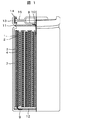
以下に示す方法で、本実施例の捲回型電池を作製した。図1に捲回型電池の片側断面図を示す。
〔Example〕
Hereinafter, the best mode for carrying out the present invention will be described with reference to specific examples.
Example 1
(Production of wound battery)
The wound type battery of this example was manufactured by the method described below. FIG. 1 shows a cross-sectional side view of a wound battery.
まず、正極活物質としてLiMn1/3Ni1/3Co1/3O2を用い、電子導電性材料としてカーボンブラック(CB1)と黒鉛(GF2)を用い、バインダとしてポリフッ化ビニリデン(PVDF)を用いて、乾燥時の固形分重量を、LiMn1/3Ni1/3Co1/3O2:CB1:GF2:PVDF=86:9:2:3の比となるように、溶剤としてNMP(N−メチルピロリドン)を用いて正極材ペーストを調製した。 First, LiMn 1/3 Ni 1/3 Co 1/3 O 2 is used as the positive electrode active material, carbon black (CB1) and graphite (GF2) are used as the electronic conductive material, and polyvinylidene fluoride (PVDF) is used as the binder. And the solid content weight at the time of drying is NMP (as a solvent so that the ratio of LiMn 1/3 Ni 1/3 Co 1/3 O 2 : CB1: GF2: PVDF = 86: 9: 2: 3 A positive electrode material paste was prepared using (N-methylpyrrolidone).
この正極材ペーストを、正極集電体1となるアルミ箔に塗布し、80℃で乾燥、加圧ローラでプレス、120℃で乾燥して正極合剤層2を正極集電体1に形成した。
This positive electrode material paste was applied to an aluminum foil to be the positive electrode
次に、負極活物質として非晶質炭素である擬似異方性炭素を用い、導電材としてカーボンブラック(CB2)を用い、バインダとしてPVDFを用いて、乾燥時の固形分重量を、擬似異方性炭素:CB2:PVDF=88:5:7の比となるように、溶剤としてNMPを用いて、負極材ペーストを調製した。 Next, pseudo-anisotropic carbon, which is amorphous carbon, is used as the negative electrode active material, carbon black (CB2) is used as the conductive material, and PVDF is used as the binder. A negative electrode material paste was prepared using NMP as a solvent so as to have a ratio of carbon: CB2: PVDF = 88: 5: 7.
この負極材ペーストを、負極集電体3となる銅箔に塗布し、80℃で乾燥、加圧ローラでプレス、120℃で乾燥して負極合剤層4を負極集電体3に形成した。
This negative electrode material paste was applied to a copper foil to be the negative electrode
電解液として、溶媒を容積組成比EC:ポリリジン:DMC:EMC=20:0.4:39.8:39.8で混合したものを用い、リチウム塩としてLiPF6を1M溶解して電解液を作製した。 As an electrolytic solution, a solvent was mixed at a volume composition ratio EC: polylysine: DMC: EMC = 20: 0.4: 39.8: 39.8, and 1M LiPF 6 was dissolved as a lithium salt to prepare an electrolytic solution. Produced.
作製した電極間にセパレータ7を挟み込み、捲回群を形成し、負極電池缶13に挿入した。そして、負極の集電をとるためにニッケル製の負極リード9の一端を負極集電体3に溶接し、他端を負極電池缶13に溶接した。また、正極の集電をとるためにアルミニウム製の正極リード10の一端を正極集電体1に溶接し、他端を電流遮断弁8に溶接し、さらにこの電流遮断弁8を介して正極電池蓋15と電気的に接続した。さらに電解液を注液し、かしめることで捲回型電池を作製した。
The
なお、図1において、11は正極インシュレータ、12は負極インシュレータ、14はガスケット、15は正極電池蓋である。 In FIG. 1, 11 is a positive insulator, 12 is a negative insulator, 14 is a gasket, and 15 is a positive battery cover.
(電池評価)
図1に示す捲回型電池の50℃,4.1V保存、2ヶ月後の容量維持率及び直流抵抗(DCR)を、それぞれ以下の手順で評価した。
(Battery evaluation)
1 was stored at 50 ° C. and 4.1 V, the capacity retention rate after 2 months and the direct current resistance (DCR) were evaluated by the following procedures.
・容量維持率方法
電池を定電流0.7Aで4.1Vまで充電し、定電圧4.1Vで電流値が20mAになるまで充電し、30分の運転休止の後、0.7Aで2.7Vまで放電した。この操作を5回繰返した。5回目の放電容量を初期容量とした。次に、70℃保存後の電池を、定電流0.7Aで4.1Vまで充電し、定電圧4.1Vで電流値が20mAになるまで充電し、30分の運転休止の後、0.7Aで2.7Vまで放電した。この操作を2回繰返した。2回目の放電容量を保存後の容量とした。測定時温度は25℃である。初期容量に対する保存後の容量を容量維持率と定義した。
-Capacity maintenance method The battery is charged to 4.1 V at a constant current of 0.7 A, charged until the current value reaches 20 mA at a constant voltage of 4.1 V, and after a 30-minute operation stop, the battery is charged at 0.7 A. Discharged to 7V. This operation was repeated 5 times. The fifth discharge capacity was set as the initial capacity. Next, the battery after storage at 70 ° C. is charged to 4.1 V at a constant current of 0.7 A, charged to a current value of 20 mA at a constant voltage of 4.1 V, and after a 30-minute operation stop, The battery was discharged to 2.7 V at 7A. This operation was repeated twice. The discharge capacity at the second time was taken as the capacity after storage. The temperature during measurement is 25 ° C. The capacity after storage relative to the initial capacity was defined as the capacity maintenance rate.
・DCR評価方法
電池を定電流0.7Aで4.1Vまで充電し、定電圧4.1Vで電流値が20mAになるまで充電し、30分の運転休止の後、0.7Aで2.7Vまで放電した。この操作を3回繰返した。
DCR evaluation method The battery is charged to 4.1V at a constant current of 0.7A, charged until the current value reaches 20mA at a constant voltage of 4.1V, and after suspending operation for 30 minutes, it is 2.7V at 0.7A. Discharged until. This operation was repeated three times.
次に、電池を3.8Vまで定電流0.7Aで充電し、10Aで10s放電し、再度3.8Vまで定電流で充電し、20Aで10s放電し、再度3.8Vまで充電し、30Aで10s放電した。この際のI−V特性から、電池のDCRを評価した。測定時温度は25℃である。初期DCRに対する保存後のDCRをDCR変動率と定義した。 The battery is then charged to 3.8V at a constant current of 0.7A, discharged at 10A for 10s, charged again to 3.8V at a constant current, discharged at 20A for 10s, charged to 3.8V again, and 30A Was discharged for 10 s. The DCR of the battery was evaluated from the IV characteristics at this time. The temperature during measurement is 25 ° C. The DCR after storage relative to the initial DCR was defined as the DCR variation rate.
(実施例2)
電解液として、溶媒を重量組成比EC:ポリリジン:DMC:EMC=20:0.8:39.6:39.6で混合したものを用いた以外は実施例1と同様の方法で、電池作製・評価を行った。
(Example 2)
A battery was prepared in the same manner as in Example 1 except that a solvent was used in which the solvent was mixed in a weight composition ratio EC: polylysine: DMC: EMC = 20: 0.8: 39.6: 39.6.・ Evaluated.
(実施例3)
電解液として、溶媒を重量組成比EC:ポリリジン:DMC:EMC=20:1.6:39.2:39.2で混合したものを用いた以外は実施例1と同様の方法で、電池作製・評価を行った。
Example 3
A battery was prepared in the same manner as in Example 1, except that the electrolyte was a solvent having a weight composition ratio EC: polylysine: DMC: EMC = 20: 1.6: 39.2: 39.2.・ Evaluated.
(比較例1)
電解液として、溶媒を重量組成比EC:ポリリジン:DMC:EMC=20:0:40:40で混合したものを用いた以外は実施例1と同様の方法で、電池作製・評価を行った。
(Comparative Example 1)
A battery was prepared and evaluated in the same manner as in Example 1 except that a solvent was used in which the solvent was mixed at a weight composition ratio EC: polylysine: DMC: EMC = 20: 0: 40: 40.
上記実施例1ないし3、比較例1の電解液の組成及び評価結果を表1に示す。 Table 1 shows the compositions and evaluation results of the electrolytic solutions of Examples 1 to 3 and Comparative Example 1.
電解液にポリリジンを添加した実施例1〜3記載の電池は、混合しない比較例1記載の電池に比べ、高充電状態高温保存時の性能劣化が小さい事が分かる。以上、実施例1〜3によれば、高充電、50℃以上の高温貯蔵時の劣化を抑制した電池を提供できる。 It can be seen that the batteries described in Examples 1 to 3 in which polylysine was added to the electrolyte solution had less performance deterioration when stored in a high charge state and at a high temperature as compared with the battery described in Comparative Example 1 that was not mixed. As mentioned above, according to Examples 1-3, the battery which suppressed deterioration at the time of high charge and 50 degreeC or more high temperature storage can be provided.
1 正極集電体
2 正極合剤層
3 負極集電体
4 負極合剤層
7 セパレータ
8 電流遮断弁
9 負極リード
10 正極リード
11 正極インシュレータ
12 負極インシュレータ
13 負極電池缶
14 ガスケット
15 正極電池蓋
DESCRIPTION OF
Claims (6)
前記ポリカチオンがポリアミノ酸,ポリアミン,ポリイミンからなる群より選ばれた少なくともいずれかの化合物を含むことを特徴とするリチウムイオン電池。 The lithium ion battery according to claim 1,
The lithium ion battery, wherein the polycation includes at least one compound selected from the group consisting of polyamino acids, polyamines, and polyimines.
前記ポリカチオンの添加量が電解液全体に対して0.001重量%〜10重量%であることを特徴とするリチウムイオン電池。 The lithium ion battery according to claim 1,
The addition amount of the polycation is 0.001% by weight to 10% by weight with respect to the whole electrolyte solution.
前記正極は、正極集電板と、該正極集電板上に設けられた正極活物質を含む正極合剤層とを有し、前記正極活物質は、組成式LiαMnxM1yM2zO2(式中、M1は、Co,Niから選ばれる少なくとも1種、M2は、Co,Ni,Al,B,Fe,Mg,Crから選ばれる少なくとも1種であり、x+y+z=1,0<α<1.2,0.2≦x≦0.6,0.2≦y≦0.4,0.05≦z≦0.4)で表されるリチウム複合酸化物を含むことを特徴とするリチウムイオン電池。 The lithium ion battery according to claim 1,
The positive electrode includes a positive electrode current collector plate and a positive electrode mixture layer including a positive electrode active material provided on the positive electrode current collector plate, and the positive electrode active material has a composition formula Li α Mn x M1 y M2 z O 2 (wherein M1 is at least one selected from Co and Ni, M2 is at least one selected from Co, Ni, Al, B, Fe, Mg and Cr, and x + y + z = 1, 0 < a lithium composite oxide represented by α <1.2, 0.2 ≦ x ≦ 0.6, 0.2 ≦ y ≦ 0.4, 0.05 ≦ z ≦ 0.4). Lithium-ion battery.
前記負極は、負極集電板と、該負極集電板上に設けられた負極活物質を含む負極合剤層とを有し、前記負極活物質は、炭素質材料,IV属元素を含む酸化物,IV属元素を含む窒化物の少なくとも1種からなることを特徴とするリチウムイオン電池。 The lithium ion battery according to claim 1,
The negative electrode includes a negative electrode current collector plate, and a negative electrode mixture layer including a negative electrode active material provided on the negative electrode current collector plate, and the negative electrode active material is a carbonaceous material, an oxide containing a group IV element A lithium ion battery comprising at least one kind of nitride containing a group IV element.
前記電解液は溶媒と電解質とを含み、前記溶媒は少なくとも下記(式1)(式2)(式3)(式4)で表される化合物を含むことを特徴とするリチウムイオン電池。
The electrolyte solution includes a solvent and an electrolyte, and the solvent includes at least a compound represented by the following (formula 1) (formula 2) (formula 3) (formula 4).
Priority Applications (1)
| Application Number | Priority Date | Filing Date | Title |
|---|---|---|---|
| JP2010291543A JP2012138317A (en) | 2010-12-28 | 2010-12-28 | Lithium ion battery |
Applications Claiming Priority (1)
| Application Number | Priority Date | Filing Date | Title |
|---|---|---|---|
| JP2010291543A JP2012138317A (en) | 2010-12-28 | 2010-12-28 | Lithium ion battery |
Publications (1)
| Publication Number | Publication Date |
|---|---|
| JP2012138317A true JP2012138317A (en) | 2012-07-19 |
Family
ID=46675555
Family Applications (1)
| Application Number | Title | Priority Date | Filing Date |
|---|---|---|---|
| JP2010291543A Pending JP2012138317A (en) | 2010-12-28 | 2010-12-28 | Lithium ion battery |
Country Status (1)
| Country | Link |
|---|---|
| JP (1) | JP2012138317A (en) |
Cited By (1)
| Publication number | Priority date | Publication date | Assignee | Title |
|---|---|---|---|---|
| JP2018116929A (en) * | 2017-01-13 | 2018-07-26 | トヨタ自動車株式会社 | Non-aqueous electrolyte secondary battery |
-
2010
- 2010-12-28 JP JP2010291543A patent/JP2012138317A/en active Pending
Cited By (2)
| Publication number | Priority date | Publication date | Assignee | Title |
|---|---|---|---|---|
| JP2018116929A (en) * | 2017-01-13 | 2018-07-26 | トヨタ自動車株式会社 | Non-aqueous electrolyte secondary battery |
| JP7032115B2 (en) | 2017-01-13 | 2022-03-08 | トヨタ自動車株式会社 | Non-aqueous electrolyte secondary battery |
Similar Documents
| Publication | Publication Date | Title |
|---|---|---|
| JP4774426B2 (en) | Lithium secondary battery | |
| JP5779639B2 (en) | Lithium secondary battery | |
| CN101385183B (en) | Electrochemical energy storage device | |
| CN107425220B (en) | Electrolyte solution for high energy cathode material and method of using the same | |
| JP2010232117A (en) | Lithium secondary battery | |
| JP4997699B2 (en) | Lithium secondary battery | |
| JP2011150920A (en) | Lithium ion battery | |
| CN107148698A (en) | Electrolyte for the accumulator based on lithium | |
| CN103843188B (en) | Nonaqueous electrolyte secondary battery and method for manufacturing nonaqueous electrolyte secondary battery | |
| CN116325270A (en) | Non-aqueous electrolytic solution for lithium secondary battery and lithium secondary battery containing the non-aqueous electrolytic solution | |
| JP2007317582A (en) | Energy storing device | |
| JP6656623B2 (en) | Non-aqueous electrolyte for non-aqueous electrolyte secondary battery, non-aqueous electrolyte secondary battery, and method for producing non-aqueous electrolyte secondary battery | |
| US20110143196A1 (en) | Lithium secondary battery | |
| JP5147870B2 (en) | Lithium ion battery and method for regenerating the same | |
| CN105680087A (en) | Electrolyte solutions for high energy cathode materials and methods of use thereof | |
| JP5171854B2 (en) | Lithium secondary battery | |
| JP5193921B2 (en) | Lithium secondary battery | |
| US10490853B2 (en) | Electrolyte for lithium secondary battery and lithium secondary battery comprising same | |
| JP6119641B2 (en) | Cylindrical non-aqueous electrolyte secondary battery | |
| CN101202359B (en) | A kind of additive composition and electrolyte solution and lithium ion secondary battery containing the additive composition | |
| JP2012169094A (en) | Recovery method of lithium ion battery and power supply system | |
| JP2012138317A (en) | Lithium ion battery | |
| JP5666561B2 (en) | Nonaqueous electrolyte secondary battery | |
| US20170358814A1 (en) | Electrolyte for lithium secondary battery and lithium secondary battery comprising same | |
| JP5218589B2 (en) | Nonaqueous electrolyte secondary battery |
Legal Events
| Date | Code | Title | Description |
|---|---|---|---|
| RD04 | Notification of resignation of power of attorney |
Free format text: JAPANESE INTERMEDIATE CODE: A7424 Effective date: 20120521 |