JP2012135230A - Fishing reel - Google Patents
Fishing reel Download PDFInfo
- Publication number
- JP2012135230A JP2012135230A JP2010288227A JP2010288227A JP2012135230A JP 2012135230 A JP2012135230 A JP 2012135230A JP 2010288227 A JP2010288227 A JP 2010288227A JP 2010288227 A JP2010288227 A JP 2010288227A JP 2012135230 A JP2012135230 A JP 2012135230A
- Authority
- JP
- Japan
- Prior art keywords
- bearings
- spool
- rotating member
- seal member
- main body
- Prior art date
- Legal status (The legal status is an assumption and is not a legal conclusion. Google has not performed a legal analysis and makes no representation as to the accuracy of the status listed.)
- Granted
Links
Images


Abstract
Description
本発明は、魚釣用リールに関し、特に防水機構に特徴を有する魚釣用リールに関する。 The present invention relates to a fishing reel, and more particularly to a fishing reel characterized by a waterproof mechanism.
魚釣用リールは、水分に晒される過酷な環境下で使用される製品であるため、防水機構が必須の構成要素である。したがって、例えば従来のスピニングリールにおいては、例えばそのスプール内部のドラグ機構に水分が浸入しないように、スプールの後方側(ロータ側)から防水処理を施すべくシール部材が設けられている(例えば、特許文献1および特許文献2参照)。この場合、シール部材は、互いに隣接して位置されてスプールを回転可能に支持する2つの軸受の後側(ロータ側)に配設されている。 Since the fishing reel is a product used in a harsh environment exposed to moisture, a waterproof mechanism is an essential component. Therefore, for example, in a conventional spinning reel, for example, a seal member is provided to perform waterproofing from the rear side (rotor side) of the spool so that moisture does not enter the drag mechanism inside the spool (for example, a patent) Reference 1 and Patent Document 2). In this case, the seal member is disposed on the rear side (rotor side) of the two bearings positioned adjacent to each other and rotatably supporting the spool.
なお、スプールを回転可能に支持する軸受は、スプールの回転性能を高めるために設けられるものであり、複数の軸受を設ける場合には、互いに隣接して配置するよりも互いに軸方向に離間して配置することが好ましい(例えば、特許文献3参照)。そうすることにより、スプールがスプール軸に対して傾くことが防止される。 The bearing that rotatably supports the spool is provided to improve the rotational performance of the spool. When a plurality of bearings are provided, they are separated from each other in the axial direction rather than arranged adjacent to each other. It is preferable to arrange (for example, refer to Patent Document 3). By doing so, the spool is prevented from being inclined with respect to the spool shaft.
ところで、特許文献1では、シール部材が軸受の後側(ロータ側)に配設されているため、ロータとスプールとの間の隙間から浸入してきた水分がそのままの水圧で直接にシール部材に接触する。したがって、シール部材の損耗が激しくなり、シール部材の耐久性に限界がある(防水性能が早期に低下し得る)。また、特許文献2では、防水機構に関与する部品の点数が多く、その組み込みが容易でないとともに、シール部材がOリングであるため、スプールの回転抵抗が大きくなるという問題がある。 By the way, in Patent Document 1, since the seal member is disposed on the rear side (rotor side) of the bearing, the moisture that has entered from the gap between the rotor and the spool directly contacts the seal member with the same water pressure. To do. Therefore, the wear of the seal member becomes severe, and the durability of the seal member is limited (waterproof performance can be deteriorated early). Further, Patent Document 2 has a problem that the number of parts involved in the waterproof mechanism is large, and it is not easy to incorporate the parts, and the seal member is an O-ring, so that the rotational resistance of the spool is increased.
また、スプールの回転性能を高めるために複数の軸受を設ける従来の形態では、シール部材の設置位置を工夫する必要がある。すなわち、2つの軸受に加えてシール部材を設けるためには、リールの大型化を招かないようにしつつシール部材の設置スペースを確保しなければならない。 Moreover, in the conventional form which provides a some bearing in order to improve the rotational performance of a spool, it is necessary to devise the installation position of a seal member. That is, in order to provide the seal member in addition to the two bearings, it is necessary to secure an installation space for the seal member while preventing an increase in the size of the reel.
本発明は、前記事情に着目してなされたものであり、その目的とするところは、防水性能および耐久性が高い防水機構を有するとともに、スプールの高い回転性能を確保できる、小型化に適した魚釣用リールを提供することにある。 The present invention has been made by paying attention to the above circumstances, and its object is to have a waterproof mechanism with high waterproof performance and high durability, and to ensure high rotation performance of the spool, which is suitable for downsizing. The object is to provide a fishing reel.
前記課題を解決するために、請求項1に記載の発明は、回転部材が2つの軸受を介して非回転部材に対して回転可能に支持されて成る魚釣用リールであって、前記2つの軸受間には、これらの軸受の内輪または外輪同士の間に挟持されるように弾性部材から成るシール部材が配設され、前記シール部材は、回転部材および非回転部材のうちの一方の周面にシール状態で嵌着する環状の本体部と、この本体部から径方向に延在してその端部が回転部材および非回転部材のうちの他方の周面にシール接触する延出部とを有することを特徴とする。 In order to solve the above-mentioned problem, the invention according to claim 1 is a fishing reel in which a rotating member is rotatably supported with respect to a non-rotating member via two bearings. A seal member made of an elastic member is disposed between the bearings so as to be sandwiched between inner rings or outer rings of these bearings, and the seal member is a peripheral surface of one of the rotating member and the non-rotating member. An annular main body portion that is fitted in a sealed state, and an extending portion that extends in a radial direction from the main body portion and whose end portion is in sealing contact with the other peripheral surface of the rotating member and the non-rotating member. It is characterized by having.
この請求項1に記載の発明によれば、シール部材が2つの軸受間に配設されているため、シール部材と接触し得る水分は、一方の軸受を通過してその圧力が低下された水分となり、したがって、回転部材の軸支部分に浸入してきた水分がそのままの水圧で直接にシール部材に接触することを防止できる。そのため、シール部材に対する負荷が小さくなり、シール部材の早期の損耗を防止でき、シール部材の耐久性を高めることができる(長期にわたって十分な防水性能を確保できる)。 According to the first aspect of the present invention, since the seal member is disposed between the two bearings, the moisture that can come into contact with the seal member passes through one of the bearings, and the pressure is reduced. Therefore, it is possible to prevent moisture that has entered the shaft support portion of the rotating member from directly contacting the seal member with the same water pressure. Therefore, the load on the seal member is reduced, early wear of the seal member can be prevented, and the durability of the seal member can be increased (sufficient waterproof performance can be ensured over a long period of time).
一般に、軸受の内外輪と回転部材または非回転部材との間の隙間は非常に小さく、また、軸受内にはコロ(転動体)、リテーナ、蓋部材などの間の隙間にオイルが充填されているため、軸受の流水抵抗は大きく、したがって、軸受を通過する水分の圧力低下は大きい。そのため、軸受を介して水分をシール部材に接触させる本発明の構成は、防水性能およびシール部材の耐性を高める上で極めて有益である。 Generally, the gap between the inner and outer rings of the bearing and the rotating member or non-rotating member is very small, and the bearing is filled with oil in the gap between the rollers (rolling elements), the retainer, the lid member, etc. Therefore, the flow resistance of the bearing is large, and therefore the pressure drop of moisture passing through the bearing is large. Therefore, the configuration of the present invention in which moisture is brought into contact with the seal member via the bearing is extremely useful for improving the waterproof performance and the resistance of the seal member.
また、本発明は、2つの軸受間の空間にシール部材を配設する構造を成すため、特に回転部材が回転軸に対して傾かないように2つの軸受が互いに離間される構造では、軸受間の空間を有効利用してシール部材のための新たなスペースを確保せずに済み、省スペース化に寄与できる(リールの小型化を図ることができる)。 In addition, since the present invention forms a structure in which the seal member is disposed in the space between the two bearings, particularly in the structure where the two bearings are separated from each other so that the rotating member does not tilt with respect to the rotating shaft, This space can be effectively used, and it is not necessary to secure a new space for the seal member, which can contribute to space saving (reel size can be reduced).
また、このように弾性部材から成るシール部材が2つの軸受間に配設されていると、リールを落下させた場合など大きな衝撃がかかった際に、シール部材の弾性変形によって軸受間の軸方向距離を変えることができるため、軸受等が破損し難いという利点も得られる。なお、シール部材を構成する弾性部材としては、例えばゴムやエラストマー樹脂を挙げることができる。 Further, when the seal member made of an elastic member is disposed between the two bearings in this way, the axial direction between the bearings is caused by the elastic deformation of the seal member when a large impact is applied such as when the reel is dropped. Since the distance can be changed, there is also an advantage that the bearing or the like is hardly damaged. In addition, as an elastic member which comprises a sealing member, rubber | gum and elastomer resin can be mentioned, for example.
また、シール部材は、回転部材および非回転部材のうちの一方の周面にシール状態で嵌着する環状の本体部と、この本体部から径方向に延在してその端部が回転部材および非回転部材のうちの他方の周面にシール接触する延出部とを有する弾性部材として形成されているため、回転部材に対して大きな回転抵抗を与えることなく、スラスト方向およびラジアル方向の防水を1部品で実現することができ、部品点数を削減してリールの小型化に寄与できる。 Further, the seal member includes an annular main body portion that is fitted in a sealed state on one peripheral surface of the rotating member and the non-rotating member, and extends radially from the main body portion so that an end portion thereof is the rotating member and Since it is formed as an elastic member having an extension portion that is in sealing contact with the other peripheral surface of the non-rotating member, waterproofing in the thrust direction and the radial direction can be performed without giving a large rotational resistance to the rotating member. This can be realized with one component, and the number of components can be reduced to contribute to the miniaturization of the reel.
更に、上記構成では、互いに離間する2つの軸受によって回転部材が回転可能に支持されるため、回転部材の回転性能を高めることができるとともに、回転部材が回転軸に対して傾かないようにして回転部材の回転安定性を確保することができる。 Furthermore, in the above configuration, since the rotating member is rotatably supported by two bearings that are separated from each other, the rotating performance of the rotating member can be improved, and the rotating member can be rotated so as not to tilt with respect to the rotating shaft. The rotational stability of the member can be ensured.
また、請求項2に記載の発明は、請求項1に記載の発明において、リール本体に設けたハンドルの回転操作で釣糸案内部を有するロータを回転駆動して、スプールに釣糸を巻回する構造を成し、前記シール部材は、水分が前記ロータと前記スプールとの間の隙間からスプール内部のドラグ機構へと浸入することを防止することを特徴とする。 According to a second aspect of the present invention, there is provided a structure according to the first aspect of the present invention, wherein a rotor having a fishing line guide portion is rotationally driven by a rotation operation of a handle provided on the reel body, and the fishing line is wound around a spool. The seal member prevents moisture from entering the drag mechanism inside the spool from the gap between the rotor and the spool.
この請求項2に記載の発明によれば、請求項1に記載の発明と同様の作用効果が得られるとともに、スプールの回転性能および回転安定性を高めつつ、ドラグ機構の防水を確実に図ることができる。 According to the second aspect of the invention, the same effect as that of the first aspect of the invention can be obtained, and the drag mechanism can be reliably waterproofed while improving the rotational performance and stability of the spool. Can do.
また、請求項3に記載の発明は、請求項1または請求項2に記載の発明において、前記シール部材の前記本体部は、前記2つの軸受の内輪同士の間に挟持された状態で回転部材および非回転部材のうちの一方の外周面に弾性的に嵌着することを特徴とする。 According to a third aspect of the present invention, in the first or second aspect of the present invention, the main body portion of the seal member is a rotating member while being sandwiched between inner rings of the two bearings. And elastically fitting to one outer peripheral surface of the non-rotating members.
この請求項3に記載の発明によれば、請求項1または請求項2に記載の発明と同様の作用効果が得られるとともに、シール部材が弾性締め付け力を利用して回転部材および非回転部材のうちの一方の外周面にシール状態で圧着するため、回転部材または非回転部材に対するシール効果が高まることは無論のこと、軸受内輪に対するシール効果も高めることができ、スラスト方向およびラジアル方向の防水を更に安定して確実に図ることができる。 According to the third aspect of the present invention, the same effect as that of the first or second aspect of the invention can be obtained, and the sealing member can be used for the rotating member and the non-rotating member by utilizing the elastic clamping force. One of the outer peripheral surfaces is pressure-bonded in a sealed state, so that the sealing effect on the rotating member or non-rotating member is naturally increased, the sealing effect on the inner ring of the bearing can be enhanced, and waterproofing in the thrust direction and radial direction can be achieved. Furthermore, it can be achieved stably and reliably.
また、請求項4に記載の発明は、請求項1ないし請求項3のいずれか1項に記載の発明において、前記2つの軸受の内輪または外輪と接触する前記本体部の両端面には、2つの軸受間で前記本体部を挟持する軸方向の挟持力を回転部材または非回転部材の周面に前記延出部の端部を接触させる径方向の接触力へと変換するための軸方向延在部が設けられることを特徴とする。 According to a fourth aspect of the present invention, there is provided the invention according to any one of the first to third aspects, wherein the two end surfaces of the main body portion contacting the inner ring or the outer ring of the two bearings are 2 An axial extension for converting the axial clamping force for clamping the main body portion between two bearings into a radial contact force for bringing the end of the extension portion into contact with the peripheral surface of the rotating member or the non-rotating member. The present invention is characterized in that a standing part is provided.
この請求項4に記載の発明によれば、請求項1ないし請求項3のいずれか1項にに記載の発明と同様の作用効果が得られるとともに、軸方向延在部の作用により、2つの軸受間にシール部材を挟持させるだけで回転部材および非回転部材の両方のシールを確保できる。 According to the fourth aspect of the invention, the same effect as that of any one of the first to third aspects of the invention can be obtained, and two effects can be obtained by the action of the axially extending portion. Sealing both the rotating member and the non-rotating member can be ensured only by sandwiching the seal member between the bearings.
本発明によれば、防水性能および耐久性が高い防水機構を有するとともに、スプールの高い回転性能を確保できる、小型化に適した魚釣用リールを提供することができる。 ADVANTAGE OF THE INVENTION According to this invention, while having a waterproof mechanism with high waterproof performance and durability, the fishing reel suitable for size reduction which can ensure the high rotation performance of a spool can be provided.
以下、添付図面を参照して、本発明に係る魚釣用リールの実施形態について説明する。 DESCRIPTION OF EMBODIMENTS Hereinafter, embodiments of a fishing reel according to the present invention will be described with reference to the accompanying drawings.
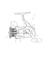
図1〜図3は、本発明の第1の実施形態に係る魚釣用リールの一例としての魚釣用スピニングリール1を示している。特に図1に示されるように、魚釣用スピニングリール1は、従来のものと同様に、ボディ部分2、ボディ部分2に回転自在に取り付けられた釣糸巻き取り用のハンドル3、ボディ部分2内に設けた伝動機構等を覆う蓋体4、ハンドル3の回転時にその回転トルクを伝動する図示しない伝動機構に接続されたロータ5、ロータ5の両側に形成され、リール本体1の前方に延在する一対の支持アーム8、支持アーム8の前端に設けられたベール支持部材やラインローラなどの公知の釣糸案内装置を備えており、かつ半環状のベール8aがラインローラを装着したベールアームやベールホルダー等のベール支持部材を介して釣糸巻取位置と釣糸放出位置との間で夫々反転自在に取り付けられている。
1 to 3 show a fishing spinning reel 1 as an example of a fishing reel according to a first embodiment of the present invention. In particular, as shown in FIG. 1, a fishing spinning reel 1 includes a body part 2, a fishing line winding handle 3 that is rotatably attached to the body part 2, and a body part 2. The cover 4 that covers the transmission mechanism and the like provided on the rotor 4, the rotor 5 that is connected to a transmission mechanism (not shown) that transmits the rotational torque when the handle 3 rotates, are formed on both sides of the rotor 5, and extend forward of the reel body 1. A pair of support arms 8, a bail support member provided at the front end of the support arm 8, and a known fishing line guide device such as a line roller, and a
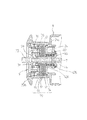
図2は図1の一部、すなわち、スプール部分を拡大して示した断面図である。図中、6はスプールであって、スプール軸7にドラグ装置9を介して遊嵌されている(具体的には、後述するように回転可能に軸支される)。スプール軸7は、リール本体1内に内蔵された摺動子やトラバースカムからなるトラバース装置(図示せず)により、ハンドル3の回転に連動して前後方向に進退自在にトラバース運動する。このスプール軸7の前端部には、図2に示すようにドラグ調整ノブ35内に軸方向移動可能に回り止め嵌合したナット36に螺合する螺合部7aが形成されている。ナット36は、ドラグ調整ノブ35に装着固定されるカップ状の保持体35a内に設けた螺旋バネ37のバネ力によってドラグ調整ノブ35側に圧接されている。スプール軸7の前部には、ピン44によってスプールメタル40が一体的に連結されており、このスプールメタル44の外周にカップ状で内周に凹凸部が形成されたバネ受91(発音体)が回り止め嵌合されている。そして、保持体35aに係止された環状バネ38の端部がバネ91の凹凸部に係合しており、ドラグ調整ノブ35を回転させることにより節度感のあるクリック音を発生するように構成されている。したがって、ドラグ調整ノブ35を左右いずれかに回すことでナット36をスプール軸7に対して進退させ、それによって螺旋バネ37のバネ力を調節し、ドラグ制動部材90のドラグ力を調節することができる。
FIG. 2 is an enlarged cross-sectional view of a part of FIG. 1, that is, a spool portion. In the figure, reference numeral 6 denotes a spool, which is loosely fitted to the
ここで、ドラグ制動部材90は、スプールメタル40に回り止め嵌合したバネ受91と、外周端に設けた折曲部をスプール6のスプール軸止部24の係止孔24aに係止しスプール6と一体に回転するドラグワッシャ92と、スプールメタル40に回り止め嵌合されたドラグワッシャ93と、バネ受91とドラグワッシャ92,93とスプール軸止部24との間にそれぞれ介挿された複数のライニングワッシャ94とから成っている。
Here, the
以上の構成において、釣糸の巻き取りは、ベール8a(図1)を糸巻き取り位置にしてハンドル3を回転して行なう。すなわち、ハンドル3を回すと歯車伝動機構などを介してロータ5が回転し、それに伴ってリール本体1内に設けた前記トラバース機構により、スプール軸7がリール本体1に対して往復動可能に前後動し、ドラグ機構9を介してスプール軸7に連結されたスプール6もリール本体1に対して前後動する。他方、ロータ5の回転により前記釣糸案内装置のベール8aがスプール6の周りを回転し、スプール6の糸巻胴部10に釣糸を巻回することで、釣糸はスプール6上に一端(前)側から他端(後)側に向かって順次巻回される。
In the above configuration, the fishing line is wound up by rotating the handle 3 with the
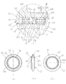
また、図2に示されるように、本実施形態において、回転部材としてのスプール6は、そのスプール軸支部24が非回転部材としての筒状のスプールメタル40(したがって、スプール軸7)上に2つの軸受42A,42Bを介して回転可能に支持されている。各軸受42A,42Bは、図3に明確に示されるように、スプール6(スプール軸支部24)と接触する外輪42aと、スプールメタル40に接触する内輪42bと、外輪42aと内輪42bとの間に介挿されて保持器(図示せず)により転動可能に保持されるコロ(転動体)とから成る。なお、軸受42A,42Bの両端には蓋部材42cがある。
As shown in FIG. 2, in the present embodiment, the spool 6 as the rotating member has a spool
また、これらの軸受42A,42Bは、水分がロータ5とスプール6との間の隙間からスプール6内部のドラグ装置(ドラグ機構)9へと浸入することを防止する防水機構を一体で備えている。具体的には、2つの軸受42A,42B間には、これらの軸受42A,42Bの内輪42b同士の間に挟持されるように弾性部材から成るシール部材60が配設される。このシール部材60は、ゴムやエラストマー樹脂などによって形成され、非回転部材であるスプールメタル40の外周面にシール状態で弾性的に嵌着する環状の本体部62と、この本体部62から径方向外側に延在してその端部64aが回転部材であるスプール6のスプール軸支部24の内周面にシール接触する延出部64とを有する。この場合、シール部材60の本体部62は、スプールメタル40がシール状態で挿通される内孔60aを有しており、その軸方向両端面62a,62bが軸受42A,42Bの内輪42bとシール状態で接触するとともに、その内周面62cがスプールメタル40の外周面とシール状態で接触する。
These bearings 42 </ b> A and 42 </ b> B are integrally provided with a waterproof mechanism that prevents moisture from entering the drag device (drag mechanism) 9 inside the spool 6 from the gap between the rotor 5 and the spool 6. . Specifically, a
このように、本実施形態によれば、シール部材60が2つの軸受42A,42B間に配設されているため、シール部材60と接触し得る水分は、一方の軸受(本実施形態では、軸受42B)を通過してその圧力が低下された水分となり、したがって、回転部材であるスプール6の軸支部分に浸入してきた水分がそのままの水圧で直接にシール部材60に接触することを防止できる。そのため、シール部材60に対する負荷が小さくなり、シール部材60の早期の損耗を防止でき、シール部材60の耐久性を高めることができる(長期にわたって十分な防水性能を確保できる)。本実施形態において、軸受42A,42Bの内外輪42a,42bと回転部材および非回転部材であるスプールメタル40およびスプール軸支部24との間の隙間は非常に小さく、また、軸受42A,42B内にはコロ42d、保持器(図示せず)、蓋部材41cなどの間の隙間にオイルが充填されているため、軸受42A,42Bの流水抵抗は大きく、したがって、軸受42Bを通過する水分の圧力低下は大きい。そのため、水分が軸受42Bを介してシール部材60に接触する本実施形態の構成は、防水性能およびシール部材の耐性を高める上で極めて有益である。
As described above, according to the present embodiment, since the
また、本実施形態では、2つの軸受42A,42B間の空間にシール部材60を配設する構造を成すため、本実施形態のように回転部材であるスプール6が回転軸であるスプール軸7に対して傾かないように2つの軸受42A,42Bが互いに離間される構造では、軸受42A,42B間の空間を有効利用してシール部材60のための新たなスペースを確保せずに済み、有益である(省スペース化に寄与できる)。
In the present embodiment, since the
また、このように弾性部材から成るシール部材60が2つの軸受42A,42B間に配設されていると、リールを落下させた場合など大きな衝撃がかかった際に、シール部材60の弾性変形によって軸受42A,42B間の軸方向距離を変えることができるため、軸受42A,42B等が破損し難いという利点も得られる。
In addition, when the
また、シール部材60は、スプールメタル40の周面にシール状態で嵌着する環状の本体部62と、この本体部62から径方向に延在してその端部がスプール6のスプール軸支部24の周面にシール接触する延出部64とを有する弾性部材として形成されているため、回転部材であるスプール6に対して大きな回転抵抗を与えることなく、スラスト方向の防水(本体部62の内周面62cとスプールメタル40の外周面との間の防水)およびラジアル方向の防水(内輪42bの端面と本体部62の両端面62a,62bとの間の防水、および、延出部64の端部64aとスプール軸支部24の内周面との間の防水)を1部品で実現することができ、部品点数を削減してリールの小型化に寄与できる。
更に、本実施形態では、互いに離間する2つの軸受42A,42Bによってスプール6が回転可能に支持されるため、スプール6の回転性能を高めることができるとともに、スプール6がスプール軸7に対して傾かないようにしてスプール6の回転安定性を確保することができる。
The
Further, in the present embodiment, the spool 6 is rotatably supported by the two
また、本実施形態によれば、シール部材60の本体部62は、2つの軸受42A,42Bの内輪42b同士の間に挟持された状態でスプールメタル40の外周面に弾性的に嵌着するため、すなわち、シール部材60が弾性締め付け力を利用してスプールメタル40の外周面にシール状態で圧着するため、スプールメタル40に対するシール効果が高まることは無論のこと、軸受内輪42bに対するシール効果も高めることができ、スラスト方向の防水(本体部62の内周面62cとスプールメタル40の外周面との間の防水)およびラジアル方向の防水(内輪42bの端面と本体部62の両端面62a,62bとの間の防水)を更に安定して確実に図ることができる。
Further, according to the present embodiment, the
図4は本発明の第2の実施形態を示している。図示のように、本実施形態では、シール部材60の形状が第1の実施形態と若干異なっており、それ以外の構成は第1の実施形態と同一である。
FIG. 4 shows a second embodiment of the present invention. As illustrated, in this embodiment, the shape of the
すなわち、本実施形態では、2つの軸受42A,42Bの内輪42bと接触する本体部62の両端面62a,62bに、2つの軸受42A,42B間で本体部62を挟持する軸方向の挟持力をスプール軸支部24の内周面に延出部64の端部64aを接触させる径方向の接触力へと変換するための軸方向延在部が設けられている。具体的に、本実施形態において、前記軸方向延在部は、延出部64の延在方向と反対側の径方向に向かって(すなわち、径方向内側に向かって)本体部62の軸方向寸法を徐々に拡大させるテーパ面62a’,62b’として形成される。すなわち、この構成では、2つの軸受42A,42B間で本体部62を挟持する(若干押し潰す)ことにより、テーパ面62a’,62b’の作用で本体部62が径方向に弾性的に変形して延出部64が径方向外側に延びるように立ち上がって延出部64の端部64aがスプール軸支部24の内周面にシール状態で圧接するようになる。
That is, in the present embodiment, the axial holding force for holding the
このように、本実施形態によれば、前記軸方向延在部の作用により、2つの軸受42A,42B間にシール部材60を挟持させるだけで回転部材(スプール軸支部24)および非回転部材(スプールメタル40)の両方のシールを確保できる。また、テーパ面62a’,62b’によって軸方向の挟持力を径方向の接触力へと効率的に変換できる。
As described above, according to the present embodiment, the rotating member (spool shaft support portion 24) and the non-rotating member (spindle member 24) are simply held between the two
図5は本発明の第3の実施形態を示している。図示のように、本実施形態では、シール部材60の前記軸方向延在部が軸方向に半球状に突出する突出部69として形成されており、それ以外の構成は第1の実施形態と同一である。
FIG. 5 shows a third embodiment of the present invention. As shown in the figure, in the present embodiment, the axially extending portion of the
このような構成によれば、軸方向延在部の簡単な形状により軸方向の挟持力を径方向の接触力へと変換でき、有益である。 According to such a configuration, the axial clamping force can be converted into the radial contact force by a simple shape of the axially extending portion, which is beneficial.
なお、本発明は、前述した実施形態に限定されず、その要旨を逸脱しない範囲で種々変形して実施できる。例えば、前述した実施形態では本発明がスピニングリールに適用されているが、本発明は両軸受型リールなどの他のリールにも適用できる。また、前述した実施形態ではシール部材60が軸受42A,42Bの内輪42b間で挟持されているが、シール部材60が軸受42A,42Bの外輪42a同士の間で挟持されてもよい。その場合には、本体部62が回転部材であるスプール6のスプール軸支部24の周面にシール状態で嵌着し、延出部64の端部64aがが非回転部材であるスプールメタル40の周面にシール接触してもよい。
The present invention is not limited to the above-described embodiments, and can be implemented with various modifications without departing from the scope of the invention. For example, in the embodiment described above, the present invention is applied to a spinning reel, but the present invention can also be applied to other reels such as a double bearing type reel. In the embodiment described above, the
1 魚釣用リール
5 ロータ
6 スプール(回転部材)
24 スプール軸支部(回転部材)
40 スプールメタル(非回転部材)
42A,42B 軸受
60 シール部材
62 本体部
62a’,62b’ テーパ面
64 延出部
69 突出部
1 Fishing Reel 5 Rotor 6 Spool (Rotating Member)
24 Spool shaft support (rotating member)
40 Spool metal (non-rotating member)
42A,
Claims (4)
前記2つの軸受間には、これらの軸受の内輪または外輪同士の間に挟持されるように弾性部材から成るシール部材が配設され、
前記シール部材は、回転部材および非回転部材のうちの一方の周面にシール状態で嵌着する環状の本体部と、この本体部から径方向に延在してその端部が回転部材および非回転部材のうちの他方の周面にシール接触する延出部とを有することを特徴とする魚釣用リール。 A fishing reel in which a rotating member is rotatably supported with respect to a non-rotating member via two bearings,
Between the two bearings, a seal member made of an elastic member is disposed so as to be sandwiched between inner rings or outer rings of these bearings,
The seal member includes an annular main body portion that is fitted in a sealed state on one circumferential surface of the rotating member and the non-rotating member; A fishing reel comprising: an extending portion in sealing contact with the other peripheral surface of the rotating member.
前記シール部材は、水分が前記ロータと前記スプールとの間の隙間からスプール内部のドラグ機構へと浸入することを防止することを特徴とする請求項1に記載の魚釣用リール。 The rotor which has a fishing line guide part is rotationally driven by a rotation operation of a handle provided on the reel body, and a structure for winding the fishing line around the spool is formed.
The fishing reel according to claim 1, wherein the seal member prevents moisture from entering a drag mechanism inside the spool from a gap between the rotor and the spool.
Priority Applications (1)
| Application Number | Priority Date | Filing Date | Title |
|---|---|---|---|
| JP2010288227A JP5606900B2 (en) | 2010-12-24 | 2010-12-24 | Fishing reel |
Applications Claiming Priority (1)
| Application Number | Priority Date | Filing Date | Title |
|---|---|---|---|
| JP2010288227A JP5606900B2 (en) | 2010-12-24 | 2010-12-24 | Fishing reel |
Publications (2)
| Publication Number | Publication Date |
|---|---|
| JP2012135230A true JP2012135230A (en) | 2012-07-19 |
| JP5606900B2 JP5606900B2 (en) | 2014-10-15 |
Family
ID=46673244
Family Applications (1)
| Application Number | Title | Priority Date | Filing Date |
|---|---|---|---|
| JP2010288227A Active JP5606900B2 (en) | 2010-12-24 | 2010-12-24 | Fishing reel |
Country Status (1)
| Country | Link |
|---|---|
| JP (1) | JP5606900B2 (en) |
Cited By (3)
| Publication number | Priority date | Publication date | Assignee | Title |
|---|---|---|---|---|
| CN110731316A (en) * | 2018-07-19 | 2020-01-31 | 株式会社岛野马来西亚配件厂有限公司 | Spinning wheel type winder |
| CN113016734A (en) * | 2019-12-24 | 2021-06-25 | 株式会社岛野马来西亚配件厂有限公司 | Fishing reel for fishing |
| JP7377027B2 (en) | 2019-08-29 | 2023-11-09 | 株式会社ジェイテクトフルードパワーシステム | Swash plate type axial piston pump/motor |
Citations (5)
| Publication number | Priority date | Publication date | Assignee | Title |
|---|---|---|---|---|
| JPS63152920U (en) * | 1987-03-28 | 1988-10-06 | ||
| JPH11239437A (en) * | 1998-02-26 | 1999-09-07 | Daiwa Seiko Inc | Spinning reel for fishing |
| JP2001275533A (en) * | 2000-03-30 | 2001-10-09 | Daiwa Seiko Inc | Spinning reel for fishing |
| JP2002345367A (en) * | 2001-05-30 | 2002-12-03 | Daiwa Seiko Inc | Reel for fishing |
| JP2007202416A (en) * | 2006-01-31 | 2007-08-16 | Daiwa Seiko Inc | Fishing reel |
-
2010
- 2010-12-24 JP JP2010288227A patent/JP5606900B2/en active Active
Patent Citations (5)
| Publication number | Priority date | Publication date | Assignee | Title |
|---|---|---|---|---|
| JPS63152920U (en) * | 1987-03-28 | 1988-10-06 | ||
| JPH11239437A (en) * | 1998-02-26 | 1999-09-07 | Daiwa Seiko Inc | Spinning reel for fishing |
| JP2001275533A (en) * | 2000-03-30 | 2001-10-09 | Daiwa Seiko Inc | Spinning reel for fishing |
| JP2002345367A (en) * | 2001-05-30 | 2002-12-03 | Daiwa Seiko Inc | Reel for fishing |
| JP2007202416A (en) * | 2006-01-31 | 2007-08-16 | Daiwa Seiko Inc | Fishing reel |
Cited By (4)
| Publication number | Priority date | Publication date | Assignee | Title |
|---|---|---|---|---|
| CN110731316A (en) * | 2018-07-19 | 2020-01-31 | 株式会社岛野马来西亚配件厂有限公司 | Spinning wheel type winder |
| CN110731316B (en) * | 2018-07-19 | 2023-03-03 | 株式会社岛野马来西亚配件厂有限公司 | Spinning wheel type winder |
| JP7377027B2 (en) | 2019-08-29 | 2023-11-09 | 株式会社ジェイテクトフルードパワーシステム | Swash plate type axial piston pump/motor |
| CN113016734A (en) * | 2019-12-24 | 2021-06-25 | 株式会社岛野马来西亚配件厂有限公司 | Fishing reel for fishing |
Also Published As
| Publication number | Publication date |
|---|---|
| JP5606900B2 (en) | 2014-10-15 |
Similar Documents
| Publication | Publication Date | Title |
|---|---|---|
| JP4943406B2 (en) | Fishing reel | |
| US9091350B2 (en) | Spinning reel waterproofing member and spinning reel using the same | |
| JP5749215B2 (en) | Fishing reel | |
| JP5677211B2 (en) | Fishing reel | |
| JP5961290B2 (en) | Fishing reel with drag assembly | |
| JP2013179882A (en) | Spinning reel waterproofing member and spinning reel using the same | |
| JP5606900B2 (en) | Fishing reel | |
| JP2014226071A (en) | Spinning reel | |
| JP6467218B2 (en) | Double bearing reel | |
| TWI684402B (en) | Wire wheel assembly and fishing line guiding mechanism | |
| JP5330326B2 (en) | Fishing reel | |
| JP6261973B2 (en) | Spinning reel | |
| CN111700040B (en) | Reel for fishing | |
| JP2014528562A5 (en) | ||
| CN106172291B (en) | Dual-bearing fishing reel | |
| JP5613426B2 (en) | Fishing spinning reel | |
| JP5254823B2 (en) | Fishing reel | |
| JP6261971B2 (en) | Spinning reel | |
| JP2020099255A (en) | Line roller | |
| CN102480933B (en) | Rotation-restricting device for a fly reel spool | |
| TWI819176B (en) | Reels for fishing tackle | |
| JP5300999B2 (en) | Fishing reel | |
| JP2010273618A (en) | Spinning reel for fishing | |
| JP6261972B2 (en) | Spinning reel | |
| CN108782487A (en) | Rotary extrusion type spinning reel |
Legal Events
| Date | Code | Title | Description |
|---|---|---|---|
| A621 | Written request for application examination |
Free format text: JAPANESE INTERMEDIATE CODE: A621 Effective date: 20130205 |
|
| A977 | Report on retrieval |
Free format text: JAPANESE INTERMEDIATE CODE: A971007 Effective date: 20130827 |
|
| A131 | Notification of reasons for refusal |
Free format text: JAPANESE INTERMEDIATE CODE: A131 Effective date: 20130919 |
|
| TRDD | Decision of grant or rejection written | ||
| A01 | Written decision to grant a patent or to grant a registration (utility model) |
Free format text: JAPANESE INTERMEDIATE CODE: A01 Effective date: 20140806 |
|
| A61 | First payment of annual fees (during grant procedure) |
Free format text: JAPANESE INTERMEDIATE CODE: A61 Effective date: 20140827 |
|
| R150 | Certificate of patent or registration of utility model |
Ref document number: 5606900 Country of ref document: JP Free format text: JAPANESE INTERMEDIATE CODE: R150 |
|
| R250 | Receipt of annual fees |
Free format text: JAPANESE INTERMEDIATE CODE: R250 |
|
| R250 | Receipt of annual fees |
Free format text: JAPANESE INTERMEDIATE CODE: R250 |
|
| R250 | Receipt of annual fees |
Free format text: JAPANESE INTERMEDIATE CODE: R250 |
|
| R250 | Receipt of annual fees |
Free format text: JAPANESE INTERMEDIATE CODE: R250 |
|
| R250 | Receipt of annual fees |
Free format text: JAPANESE INTERMEDIATE CODE: R250 |
|
| R250 | Receipt of annual fees |
Free format text: JAPANESE INTERMEDIATE CODE: R250 |
|
| R250 | Receipt of annual fees |
Free format text: JAPANESE INTERMEDIATE CODE: R250 |