JP2012134367A - Sheath tube and wire harness - Google Patents
Sheath tube and wire harness Download PDFInfo
- Publication number
- JP2012134367A JP2012134367A JP2010286004A JP2010286004A JP2012134367A JP 2012134367 A JP2012134367 A JP 2012134367A JP 2010286004 A JP2010286004 A JP 2010286004A JP 2010286004 A JP2010286004 A JP 2010286004A JP 2012134367 A JP2012134367 A JP 2012134367A
- Authority
- JP
- Japan
- Prior art keywords
- electric wire
- voltage
- wire
- sheath tube
- insertion space
- Prior art date
- Legal status (The legal status is an assumption and is not a legal conclusion. Google has not performed a legal analysis and makes no representation as to the accuracy of the status listed.)
- Granted
Links
Images


Landscapes
- Insulated Conductors (AREA)
- Shielding Devices Or Components To Electric Or Magnetic Fields (AREA)
Abstract
Description
この発明は、電線を覆って保護する鞘管及びその鞘管を用いたワイヤーハーネスに関し、例えば、電線の高周波電流による電磁ノイズが周囲に悪影響を与えることを防止するシールド機能を備えた鞘管及びその鞘管を用いたワイヤーハーネスに関する。 The present invention relates to a sheath tube that covers and protects an electric wire and a wire harness using the sheath tube, for example, a sheath tube having a shield function for preventing electromagnetic noise due to high-frequency current of the electric wire from adversely affecting the surroundings, and The present invention relates to a wire harness using the sheath tube.
一般に、電気自動車のインバータ装置やモータなどの機器間に接続する電線の中でも、特に、高圧電線は、高周波電流が流れることや機器からの伝播により発生する電磁ノイズの影響が大きいことが知られている。
よって、ノイズ源である高圧電線を、シールド部材を備えたシールド電線として構成することで、他の機器や電線に対して悪影響を及ぼさないように、発生するノイズを遮断していた。
さらに、これら複数本のシールド電線の外周を、合成樹脂製のプロテクタや、特許文献1に開示の蛇腹管で覆うことで、電線を外的損傷から保護していた。
すなわち、従来のワイヤーハーネスは、電磁ノイズに対するシールド機能と外的負荷に対する保護機能とを確保するため、それぞれ別々の部材を備えた構成であるため、部品点数が多くなり、その分、配索スペースやコストが嵩むとともに、重量化するという問題があった。
In general, among electric wires connected between devices such as inverter devices and motors of electric vehicles, particularly high-voltage wires are known to have a large influence of high-frequency current and electromagnetic noise generated by propagation from the devices. Yes.
Therefore, the noise which generate | occur | produces was interrupted | blocked by comprising the high voltage electric wire which is a noise source as a shielded electric wire provided with the shield member so that it may not have a bad influence with respect to another apparatus or electric wire.
Further, the outer periphery of the plurality of shielded wires is covered with a protector made of synthetic resin or the bellows tube disclosed in Patent Document 1, thereby protecting the wires from external damage.
In other words, the conventional wire harness has a configuration in which each member is provided in order to secure a shielding function against electromagnetic noise and a protection function against an external load. In addition, the cost increases and the weight increases.
このような問題に対して特許文献2では、複数本のノンシールド電線を金属製のパイプ内に挿通することで、これらノンシールド電線を一括で保護した状態で電磁ノイズをシールドする導電路が提案されている。 For such a problem, Patent Document 2 proposes a conductive path that shields electromagnetic noise in a state where these non-shielded wires are collectively protected by inserting a plurality of non-shielded wires into a metal pipe. Has been.
これにより、従来より、シールド機能と保護機能とを別々の部材で構成していたものを、これら機能を兼ね備えた上述したような金属管を用いることで部品点数を削減でき、配索スペースの省スペース化、コストダウン、及び軽量化が期待できる。 As a result, it has been possible to reduce the number of parts by using a metal pipe having the functions described above, which has a shield function and a protection function, as described above. Space saving, cost reduction, and weight reduction can be expected.
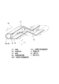
ところで、最近では、車両における部品の搭載位置関係の改良や、ワイヤーハーネスの配索スペースの削減などの様々な理由により、図5に示すように、高圧電線20Hと低圧電線20L’とを同じ金属管101に挿通して同一経路でまとめて配索するタイプのワイヤーハーネス100が増加している。
By the way, recently, for various reasons such as improvement of the mounting position relationship of parts in a vehicle and reduction of wiring harness wiring space, as shown in FIG. 5, the high-voltage
しかし、高圧電線20Hと低圧電線20L’とが混在した複数本の電線20を一括して金属管101の1つの内部空間に挿通した構成の従来のワイヤーハーネス100の場合、低圧電線20L’は、ノイズ源である高圧電線20Hからの電磁ノイズの影響を受けるため、ノイズ対策として、導体の外周にシールド部材として例えば、編組物23を被覆した構成のシールド電線を使用する必要があった。
However, in the case of the
このように、高圧電線20Hと低圧電線20L’とが混在した複数本の電線20を金属製のパイプに挿通する場合には、特許文献2における導電路においても、上述と同様に電磁ノイズの影響を受けるという問題が生じることが想定される。
As described above, when a plurality of
すなわち、ノイズ源である高圧電線20Hと低圧電線20L’とをまとめて同じ金属管101に挿通して同一経路で配策する場合、低圧電線20L’を含めた全ての電線20のノンシールド化を実現できず、ノイズ源である高圧電線20H、或いはノイズの影響を受ける低圧電線20L’をシールド電線として構成する必要があり、十分な配索スペースやコストダウンの削減や、軽量化を図れなかった。
That is, when the high-voltage
また、複数本の電線を同じ金属管に挿入しようとした場合、金属管内において電線が撓むなどして互いに接触するため、金属管への挿入作業に手間を要するという問題もあった。 In addition, when trying to insert a plurality of electric wires into the same metal tube, there is a problem that the operation of inserting the metal tube into the metal tube is troublesome because the electric wires are bent and contact each other in the metal tube.
そこでこの発明は、高圧電線と低圧電線とを同一経路で配索する配索形態において、低圧電線がノイズ源である高圧電線から電磁ノイズの影響を受けず、低圧電線を含めた全ての電線のノンシールド化を図ることができ、結果的に、配索スペースの削減、軽量化、コストダウンを図ることができ、また、複数本の電線でもスムーズな挿入作業ができる鞘管及びワイヤーハーネスの提供を目的とする。 Therefore, the present invention is a wiring configuration in which the high-voltage wire and the low-voltage wire are routed in the same route, and the low-voltage wire is not affected by electromagnetic noise from the high-voltage wire that is a noise source, and all the wires including the low-voltage wire are not affected. Providing a sheath tube and wire harness that can be non-shielded, resulting in a reduction in wiring space, weight reduction, cost reduction, and smooth insertion work even with multiple wires. With the goal.
この発明は、電磁ノイズ遮断用のシールド部材で形成するとともに、複数本の電線の挿通を許容する電線挿通空間を鞘管本体の内部に有する鞘管であって、前記電線挿通空間における管軸方向に対して直交する直交断面において、電磁ノイズを発生する高電圧電線の挿通を許容する高電圧用挿通空間と、低電圧電線の挿通を許容する低電圧用挿通空間とに区分けするとともに、前記高電圧電線と前記低電圧電線とを隔離する隔壁を、前記管軸方向に沿って前記電線挿通空間に形成し、前記隔壁を、前記シールド部材で構成したことを特徴とする。 The present invention is a sheath tube formed with a shield member for blocking electromagnetic noise and having a wire insertion space inside a sheath tube body that allows insertion of a plurality of wires, and the tube axis direction in the wire insertion space The high-voltage insertion space that allows insertion of high-voltage wires that generate electromagnetic noise and the low-voltage insertion space that allows insertion of low-voltage wires in the orthogonal cross section orthogonal to the The partition which isolates a voltage electric wire and the said low voltage electric wire is formed in the said electric wire insertion space along the said tube-axis direction, The said partition was comprised with the said shield member, It is characterized by the above-mentioned.
上述した構成により、高圧電線と低圧電線とを同一経路で配索する配索形態において、低圧電線がノイズ源である高圧電線から電磁ノイズの影響を受けず、低圧電線を含めた全ての電線のノンシールド化を図ることができ、結果的に、配索スペースの削減、軽量化、コストダウンを図ることができる。 With the configuration described above, in the routing configuration in which the high-voltage wire and the low-voltage wire are routed in the same route, the low-voltage wire is not affected by electromagnetic noise from the high-voltage wire that is the noise source, and all the wires including the low-voltage wire are not affected. Non-shielding can be achieved, and as a result, the wiring space can be reduced, the weight can be reduced, and the cost can be reduced.
詳しくは、電磁ノイズを発生する高電圧電線と、高電圧電線から発生する電磁ノイズの影響を受ける低電圧電線とからなる複数本の電線を、鞘管本体内部の電線挿通空間にまとめて挿通しても、前記電線挿通空間において、シールド部材で構成した隔壁によって、前記高電圧電線に対して前記低電圧電線を隔離したため、低電圧電線をノンシールド電線で構成したものを用いても、高電圧電線から発生する電磁ノイズの影響を受けることを防ぐことができる。 Specifically, multiple wires consisting of a high-voltage wire that generates electromagnetic noise and a low-voltage wire that is affected by the electromagnetic noise generated from the high-voltage wire are inserted into the wire insertion space inside the sheath body. However, in the wire insertion space, the low-voltage wire is isolated from the high-voltage wire by the partition wall made of a shield member. It is possible to prevent being affected by electromagnetic noise generated from the electric wire.
従って、鞘管に挿通する全ての電線をノンシールド電線としたノンシールド化の実現を図ることができ、同一経路で配策する配索スペースの削減、軽量化、及び、コストダウンを図ることができる。 Therefore, it is possible to realize non-shielding by making all the wires inserted into the sheath tube into non-shielded wires, and to reduce the wiring space to be routed in the same route, to reduce the weight, and to reduce the cost. it can.
さらに、上述した構成により、複数本の電線でも鞘管に対してスムーズな挿入作業を行うことができる。 Furthermore, with the above-described configuration, even a plurality of electric wires can be smoothly inserted into the sheath tube.
詳しくは、電線挿通空間を隔壁によって高電圧用挿通空間と低電圧用挿通空間とに区分けすることにより、同一空間に挿入する電線の本数を低減することができる。このため、前記電線挿通空間において、撓んだ電線同士が互いに接触し合う機会を低減でき、複数本の電線であっても鞘管に対してスムーズに挿入することができる。 Specifically, the number of wires inserted into the same space can be reduced by dividing the wire insertion space into a high voltage insertion space and a low voltage insertion space by a partition wall. For this reason, in the said electric wire insertion space, the opportunity for the bent electric wires to mutually contact can be reduced, and even if it is a several electric wire, it can insert smoothly with respect to a sheath pipe.
この発明の態様として、前記電線挿通空間の前記直交断面を、複数の前記電線の並列配置を許容する断面形態で構成し、前記隔壁を、前記高電圧電線と前記低電圧電線との間に配置することができる。 As an aspect of the present invention, the orthogonal cross section of the wire insertion space is configured in a cross-sectional form allowing a plurality of the wires to be arranged in parallel, and the partition is disposed between the high-voltage wire and the low-voltage wire. can do.
上述した構成によれば、前記電線挿通空間の前記直交断面を、複数の前記電線の並列配置を許容する断面形態で構成することで、例えば、前記電線挿通空間の前記直交断面が円形状の断面形態の場合と比較して鞘管本体の薄肉化を図ることができるため、車体に取り付けたとき嵩張らず、また、取り付け易い形態とすることができる。 According to the configuration described above, by configuring the orthogonal cross section of the wire insertion space in a cross-sectional form that allows parallel arrangement of a plurality of the electric wires, for example, the orthogonal cross section of the wire insertion space is a circular cross section. Since the thickness of the sheath tube main body can be reduced as compared with the case of the form, it is not bulky when attached to the vehicle body and can be easily attached.
またこの発明の態様として、前記鞘管本体と前記隔壁とを押し出し成形により一体に構成することができる。 Moreover, as an aspect of this invention, the said sheath tube main body and the said partition can be integrally comprised by extrusion molding.
上述した構成によれば、例えば、前記鞘管本体と前記隔壁とを別体で構成した場合のように、前記鞘管本体と前記隔壁とを別々に形成した後で、互いに一体に取り付けるといった手間を必要とせず、押し出し成形により、前記鞘管本体と前記隔壁とを一体に構成した鞘管を一気に形成でき、大量生産も可能となる。 According to the above-described configuration, for example, when the sheath tube main body and the partition wall are configured separately, it is troublesome to attach the sheath tube body and the partition wall separately after being formed separately. Therefore, a sheath tube in which the sheath tube body and the partition wall are integrally formed can be formed at a stretch by extrusion molding, and mass production is also possible.
またこの発明の態様として、前記シールド部材を金属材料で形成することができる。
上記構成によれば、前記シールド部材を金属材料で形成することにより、優れたシールド機能を発揮することができるとともに、強度、耐熱性に優れるため、外的負荷に対して優れた保護機能を確保することができる。さらに、熱伝導性に優れるため、内部に熱が篭ることを回避でき、管の内側と外側との優れた均熱機能を確保することができる。さらにまた、金属材料の中には、材料供給性が安定した材料も多いため、大量生産にも適している。
As an aspect of the present invention, the shield member can be formed of a metal material.
According to the above configuration, by forming the shield member from a metal material, an excellent shield function can be exhibited, and since the strength and heat resistance are excellent, an excellent protection function against an external load is ensured. can do. Furthermore, since it is excellent in thermal conductivity, heat can be prevented from being generated inside, and an excellent heat equalizing function between the inside and outside of the tube can be ensured. Furthermore, since many metal materials have stable material supply properties, they are suitable for mass production.
またこの発明の態様として、前記隔壁を、編組物で構成することができる。
編組物は、変形性、屈曲性に優れるため、前記隔壁をこのような編組物で構成することによって、例えば、配策経路に屈曲部分を有する場合においても、その屈曲部分の形状に対応して屈曲させて配策することができる。
なお、前記編組物は、例えば、金属線などの線材を編み上げた構成であり、例えば、銅または銅合金に錫メッキ(以下において、Snメッキとする)を施した導体による編組みや、銅または銅合金にニッケルメッキ(以下において、Niメッキとする)を施した導体による編組みとすることができる。
Moreover, as an aspect of the present invention, the partition wall can be formed of a braid.
Since the braid is excellent in deformability and bendability, by configuring the partition wall with such a braid, for example, even when the routing path has a bent portion, it corresponds to the shape of the bent portion. It can be bent and routed.
The braided material has, for example, a configuration in which a wire such as a metal wire is knitted. For example, a braid made of a conductor in which copper or copper alloy is tin-plated (hereinafter referred to as Sn plating), or copper or copper. It can be a braid made of a conductor obtained by applying nickel plating (hereinafter referred to as Ni plating) to the alloy.
またこの発明は、上述した鞘管と、前記鞘管における前記高電圧用挿通空間に挿通する高圧用電線と、前記鞘管における前記低電圧用挿通空間に挿通する低圧用電線とで構成し、前記低圧用電線を低圧用ノンシールド電線で構成したワイヤーハーネスであることを特徴とする。 Further, the present invention comprises the above-described sheath tube, a high-voltage wire inserted into the high-voltage insertion space in the sheath tube, and a low-voltage wire inserted into the low-voltage insertion space in the sheath tube, The low-voltage electric wire is a wire harness composed of a low-voltage non-shielded electric wire.
この発明により、高圧電線と低圧電線とを同一経路で配索する配索形態において、低圧電線がノイズ源である高圧電線から電磁ノイズの影響を受けず、低圧電線を含めた全ての電線のノンシールド化を図ることができ、結果的に、配索スペースの削減、軽量化、コストダウンを図ることができ、また、複数本の電線でもスムーズな挿入作業ができる鞘管及びワイヤーハーネスを提供することができる。 According to the present invention, in the wiring configuration in which the high-voltage wire and the low-voltage wire are routed in the same route, the low-voltage wire is not affected by electromagnetic noise from the high-voltage wire that is a noise source, and all wires including the low-voltage wire are non-wired. Provided with a sheath tube and a wire harness that can be shielded, resulting in a reduction in wiring space, weight reduction, cost reduction, and smooth insertion work even with multiple wires. be able to.
この発明の一実施例を以下図面に基づいて説明する。
(第1実施形態)
第1実施形態のワイヤーハーネス10Aは、車両、特に電気自動車のバッテリ、モータなどの装置間を電気的に接続して、高周波電流を流すのに適した構成であり、例えば、車両床下に配策している。
An embodiment of the present invention will be described below with reference to the drawings.
(First embodiment)
The
ワイヤーハーネス10Aは、図示しない車両床下の定められた取付位置の凹凸形状に応じた適合形状で、該取付位置に対して図示しないクランプによって取り付けている。
The
すなわち、ワイヤーハーネス10Aは、図1(a),(b)、及び図2に示すように、前記適合形状に形作られた形状となるよう管軸方向Xにおいて適宜の屈曲部分を形成している。なお、図1(a)は、ワイヤーハーネス10Aの管軸方向Xにおける一部分、詳しくは、屈曲部分としての第1屈曲部33、及び第2屈曲部34、並びにこれら屈曲部分の周辺部分を一部断面で示した外観図である。図1(b)は図1(a)のA−A線端面図である。図2は、図1で示した鞘管30の構成説明図であり、鞘管本体32の周方向の一部を省略して示した鞘管30の構成説明図である。また、以下の説明においては、図1中のX方向、W方向、T方向のそれぞれを、ワイヤーハーネス10Aの管軸方向X、幅方向W、厚み方向Tとして説明する。
That is, 10 A of wire harnesses form the appropriate bending part in the pipe-axis direction X so that it may become the shape shape | molded in the said conformation shape, as shown to FIG. 1 (a), (b) and FIG. . FIG. 1A shows a part of the
ワイヤーハーネス10Aは、3本の電線20と、電磁ノイズ遮断機能を有するシールド機能、および外的負荷に対しての保護機能を兼ね備えたアルミ二ウム合金製の鞘管30とで構成している。
10A of wire harnesses are comprised with the three
3本の電線20のうち、2本の電線20は、高周波電流に対応して定格電流が高く、電磁ノイズを発生する高圧用電線20Hとして構成し、1本の電線20は、高圧用電線20Hよりも定格電流が低く、高圧用電線20Hからの電磁ノイズの影響を受け易い低圧用電線20Lとして構成している。高圧用電線20Hと低圧用電線20Lとは、いずれも、金属線の編組物や、金属箔などのシールド部材で導体21の外周を覆っていないシールドレス電線で構成している。
なお、電線20は、銅合金などの金属性の導体21の外周をポリ塩化ビニルなどの合成樹脂成性の絶縁被覆22で被覆した構成である。
Of the three
The
鞘管30は、管外周面を構成する鞘管本体32と、鞘管本体32の内部に有する電線挿通空間40を高電圧用挿通空間40Hと低電圧用挿通空間40Lとに区分けする隔壁31とで構成し、押し出し成形により鞘管本体32と隔壁31とを一体に構成している。
The
前記鞘管本体32は、管軸方向Xに対して直交する直交断面が厚み方向Tに対して幅方向Wが長い長孔状の直交断面で形成している。換言すると、鞘管本体32の内部に有する電線挿通空間40は、図1(b)に示すように、3本の電線20が幅方向Wに沿って並列配置した状態での挿通を許容する長孔形状の直交断面で形成している。
In the sheath tube
なお、長孔形状とは、厚み方向Tの長さに対して長い幅方向Wにおける両端側が、幅方向Wにおいて互いの内周面が対向する半円弧形状であり、これら一対の半円弧形状の厚み方向Tの一方の端部同士を幅方向Wに沿って直線状に結ぶとともに、厚み方向Tの他方の端部同士を幅方向Wに沿って直線状に結んだ形状である。 In addition, the long hole shape is a semicircular arc shape in which both end sides in the width direction W that are long with respect to the length in the thickness direction T are opposed to each other in the width direction W, and the pair of semicircular arc shapes. One end of the thickness direction T is linearly connected along the width direction W, and the other end of the thickness direction T is linearly connected along the width direction W.
前記隔壁31は、高電圧用挿通空間40Hと低電圧用挿通空間40Lとの体積比が略2:1となるよう厚み方向Tと一致する方向に沿った直線状の形態で電線挿通空間40を区分けするように配設している。
The
これにより、隔壁31は、高電圧用挿通空間40Hに挿通した2本の高電圧電線20Hと、低電圧用挿通空間40Lに挿通した1本の低電圧電線20Lとを隔離する。
Thereby, the
なお、高電圧用挿通空間40Hは、2本の高電圧電線20Hを幅方向Wにおいて互いに隣接させて並列配置した状態での挿通を許容する直交断面で形成している。低電圧用挿通空間40Lは、1本の低電圧電線20Lを、並列配置した2本の高電圧電線20Hに対して、隔壁31を介在させて並列配置した状態での挿通を許容する直交断面で形成している。
Note that the high-
また、隔壁31は、鞘本体の管軸方向Xにおいて第1屈曲部33、及び第2屈曲部34のそれぞれの屈曲形状に対応して屈曲し、高電圧用挿通空間40Hにおける前記直交断面における高電圧用挿通空間40Hと低電圧用挿通空間40Lとの空間比が前記管軸方向Xの全長に亘って一定となるよう形成している。
In addition, the
以上により、ワイヤーハーネス10Aは、低圧用電線20Lと高圧用電線20Hとを鞘管30によって保護した状態で同一経路に配策することができ、以下のような様々な作用、効果を奏することができる。
鞘管30は、高電圧電線20Hに対して低電圧電線20Lを隔離する金属製の隔壁31を、前記管軸方向Xに沿って電線挿通空間40に形成しているため、高電圧電線20Hと低電圧電線20Lとからなる複数本の電線20を、鞘管本体32の内部の電線挿通空間40にまとめて挿通したとき、電線挿通空間40において、シールド機能を有するアルミ合金製の隔壁31によって、高電圧電線20Hと低電圧電線20Lとを互いに隔離した状態で挿通することができる。
As described above, the
The
よって、高電圧電線20Hと、該高電圧電線20Hから発生する電磁ノイズの影響を受ける低電圧電線20Lとが混在する全ての電線20をノンシールド化し、これら複数のノンシールド電線を同一経路で配策しても電磁ノイズの影響を受けることを防ぐことができる。
Therefore, all the
従って、鞘管30に挿通する全ての電線20をノンシールド電線20としたノンシールド化の実現を図ることができ、同一経路で配策した複数本の電線20の軽量化、及び、コストダウンを図ることができる。
Accordingly, it is possible to realize non-shielding by making all the
また、鞘管30は、隔壁31により、電線挿通空間40を、管軸方向Xに対して直交する直交断面において、高電圧用挿通空間40Hと低電圧用挿通空間40Lとに区分けした構成であるため、複数の電線20を鞘管30に挿入する挿入作業をスムーズに行うことができる。
The
このような作用効果について、詳述すると、まず、電線20は、可撓性を有するため、従来のように、隔壁31によって区分けされていない1つの空間からなる電線挿通空間40に複数本の電線20をまとめて挿通する場合、電線挿通空間40において電線20が撓み、電線20の外周側に有する摩擦抵抗の高い絶縁被覆同士22,22が互いに接触するため、鞘管30に対する電線20の挿入作業に手間を要するという問題があった。
In detail, the
これに対して、電線挿通空間40を、上述したように隔壁31によって高電圧用挿通空間40Hと低電圧用挿通空間40Lとに区分けして、高電圧用挿通空間40Hに高電圧電線20Hを挿通するとともに、低電圧用挿通空間40Lに低電圧電線20Lを挿通する構成であるため、同一空間に挿通する電線20の数を低減できる。
従って、多数の電線20を鞘管30に挿通する挿入作業をスムーズに行うことができる。
On the other hand, the electric
Therefore, the insertion operation of inserting a large number of
また、鞘管30は、前記電線挿通空間40の前記直交断面を、複数の前記電線20が並列配置することを許容する断面形態で構成することで、例えば、前記電線挿通空間40の前記直交断面が円形状の断面形態の場合と比較して鞘管本体32を薄肉化することができるため、車両に取り付けたとき嵩張らず、また、取り付け易い形態とすることができる。
Further, the
さらに、鞘管30は、電線挿通空間40の前記直交断面を、複数の電線20が並列配置することを許容する断面形態で構成しているため、前記高電圧電線20Hと前記低電圧電線20Lとの間に配置する隔壁31は、厚み方向Tと一致する直線状の形態で配置した構成とすることができるなど、電線挿通空間40において、高電圧電線20Hに対して低電圧電線20Lを隔離し易い形態で形成することができる。
Furthermore, since the
さらにまた、隔壁31は、厚み方向Tに対して幅方向Wに長い長孔形状の前記電線挿通空間40において、鞘管本体32の厚み方向Tの両端部同士を架設した形態となるため、鞘管30の補強用のリブとしての機能も発揮し、外的負荷に対する強度を向上させることができるという効果も奏する。
Furthermore, since the
また、鞘管30は、鞘管本体32と隔壁31とを押し出し成形によって一体に構成することにより、例えば、前記鞘管本体32と前記隔壁31とを別体で構成した場合のように、鞘管本体32と隔壁31とをそれぞれ別々に形成した後で、互いに一体に取り付けるといった手間を必要とせず、押し出し成形により、前記鞘管本体32と前記隔壁31とを一体に構成した鞘管30を一気に形成でき、大量生産も可能となる。
Further, the
また、鞘管本体32と隔壁31とを別体で構成した場合のように、鞘管本体32と隔壁31との境界部分に、継ぎ目や取り付け部材などの電線20の挿通の妨げとなる凹凸ができないため、鞘管本体32に電線20を挿通する際、これら凹凸に電線20が引っ掛かることなく、スムーズに電線20の挿入作業を行うことができる。
In addition, as in the case where the sheath tube
隔壁31は、アルミ合金材料などの金属材料で形成しているため、電磁ノイズに対する優れたシールド機能を発揮することができるとともに、強度、耐熱性に優れるため、外的負荷に対して優れた保護機能を確保することができる。さらに、合成樹脂と比較して熱伝導性に優れるため、内部に熱が篭ることを回避でき、管の内側と外側との優れた均熱機能を確保することができる、さらにまた、アルミ合金材料は、材料供給性が安定しているため、大量生産にも適している。
Since the
以下では、他の実施形態のワイヤーハーネス10B,10Cについて説明する。
但し、以下で説明するワイヤーハーネス10B,10Cの構成のうち、上述した実施形態におけるワイヤーハーネス10Aと同様の構成については、同一の符号を付して、その説明を省略する。
Below,
However, among the configurations of the wire harnesses 10B and 10C described below, the same reference numerals are given to the same configurations as the
(第2実施形態)
第2実施形態のワイヤーハーネス10Bは、図3に示すように、鞘管30Bと4本の電線20とで構成している。なお、図3はワイヤーハーネス10Bの前記直交断面を示し、図1(b)に対応する端面図を示す。
(Second Embodiment)
As shown in FIG. 3, the wire harness 10 </ b> B of the second embodiment includes a
鞘管本体32Bは、内部に4本の電線20を並列配置した状態での挿通を許容する電線挿通空間40Bを備えている。
The sheath tube
隔壁31Bは、第1隔壁31Baと第2隔壁31Bbとで構成し、それぞれ幅方向Wにおいて互いに平行になるよう前記電線挿通空間40Bに配置している。
前記電線挿通空間40Bは、第1隔壁31Baと第2隔壁31Bbによって、幅方向Wの一端側から他端側(図3中の左側から右側)へ順に、第1電線挿通空間41、第2電線挿通空間42、第3電線挿通空間43に区分されている。
The
The electric
詳しくは、第1電線挿通空間41は、第1隔壁31Baによって、1本の電線20の挿通を許容する空間に区分けされ、第2電線挿通空間42は、第1隔壁31Ba、及び、第2隔壁31Bbによって、これら隔壁31Ba,31Bbの間に1本の電線20の挿通を許容する空間に区分けされ、第3電線挿通空間43は、第2隔壁31Bbによって、2本の電線20の挿通を許容する空間に区分けされている。
Specifically, the first electric
上述したワイヤーハーネス10Bによれば、2つの隔壁31Bによって、前記電線挿通空間40Bを、3つの空間に区分けすることができる。
このため、図示しないが、4本の電線20のうち、例えば、3本の電線20を高電圧電線20Hとして構成し、1本の電線20を低電圧電線20Lとして構成した組み合わせからなる場合、1本の低電圧電線20Lは、第1電線挿通空間41と第2電線挿通空間42のいずれの空間に挿通しても3本の高電圧電線20Hに対して隔離することができる。
According to the
For this reason, although not shown in figure, when consisting of the combination which comprised the three
従って、高電圧電線20Hと、高電圧電線20Hから発生する電磁ノイズの影響を受ける低電圧電線20Lとが混在する全てをノンシールド化した複数の電線20を同一経路で配策しても電磁ノイズの影響を受けることがなく、鞘管30Bに挿通する全ての電線20をノンシールド電線20としたノンシールド化の実現を図ることができる。
Therefore, even if a plurality of non-shielded
さらに、前記ワイヤーハーネス10Bは、電線挿通空間40Bに第1隔壁31Baと第2隔壁31Bbとを配置することによって、例えば、第2隔壁31Bbを配置していない構成と比較して、第2電線挿通空間42、或いは、第3電線挿通空間43に電線20を挿通する際に、第2電線挿通空間42と第3電線挿通空間43との間に第2隔壁31Bbを介在することによって、その分、撓んだ電線20同士が接触することを回避できる。
Furthermore, the said
従って、同一空間に挿通する電線20の数を低減できるため、多数の電線20を鞘管30Bに挿通する挿入作業をスムーズに行うことができる。
Therefore, since the number of the
さらにまた、図3に示すように、鞘管30Bは、4本の電線20が、高電圧電線20Hと低電圧電線20Lとの2種類に分類する組み合わせに対応するだけでなく、流れる電流の大きさ、すなわち定格電流の大きさに応じて例えば、高電圧電線20H、中電圧電線20M、低電圧電線20Lの3種類に分類した組み合わせにも対応して電磁ノイズの影響を防ぐことができる。
Furthermore, as shown in FIG. 3, the
詳しくは、低電圧電線20Lを第1電線挿通空間41に挿通することで、第1隔壁31Baによって、中電圧電線20M、及び、高電圧電線20Hから発生する電磁ノイズの影響を防ぐことができる。さらに、中電圧電線20Mを第2電線挿通空間42に挿通することで、第2隔壁31Bbによって、高電圧電線20Hから発生する電磁ノイズの影響を防ぐことができる。
Specifically, by inserting the low voltage
従って、定格電流の帯域が異なる複数の電線20を混在した状態で同一経路で配策しても電磁ノイズの影響を受けることがないため、鞘管30Bに挿通する全ての電線20をノンシールド電線としたノンシールド化の実現を図ることができる。
Therefore, even if a plurality of
(第3実施形態)
第3実施形態のワイヤーハーネス10Cは、図4(a),(b),(c)に示すように、鞘管30Cを、直線状のアルミ合金パイプにより構成した非屈曲型鞘管構成部30Xと、屈曲自在な屈曲型鞘管構成部30Yとで構成し、これら非屈曲型鞘管構成部30Xと屈曲型鞘管構成部30Yとを管軸方向Xに沿って直列に接続して前記適合形状に形作っている。
なお、図4(a)はワイヤーハーネス10Cの管軸方向Xの一部分の側面図を示し、図4(b)は図4(a)中のB−B線端面図を示し、図4(c)は図4(a)中のC−C線端面図を示す。
(Third embodiment)
As shown in FIGS. 4A, 4B, and 4C, the wire harness 10C according to the third embodiment is a non-bending type sheath
4A shows a side view of a part of the wire harness 10C in the tube axis direction X, FIG. 4B shows an end view taken along line BB in FIG. 4A, and FIG. ) Shows an end view taken along the line CC in FIG.
屈曲型鞘管構成部30Yは、図4(a),(c)に示すように、アルミ鞘管本体32Bと隔壁31Bとを金属線の編組物61で一体に構成し、屈曲部分の管軸方向Xにおける両端部を非屈曲型鞘管構成部30Xと接続している。
As shown in FIGS. 4 (a) and 4 (c), the bendable sheath
上記構成により、屈曲型鞘管構成部30Yは、電磁ノイズに対するシールド機能を確保しつつ、屈曲性を備えることができるため、屈曲型鞘管構成部30Yを、凹凸形状の取り付け位置の屈曲部分において、該屈曲部分の屈曲角度に応じて屈曲させて配置することで、ワイヤーハーネス10Cを取り付け位置の凹凸形状の応じた適合形状で配策することができる。
With the above configuration, the bendable sheath tube
この発明の構成と、上述した実施形態との対応において、
金属材料は、アルミ合金材料に対応するも、この発明は、上述した実施形態に限定せず、様々な実施形態で構成することができる。
In the correspondence between the configuration of the present invention and the above-described embodiment,
Although the metal material corresponds to the aluminum alloy material, the present invention is not limited to the above-described embodiment, and can be configured in various embodiments.
例えば、隔壁は、上述したような形態、位置、数で電線挿通空間に配置するに限らず、様々な形態、位置、数で電線挿通空間に配置することができ、これら隔壁によって電線挿通空間を様々な形態、位置、数の空間に区分けすることができる。 For example, the partition wall is not limited to being arranged in the wire insertion space in the form, position, and number as described above, but can be arranged in the wire insertion space in various forms, positions, and numbers. It can be divided into various forms, positions, and numbers of spaces.
具体的には、複数の電線を、定格電流の大きさに応じて、すなわち、電磁ノイズの発生し易さに応じて、例えば、第1,3実施形態では、高電圧電線20H、低電圧電線20Lの2種類に分類した実施例について説明し、第2実施形態では、高電圧電線20H、中電圧電線20M、低電圧電線20Lの3種類に分類した実施例について説明したが、このように3種類以下に分類する実施例に限らず、4種類以上の任意の数で分類し、複数の電線を、これら分類した電線の組み合わせごとに隔離するよう隔壁を電線挿通空間に配置してもよい。
なお、隔壁は、同程度の定格電流からなる複数の電線を互いに区分けするように電線挿通空間に配置してもよい。
Specifically, according to the magnitude of the rated current, that is, according to the ease of generation of electromagnetic noise, for example, in the first and third embodiments, the high voltage
In addition, you may arrange | position a partition in an electric wire penetration space so that the some electric wire which consists of comparable rated current may be divided from each other.
さらに、鞘管は、第1実施形態から第3実施形態のように、隔壁と鞘管本体とが一体である構成に限らず、例えば、隔壁を鞘管本体に対して管軸方向X、厚み方向T、或いは幅方向Wに抜き差しするなどして、鞘管本体に対して隔壁が着脱自在な構成であってもよく、この場合、鞘管本体に対する隔壁の取り付け位置を変更可能に構成し、隔壁の取り付け位置を変更することによって区分けする空間の形態、位置、数を変更可能な構成としてもよい。 Further, the sheath tube is not limited to the configuration in which the partition wall and the sheath tube main body are integrated as in the first to third embodiments. For example, the sheath tube is in the tube axial direction X and the thickness with respect to the sheath tube body. The partition wall may be detachable with respect to the sheath tube main body by inserting and removing in the direction T or the width direction W. In this case, the attachment position of the partition wall with respect to the sheath tube body can be changed, It is good also as a structure which can change the form of the space divided by changing the attachment position of a partition, a position, and a number.
さらにまた、鞘管は、電磁ノイズに対するシールド機能を備えたものであれば、アルミ合金に限定せず、様々な材質で形成することができる。例えば、ステンレスなど他の金属材料であってもよく、さらには、例えば、粉末状の金属を合成樹脂に混入して形成しものも含む。 Furthermore, the sheath tube is not limited to an aluminum alloy as long as it has a shielding function against electromagnetic noise, and can be formed of various materials. For example, other metal materials such as stainless steel may be used, and further, for example, those formed by mixing a powdered metal into a synthetic resin are included.
また、鞘管は、第3実施形態で説明した屈曲型鞘管構成部30Yのように、隔壁31と鞘管本体32とを金属線の編組物61で一体に構成した構成に限らず、隔壁と鞘管本体とのうち、一方のみを、編組物61で構成した鞘管であってもよい。
Further, the sheath tube is not limited to the configuration in which the
さらに、隔壁と鞘管本体とのうち、少なくとも一方を金属線の編組物61で構成した構成の鞘管は、第3実施形態で説明した屈曲型鞘管構成部30Yのように、管軸方向Xの屈曲部分に構成するに限定せず、例えば、管軸方向Xの直線部分、或いは、全長に亘って様々な形態で構成することができる。
Furthermore, the sheath tube having a configuration in which at least one of the partition wall and the sheath tube main body is configured by the braided
また、鞘管本体は、管軸方向Xに対して直交する直交断面が第1実施形態から第3実施形態のような長孔形状の直交断面で形成した構成の鞘管本体32,32Bに限らず、例えば、楕円形状、円形状、多角形状など、様々な形状の直交断面で形成することができる。多角形状の場合は、例えば、三角形状、四角形状などを挙げることができ、四角形状の場合には菱形形状としてもよい。
なお、鞘管本体32は、管軸方向に沿って一定の前記直交断面に限らず、管軸方向において前記直交断面が変形してもよい。
Further, the sheath tube main body is limited to the
The sheath tube
10A,10B,10C…ワイヤーハーネス
30,30B,30C…鞘管
32,32B…鞘管本体
31,31B…隔壁
31Ba…第1隔壁
31Bb…第2隔壁
20…電線
20H…高圧用電線
20L…低圧用電線
40,40B…電線挿通空間
40H…高電圧用挿通空間
40L…低電圧用挿通空間
41…第1電線挿通空間
42…第2電線挿通空間
43…第3電線挿通空間
61…編組物
X…管軸方向
W…幅方向
T…厚み方向
10A, 10B, 10C ...
Claims (6)
前記電線挿通空間における管軸方向に対して直交する直交断面において、電磁ノイズを発生する高電圧電線の挿通を許容する高電圧用挿通空間と、低電圧電線の挿通を許容する低電圧用挿通空間とに区分けするとともに、前記高電圧電線と前記低電圧電線とを隔離する隔壁を、前記管軸方向に沿って前記電線挿通空間に形成し、
前記隔壁を、前記シールド部材で構成した
鞘管。 A sheath tube that is formed of a shield member for blocking electromagnetic noise and has a wire insertion space inside the sheath tube body that allows insertion of a plurality of wires,
A high-voltage insertion space that allows insertion of a high-voltage wire that generates electromagnetic noise and a low-voltage insertion space that allows insertion of a low-voltage wire in an orthogonal cross section perpendicular to the tube axis direction in the wire insertion space. And partitioning the high-voltage electric wire and the low-voltage electric wire into the wire insertion space along the tube axis direction,
The sheath pipe which comprised the said partition with the said shield member.
複数の前記電線の並列配置を許容する断面形態で構成し、
前記隔壁を、前記高電圧電線と前記低電圧電線との間に配置した
請求項1に記載の鞘管。 The orthogonal cross section of the wire insertion space,
Consists of a cross-sectional form that allows parallel arrangement of a plurality of the wires,
The sheath pipe according to claim 1, wherein the partition wall is disposed between the high-voltage electric wire and the low-voltage electric wire.
請求項1、又は、2に記載の鞘管。 The sheath tube according to claim 1 or 2, wherein the sheath tube body and the partition wall are integrally formed by extrusion molding.
請求項1から3のいずれかに記載の鞘管。 The sheath tube according to any one of claims 1 to 3, wherein the shield member is formed of a metal material.
請求項1から4のいずれかに記載の鞘管。 The sheath pipe according to any one of claims 1 to 4, wherein the partition wall is formed of a braided article.
前記鞘管における前記高電圧用挿通空間に挿通する高圧用電線と、
前記鞘管における前記低電圧用挿通空間に挿通する低圧用電線とで構成し、
前記低圧用電線を低圧用ノンシールド電線で構成した
ワイヤーハーネス。 A sheath tube according to any one of claims 1 to 5,
A high-voltage electric wire inserted into the high-voltage insertion space in the sheath tube;
The low-voltage electric wire inserted into the low-voltage insertion space in the sheath tube,
The wire harness which comprised the said low voltage | pressure electric wire with the low shield electric wire for low voltage | pressure.
Priority Applications (1)
| Application Number | Priority Date | Filing Date | Title |
|---|---|---|---|
| JP2010286004A JP5480124B2 (en) | 2010-12-22 | 2010-12-22 | Sheath tube and wire harness |
Applications Claiming Priority (1)
| Application Number | Priority Date | Filing Date | Title |
|---|---|---|---|
| JP2010286004A JP5480124B2 (en) | 2010-12-22 | 2010-12-22 | Sheath tube and wire harness |
Publications (2)
| Publication Number | Publication Date |
|---|---|
| JP2012134367A true JP2012134367A (en) | 2012-07-12 |
| JP5480124B2 JP5480124B2 (en) | 2014-04-23 |
Family
ID=46649615
Family Applications (1)
| Application Number | Title | Priority Date | Filing Date |
|---|---|---|---|
| JP2010286004A Active JP5480124B2 (en) | 2010-12-22 | 2010-12-22 | Sheath tube and wire harness |
Country Status (1)
| Country | Link |
|---|---|
| JP (1) | JP5480124B2 (en) |
Cited By (13)
| Publication number | Priority date | Publication date | Assignee | Title |
|---|---|---|---|---|
| WO2014014096A1 (en) * | 2012-07-19 | 2014-01-23 | 矢崎総業株式会社 | Wire harness |
| WO2014208260A1 (en) * | 2013-06-27 | 2014-12-31 | 矢崎総業株式会社 | Shielded harness and manufacturing method therefor |
| JP2015006049A (en) * | 2013-06-20 | 2015-01-08 | 矢崎総業株式会社 | Wire harness |
| WO2015079894A1 (en) * | 2013-11-29 | 2015-06-04 | 住友電装株式会社 | Wiring shielding structure |
| WO2015098836A1 (en) * | 2013-12-24 | 2015-07-02 | 矢崎総業株式会社 | Wire harness and method for inserting wire harness conduction path |
| CN106233551A (en) * | 2014-05-21 | 2016-12-14 | 矢崎总业株式会社 | Wire harness |
| US20160362073A1 (en) * | 2015-06-12 | 2016-12-15 | Yazaki Corporation | Wire harness |
| US9586539B2 (en) | 2013-06-27 | 2017-03-07 | Yazaki Corporation | Underfloor shielded harness |
| US9956886B2 (en) | 2015-03-26 | 2018-05-01 | Toyota Jidosha Kabushiki Kaisha | Shielded wire and communication system |
| US20190039539A1 (en) * | 2017-08-04 | 2019-02-07 | Yazaki Corporation | Wire harness including shield member surrounding electric wires |
| KR20210084776A (en) * | 2019-12-27 | 2021-07-08 | 주식회사 진우에스엠씨 | unification type cable hose for mounting in boom |
| JP2021141768A (en) * | 2020-03-06 | 2021-09-16 | 株式会社デンソー | Wiring module and power distribution device including the same |
| FR3117962A1 (en) * | 2020-12-18 | 2022-06-24 | Renault S.A.S. | Motor vehicle trunking. |
Citations (2)
| Publication number | Priority date | Publication date | Assignee | Title |
|---|---|---|---|---|
| JP2005044607A (en) * | 2003-07-28 | 2005-02-17 | Auto Network Gijutsu Kenkyusho:Kk | Conducting path having shield function |
| JP2006269201A (en) * | 2005-03-23 | 2006-10-05 | Auto Network Gijutsu Kenkyusho:Kk | Shielded conductive path |
-
2010
- 2010-12-22 JP JP2010286004A patent/JP5480124B2/en active Active
Patent Citations (2)
| Publication number | Priority date | Publication date | Assignee | Title |
|---|---|---|---|---|
| JP2005044607A (en) * | 2003-07-28 | 2005-02-17 | Auto Network Gijutsu Kenkyusho:Kk | Conducting path having shield function |
| JP2006269201A (en) * | 2005-03-23 | 2006-10-05 | Auto Network Gijutsu Kenkyusho:Kk | Shielded conductive path |
Cited By (29)
| Publication number | Priority date | Publication date | Assignee | Title |
|---|---|---|---|---|
| WO2014014096A1 (en) * | 2012-07-19 | 2014-01-23 | 矢崎総業株式会社 | Wire harness |
| US9502153B2 (en) | 2012-07-19 | 2016-11-22 | Yazaki Corporation | Wire harness with coaxial composite conductive path |
| JP2015006049A (en) * | 2013-06-20 | 2015-01-08 | 矢崎総業株式会社 | Wire harness |
| US10081316B2 (en) | 2013-06-20 | 2018-09-25 | Yazaki Corporation | Wire harness |
| US9586539B2 (en) | 2013-06-27 | 2017-03-07 | Yazaki Corporation | Underfloor shielded harness |
| WO2014208260A1 (en) * | 2013-06-27 | 2014-12-31 | 矢崎総業株式会社 | Shielded harness and manufacturing method therefor |
| JP2015011800A (en) * | 2013-06-27 | 2015-01-19 | 矢崎総業株式会社 | Shield harness and manufacturing method thereof |
| US9888618B2 (en) | 2013-06-27 | 2018-02-06 | Yazaki Corporation | Shielded harness and manufacturing method therefor |
| WO2015079894A1 (en) * | 2013-11-29 | 2015-06-04 | 住友電装株式会社 | Wiring shielding structure |
| JP2015106466A (en) * | 2013-11-29 | 2015-06-08 | 住友電装株式会社 | Shield structure of electric wire |
| CN105993051A (en) * | 2013-11-29 | 2016-10-05 | 住友电装株式会社 | Wiring shielding structure |
| US9706691B2 (en) | 2013-11-29 | 2017-07-11 | Sumitomo Wiring Systems, Ltd. | Wiring shielding structure |
| CN105794061A (en) * | 2013-12-24 | 2016-07-20 | 矢崎总业株式会社 | Wire harness and method for inserting wire harness conduction path |
| US9849846B2 (en) | 2013-12-24 | 2017-12-26 | Yazaki Corporation | Wire harness and method for inserting electrical conductive paths through wire harness |
| WO2015098836A1 (en) * | 2013-12-24 | 2015-07-02 | 矢崎総業株式会社 | Wire harness and method for inserting wire harness conduction path |
| US20170036620A1 (en) * | 2014-05-21 | 2017-02-09 | Yazaki Corporation | Wire harness |
| CN106233551A (en) * | 2014-05-21 | 2016-12-14 | 矢崎总业株式会社 | Wire harness |
| US9956886B2 (en) | 2015-03-26 | 2018-05-01 | Toyota Jidosha Kabushiki Kaisha | Shielded wire and communication system |
| US20160362073A1 (en) * | 2015-06-12 | 2016-12-15 | Yazaki Corporation | Wire harness |
| US9840210B2 (en) * | 2015-06-12 | 2017-12-12 | Yazaki Corporation | Wire harness |
| CN109390091A (en) * | 2017-08-04 | 2019-02-26 | 矢崎总业株式会社 | Harness with the shield member for surrounding electric wire |
| US20190039539A1 (en) * | 2017-08-04 | 2019-02-07 | Yazaki Corporation | Wire harness including shield member surrounding electric wires |
| US10414352B2 (en) * | 2017-08-04 | 2019-09-17 | Yazaki Corporation | Wire harness including shield member surrounding electric wires |
| CN109390091B (en) * | 2017-08-04 | 2020-02-11 | 矢崎总业株式会社 | Wire harness having shield member surrounding electric wire |
| KR20210084776A (en) * | 2019-12-27 | 2021-07-08 | 주식회사 진우에스엠씨 | unification type cable hose for mounting in boom |
| KR102361697B1 (en) * | 2019-12-27 | 2022-02-11 | 주식회사 진우에스엠씨 | unification type cable hose for mounting in boom |
| JP2021141768A (en) * | 2020-03-06 | 2021-09-16 | 株式会社デンソー | Wiring module and power distribution device including the same |
| JP7251500B2 (en) | 2020-03-06 | 2023-04-04 | 株式会社デンソー | Wiring module and power distribution device provided with same |
| FR3117962A1 (en) * | 2020-12-18 | 2022-06-24 | Renault S.A.S. | Motor vehicle trunking. |
Also Published As
| Publication number | Publication date |
|---|---|
| JP5480124B2 (en) | 2014-04-23 |
Similar Documents
| Publication | Publication Date | Title |
|---|---|---|
| JP5480124B2 (en) | Sheath tube and wire harness | |
| JP6149535B2 (en) | Wire harness | |
| JP6045616B2 (en) | Mounting structure of exterior member and retrofit parts | |
| US9819164B2 (en) | Wire harness intermediate member, and wire harness | |
| US9412491B2 (en) | Wire harness | |
| JP6281448B2 (en) | Conductive path | |
| JP2014035964A (en) | Multilayer coaxial electric wire | |
| JP2006156051A (en) | High tension wire harness | |
| JP2013099184A (en) | Wire harness | |
| JP6275545B2 (en) | Wire harness | |
| JP2014050263A (en) | Structure for combining wire harness | |
| JP2018007378A (en) | Wiring harness | |
| WO2015002242A1 (en) | Wire harness | |
| JP5987207B2 (en) | Wire harness exterior member and wire harness | |
| JP6186615B2 (en) | Wire harness | |
| JP6212790B2 (en) | Wire harness and method for inserting conductive path of wire harness | |
| WO2014157260A1 (en) | Wire harness | |
| JP2016136460A (en) | Wire harness | |
| JP6127312B2 (en) | Wire harness | |
| JP5621716B2 (en) | Wire harness | |
| JP6448018B2 (en) | Wire harness | |
| JP6187875B2 (en) | Shield conductive path | |
| JP6338286B2 (en) | Wire harness | |
| US10395802B2 (en) | Wire harness manufacturing method | |
| JP6371743B2 (en) | Wire harness |
Legal Events
| Date | Code | Title | Description |
|---|---|---|---|
| A977 | Report on retrieval |
Free format text: JAPANESE INTERMEDIATE CODE: A971007 Effective date: 20130520 |
|
| A131 | Notification of reasons for refusal |
Free format text: JAPANESE INTERMEDIATE CODE: A131 Effective date: 20130604 |
|
| A521 | Written amendment |
Free format text: JAPANESE INTERMEDIATE CODE: A523 Effective date: 20130805 |
|
| TRDD | Decision of grant or rejection written | ||
| A01 | Written decision to grant a patent or to grant a registration (utility model) |
Free format text: JAPANESE INTERMEDIATE CODE: A01 Effective date: 20140121 |
|
| A61 | First payment of annual fees (during grant procedure) |
Free format text: JAPANESE INTERMEDIATE CODE: A61 Effective date: 20140213 |
|
| R151 | Written notification of patent or utility model registration |
Ref document number: 5480124 Country of ref document: JP Free format text: JAPANESE INTERMEDIATE CODE: R151 |
|
| S531 | Written request for registration of change of domicile |
Free format text: JAPANESE INTERMEDIATE CODE: R313531 |
|
| R350 | Written notification of registration of transfer |
Free format text: JAPANESE INTERMEDIATE CODE: R350 |