JP2012132198A - Balustrade - Google Patents
Balustrade Download PDFInfo
- Publication number
- JP2012132198A JP2012132198A JP2010284879A JP2010284879A JP2012132198A JP 2012132198 A JP2012132198 A JP 2012132198A JP 2010284879 A JP2010284879 A JP 2010284879A JP 2010284879 A JP2010284879 A JP 2010284879A JP 2012132198 A JP2012132198 A JP 2012132198A
- Authority
- JP
- Japan
- Prior art keywords
- panel
- groove
- panel insertion
- lower frame
- insertion groove
- Prior art date
- Legal status (The legal status is an assumption and is not a legal conclusion. Google has not performed a legal analysis and makes no representation as to the accuracy of the status listed.)
- Granted
Links
- 238000003780 insertion Methods 0.000 claims abstract description 93
- 230000037431 insertion Effects 0.000 claims abstract description 93
- 239000000463 material Substances 0.000 claims abstract description 28
- 238000005192 partition Methods 0.000 claims abstract description 12
- 230000002093 peripheral effect Effects 0.000 claims abstract description 8
- 238000000034 method Methods 0.000 description 12
- 238000010276 construction Methods 0.000 description 5
- 230000000694 effects Effects 0.000 description 1
- 230000002035 prolonged effect Effects 0.000 description 1
- 239000011347 resin Substances 0.000 description 1
- 229920005989 resin Polymers 0.000 description 1
- 238000009420 retrofitting Methods 0.000 description 1
Images


Abstract
Description
本発明は、階段やベランダ、フェンス、スロープ、廊下等に取り付ける手摺に関するものであり、特に斜視や風防、遮光を目的としてパネルを取り付ける態様の手摺に関するものである。 The present invention relates to a handrail that is attached to a staircase, a veranda, a fence, a slope, a hallway, and the like, and more particularly, to a handrail in which a panel is attached for the purpose of perspective, windshield, and light shielding.
おもにバルコニー等に適用される手摺は、工場で組立て済のユニット製品を現場に搬送するものであるが、諸事情から現場で組み立てを要するものがある。このうち、現場での組み立てを要する手摺においては、斜視効果や風防用のパネルを取り付けるとき、笠木下端面に設けてある下向きに開口した上側パネル呑込み溝に対し、笠木の斜め下側からパネルを上方に挿し入れるとともに、挿し入れたパネルを回動して垂直に立て、さらに、下枠の下側パネル呑込み溝に落とし込む手順をとる、ケンドン式と呼ばれる手法で取り付けるものであった。 Handrails mainly applied to balconies are used to transport unit products that have been assembled at the factory to the site, but there are some that require assembly at the site due to various circumstances. Of these, for handrails that require on-site assembly, when installing a panel for perspective effects or windshields, the panel from the diagonally lower side of the headboard against the upper panel insertion groove that opens downward on the lower side of the headboard Was attached by a technique called the Kendon type, in which the inserted panel was turned upright and turned vertically, and then dropped into the lower panel insertion groove of the lower frame.
しかしながら、笠木の上側パネル呑込み溝の溝幅がパネル上端部の見込み幅とほぼ同一寸法である場合、パネルを笠木の下方から斜め上方に挿し入れたときに、作業者が目測によってパネル上端部を上側パネル呑込み溝に対して正確に一致させなければ取り付けできないことから、パネルを上側パネル呑込み溝にスムーズに呑み込ませることが難しく、しかも、パネルを溝に呑込ませた後に、パネルと溝との間に気密材を後付けしなければならなかった。このことから、現場での工程が増えて作業が煩わしくなり、手摺を施工する際の作業効率が著しく落ちて工期も長期化するものであった。また、支柱のパネル挿し込み側の見付け面からパネルが持ち出す態様の手摺では、足場からの距離が長くなることにより笠木と下枠間へのパネルの取り付けが更に難しくなり、ベランダのような高所で施工をする場合には作業の危険が伴うものであった。 However, when the groove width of the upper panel insertion groove of the headboard is substantially the same as the expected width of the upper edge of the panel, when the panel is inserted obliquely upward from the lower side of the headboard, the operator visually observes the upper edge of the panel. Since it cannot be installed unless it is exactly aligned with the upper panel groove, it is difficult to smoothly squeeze the panel into the upper panel groove, and after inserting the panel into the groove, Airtight material had to be retrofitted between the grooves. For this reason, the number of on-site processes has increased and the work has become cumbersome, the work efficiency when constructing handrails has been significantly reduced, and the construction period has also been prolonged. In addition, in the handrail that the panel takes out from the finding surface on the side where the column is inserted into the support column, the distance from the scaffold becomes longer, which makes it more difficult to attach the panel between the headboard and the lower frame. There was a risk of work when the construction was performed at
本発明は、上記課題を鑑みてなされたものであり、現場での施工が容易であり、しかも、パネルを確実に保持できる手摺を提供することにある。 The present invention has been made in view of the above problems, and it is an object of the present invention to provide a handrail that is easy to construct on-site and can reliably hold a panel.
本発明の請求項1記載の発明は、支柱と、パネルと、笠木と、下枠と、気密材とを備えており、支柱は、躯体上に所定間隔をあけて複数立設し、笠木は、各支柱の上部間に架設するとともに、下向きに開口した上側パネル呑込み溝を有し、下枠は、各支柱の下部間に配置するとともに、上向きに開口した下側パネル呑込み溝を有しており、パネルは、上端部を上側パネル呑込み溝に下方から挿し込んで保持してあるとともに、その下端部を下側パネル呑込み溝に保持してあり、上側パネル呑込み溝は、溝底側の溝幅に比べて溝開口部の溝幅が広く開口するとともに、少なくともパネル挿し込み側溝壁部が溝開口部に向かうに従って広がる方向に傾斜しており、上側パネル呑込み溝の溝底側より上側には、上側パネル呑込み溝と連続する挿し込み空間部が設けてあり、気密材は、挿し込み空間部におけるパネル挿し込み側隔壁部の内周側と、他側溝壁部の内周側におけるパネル挿し込み側隔壁部の気密材よりも下位置に設けてあることを特徴とする。
The invention according to
本発明の請求項2記載の発明では、下枠は、あらかじめパネル下端部に取り付けてあり、下側パネル呑込み溝の他側部には下向きに突出した下枠取付片を有しており、下枠取付片は、上側パネル呑込み溝に差し入れたパネルが垂直に立つ位置まで回動したときに、支柱の側部に設けてある下枠支持材に当接して互いをネジ止め可能に形成してあることを特徴とする。
In the invention according to
本発明のうち請求項1記載の発明によれば、笠木の上側パネル呑込み溝の溝開口部の溝幅が溝底部の溝幅に比べて広がっており、上側パネル呑込み溝を構成するパネル挿し込み側溝壁部が傾斜することで、その傾斜に沿って挿し入れたパネルの上端部が挿し込み空間部まで案内される。さらに、気密材が挿し込み空間部のパネル挿し込み側隔壁部内周側と他側溝壁部の内周側におけるパネル挿し込み側隔壁部の気密材よりも下位置に設けてあることから、上側パネル呑込み溝に挿し込んだパネルの上端部が気密材に当たらずに入り込み、また、パネルの上端部を軸としてパネルを回動して垂直に立てたときには、溝内に段違いに配置してある両気密材がパネルの両側面にそれぞれ当接するので、パネルが笠木と下枠にしっかりと保持される。このことから、パネルの溝開口が広く形成してあることでパネルに角度を付けて呑込ませることができるとともに、気密材が溝内で上下に段違いに配置してあることにより、角度を付けて斜め下方から挿入れたパネルを溝内で回動し且つパネルを垂直に立てれば、気密材がパネルの両側から当接するので、現場組み立て型の手摺であっても気密材を後付けする必要がない。したがって、容易な作業でパネルを取り付けできて効率的に手摺の組み立てが完了し、施工工期の短縮が図れるようになる。 According to the first aspect of the present invention, the groove width of the groove opening of the upper panel insertion groove of the headboard is wider than the groove width of the groove bottom, and the panel constituting the upper panel insertion groove When the insertion side groove wall portion is inclined, the upper end portion of the panel inserted along the inclination is guided to the insertion space portion. Further, since the airtight material is provided at a position lower than the airtight material of the panel insertion side partition wall portion on the inner peripheral side of the panel insertion side partition wall portion and the other side groove wall portion of the insertion space portion, the upper panel The upper end of the panel inserted into the insertion groove does not hit the airtight material, and when the panel is rotated vertically with the upper end of the panel as an axis, it is arranged in a step in the groove Since both the airtight materials are in contact with both sides of the panel, the panel is firmly held by the headboard and the lower frame. Therefore, the wide opening of the groove in the panel allows the panel to be inserted at an angle, and the air-tight material is arranged in a vertical manner in the groove, thereby providing an angle. If the panel inserted from diagonally below is rotated in the groove and the panel is set up vertically, the airtight material will come into contact with both sides of the panel, so it is necessary to retrofit the airtight material even if it is an on-site handrail. Absent. Therefore, the panel can be attached by an easy operation, the assembly of the handrail is completed efficiently, and the construction period can be shortened.
本発明のうち請求項2記載の発明によれば、あらかじめ下側パネル呑込み溝でパネル下端部を呑込む状態で下枠が取り付けてあり、笠木の上側パネル呑込み溝に挿し入れたパネルを回動し、パネルを垂直位置としたときに、下枠のパネル挿し込み側部に有する下枠取付片が支柱側部に当接してネジ止めすることにより、パネルを下側パネル呑込み溝に落とし込む作業が不要となるので、一層効率的な作業が可能となる。
According to the invention described in
以下、本発明の手摺について、バルコニー手摺に適用した実施形態を各図面に基づいて説明する。 Hereinafter, the handrail of this invention is described based on each drawing about embodiment applied to the balcony handrail.
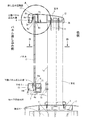
本実施による手摺は、図1のように、躯体6上部のパネル挿し込み側端部に設置するものであり、躯体6上部に所定間隔で複数箇所に起立させる支柱1と、パネル2と、笠木3と、下枠4とから構成してある。支柱1は、中空押出形材で形成されており、下端にはアンカープレート5が取り付けてあるとともに、そのアンカープレート5を躯体6上部に載置し且つネジ11で固定してある。また、支柱1下部のパネル挿し込み側の見付け面1aには、支柱1からパネル挿し込み側に向けて突出した水平片を有する下部ブラケット7がネジ11で固定してあり、その下部ブラケット7の上部には、下枠支持材14がネジ11で固定してある。
As shown in FIG. 1, the handrail according to the present embodiment is installed at the end of the housing 6 on the panel insertion side. The
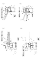
笠木3は、幅広で且つ縦断面ほぼ横長矩形状の中空押出形材で形成してあり、図2(a)のように、下端部3aには下向きに開口した上側パネル呑込み溝8を有している。また、上側パネル呑込み溝8は、笠木3下端部3aのパネル挿し込み側寄りの位置に設けてあり、上側パネル呑込み溝8を構成するパネル挿し込み側溝壁部8aは、溝底(上側パネル呑込み溝上方)側から笠木3の下端部3a(溝開口部側)に向かって次第に広がる方向に傾斜しており、また、他側溝壁部8cは、ほぼ垂直に形成してあることでほぞ溝状をなしている。さらに、パネル挿し込み側溝壁部8aの上側には、上側パネル呑込み溝8と連続する挿し込み空間部17が設けてあり、この挿し込み空間部17を構成するパネル挿し込み側隔壁部8bは、パネル挿し込み側溝壁部8aの上端部から連続しており、挿し込み空間部17における他側溝壁部8cまでの幅はほぼ均一となっている。また、パネル挿し込み側隔壁部8b内周側におけるパネル挿し込み側溝壁部8a寄りの箇所と、他側溝壁部8cの溝開口部内周側には、それぞれに気密材9a,9bが配置してあり、この気密材9a,9bは、笠木3に設けてある保持溝部10a,10bに嵌合してある。また、笠木3と支柱1の取付構造については、図1を参照すれば、支柱1の上端部にほぼ水平な板状をなす上部ブラケット12が取り付けてあり、笠木3下端部の他側に設けてある凹部3bに嵌合するとともに、ネジ11により笠木3と上部ブラケット12を連通して支柱1上端部にネジ止めしてある。
The
下枠4は、図1と図3(c)(d)のように、下側パネル呑込み溝13を有し、その他側部には、下方に伸びるほぼ垂直な下枠取付片4aが設けてある。また、支柱1のパネル挿し込み側の見付け面1aには、下部ブラケット7がネジ11で固定してあり、下部ブラケット7の上部には、パネル挿し込み側の他側部に垂直壁部14aを有するブロック状をなす下枠支持材14が固定してある。また、下枠支持材14の垂直壁部14aの下端部からパネル挿し込み側に向かって伸びる水平壁部14bが設けてあり、この水平壁部14bには、前述した下枠支持材14のブロック部分とほぼ同一形状をなす押縁材15が嵌合され、下枠4を隠蔽して手摺の外観意匠性を向上させている。そして、パネル2下端部を下側パネル呑込み溝13で保持した下枠4の下枠取付片4aを下枠支持材14の垂直壁部14aに当接してネジ11で固定し、さらに、下枠4を挟むかたちで下枠支持材14の水平壁部14bに押縁材15を嵌合している。
The lower frame 4 has a lower
次に、本手摺の施工手順のうち、パネルの取付手順について以下に説明する。
第1の手順として、図3(a)のように、パネル2を支柱1パネル挿し込み側から斜め上方に向けて持ち上げ、パネル2の上端部を笠木3の上側パネル呑込み溝8の溝パネル挿し込み側溝壁部8aの傾斜に沿って挿し入れる。
第2の手順として、図3(b)のように、挿し入れたパネル2の上端部先端が笠木3の上側パネル呑込み溝8から挿し込み空間部17まで到達したら、他側溝壁部8cの内周側に設けてある気密材9bにパネル2の他側面が当たる位置まで、パネル2の上端部を軸としてパネル2を他側に向けて回動する。
第3の手順として図3(c)のように、パネル2の回動に伴って、パネル2下端部に取り付けてある下枠4の下枠取付片4aが下枠支持材14の垂直壁部14aに当接するので、その位置で下枠取付片4aと下枠支持材14にネジ11を挿通して互いをネジ止めする。
第4の手順として、図3(d)のように、下枠支持材14の水平壁部14bに押縁材15を嵌合し、押縁材15と下枠支持材14により下枠4を両側から保持する。以上の手順を減ることにより本実施による手摺におけるパネル2の取付作業が完了する。
Next, the panel attachment procedure among the construction procedures of the handrail will be described below.
As a first procedure, as shown in FIG. 3A, the
As the second procedure, as shown in FIG. 3B, when the tip of the upper end of the inserted
As a third procedure, as shown in FIG. 3C, the lower
As a fourth procedure, as shown in FIG. 3 (d), the
上記の手順を経ることにより、笠木3の上側パネル呑込み溝8と下枠4の下側パネル呑込み溝13に、パネル2の上端部と下端部がそれぞれ保持された手摺が形成される。また、笠木3の上側パネル呑込み溝8の溝開口部がパネル挿し込み側に広く開いており、パネル2の上端部を挿し込むときにパネル2を受け止める的が広くなることで、作業者はパネル2を挿し込みやすくなる。さらに、上側パネル呑込み溝8にパネル2上端部を挿し込んだ後、上側パネル呑込み溝8のパネル挿し込み側溝壁部8a内周側の傾斜を利用してパネル2をさらに押し込み、パネル2の上端部先端を挿し込み空間部17に入れることで、パネル2の回動が妨げられないようにし、ここから、パネル2の上端部を軸としてパネル2を回動してパネル2を垂直な状態に立て、パネル2の下端部に取り付けてある下枠4の下枠取付片4aを下枠支持材14に当接して互いをネジ11止めすることにより、パネル2の他側面とパネル挿し込み側面の両面にそれぞれ気密材9a,9bが当接する。この結果、気密材9a,9bを後付けすることなく、笠木3の上側パネル呑込み溝8と下枠4の下側パネル呑込み溝13にパネル2の上下端部が保持された手摺を形成する。
By passing through the above procedure, the handrails in which the upper end portion and the lower end portion of the
図4(a)(b)に示すものは、本発明の手摺の他の実施形態である。
本実施のものでは、図4(a)のように、パネル2が笠木32と支柱31間、および図示は省略するが下枠で囲まれた位置に保持する手摺である。このような態様の手摺であっても、上側パネル呑込み溝8を上記実施形態(図1に示す手摺)と同様、溝開口部がパネル挿し込み側に広く形成してあり、パネル挿し込み側溝壁部8aが傾斜していることで、パネル2を挿し入れる際、パネル2を容易に取り付けることができる。さらに、図4(b)のように、パネル2が笠木42と両側枠43、及び、図示は省略するが、支柱41のパネル挿し込み側の見付け面から持ち出して取り付けてある下枠の内周側のそれぞれで保持するものでもよい。この場合でも、上記実施形態と同様に、パネル2上端部を笠木42の上側パネル呑込み溝8に斜め下側から角度を付けて挿し入れることにより、パネル2を容易に取り付けることができる。
4 (a) and 4 (b) show another embodiment of the handrail of the present invention.
In the present embodiment, as shown in FIG. 4A, the
本発明では、笠木3,32,42の形状や大きさについて上記の各実施形態に限定されない。また、パネル2についても、上記各実施形態ではガラス製パネルを使用しているが、その他、樹脂性パネルや木製パネル等であってもよい。また、本発明による手摺は、上記実施形態ではバルコニーに適用したものについて説明しているが、通路やスロープ、階段、間仕切り等、その適用範囲を限定するものではない。
In the present invention, the shape and size of the
1,31,41 支柱
2 パネル
3,32,42 笠木
4 下枠
4a 下枠取付片
6 躯体
8 上側パネル呑込み溝
8a パネル挿し込み側溝壁部
8b パネル挿し込み側隔壁部
8c 他側溝壁部
9a,9b 気密材
11 ネジ
13 下側パネル呑込み溝
14 下枠支持材
17 挿し込み空間部
1,31,41
Claims (2)
支柱は、躯体上に所定間隔をあけて複数立設し、笠木は、各支柱の上部間に架設するとともに、下向きに開口した上側パネル呑込み溝を有し、下枠は、各支柱の下部間に配置するとともに、上向きに開口した下側パネル呑込み溝を有しており、パネルは、上端部を上側パネル呑込み溝に下方から挿し込んで保持してあるとともに、その下端部を下側パネル呑込み溝に保持してあり、上側パネル呑込み溝は、溝底側の溝幅に比べて溝開口部の溝幅が広く開口するとともに、少なくともパネル挿し込み側溝壁部が溝開口部に向かうに従って広がる方向に傾斜しており、上側パネル呑込み溝の溝底側より上側には、上側パネル呑込み溝と連続する挿し込み空間部が設けてあり、
気密材は、挿し込み空間部におけるパネル挿し込み側隔壁部の内周側と、他側溝壁部の内周側におけるパネル挿し込み側隔壁部の気密材よりも下位置に設けてあることを特徴とする手摺。 It has struts, panels, caps, a lower frame, and airtight materials,
A plurality of struts are erected on the chassis at predetermined intervals, the headboard is installed between the upper portions of the respective struts, and has an upper panel insertion groove opened downward, and the lower frame is a lower portion of each strut The upper panel insertion groove is inserted into the upper panel insertion groove from below, and the lower end of the lower panel insertion groove is held downward. It is held in the side panel insertion groove, and the upper panel insertion groove has a groove opening width wider than the groove width on the groove bottom side, and at least the panel insertion side groove wall portion is the groove opening portion. It is inclined in a direction that widens toward the upper side, and an insertion space portion that is continuous with the upper panel insertion groove is provided above the groove bottom side of the upper panel insertion groove,
The airtight material is provided at a position lower than the airtight material of the panel insertion side partition wall portion on the inner peripheral side of the panel insertion side partition wall portion in the insertion space portion and the inner peripheral side of the other side groove wall portion. A handrail.
Priority Applications (1)
| Application Number | Priority Date | Filing Date | Title |
|---|---|---|---|
| JP2010284879A JP5685710B2 (en) | 2010-12-21 | 2010-12-21 | handrail |
Applications Claiming Priority (1)
| Application Number | Priority Date | Filing Date | Title |
|---|---|---|---|
| JP2010284879A JP5685710B2 (en) | 2010-12-21 | 2010-12-21 | handrail |
Publications (2)
| Publication Number | Publication Date |
|---|---|
| JP2012132198A true JP2012132198A (en) | 2012-07-12 |
| JP5685710B2 JP5685710B2 (en) | 2015-03-18 |
Family
ID=46648095
Family Applications (1)
| Application Number | Title | Priority Date | Filing Date |
|---|---|---|---|
| JP2010284879A Active JP5685710B2 (en) | 2010-12-21 | 2010-12-21 | handrail |
Country Status (1)
| Country | Link |
|---|---|
| JP (1) | JP5685710B2 (en) |
Cited By (5)
| Publication number | Priority date | Publication date | Assignee | Title |
|---|---|---|---|---|
| JP2016098599A (en) * | 2014-11-25 | 2016-05-30 | ビニフレーム工業株式会社 | Hand rail |
| JP2017089173A (en) * | 2015-11-06 | 2017-05-25 | 三協立山株式会社 | handrail |
| JP2017166125A (en) * | 2016-03-14 | 2017-09-21 | 三協立山株式会社 | handrail |
| JP2017166127A (en) * | 2016-03-14 | 2017-09-21 | 三協立山株式会社 | handrail |
| JP7216443B1 (en) | 2021-09-10 | 2023-02-01 | ビニフレーム工業株式会社 | handrail |
Citations (6)
| Publication number | Priority date | Publication date | Assignee | Title |
|---|---|---|---|---|
| JPH0210492A (en) * | 1988-06-28 | 1990-01-16 | Matsushita Refrig Co Ltd | Display device |
| JPH0835211A (en) * | 1994-07-22 | 1996-02-06 | Shibiru Kankyo Eng Kk | Translucent soundproof wall |
| JP2004027515A (en) * | 2002-06-21 | 2004-01-29 | Sanki Eng Co Ltd | Partition metal fitting and partition |
| JP2006161486A (en) * | 2004-12-09 | 2006-06-22 | Nittetsu Steel Sheet Corp | Connection structure of panel |
| JP2007035741A (en) * | 2005-07-25 | 2007-02-08 | Sumitomo Wiring Syst Ltd | Circuit board storing structure |
| JP2010209598A (en) * | 2009-03-11 | 2010-09-24 | San Rail:Kk | Device and method for mounting handrail |
-
2010
- 2010-12-21 JP JP2010284879A patent/JP5685710B2/en active Active
Patent Citations (6)
| Publication number | Priority date | Publication date | Assignee | Title |
|---|---|---|---|---|
| JPH0210492A (en) * | 1988-06-28 | 1990-01-16 | Matsushita Refrig Co Ltd | Display device |
| JPH0835211A (en) * | 1994-07-22 | 1996-02-06 | Shibiru Kankyo Eng Kk | Translucent soundproof wall |
| JP2004027515A (en) * | 2002-06-21 | 2004-01-29 | Sanki Eng Co Ltd | Partition metal fitting and partition |
| JP2006161486A (en) * | 2004-12-09 | 2006-06-22 | Nittetsu Steel Sheet Corp | Connection structure of panel |
| JP2007035741A (en) * | 2005-07-25 | 2007-02-08 | Sumitomo Wiring Syst Ltd | Circuit board storing structure |
| JP2010209598A (en) * | 2009-03-11 | 2010-09-24 | San Rail:Kk | Device and method for mounting handrail |
Cited By (6)
| Publication number | Priority date | Publication date | Assignee | Title |
|---|---|---|---|---|
| JP2016098599A (en) * | 2014-11-25 | 2016-05-30 | ビニフレーム工業株式会社 | Hand rail |
| JP2017089173A (en) * | 2015-11-06 | 2017-05-25 | 三協立山株式会社 | handrail |
| JP2017166125A (en) * | 2016-03-14 | 2017-09-21 | 三協立山株式会社 | handrail |
| JP2017166127A (en) * | 2016-03-14 | 2017-09-21 | 三協立山株式会社 | handrail |
| JP7216443B1 (en) | 2021-09-10 | 2023-02-01 | ビニフレーム工業株式会社 | handrail |
| JP2023040865A (en) * | 2021-09-10 | 2023-03-23 | ビニフレーム工業株式会社 | handrail |
Also Published As
| Publication number | Publication date |
|---|---|
| JP5685710B2 (en) | 2015-03-18 |
Similar Documents
| Publication | Publication Date | Title |
|---|---|---|
| EP2105573B1 (en) | A sliding door arrangement | |
| JP5685710B2 (en) | handrail | |
| KR100769517B1 (en) | Handrail of building | |
| KR20200053252A (en) | Banister support fixing structure of deck rod | |
| JP5603920B2 (en) | Extended structure support structure | |
| CN112593652B (en) | Slide rail type stone assembling and mounting structure and construction method thereof | |
| JP4904070B2 (en) | Soil concrete uneven absorption device for outdoor structures | |
| JP5705504B2 (en) | handrail | |
| JP5627505B2 (en) | Simple building | |
| JP5350704B2 (en) | Building frame | |
| JP5517210B2 (en) | handrail | |
| JP2009185562A (en) | Eaves structure of building | |
| JP5308168B2 (en) | Unit building | |
| KR100889023B1 (en) | Three-Dimensional curtain wall | |
| JP6055257B2 (en) | Structure of the overhang space | |
| JP5714474B2 (en) | Joinery and construction method of joinery | |
| JP6486108B2 (en) | Gatepost | |
| JP5953017B2 (en) | Exterior construction method | |
| JP2008280762A (en) | Handrail for veranda | |
| JP2010048013A (en) | Bearing wall and mounting structure of the same | |
| JP7074980B2 (en) | How to install the partition for the balcony | |
| JP6845609B2 (en) | handrail | |
| JP5687919B2 (en) | Assembly building and construction method of assembly building | |
| JP2007138499A (en) | Projecting handrail | |
| JP6775392B2 (en) | Fence or rail |
Legal Events
| Date | Code | Title | Description |
|---|---|---|---|
| A621 | Written request for application examination |
Free format text: JAPANESE INTERMEDIATE CODE: A621 Effective date: 20131107 |
|
| A977 | Report on retrieval |
Free format text: JAPANESE INTERMEDIATE CODE: A971007 Effective date: 20140820 |
|
| A131 | Notification of reasons for refusal |
Free format text: JAPANESE INTERMEDIATE CODE: A131 Effective date: 20141104 |
|
| A521 | Request for written amendment filed |
Free format text: JAPANESE INTERMEDIATE CODE: A523 Effective date: 20141126 |
|
| TRDD | Decision of grant or rejection written | ||
| A01 | Written decision to grant a patent or to grant a registration (utility model) |
Free format text: JAPANESE INTERMEDIATE CODE: A01 Effective date: 20141216 |
|
| A61 | First payment of annual fees (during grant procedure) |
Free format text: JAPANESE INTERMEDIATE CODE: A61 Effective date: 20141217 |
|
| R150 | Certificate of patent or registration of utility model |
Ref document number: 5685710 Country of ref document: JP Free format text: JAPANESE INTERMEDIATE CODE: R150 |
|
| R250 | Receipt of annual fees |
Free format text: JAPANESE INTERMEDIATE CODE: R250 |
|
| R250 | Receipt of annual fees |
Free format text: JAPANESE INTERMEDIATE CODE: R250 |