JP2009185562A - Eaves structure of building - Google Patents
Eaves structure of building Download PDFInfo
- Publication number
- JP2009185562A JP2009185562A JP2008028595A JP2008028595A JP2009185562A JP 2009185562 A JP2009185562 A JP 2009185562A JP 2008028595 A JP2008028595 A JP 2008028595A JP 2008028595 A JP2008028595 A JP 2008028595A JP 2009185562 A JP2009185562 A JP 2009185562A
- Authority
- JP
- Japan
- Prior art keywords
- case
- eaves
- wall
- building
- shutter case
- Prior art date
- Legal status (The legal status is an assumption and is not a legal conclusion. Google has not performed a legal analysis and makes no representation as to the accuracy of the status listed.)
- Granted
Links
Images


Abstract
Description
傾斜屋根を有する建物の軒先構造に関する。 The present invention relates to an eaves structure of a building having an inclined roof.
傾斜屋根が外壁から突出して形成されている建物においては、外壁に設けられたシャッターを収納するシャッターケースが外壁の上方かつ軒下に配置されることがある。狭小敷地に建てられる建物では、軒先出寸法が短くなっているので、この軒先出寸法が短い場合に対応させる軒先構造の従来例がある(例えば、特許文献1参照)。 In a building in which an inclined roof projects from the outer wall, a shutter case that houses a shutter provided on the outer wall may be disposed above the outer wall and below the eaves. In a building built on a narrow site, since the eaves protrusion dimension is shortened, there is a conventional example of an eave structure that corresponds to the case where the eave protrusion dimension is short (for example, see Patent Document 1).
特許文献1では、外壁と屋根パネルとを備えた建物において、外壁の上方にシャッターケースが配設され、屋根パネルの先端に取り付けられた見切材から外壁にわたって軒天材が配設されている点が示されている。シャッターケースを隠すため、軒天材は屋根パネルに取り付けられた鼻隠し材や吊り材により支持され、シャッターケースの下方に配設されている点が示されている。
しかし、特許文献1では、敷地に合わせて屋根パネルの長さ寸法が短くなるので、屋根パネルの長さ寸法によって軒天材の高さ寸法を調整しなければならない。そのため、軒天材の高さに対応した様々な長さ寸法の鼻隠し材や吊り材が必要となる。このため、部品点数が増加し、コストが高くなり、施工性が低下する。 However, in patent document 1, since the length dimension of a roof panel becomes short according to a site, you have to adjust the height dimension of an eaves ceiling material with the length dimension of a roof panel. For this reason, nasal cover materials and suspension materials having various lengths corresponding to the height of the eaves are required. For this reason, a number of parts increases, cost becomes high, and workability falls.
本発明は、コストの増加を抑えて施工性が向上した建物の軒先構造を提供することを目的とする。 An object of this invention is to provide the eaves structure of the building which suppressed the increase in cost and the workability improved.
本発明の建物の軒先構造は、図面を参照すると、窓23が設けられた外壁材22と、この外壁材の窓の上側に配置されたシャッターケース41と、このシャッターケースを軒先部分で覆うとともに傾斜屋根を形成する屋根部材31とを備えた建物の軒先構造であって、前記シャッターケースは、前記外壁材の表面と略同様の模様が形成された模様部を有することを特徴とする。
Referring to the drawings, the eaves structure of the building of the present invention includes an
この発明によれば、シャッターケースを外壁材の表面と略同様の模様に形成させたので、デザイン上の統一がとれシャッターケースを外部から見ても目立たず、意匠性を向上させることができる。また、軒天材にてシャッターケースを隠す必要がないので、軒天材を支持する鼻隠し部材や吊り材を設ける必要がない。そのため、部品コストの増大を抑えられるとともに、組み立ても容易になり、施工性を向上させることができる。また、シャッターケースの露出を防ぐために、シャッターケース自体を小さくする必要もないので、シャッターケースを共通して使用でき、部品コストの増大をさらに抑えることができる。 According to the present invention, since the shutter case is formed in a pattern substantially the same as the surface of the outer wall material, the design can be unified and the shutter case is not conspicuous even when viewed from the outside, and the design can be improved. Further, since it is not necessary to hide the shutter case with the eaves top material, there is no need to provide a nose cover member or a suspension material that supports the eaves top material. Therefore, an increase in component costs can be suppressed, assembly can be facilitated, and workability can be improved. Further, since it is not necessary to make the shutter case itself small in order to prevent the exposure of the shutter case, the shutter case can be used in common, and the increase in the parts cost can be further suppressed.
ここで、建物の軒先構造にかかる本発明では、前記模様部は、前記シャッターケースの正面および側面に設けられている構成が好ましい。
この構成の発明では、シャッターケースの模様部を斜め方向から見た際にも外観を良好にすることができる。
Here, in this invention concerning the eaves-end structure of a building, the structure in which the said pattern part is provided in the front and side surface of the said shutter case is preferable.
In the invention of this configuration, the appearance can be improved even when the pattern portion of the shutter case is viewed from an oblique direction.
前記外壁材および前記模様部の模様は、それぞれ水平方向に連続して延びる複数の横溝22A、41Aが形成されている構成が好ましい。
この構成の発明では、シャッターケースを斜めから見た場合、横溝を外壁材と模様部とに連続して複数形成させているので、デザインの統一性を向上させることができる。また、外壁材および模様部の模様は溝から形成されているので、模様を形成するために新たな部材を設けずに済むから、部品コストの増大を抑えることができる。
The outer wall material and the pattern of the pattern portion preferably have a plurality of
In the invention of this configuration, when the shutter case is viewed obliquely, a plurality of lateral grooves are continuously formed in the outer wall material and the pattern portion, so that design uniformity can be improved. Further, since the outer wall material and the pattern of the pattern portion are formed from the grooves, it is not necessary to provide a new member for forming the pattern, so that it is possible to suppress an increase in component costs.
前記外壁材および前記模様部の模様は、鉛直方向に連続する縦溝22B、41Bが形成されている構成が好ましい。
この構成の発明では、横溝だけでなく、縦溝も形成させているので、デザインの統一性をさらに向上させることができる。
The outer wall material and the pattern of the pattern portion preferably have a configuration in which
In the invention of this configuration, not only the horizontal grooves but also the vertical grooves are formed, so that the design uniformity can be further improved.
前記屋根部材の軒先から前記シャッターケースに亘って取り付けられた軒天材36を備え、前記模様部の横溝は、前記軒天材の端部に係合して固定する構成が好ましい。
この構成の発明では、軒天材を設けることにより、屋根パネルの内部に虫などが侵入することを防止できる。また、模様部に形成された横溝は、外観性を向上させる際にも軒天材を固定する際にも共用することができる。つまり、シャッターケースおよび外壁パネルに共通の模様を有する新たな部材を設ける必要がなく、しかも、軒天材を固定するための新たな部材も設ける必要もないので、部品点数が増加しないから、意匠性および施工性が向上し、大幅にコストダウンが図れる。
It is preferable that the eaves
In the invention of this configuration, it is possible to prevent insects and the like from entering the inside of the roof panel by providing the eaves top material. Further, the lateral groove formed in the pattern portion can be shared both when improving the appearance and when fixing the eaves top material. In other words, there is no need to provide a new member having a common pattern on the shutter case and the outer wall panel, and there is no need to provide a new member for fixing the eave roof material, so the number of parts does not increase. The workability and workability are improved and the cost can be greatly reduced.
[第1実施形態]
以下に本発明の第1実施形態を図1〜3に基づいて説明する。
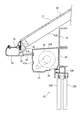
図1は、第1実施形態にかかるユニット式建物の全体の概略構成を示す斜視図である。図2は、建物ユニットの軒先構造を示す断面図である。図3は、軒先構造のシャッター近傍を示す斜視図である。なお、説明の都合上、図3では、屋根パネルや軒天材などは省略する。
[First embodiment]
A first embodiment of the present invention will be described below with reference to FIGS.
FIG. 1 is a perspective view showing an overall schematic configuration of a unit building according to the first embodiment. FIG. 2 is a cross-sectional view showing an eaves-end structure of a building unit. FIG. 3 is a perspective view showing the vicinity of the shutter of the eaves-end structure. For convenience of explanation, in FIG. 3, roof panels and eaves materials are omitted.
図1に示すように、狭小敷地に建てられたユニット式建物1は、基礎10上に積層配列された箱形の建物ユニット21からなる建物本体20と、この建物本体20の上に設けられた傾斜屋根部30とを含んで構成されている。
建物ユニット21は、四本の柱、天井梁および床梁で直方体状に形成された骨組みを有する。この骨組みの屋外に面した表面には、軽量気泡コンクリートで形成された外壁材としての外壁パネル22が取り付けられている。また、いくつかの建物ユニット21の表面には、外壁パネル22とともに、サッシ等からなる窓23が取り付けられている。この窓23の上側にはシャッター40が設置されている。
また、上階の建物ユニット21には、二つの建物ユニット21に亘って、手すり壁部27を有するベランダ26が設けられている。
As shown in FIG. 1, a unit building 1 built on a small site is provided with a
The
The
図2に示すように、傾斜屋根部30は、屋根パネル31にて形成され、この屋根パネル31は、図示しない束を介して建物本体20に支持されている。屋根パネル31は、下地フレーム31Aを有し、下地フレーム31Aの軒先に継ぎ材32およびブラケット33を介して樋34が取り付けられ、継ぎ材32の下端部に見切材35が取り付けられている。
シャッター40は、2枚の窓ガラス23Bがはめられたサッシ23Aの上端部と、ブラケット25が取り付けられた上梁24とにて固定されている。そして、シャッター40は、軒先で屋根パネル31にて覆われている。シャッター40は、箱型のシャッターケース41と、このシャッターケース41に収納され、窓23を塞ぐためのシャッター本体42を備える。シャッター本体42は、シャッターケース41から鉛直方向で下方に向かって取り付けられた図示しないレールと、このレールに案内される複数の板状のスラット42Aとを有する。
As shown in FIG. 2, the
The
また、図1〜図3に示すように、シャッターケース41の正面および側面には、水平方向に延びるケース横溝41Aが複数形成されている。
ケース横溝41Aには、図2に示すように、平板状の軒天材36の一端部が係合固定され、軒天材36の他端部は、見切材35にて固定されている。シャッターケース41の軒天材36よりも下側は、外部から視認可能である。
また、図1に示すように、軒先のシャッターケース41だけでなく、建物本体20の1階に設けられたシャッターケース41にも外壁横溝22Aと同様の模様が形成されている。
1 to 3, a plurality of case
As shown in FIG. 2, one end portion of a flat
As shown in FIG. 1, not only the
外壁パネル22は、図1および図3に示すように、水平方向に延びる複数の外壁横溝22Aが形成されている。この外壁横溝22Aは、シャッターケース41に設けられたケース横溝41Aに連続して形成されている。これらケース横溝41Aおよび外壁横溝22Aは、鉛直方向にそれぞれ所定の間隙を有しているが、それぞれの間隙の長さ寸法は一定でもよく、異なっていても良い。
さらに、2階バルコニーの手すり壁部27の正面および側面にも、同様に、水平方向に延びる手すり壁溝27Aが複数形成されている。
As shown in FIGS. 1 and 3, the
Further, a plurality of
[第1実施形態の効果]
このような第1実施形態によれば、次のような作用効果を奏することができる。
(1)シャッターケース41に、外壁パネル22の外壁横溝22Aと略同様のケース横溝41Aを形成させた。
そのため、デザインの統一性がとれ、シャッターケース41を外部から見ても目立たず、意匠性を向上させることができる。
[Effect of the first embodiment]
According to such 1st Embodiment, there can exist the following effects.
(1) In the
Therefore, design uniformity can be achieved, and the design can be improved without being noticeable even when the
(2)また、軒天材36にてシャッターケース41を隠す必要がないので、軒天材36を支持する鼻隠し部材や吊り材を設ける必要がない。
そのため、部品コストの増大を抑えられるとともに、組み立ても容易になり、施工性を向上させることができる。
(2) Further, since it is not necessary to hide the
Therefore, an increase in component costs can be suppressed, assembly can be facilitated, and workability can be improved.
(3)また、シャッターケース41の露出を防ぐために、シャッターケース41自体を小さくする必要がない。
そのため、様々な建物1にもシャッターケース41を共通して使用でき、部品コストの増大をさらに抑えることができる。
(3) In order to prevent the exposure of the
For this reason, the
(4)そして、軒先のシャッターケース41だけでなく、1階のシャッターケース41にも同様に、ケース横溝41Aを形成させた。
そのため、建物本体20全体として、デザインの統一性が向上する。
(4) Then, not only the
For this reason, design uniformity is improved as a whole of the
(5)バルコニーの手すり壁部27の正面および側面にも、水平方向に延びる手すり壁溝27Aを形成させた。
そのため、建物本体20の外壁に全体的に溝が形成されているので、デザインの統一性がさらに向上する。
(5) A
Therefore, since the groove is formed entirely on the outer wall of the
(6)建物1を狭小敷地に建てた。
そのため、屋根パネル31の長さ寸法が短くなり、シャッターケース41の外部から視認できる部分が大きくなるが、この場合でもシャッターケース41に、外壁横溝22Aと略同等のケース横溝41Aを形成したので、シャッターケース41が目立たず、意匠性を向上させることができる。
(6) Building 1 was built on a small site.
Therefore, the length dimension of the
(7)シャッターケース41の正面と側面とに外壁パネル22と略同様の模様を設けた。
そのため、シャッターケース41を斜め方向から見た際にも外観を良好にすることができる。
(7) A pattern substantially similar to that of the
Therefore, the appearance can be improved even when the
(8)外壁パネル22およびシャッターケース41に、それぞれ水平方向に延びる複数の外壁横溝22Aおよびケース横溝41Aを連続して形成した。
そのため、シャッターケース41を斜めから見た場合、デザインの統一性を向上させることができる。
(8) In the
Therefore, design uniformity can be improved when the
(9)また、外壁パネル22に外壁縦溝22Bを形成し、シャッターケース41にケース縦溝41Bを形成した。
そのため、外壁横溝22Aやケース横溝41Aだけでなく、外壁縦溝22Bやケース縦溝22Bも形成させているので、デザインの統一性をさらに向上させることができる。
(9) Further, the outer wall
Therefore, not only the outer wall
(10)見切材35とシャッターケース41とで固定させて、軒先に軒天材36を配置した。
そのため、屋根パネル31の内部に虫などが侵入することを防止できる。
(10) The
Therefore, insects and the like can be prevented from entering the
(11)軒天材36の端部にケース横溝41Aを係合させて軒天材36を固定した。
そのため、ケース横溝41Aは、外観性を向上させる際にも軒天材36を固定する際にも共用することができる。
(11) The
Therefore, the case
[第2実施形態]
次に、本発明の第2実施形態を図4に基づいて説明する。
図4は、本発明の第2実施形態の軒先構造の断面図である。
第2実施形態の軒先構造では、軒天材を配設する構成が異なる以外は第1実施形態と同様の構成であるので、軒天材を配設する構成のみを説明する。
図4に示すように、シャッター40の上端部およびブラケット25には、固定具37が取り付けられている。見切材35から固定具37にわたって、屋根パネル31に沿って軒天材36Aが配設されている。また、軒天材36Aの略中央には、シャッターケース41の上端縁が当接しており、軒天材36Aがシャッターケース41にて支持されている。見切材35、固定具37およびシャッターケース41により軒天材36Aを固定している。
また、第2実施形態では、第1実施形態の場合よりも軒天材36Aが上方に傾斜しているので、シャッターケース41の外部から視認可能な部分が大きい状態である。
[Second Embodiment]
Next, a second embodiment of the present invention will be described with reference to FIG.
FIG. 4 is a cross-sectional view of the eaves tip structure of the second embodiment of the present invention.
The eaves tip structure of the second embodiment has the same configuration as that of the first embodiment except that the configuration of arranging the eave roof material is different. Therefore, only the configuration of arranging the eave roof material will be described.
As shown in FIG. 4, a
Further, in the second embodiment, since the
[第2実施形態の効果]
このような第2実施形態によれば、上述した第1実施形態の作用効果(1)〜(10)および以下の作用効果を奏することができる。
(12)軒天材36Aを上方に傾斜させたので、シャッターケース41の外部から視認可能な部分が第1実施形態の場合よりも大きくなるが、シャッターケース41に外壁パネル22の外壁横溝22Aと略同様のケース横溝41Aを形成させたので、シャッターケース41が目立たず、意匠性を向上させることができる。
[Effect of the second embodiment]
According to such 2nd Embodiment, there can exist the effect (1)-(10) of the 1st Embodiment mentioned above, and the following effect.
(12) Since the
(13)また、軒天材36Aを上方に傾斜させているので、外側から軒天材36Aが見えにくく、建物の意匠性をさらに向上させることができる。
(13) Since the
[第3実施形態]
次に、本発明の第3実施形態を図5に基づいて説明する。
図5は、第3実施形態にかかる軒先構造のシャッターケース近傍の斜視図である。第3実施形態の軒先構造では、シャッターケースおよび外壁パネルに溝を形成する構成が異なる以外は第一実施形態と同様の構成であるので、溝を形成する構成のみを説明する。なお、説明の都合上、図5では、屋根パネルや軒天材などは省略する。
[Third embodiment]
Next, a third embodiment of the present invention will be described with reference to FIG.
FIG. 5 is a perspective view of the vicinity of the shutter case of the eaves structure according to the third embodiment. Since the eaves-end structure of the third embodiment is the same as that of the first embodiment except that the configuration for forming the grooves in the shutter case and the outer wall panel is different, only the configuration for forming the grooves will be described. For convenience of explanation, in FIG. 5, roof panels, eaves materials, and the like are omitted.
図5に示すように、シャッターケース41および外壁パネル22には、それぞれ水平方向に連続して延びるケース横溝41Aおよび外壁横溝22Aが形成されている。また、シャッターケースには、鉛直方向に延びるケース縦溝41Bが形成され、外壁パネル22にも同様に鉛直方向に延びる外壁縦溝22Bが形成されている。
As shown in FIG. 5, the
また、外壁パネル22に形成された外壁横溝22Aおよびシャッターケース41に形成されたケース横溝41Aは、第1実施形態と同様に軒天材36の端部に係合させて固定することができる。
Further, the outer wall
[第3実施形態の効果]
このような第3実施形態によれば、第1実施形態と同様の作用効果および以下の作用効果を奏することができる。
(14)シャッターケース41には、ケース横溝41Aに加えて、ケース縦溝41Bを形成させるとともに、外壁パネル22にも同様に、外壁横溝22Aに加えて、外壁縦溝22Bを形成させた。
そのため、シャッターケース41は、外壁パネル22と略同様の模様に形成され、さらにデザインの統一性を向上させることができる。
[Effect of the third embodiment]
According to such 3rd Embodiment, there can exist an effect similar to 1st Embodiment, and the following effects.
(14) The
Therefore, the
[変形例]
なお、本発明は、上述した実施の形態に限定されるものではなく、本発明の目的を達成できる範囲で以下に示される変形をも含むものである。
シャッターケース41には、ケース横溝41Aやケース縦溝41Bを形成させ、外壁パネル22には、外壁横溝22Aや外壁縦溝22Bを形成させる構成を示したが、例えば、シャッターケース41と外壁パネル22の表面とが同じ模様であるために、同じ模様が描かれたフィルムやシートをシャッターケース41および外壁パネル22に貼り付けても良い。
[Modification]
In addition, this invention is not limited to embodiment mentioned above, The deformation | transformation shown below is included in the range which can achieve the objective of this invention.
The
また、図1では、建物1に取り付けられた外壁パネル22全てに外壁横溝22Aを形成する構成を示したが、例えば、屋根パネル31が突出する軒先側、すなわち、図1では、建物1の側面のみに外壁横溝22Aを設けても良い。
Moreover, in FIG. 1, although the structure which forms outer wall
さらに、ケース横溝41Aやケース縦溝41Bは、シャッターケース41の正面および側面に形成させる構成を示したが、正面および側面のうち少なくとも一方にケース横溝41Aやケース縦溝41Bを形成させていてもよい。
Furthermore, although the case
そして、第2実施形態では、シャッターケース41および外壁パネル22にそれぞれケース横溝41Aおよび外壁横溝22Aを形成させた構成を示したが、ケース横溝41Aおよび外壁横溝22Aのみを形成させていてもよい。また、ケース縦溝41Bおよび外壁縦溝22Bは、鉛直方向に交差する方向、例えば、45°の方向に傾斜する直線状に形成させていてもよく、ジグザグ状に形成されていてもよい。
また、ケース横溝41A、ケース縦溝41B、外壁横溝22A、外壁縦溝22Bがそれぞれ単数形成される構成でもよい。
In the second embodiment, the case
Moreover, the structure by which the case horizontal groove |
そして、外壁パネル22は、型枠にて成形されていてもよく、この場合、成形する際に外壁横溝22Aを形成してもよい。また、シャッター40を建物1に取り付けた後に外壁横溝22Aを形成してもよい。
And the
また、建物本体20の上側に屋根パネル31を設ける構成を示したが、屋根パネル31の表面にもケース横溝41A、ケース縦溝41B、外壁横溝22A、外壁縦溝22Bと同様の溝を形成させてもよい。この場合では、建物1全体として、デザインの統一性を向上させることができる。
Moreover, although the structure which provides the
本発明は、ユニット式建物に利用できる他、パネル式、軸組み式による建物にも利用できる。 The present invention can be used not only for a unit type building but also for a panel type or a shaft type building.
1……建物
22…外壁材としての外壁パネル
22A…外壁横溝
22B…外壁縦溝
23…窓
31…屋根部材としての屋根パネル
36…軒天材
41…シャッターケース
41A…ケース横溝
41B…ケース縦溝
DESCRIPTION OF SYMBOLS 1 ...
Claims (5)
前記シャッターケースは、前記外壁材の表面と略同様の模様が形成された模様部を有する
ことを特徴とする建物の軒先構造。 An eaves structure of a building comprising an outer wall member provided with a window, a shutter case disposed above the window of the outer wall member, and a roof member that covers the shutter case with an eave portion and forms an inclined roof. And
The eaves structure of a building, wherein the shutter case has a pattern portion on which a pattern substantially the same as the surface of the outer wall material is formed.
前記模様部は、前記シャッターケースの正面および側面に設けられている
ことを特徴とする建物の軒先構造。 In the eaves structure of the building according to claim 1,
The eaves structure of a building, wherein the pattern portion is provided on a front surface and a side surface of the shutter case.
前記外壁材および前記模様部の模様は、それぞれ水平方向に連続して延びる複数の横溝が形成されている
ことを特徴とする建物の軒先構造。 In the eaves structure of the building according to claim 2,
The eaves structure of a building, wherein the outer wall material and the pattern of the pattern portion are each formed with a plurality of horizontal grooves extending continuously in the horizontal direction.
前記外壁材および前記模様部の模様は、鉛直方向に連続する縦溝が形成されている
ことを特徴とする建物の軒先構造。 In the eaves structure of the building according to claim 3,
The eaves structure of a building, wherein the outer wall material and the pattern of the pattern portion are formed with vertical grooves that are continuous in a vertical direction.
前記屋根部材の軒先から前記シャッターケースに亘って取り付けられた軒天材を備え、
前記模様部の横溝は、前記軒天材の端部に係合して固定する
ことを特徴とする建物の軒先構造。 In the eaves structure of the building according to claim 3 or claim 4,
The eaves top member attached over the shutter case from the eaves of the roof member,
The eaves structure of a building is characterized in that the lateral groove of the pattern portion is engaged with and fixed to an end portion of the eave roof material.
Priority Applications (1)
| Application Number | Priority Date | Filing Date | Title |
|---|---|---|---|
| JP2008028595A JP5123685B2 (en) | 2008-02-08 | 2008-02-08 | Building eaves structure |
Applications Claiming Priority (1)
| Application Number | Priority Date | Filing Date | Title |
|---|---|---|---|
| JP2008028595A JP5123685B2 (en) | 2008-02-08 | 2008-02-08 | Building eaves structure |
Publications (2)
| Publication Number | Publication Date |
|---|---|
| JP2009185562A true JP2009185562A (en) | 2009-08-20 |
| JP5123685B2 JP5123685B2 (en) | 2013-01-23 |
Family
ID=41069068
Family Applications (1)
| Application Number | Title | Priority Date | Filing Date |
|---|---|---|---|
| JP2008028595A Expired - Fee Related JP5123685B2 (en) | 2008-02-08 | 2008-02-08 | Building eaves structure |
Country Status (1)
| Country | Link |
|---|---|
| JP (1) | JP5123685B2 (en) |
Cited By (2)
| Publication number | Priority date | Publication date | Assignee | Title |
|---|---|---|---|---|
| JP2013019139A (en) * | 2011-07-08 | 2013-01-31 | Toyota Home Kk | Eaves structure and building |
| WO2022024584A1 (en) * | 2020-07-31 | 2022-02-03 | 積水ハウス株式会社 | Building structure |
Families Citing this family (1)
| Publication number | Priority date | Publication date | Assignee | Title |
|---|---|---|---|---|
| JP5828598B2 (en) * | 2014-01-27 | 2015-12-09 | 株式会社マーベックス | Window solar shading device |
Citations (3)
| Publication number | Priority date | Publication date | Assignee | Title |
|---|---|---|---|---|
| JPH0445890U (en) * | 1990-08-22 | 1992-04-17 | ||
| JPH05195676A (en) * | 1991-07-20 | 1993-08-03 | Sumitomo Metal Mining Co Ltd | Shutter for window |
| JP2007224689A (en) * | 2006-02-27 | 2007-09-06 | Sanwa Shutter Corp | Shutter case in shutter device for construction |
-
2008
- 2008-02-08 JP JP2008028595A patent/JP5123685B2/en not_active Expired - Fee Related
Patent Citations (3)
| Publication number | Priority date | Publication date | Assignee | Title |
|---|---|---|---|---|
| JPH0445890U (en) * | 1990-08-22 | 1992-04-17 | ||
| JPH05195676A (en) * | 1991-07-20 | 1993-08-03 | Sumitomo Metal Mining Co Ltd | Shutter for window |
| JP2007224689A (en) * | 2006-02-27 | 2007-09-06 | Sanwa Shutter Corp | Shutter case in shutter device for construction |
Cited By (3)
| Publication number | Priority date | Publication date | Assignee | Title |
|---|---|---|---|---|
| JP2013019139A (en) * | 2011-07-08 | 2013-01-31 | Toyota Home Kk | Eaves structure and building |
| WO2022024584A1 (en) * | 2020-07-31 | 2022-02-03 | 積水ハウス株式会社 | Building structure |
| GB2611453A (en) * | 2020-07-31 | 2023-04-05 | Sekisui House Kk | Building structure |
Also Published As
| Publication number | Publication date |
|---|---|
| JP5123685B2 (en) | 2013-01-23 |
Similar Documents
| Publication | Publication Date | Title |
|---|---|---|
| JP6208795B2 (en) | Kasagi ventilation parts | |
| JP5123685B2 (en) | Building eaves structure | |
| JP5603920B2 (en) | Extended structure support structure | |
| JP2007308906A (en) | Exterior wall of building, and curtain wall | |
| KR20120065106A (en) | Combination structure of curtain wall louver using for tube carrier | |
| JP2010013875A (en) | Pent-roof structure of residence | |
| JP5393586B2 (en) | Simple building | |
| KR102240604B1 (en) | Bonding System For Curtain-Wall Frame and Method Thereof | |
| JP2021167564A (en) | building | |
| JP6475999B2 (en) | Building ceiling structure | |
| KR101721223B1 (en) | Gallery Window | |
| JP6770343B2 (en) | roof | |
| JP6353358B2 (en) | Surface grid mounting structure | |
| JP7120699B2 (en) | building | |
| JP5775333B2 (en) | Unit for balcony, unit type building and construction method for unit type building | |
| JP6573752B2 (en) | building | |
| JP2010163747A (en) | Unit building | |
| JP5746095B2 (en) | Eave back fire prevention structure | |
| JP2012077574A (en) | Handrail wall and construction method of handrail wall | |
| JP7215652B2 (en) | Curved outer wall fixed structure | |
| JP2009133154A (en) | Exterior wall material and exterior wall equipped with the same | |
| WO2020188619A1 (en) | Building wall | |
| JP6105647B2 (en) | balcony | |
| JP5951285B2 (en) | Building accessories | |
| JP2022182866A (en) | Wall body structure and building |
Legal Events
| Date | Code | Title | Description |
|---|---|---|---|
| A621 | Written request for application examination |
Free format text: JAPANESE INTERMEDIATE CODE: A621 Effective date: 20110127 |
|
| A977 | Report on retrieval |
Free format text: JAPANESE INTERMEDIATE CODE: A971007 Effective date: 20120620 |
|
| A131 | Notification of reasons for refusal |
Free format text: JAPANESE INTERMEDIATE CODE: A131 Effective date: 20120710 |
|
| A521 | Written amendment |
Free format text: JAPANESE INTERMEDIATE CODE: A523 Effective date: 20120907 |
|
| TRDD | Decision of grant or rejection written | ||
| A01 | Written decision to grant a patent or to grant a registration (utility model) |
Free format text: JAPANESE INTERMEDIATE CODE: A01 Effective date: 20121002 |
|
| A01 | Written decision to grant a patent or to grant a registration (utility model) |
Free format text: JAPANESE INTERMEDIATE CODE: A01 |
|
| A61 | First payment of annual fees (during grant procedure) |
Free format text: JAPANESE INTERMEDIATE CODE: A61 Effective date: 20121026 |
|
| FPAY | Renewal fee payment (event date is renewal date of database) |
Free format text: PAYMENT UNTIL: 20151102 Year of fee payment: 3 |
|
| R150 | Certificate of patent or registration of utility model |
Free format text: JAPANESE INTERMEDIATE CODE: R150 Ref document number: 5123685 Country of ref document: JP Free format text: JAPANESE INTERMEDIATE CODE: R150 |
|
| LAPS | Cancellation because of no payment of annual fees |