JP2012131399A - Sealing structure of weather strip for retractable roof vehicle - Google Patents
Sealing structure of weather strip for retractable roof vehicle Download PDFInfo
- Publication number
- JP2012131399A JP2012131399A JP2010285895A JP2010285895A JP2012131399A JP 2012131399 A JP2012131399 A JP 2012131399A JP 2010285895 A JP2010285895 A JP 2010285895A JP 2010285895 A JP2010285895 A JP 2010285895A JP 2012131399 A JP2012131399 A JP 2012131399A
- Authority
- JP
- Japan
- Prior art keywords
- seal
- vehicle
- window glass
- weather strip
- roof
- Prior art date
- Legal status (The legal status is an assumption and is not a legal conclusion. Google has not performed a legal analysis and makes no representation as to the accuracy of the status listed.)
- Granted
Links
- 238000007789 sealing Methods 0.000 title claims abstract description 9
- 239000005357 flat glass Substances 0.000 claims abstract description 54
- 230000002093 peripheral effect Effects 0.000 claims description 8
- XLYOFNOQVPJJNP-UHFFFAOYSA-N water Substances O XLYOFNOQVPJJNP-UHFFFAOYSA-N 0.000 abstract description 32
- 238000009434 installation Methods 0.000 abstract 1
- 238000001125 extrusion Methods 0.000 description 4
- 239000000428 dust Substances 0.000 description 2
- 239000011521 glass Substances 0.000 description 2
- 239000006121 base glass Substances 0.000 description 1
- 230000007423 decrease Effects 0.000 description 1
- 238000000034 method Methods 0.000 description 1
- 238000000465 moulding Methods 0.000 description 1
Images


Classifications
-
- B—PERFORMING OPERATIONS; TRANSPORTING
- B60—VEHICLES IN GENERAL
- B60J—WINDOWS, WINDSCREENS, NON-FIXED ROOFS, DOORS, OR SIMILAR DEVICES FOR VEHICLES; REMOVABLE EXTERNAL PROTECTIVE COVERINGS SPECIALLY ADAPTED FOR VEHICLES
- B60J10/00—Sealing arrangements
- B60J10/70—Sealing arrangements specially adapted for windows or windscreens
- B60J10/74—Sealing arrangements specially adapted for windows or windscreens for sliding window panes, e.g. sash guides
- B60J10/79—Sealing arrangements specially adapted for windows or windscreens for sliding window panes, e.g. sash guides for flush-glass windows, i.e. for windows flush with the vehicle body or the window frame
-
- B—PERFORMING OPERATIONS; TRANSPORTING
- B60—VEHICLES IN GENERAL
- B60J—WINDOWS, WINDSCREENS, NON-FIXED ROOFS, DOORS, OR SIMILAR DEVICES FOR VEHICLES; REMOVABLE EXTERNAL PROTECTIVE COVERINGS SPECIALLY ADAPTED FOR VEHICLES
- B60J10/00—Sealing arrangements
- B60J10/20—Sealing arrangements characterised by the shape
- B60J10/24—Sealing arrangements characterised by the shape having tubular parts
- B60J10/248—Sealing arrangements characterised by the shape having tubular parts having two or more tubular cavities, e.g. formed by partition walls
-
- B—PERFORMING OPERATIONS; TRANSPORTING
- B60—VEHICLES IN GENERAL
- B60J—WINDOWS, WINDSCREENS, NON-FIXED ROOFS, DOORS, OR SIMILAR DEVICES FOR VEHICLES; REMOVABLE EXTERNAL PROTECTIVE COVERINGS SPECIALLY ADAPTED FOR VEHICLES
- B60J10/00—Sealing arrangements
- B60J10/20—Sealing arrangements characterised by the shape
- B60J10/25—Sealing arrangements characterised by the shape characterised by water drainage means
-
- B—PERFORMING OPERATIONS; TRANSPORTING
- B60—VEHICLES IN GENERAL
- B60J—WINDOWS, WINDSCREENS, NON-FIXED ROOFS, DOORS, OR SIMILAR DEVICES FOR VEHICLES; REMOVABLE EXTERNAL PROTECTIVE COVERINGS SPECIALLY ADAPTED FOR VEHICLES
- B60J10/00—Sealing arrangements
- B60J10/70—Sealing arrangements specially adapted for windows or windscreens
- B60J10/74—Sealing arrangements specially adapted for windows or windscreens for sliding window panes, e.g. sash guides
- B60J10/77—Sealing arrangements specially adapted for windows or windscreens for sliding window panes, e.g. sash guides for sashless windows, i.e. for frameless windows forming a seal directly with the vehicle body
- B60J10/777—Sealing arrangements specially adapted for windows or windscreens for sliding window panes, e.g. sash guides for sashless windows, i.e. for frameless windows forming a seal directly with the vehicle body the sealing arrangement being between the edges of adjacent panes
Abstract
Description
本発明は、格納式ルーフ車用ウェザーストリップのシール構造に関する。より詳細には、開閉自在のルーフを折り畳みストレージ内に格納する格納式ルーフ車の有する開閉式クォーターウィンドガラスの前縁に設けられたウェザーストリップのシール構造に関するものである。 The present invention relates to a weatherstrip sealing structure for a retractable roof vehicle. More specifically, the present invention relates to a weather strip sealing structure provided at the front edge of an openable quarter window glass of a retractable roof vehicle that stores an openable / closable roof in a folding storage.
図4は、開閉自在のルーフを折り畳むことによって開放されるタイプの格納式ルーフ車の外観を示している。ルーフは、幌1からなり折り畳まれた幌1は車体後方側下部のトランク2内に格納されるようになっている。なお、幌1にかえて、ルーフをルーフパネルとその後方に位置するバックウインドパネルから構成し、折り畳まれたルーフパネルがバックウインドパネルに重ねられた状態でトランク2内に格納されるものもある。このようなタイプの車両は、一般的に、リトラクタブルハードトップ、クーペカブリオレ、クーペコンバーチブルと称されている。
FIG. 4 shows the appearance of a retractable roof vehicle of a type that is opened by folding an openable / closable roof. The roof is composed of a hood 1, and the folded hood 1 is stored in a
こうした格納式ルーフ車両において、サイドウィンドガラス3に加えて、その後方に位置するクォーターウィンドガラス4も昇降することによって開閉自在にしたタイプのものがある。クォーターウィンドガラス4の前側には、図5及び図6に示すように、クォーターサッシュ5が取付られていて、そのクォーターサッシュ5に対して上下方向に延びるウェザーストリップ10の取付基部11が取付けられている。そして、クォーターウィンドガラス4が昇降するとそれとともにウェザーストリップ10も昇降し、クォーターウィンドガラス4の閉時にはウェザーストリップ10の上端部が、幌1の側縁に沿って取付けられたルーフウェザーストリップ20に弾接するようになっている。また、ウェザーストリップ10には、サイドウィンドガラス3の後端部3aに弾接する中空シール部12とサイドウィンドガラス3の車内側側面に弾接するシールリップ部13が設けられていて、車内外のシール性が確保されている(例えば、特許文献1参照)。
In such a retractable roof vehicle, there is a type in which, in addition to the
しかしながら、従来例で示した格納式ルーフ車両のシール構造によれば、ウェザーストリップ10の上端部はルーフウェザーストリップ20に弾接するとともにサイドウィンドガラス3にも弾接するためウェザーストリップ10が撓んで、図7に示すように、幌1の側端に流れ落ちた雨水や直接かけられる洗車の高圧水といった水Wが、車外側からサイドウィンドガラス3とウェザーストリップ10との間に回り込んで車内側に侵入して水漏れになる場合があった。
また、特許文献1に記載された発明は、ウェザーストリップ20の上端部よりも下方の位置で且つ車内側に開放された領域に水を排水させる排水穴を設けてゴミや塵等を侵入し難くしたものであるが、排水穴の新たに設けたり排水穴に繋がる車外側排水路を設ける必要があるので構造が複雑である。
However, according to the seal structure of the retractable roof vehicle shown in the conventional example, the
Further, the invention described in Patent Document 1 is provided with a drainage hole for draining water in a region below the upper end of the
そこで、本発明の目的とするところは、開閉式クォーターウィンドガラスに取付けられたウェザーストリップ上端部から雨水等が車内側に侵入することを簡易な構造で防止する格納式ルーフ車用ウェザーストリップのシール構造を提供することにある。 Accordingly, an object of the present invention is to provide a weather strip seal for a retractable roof vehicle that prevents rainwater and the like from entering the vehicle interior from the upper end of the weather strip attached to the openable quarter window glass with a simple structure. To provide a structure.
上記の目的を達成するために、請求項1に係る発明は、格納式ルーフ車のクォーターウィンドガラス(4)の前側に設けられたクォーターサッシュ(5)に取付けられ前記クォーターウィンドガラス(4)とともに昇降自在の取付基部(11)と、該取付基部(11)に一体成形されサイドウィンドガラス(3)の後端部(3a)に弾接する中空シール部(12)と、該中空シール部(12)よりも前方で前記取付基部(11)に一体成形され前記サイドウィンドガラス(4)の車内側側面に弾接するシールリップ部(13)を備え、型成形された上端部(101)がルーフ(1)の側縁に沿って取付けられ車両の前後方向に延びるルーフウェザーストリップ(20)に弾接するウェザーストリップ(10)のシール構造であって、
前記型成形された上端部(101)に、車内側から前記上端部(101)の前側角部(P)を覆い車外側に突出形成され前記サイドウィンドガラス(3)に車内側から弾接するシール壁(30)を形成したことを特徴とする。
To achieve the above object, the invention according to claim 1 is attached to a quarter sash (5) provided on the front side of a quarter window glass (4) of a retractable roof vehicle, together with the quarter window glass (4). A vertically movable mounting base (11), a hollow seal portion (12) integrally formed with the mounting base (11) and elastically contacting the rear end (3a) of the side window glass (3), and the hollow seal portion (12 ) And a sealing lip portion (13) which is integrally formed with the mounting base portion (11) and elastically contacts the inner side surface of the side window glass (4), and the molded upper end portion (101) is a roof ( 1) a seal structure of a weather strip (10) which is attached along a side edge of 1) and elastically contacts a roof weather strip (20) extending in the longitudinal direction of the vehicle,
A seal that covers the front corner (P) of the upper end portion (101) from the vehicle inner side and protrudes to the vehicle outer side and elastically contacts the side window glass (3) from the vehicle inner side on the molded upper end portion (101). A wall (30) is formed.
また、請求項2に係る発明は、前記シール壁(30)の車外側周縁を上方から斜め前方に下降させ前記シールリップ部(13)の上端に連設させたことを特徴とする。
Further, the invention according to
さらに、請求項3に係る発明は、前記シール壁(30)の車外側周縁(31)を上方から斜め前方に下降させ前記シールリップ部(13)の上端から所定距離分、下方位置の内側まで延設させ、前記シールリップ部(13)の上端を前記シール壁(30)から前方に離間させたことを特徴とする。
Furthermore, in the invention according to
なお、括弧内の記号は、図面および後述する発明を実施するための形態に記載された対応要素または対応事項を示す。 Note that symbols in parentheses indicate corresponding elements or corresponding matters described in the drawings and modes for carrying out the invention described later.
本発明の請求項1に記載の格納式ルーフ車用ウェザーストリップのシール構造によれば、クォーターウィンドガラスとともに昇降自在でしかもサイドウィンドガラスの後端部と車内側側面に弾接する中空シール部とシールリップ部を備えるウェザーストリップにおいて、型成形された上端部には、前記上端部の前側角部を覆い車外側に突出形成され前記サイドウィンドガラスに車内側から弾接するシール壁が形成されているので、ルーフの側端に流れ落ちた雨水や直接かけられる洗車の高圧水といった水が、車外側からサイドウィンドガラスとウェザーストリップの上端部との間に回り込んだ場合にその回り込んだ水はシール壁の内側に堰き止められてあるいはシール壁の車外側周縁を伝わりシールリップ部の内側、すなわち、中空シール部とシールリップ部の間に導かれる。
よって、ウェザーストリップ上端部とサイドウィンドガラスの間に車外側から回り込んだ雨水等が車内側に侵入することを簡易な構造で防止することができる。
According to the seal structure of a weatherstrip for a retractable roof vehicle according to claim 1 of the present invention, a hollow seal portion and a seal that are movable up and down together with the quarter window glass and elastically contact the rear end portion of the side window glass and the inner side surface of the vehicle. In a weatherstrip having a lip portion, the molded upper end portion is formed with a seal wall that covers the front corner portion of the upper end portion and protrudes outward from the vehicle and elastically contacts the side window glass from the vehicle inner side. When water, such as rain water that has flowed down to the side edge of the roof or high pressure water from a car wash that is applied directly, wraps around between the side window glass and the top of the weatherstrip from the outside of the car, the spilled water is sealed Or the inside of the seal lip portion, that is, the hollow seal portion. Guided between the seal lip.
Therefore, it is possible to prevent rainwater or the like that has entered from the outside of the vehicle between the upper end of the weather strip and the side window glass from entering the inside of the vehicle with a simple structure.
また請求項2に係る発明によれば、シール壁の車外側周縁を上方から斜め前方に下降させシールリップ部の上端に連設させたので、シール壁の内側に堰き止められてあるいはシール壁の車外側周縁を伝わって水はシールリップ部の内側に確実に導かれる。 According to the second aspect of the present invention, since the vehicle outer peripheral edge of the seal wall is lowered obliquely forward from above and continuously provided at the upper end of the seal lip portion, the seal wall is dammed inside the seal wall or the seal wall Water is surely guided to the inside of the seal lip portion along the outer periphery of the vehicle.
さらに請求項3に係る発明によれば、シール壁の車外側周縁を上方から斜め前方に下降させシールリップ部の上端から所定距離分、下方位置の内側まで延設させ、シールリップ部の上端をシール壁から前方に離間させたので、車外側からサイドウィンドガラスとウェザーストリップの上端部との間に回り込んだ水がシール壁をさらに越えたとしてもシール壁とは独立して設けられたシールリップ部の上端によって堰き止められ、シール壁とシールリップ部の上端との間を伝わりシールリップ部の内側に導かれる。
よって、請求項2に係る発明のシール構造と比較して車内側に侵入する水の量をさらに抑えることができる。
Further, according to the invention of
Therefore, the amount of water entering the vehicle interior can be further suppressed as compared with the seal structure of the invention according to
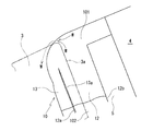
図1及び図2を参照して、本発明の実施形態に係る格納式ルーフ車用ウェザーストリップのシール構造について説明する。図1は、本発明の実施形態に係る格納式ルーフ車用ウェザーストリップのシール構造の要部を示し、図2は、図1に示すウェザーストリップとサイドウィンドガラスとの関係を示している。なお、従来例と同一部分には同一符号を付した。
本発明の実施形態に係る格納式ルーフ車のシール構造は、図4に示すように、開閉自在の幌1を折り畳んで車体後部のトランク2内に格納するタイプの車両でしかも昇降することにより開閉自在のクォーターウィンドガラス4に取付けられたウェザーストリップ10のシール構造に関する。
With reference to FIG.1 and FIG.2, the seal structure of the weather strip for retractable roof vehicles which concerns on embodiment of this invention is demonstrated. FIG. 1 shows a main part of a seal structure of a weather strip for a retractable roof vehicle according to an embodiment of the present invention, and FIG. 2 shows a relationship between the weather strip and the side window glass shown in FIG. In addition, the same code | symbol was attached | subjected to the same part as the prior art example.
As shown in FIG. 4, the seal structure of the retractable roof vehicle according to the embodiment of the present invention is a vehicle of a type in which an openable / closable hood 1 is folded and stored in a
ウェザーストリップ10は、クォーターウィンドガラス4の前側に取付けられたクォーターサッシュ5を介して取付けられるもので車体の上下方向に延び、押出成形部102の上部及び下部に上端部101と下端部(図示しない)が型成形接続されている。なお、押出成形部102の構造を示す図1のB−B線拡大断面図は、従来例で示した図6(図5のA−A線拡大断面図)と同一である。
また、ウェザーストリップ10は、主に取付基部11と中空シール部12とシールリップ部13を備えていて、特に上端部101にはシール壁30が形成されている。
The
The
取付基部11は、図6に示すように、車両の前後方向に延びる断面略板状でクォーターサッシュ5に嵌合されている。なお、ウェザーストリップ10はクォーターサッシュ5を介してクォーターウィンドガラス4の前側に取付けられるものであればよいので、クォーターサッシュ5の形状や取付基部11とクォーターサッシュ5の嵌合方法は特に限定されるものではない。例えば、テープ等により接着されていてもよい。
中空シール部12は、取付基部11の略中央部と後部から車外側に向けて膨出湾曲されるように取付基部11に一体成形されたものであり、ドアの閉時にサイドウィンドガラス3の後端部に弾接するようになっている。
シールリップ部13は、断面略舌状で取付基部11の前部から車外側に向けて突出されるように取付基部11に一体成形されたものでありその先端部13aが、同じくドアの閉時にサイドウィンドガラス3の車内側側面に弾接するようになっている。
このように、サイドウィンドガラス3は中空シール部12とシールリップ部13に弾接することによって二重にシールされるので、車外側から車内側に水Wが侵入されることが防止され、仮に水Wがサイドウィンドガラス3の後端部3aと中空シール部12の間から車内側に周り込んだとしてもシールリップ部13によって堰き止められるので、水Wは中空シール部12とシールリップ部13との間を伝わり下方に落下し車外に排出されるようになっている。
As shown in FIG. 6, the
The
The
As described above, the
また、ウェザーストリップ10は、クォーターウィンドガラス4とともに昇降し、型成形されたウェザーストリップ10の上端部101は、クォーターウィンドガラス4の上昇時(閉時)には、図1に示すように、幌1の側縁に沿って車両の前後方向に延びるように取付けられたルーフウェザーストリップ20に弾接するようになっている。
なお、ルーフウェザーストリップ20は、幌1の側縁に設けられたリテーナ(図示しない)に取付けられる取付基部21と、ウェザーストリップ10の上端部101の上端(頂部)を含めサイドウィンドガラス3及びクォーターウィンドガラス4の上端に弾接する上部中空シール部22と、ウェザーストリップ10の上端部101を含めサイドウィンドガラス3及びクォーターウィンドガラス4の車内側側面に弾接する側部中空シール部23と、車内側に延びるリップ部24を備えるが、上部中空シール部22を設けないようにしたり、側部中空シール部23を断面略舌状のシールリップ部にするなどその形状に限定されるものではない。
Further, the
The
そして、ウェザーストリップ10の上端部101に車内側から上端部101の前側角部P(押出成形部102における中空シール部12の前端12aの延長上)を覆い車外側に突出形成されサイドウィンドガラス3に車内側から弾接するシール壁30を形成している。シール壁30は、車内側から前側角部Pを覆うように車外側に折り返された状態であり、折り返しにより生じるシール壁30の車外側周縁31は、前側角部Pから後側に距離S分離れた位置(押出成形部102における中空シール部12の後端12bの延長上)から、前側角部Pの上方をとおり斜め前方に下降させられ、シールリップ部13の上端(前側角部Pと略同じ高さ)13Xから所定距離T分(幌1の閉時に外から視認できる位置)、下方位置の内側まで延設されている。シール壁30の突出長は下方位置では漸次小さくなり収束している。シール壁30の車外側周縁31の下方位置は、シールリップ部13の内側からシールリップ部13の先端部13aまで車外側に突出させてもよいが、ここでは、シールリップ部13の先端部13aより車内側に少し引っ込んだ位置までするにとどまり、先端部13との間に導かれた水Wを落下させるためのスペースを確保している。なお、本実施形態では、距離Sと所定距離Tを略同じ長さにしている(両者は種々の比率にすることができる)ので、折り返されたシール壁30は略二等辺三角形のような形状になっている。
The
また、シール壁30をウェザーストリップ10の上端部101に対して隙間を生じないように重ねて密着させることもできるが、本実施形態では、前側角部Pの上方にてシール壁30と上端部101との間に隙間Qを形成するようにシール壁30を上端部101から浮かせて、サイドウィンドガラス3の後端部3aが弾接したときにシール壁30が撓むようにしている。
また、シールリップ部13の上端13Xは、延設方向並びに厚み方向に先細にされていてシール壁30から前方に離間させられていて、シールリップ部13の上端13Xとシール壁30は二股化されていて両者の間には略V字状の溝Mが形成されている。
Further, the
Further, the
このように構成された本発明の実施形態に係る格納式ルーフ車両のシール構造によれば、ウェザーストリップ10の上端部はルーフウェザーストリップ20に弾接するとともにサイドウィンドガラス3にも弾接するためウェザーストリップ10が撓んで、図2に示すように、幌1の側端に流れ落ちた雨水や直接かけられる洗車の高圧水といった水Wが、車外側からサイドウィンドガラス3とウェザーストリップ10の上端部101との間に回り込む場合があるが、その回り込む部分にはシール壁30が形成されているので、回り込んだ水Wはシール壁30の内側に堰き止められ、あるいはシール壁30の車外側周縁31を伝わりシールリップ部13の内側に導かれる。
また、回り込んだ水Wがシール壁30をさらに越えたとしてもシール壁30とは独立して設けられたシールリップ部13の上端13X(上端13Xも上部中空シール部22に弾接している)によって堰き止められるので、水Wはシール壁30とシールリップ部13の上端13Xとの間の溝Mを伝わりシールリップ部13の内側に導かれる。
そして、シールリップ部13の内側に導かれた水Wは落下し、最終的に車外に向けて排出される。
According to the seal structure of the retractable roof vehicle according to the embodiment of the present invention configured as described above, the
Further, even if the water W that has passed around further exceeds the
Then, the water W guided to the inside of the
なお、本実施形態では、シール壁30に対してシールリップ部13の上端13Xを離間させて二股状にしたが、図3に示すように、シール壁30の車外側周縁31を上方から斜め前方に下降させシールリップ部13の上端に連設させるようにしてもよい。
これによれば、幌1の側端に流れ落ちた雨水や直接かけられる洗車の高圧水といった水Wが、車外側からサイドウィンドガラス3とウェザーストリップ10の上端部101との間に回り込んだ場合、回り込んだ水Wはシール壁30の内側に堰き止められ、あるいはシール壁30の車外側周縁31を伝わりシールリップ部13の内側に導かれる。
なお、回り込んだ水Wがシール壁30をさらに越えた場合には車内側に多少水Wが侵入することもあり、先に示した実施形態と比較してシール性に劣るが、従来例(図7)で示したようにシール壁30を設けない場合と比較すると格段的にシール機能に優れ、車内側に侵入する水Wの量を抑えることができる。
In the present embodiment, the
According to this, when water W such as rain water that has flowed down to the side end of the hood 1 or high-pressure water directly applied to the car wash enters between the
In addition, when the water W that has passed around further exceeds the
1 幌(ルーフ)
2 トランク
3 サイドウィンドガラス
3a 後端部
4 クォーターウィンドガラス
5 クォーターサッシュ
10 ウェザーストリップ
11 取付基部
12 中空シール部
12a 前端
12b 後端
13 シールリップ部
13a 先端部
13X 上端
20 ルーフウェザーストリップ
21 取付基部
22 上部中空シール部
23 側部中空シール部
24 リップ部
30 シール壁
31 車外側周縁
101 上端部(型成形部)
102 押出成形部
M 溝
P
Q
W 水
1 Top (roof)
2
102 Extrusion part M Groove P
Q
W Water
Claims (3)
前記型成形された上端部に、車内側から前記上端部の前側角部を覆い車外側に突出形成され前記サイドウィンドガラスに車内側から弾接するシール壁を形成したことを特徴とする格納式ルーフ車用ウェザーストリップのシール構造。 A mounting base mounted on a quarter sash provided on the front side of a quarter window glass of a retractable roof vehicle, and a mounting base that can be raised and lowered together with the quarter window glass, and a hollow seal that is integrally formed with the mounting base and elastically contacts the rear end of the side window glass And a seal lip portion that is integrally formed with the mounting base in front of the hollow seal portion and elastically contacts the inner side surface of the side window glass, and the molded upper end portion is attached along the side edge of the roof. A weather strip sealing structure that elastically contacts a roof weather strip extending in the longitudinal direction of the vehicle,
A retractable roof characterized in that a seal wall is formed on the molded upper end portion so as to cover the front corner portion of the upper end portion from the inside of the vehicle and project outwardly from the vehicle, and to elastically contact the side window glass from the inside of the vehicle. Car weather strip seal structure.
Priority Applications (3)
| Application Number | Priority Date | Filing Date | Title |
|---|---|---|---|
| JP2010285895A JP5705530B2 (en) | 2010-12-22 | 2010-12-22 | Weather strip seal structure for retractable roof vehicles |
| EP11189122.2A EP2468552B1 (en) | 2010-12-22 | 2011-11-15 | Sealing structure of weather strip for retractable roof vehicles |
| US13/299,024 US8782955B2 (en) | 2010-12-22 | 2011-11-17 | Sealing structure of weather strip for retractable roof vehicles |
Applications Claiming Priority (1)
| Application Number | Priority Date | Filing Date | Title |
|---|---|---|---|
| JP2010285895A JP5705530B2 (en) | 2010-12-22 | 2010-12-22 | Weather strip seal structure for retractable roof vehicles |
Publications (2)
| Publication Number | Publication Date |
|---|---|
| JP2012131399A true JP2012131399A (en) | 2012-07-12 |
| JP5705530B2 JP5705530B2 (en) | 2015-04-22 |
Family
ID=45093357
Family Applications (1)
| Application Number | Title | Priority Date | Filing Date |
|---|---|---|---|
| JP2010285895A Active JP5705530B2 (en) | 2010-12-22 | 2010-12-22 | Weather strip seal structure for retractable roof vehicles |
Country Status (3)
| Country | Link |
|---|---|
| US (1) | US8782955B2 (en) |
| EP (1) | EP2468552B1 (en) |
| JP (1) | JP5705530B2 (en) |
Families Citing this family (8)
| Publication number | Priority date | Publication date | Assignee | Title |
|---|---|---|---|---|
| DE102014100147B4 (en) * | 2013-01-14 | 2019-07-04 | GM Global Technology Operations LLC (n. d. Gesetzen des Staates Delaware) | Sealing system for a frameless door of a vehicle |
| US8898958B2 (en) | 2013-01-14 | 2014-12-02 | GM Global Technology Operations LLC | Sealing system for a frameless door of a vehicle |
| US9475364B2 (en) * | 2013-10-14 | 2016-10-25 | Magna Mirrors Of America, Inc. | Sealing system for movable window of rear window assembly |
| JP6301848B2 (en) * | 2015-02-02 | 2018-03-28 | 西川ゴム工業株式会社 | Non-fixed roof seal structure |
| EP3118040A1 (en) * | 2015-07-15 | 2017-01-18 | AGC Glass Europe | Division set of a car, assembly of the division set with a frameless window and another adjacent window of a car, and process for manufacturing the set and the assembly |
| JP2017077850A (en) * | 2015-10-22 | 2017-04-27 | 本田技研工業株式会社 | Door seal structure |
| JP6749800B2 (en) * | 2016-06-28 | 2020-09-02 | 西川ゴム工業株式会社 | Weather Strip |
| US10300777B2 (en) * | 2017-04-11 | 2019-05-28 | Ford Global Technologies, Llc | Truck tailgate system |
Citations (5)
| Publication number | Priority date | Publication date | Assignee | Title |
|---|---|---|---|---|
| JPS57130822A (en) * | 1981-02-06 | 1982-08-13 | Nissan Motor Co Ltd | Center seal structure of sashless door type car |
| JPS62156016U (en) * | 1986-03-26 | 1987-10-03 | ||
| JPS6452523A (en) * | 1987-08-20 | 1989-02-28 | Kinugawa Rubber Ind | Center seal construction for automobile |
| JPH047919U (en) * | 1990-05-11 | 1992-01-24 | ||
| JP2008285067A (en) * | 2007-05-18 | 2008-11-27 | Nishikawa Rubber Co Ltd | Automobile division bar |
Family Cites Families (15)
| Publication number | Priority date | Publication date | Assignee | Title |
|---|---|---|---|---|
| US2451399A (en) * | 1945-10-03 | 1948-10-12 | Ralph V Martin | Rain gutter for automobile windows |
| JPS6025520U (en) * | 1983-07-29 | 1985-02-21 | トヨタ自動車株式会社 | car door structure |
| JPH0710968Y2 (en) * | 1988-12-13 | 1995-03-15 | 豊田合成株式会社 | Automotive weather strip |
| US5269101A (en) * | 1991-07-29 | 1993-12-14 | Toyoda Gosei Co., Ltd. | Automotive weatherstrip |
| JP2952564B2 (en) * | 1995-07-25 | 1999-09-27 | 西川ゴム工業株式会社 | Glass run |
| US5846463A (en) * | 1996-06-13 | 1998-12-08 | Kingston-Warren Corporation | Encapsulated fixed window module for a motor vehicle |
| US6395355B1 (en) * | 1997-10-30 | 2002-05-28 | Toyoda Gosei Co., Ltd. | Weather strip |
| DE29901918U1 (en) * | 1999-02-04 | 2000-03-16 | Baedje K H Meteor Gummiwerke | Frame sealing profile |
| DE19926955B4 (en) * | 1999-06-14 | 2004-09-30 | Metzeler Automotive Profile Systems Gmbh | Bridge cap made of rubber-elastic material |
| GB2363816B (en) * | 2000-04-27 | 2002-08-28 | Toyoda Gosei Company Ltd | Weather strip |
| US6931790B2 (en) * | 2003-02-28 | 2005-08-23 | Nishikawa Rubber Co., Ltd. | Sealing structure including a water receiver for an automobile |
| JP4140522B2 (en) * | 2003-06-10 | 2008-08-27 | 豊田合成株式会社 | Weather strip, manufacturing method thereof and mold apparatus thereof |
| JP4251998B2 (en) * | 2004-01-23 | 2009-04-08 | 豊田合成株式会社 | Roof weather strip for convertible cars |
| DE202008006050U1 (en) * | 2008-05-02 | 2008-07-10 | Meteor Gummiwerke K.H. Bädje GmbH & Co. KG | sealing arrangement |
| JP5337444B2 (en) * | 2008-10-09 | 2013-11-06 | 日産自動車株式会社 | Vehicle drainage structure |
-
2010
- 2010-12-22 JP JP2010285895A patent/JP5705530B2/en active Active
-
2011
- 2011-11-15 EP EP11189122.2A patent/EP2468552B1/en active Active
- 2011-11-17 US US13/299,024 patent/US8782955B2/en not_active Expired - Fee Related
Patent Citations (5)
| Publication number | Priority date | Publication date | Assignee | Title |
|---|---|---|---|---|
| JPS57130822A (en) * | 1981-02-06 | 1982-08-13 | Nissan Motor Co Ltd | Center seal structure of sashless door type car |
| JPS62156016U (en) * | 1986-03-26 | 1987-10-03 | ||
| JPS6452523A (en) * | 1987-08-20 | 1989-02-28 | Kinugawa Rubber Ind | Center seal construction for automobile |
| JPH047919U (en) * | 1990-05-11 | 1992-01-24 | ||
| JP2008285067A (en) * | 2007-05-18 | 2008-11-27 | Nishikawa Rubber Co Ltd | Automobile division bar |
Also Published As
| Publication number | Publication date |
|---|---|
| JP5705530B2 (en) | 2015-04-22 |
| EP2468552B1 (en) | 2016-04-20 |
| US8782955B2 (en) | 2014-07-22 |
| EP2468552A3 (en) | 2015-04-29 |
| US20120159861A1 (en) | 2012-06-28 |
| EP2468552A2 (en) | 2012-06-27 |
Similar Documents
| Publication | Publication Date | Title |
|---|---|---|
| JP5705530B2 (en) | Weather strip seal structure for retractable roof vehicles | |
| JP5711528B2 (en) | Weatherstrip drainage structure | |
| US8869457B2 (en) | Assembly structure of weather strip | |
| JP4925918B2 (en) | Door weather strip | |
| JP6062746B2 (en) | Vehicle door belt line mall | |
| US20050279027A1 (en) | Weatherstrip | |
| JP5031629B2 (en) | Door weather strip | |
| JP5587162B2 (en) | Weatherstrip drainage structure | |
| JP4930788B2 (en) | Door weather strip | |
| JP4364707B2 (en) | Door glass seal structure | |
| JP4973575B2 (en) | Frameless door seal structure | |
| JP5634279B2 (en) | Automotive door seal structure | |
| JP5548507B2 (en) | Door weather strip | |
| JP5327114B2 (en) | Vehicle back door structure | |
| JP6306949B2 (en) | Weather strip for automobile | |
| KR100873556B1 (en) | Backdoor seal structure | |
| JP4716187B2 (en) | Automobile door seal structure | |
| JP2009006823A (en) | Roof side weather strip for automobile | |
| JP2007302149A (en) | Die-molded part for roof side weather strip and connection structure for cab side weather strip | |
| JP2005263057A (en) | Seal structure of automobile door | |
| JP2010036590A (en) | Seal structure of frameless door | |
| JP4540553B2 (en) | Seal structure under the rear pillar of a convertible car | |
| JP2009012725A (en) | Drain structure of retractable roof vehicle | |
| JP2005263059A (en) | Seal structure of automobile door | |
| KR19980057754A (en) | Coupling device for vehicle door weather strip |
Legal Events
| Date | Code | Title | Description |
|---|---|---|---|
| A621 | Written request for application examination |
Free format text: JAPANESE INTERMEDIATE CODE: A621 Effective date: 20131003 |
|
| A977 | Report on retrieval |
Free format text: JAPANESE INTERMEDIATE CODE: A971007 Effective date: 20140717 |
|
| A131 | Notification of reasons for refusal |
Free format text: JAPANESE INTERMEDIATE CODE: A131 Effective date: 20140722 |
|
| A521 | Request for written amendment filed |
Free format text: JAPANESE INTERMEDIATE CODE: A523 Effective date: 20140903 |
|
| TRDD | Decision of grant or rejection written | ||
| A01 | Written decision to grant a patent or to grant a registration (utility model) |
Free format text: JAPANESE INTERMEDIATE CODE: A01 Effective date: 20150217 |
|
| A61 | First payment of annual fees (during grant procedure) |
Free format text: JAPANESE INTERMEDIATE CODE: A61 Effective date: 20150225 |
|
| R150 | Certificate of patent or registration of utility model |
Ref document number: 5705530 Country of ref document: JP Free format text: JAPANESE INTERMEDIATE CODE: R150 |
|
| R250 | Receipt of annual fees |
Free format text: JAPANESE INTERMEDIATE CODE: R250 |
|
| R250 | Receipt of annual fees |
Free format text: JAPANESE INTERMEDIATE CODE: R250 |
|
| R250 | Receipt of annual fees |
Free format text: JAPANESE INTERMEDIATE CODE: R250 |
|
| R250 | Receipt of annual fees |
Free format text: JAPANESE INTERMEDIATE CODE: R250 |
|
| R250 | Receipt of annual fees |
Free format text: JAPANESE INTERMEDIATE CODE: R250 |
|
| R250 | Receipt of annual fees |
Free format text: JAPANESE INTERMEDIATE CODE: R250 |
|
| R250 | Receipt of annual fees |
Free format text: JAPANESE INTERMEDIATE CODE: R250 |