JP2012123776A - Switch of clutch pedal for vehicle - Google Patents
Switch of clutch pedal for vehicle Download PDFInfo
- Publication number
- JP2012123776A JP2012123776A JP2011129978A JP2011129978A JP2012123776A JP 2012123776 A JP2012123776 A JP 2012123776A JP 2011129978 A JP2011129978 A JP 2011129978A JP 2011129978 A JP2011129978 A JP 2011129978A JP 2012123776 A JP2012123776 A JP 2012123776A
- Authority
- JP
- Japan
- Prior art keywords
- elastic piece
- fixed contact
- contact
- movable
- elastic
- Prior art date
- Legal status (The legal status is an assumption and is not a legal conclusion. Google has not performed a legal analysis and makes no representation as to the accuracy of the status listed.)
- Withdrawn
Links
Images
Classifications
-
- B—PERFORMING OPERATIONS; TRANSPORTING
- B60—VEHICLES IN GENERAL
- B60K—ARRANGEMENT OR MOUNTING OF PROPULSION UNITS OR OF TRANSMISSIONS IN VEHICLES; ARRANGEMENT OR MOUNTING OF PLURAL DIVERSE PRIME-MOVERS IN VEHICLES; AUXILIARY DRIVES FOR VEHICLES; INSTRUMENTATION OR DASHBOARDS FOR VEHICLES; ARRANGEMENTS IN CONNECTION WITH COOLING, AIR INTAKE, GAS EXHAUST OR FUEL SUPPLY OF PROPULSION UNITS IN VEHICLES
- B60K23/00—Arrangement or mounting of control devices for vehicle transmissions, or parts thereof, not otherwise provided for
- B60K23/02—Arrangement or mounting of control devices for vehicle transmissions, or parts thereof, not otherwise provided for for main transmission clutches
-
- B—PERFORMING OPERATIONS; TRANSPORTING
- B60—VEHICLES IN GENERAL
- B60W—CONJOINT CONTROL OF VEHICLE SUB-UNITS OF DIFFERENT TYPE OR DIFFERENT FUNCTION; CONTROL SYSTEMS SPECIALLY ADAPTED FOR HYBRID VEHICLES; ROAD VEHICLE DRIVE CONTROL SYSTEMS FOR PURPOSES NOT RELATED TO THE CONTROL OF A PARTICULAR SUB-UNIT
- B60W2540/00—Input parameters relating to occupants
- B60W2540/14—Clutch pedal position
-
- B—PERFORMING OPERATIONS; TRANSPORTING
- B60—VEHICLES IN GENERAL
- B60Y—INDEXING SCHEME RELATING TO ASPECTS CROSS-CUTTING VEHICLE TECHNOLOGY
- B60Y2400/00—Special features of vehicle units
- B60Y2400/30—Sensors
- B60Y2400/301—Sensors for position or displacement
-
- H—ELECTRICITY
- H01—ELECTRIC ELEMENTS
- H01H—ELECTRIC SWITCHES; RELAYS; SELECTORS; EMERGENCY PROTECTIVE DEVICES
- H01H19/00—Switches operated by an operating part which is rotatable about a longitudinal axis thereof and which is acted upon directly by a solid body external to the switch, e.g. by a hand
- H01H19/54—Switches operated by an operating part which is rotatable about a longitudinal axis thereof and which is acted upon directly by a solid body external to the switch, e.g. by a hand the operating part having at least five or an unspecified number of operative positions
- H01H19/60—Angularly-movable actuating part carrying no contacts
- H01H19/63—Contacts actuated by axial cams
-
- H—ELECTRICITY
- H01—ELECTRIC ELEMENTS
- H01H—ELECTRIC SWITCHES; RELAYS; SELECTORS; EMERGENCY PROTECTIVE DEVICES
- H01H21/00—Switches operated by an operating part in the form of a pivotable member acted upon directly by a solid body, e.g. by a hand
- H01H21/02—Details
- H01H21/18—Movable parts; Contacts mounted thereon
- H01H21/22—Operating parts, e.g. handle
- H01H21/24—Operating parts, e.g. handle biased to return to normal position upon removal of operating force
- H01H21/26—Operating parts, e.g. handle biased to return to normal position upon removal of operating force adapted for operation by a part of the human body other than the hand, e.g. by foot
Landscapes
- Engineering & Computer Science (AREA)
- Chemical & Material Sciences (AREA)
- Combustion & Propulsion (AREA)
- Transportation (AREA)
- Mechanical Engineering (AREA)
- Mechanical Control Devices (AREA)
- Rotary Switch, Piano Key Switch, And Lever Switch (AREA)
- Arrangement And Mounting Of Devices That Control Transmission Of Motive Force (AREA)
Abstract
Description
本発明は、車両用クラッチペダルスイッチに係り、より詳しくは、構成がより簡素化された車両用クラッチペダルスイッチに関する。 The present invention relates to a vehicle clutch pedal switch, and more particularly to a vehicle clutch pedal switch with a simplified configuration.
一般的に、車両のクラッチペダルには、クラッチペダルの作動状態によってオン/オフ動作するイグニッションロックスイッチ(ignition lock switch)とニュートラルスイッチ(neutral switch)とが個別に備えられる。
イグニッションロックスイッチは、クラッチペダルを踏まない場合に始動がかかることを防止するためのものであり、ニュートラルスイッチは、クラッチペダルがフルストロークで作動したかを感知するものである。
そして、イグニッションロックスイッチおよびニュートラルスイッチの感知信号は、車両の制御ユニットに入力され、エンジンの電子的な制御が行われるようにする。
Generally, a clutch pedal of a vehicle is individually provided with an ignition lock switch and a neutral switch that are turned on / off depending on the operation state of the clutch pedal.
The ignition lock switch is for preventing start-up when the clutch pedal is not depressed, and the neutral switch is for detecting whether the clutch pedal is operated at full stroke.
The sensing signals of the ignition lock switch and the neutral switch are input to the control unit of the vehicle so that electronic control of the engine is performed.
しかし、前述した従来の構成は、ペダルのアームにイグニッションロックスイッチおよびニュートラルスイッチが打撃されてセンシングされる構造であり、その作動過程で打撃騒音が発生するという問題があった。また、イグニッションロックスイッチおよびニュートラルスイッチが個別に取り付けられることにより、構成が複雑化し、製造コストが上昇するという問題があった。 However, the conventional configuration described above has a structure in which an ignition lock switch and a neutral switch are hit and sensed by a pedal arm, and there is a problem that a hitting noise is generated in the operation process. In addition, since the ignition lock switch and the neutral switch are individually attached, there is a problem that the configuration becomes complicated and the manufacturing cost increases.
本発明は、構成が簡単で、騒音が発生しない車両用クラッチペダルスイッチの提供を目的とする。 An object of the present invention is to provide a clutch pedal switch for a vehicle that has a simple configuration and does not generate noise.
本発明は、第1固定接点と第2固定接点が互いに離隔して突出するスイッチボディと、前記第1固定接点の位置に設けられ、前記第1固定接点の方向に弾性力を提供して前記第1固定接点と選択的に接触する第1可動接点を備えた第1弾性片と、前記第2固定接点の位置に設けられ、前記第2固定接点の方向に弾性力を提供して前記第2固定接点と選択的に接触する第2可動接点を備えた第2弾性片と、前記第1固定接点と前記第2固定接点との間でペダルの回転によって共に回転し、回転時に前記第1弾性片および前記第2弾性片に加圧力を伝達して、前記第1および第2固定接点と前記第1および第2可動接点を選択的に接触させる回転体と、前記第1弾性片および前記第2弾性片に連結され、前記第1および第2固定接点と前記第1および第2可動接点の接触信号を伝達するターミナルとを含むことを特徴とする。 The present invention provides a switch body in which a first fixed contact and a second fixed contact protrude apart from each other, a position of the first fixed contact, and provides an elastic force in the direction of the first fixed contact. A first elastic piece having a first movable contact that selectively contacts the first fixed contact; and a second elastic contact provided at a position of the second fixed contact to provide an elastic force in the direction of the second fixed contact. The second elastic piece having a second movable contact selectively contacting the two fixed contacts and the first fixed contact and the second fixed contact are rotated together by the rotation of the pedal, and the first elastic member is rotated during the rotation. A rotating body that transmits pressure to the elastic piece and the second elastic piece to selectively contact the first and second fixed contacts and the first and second movable contacts; the first elastic piece and the A first elastic piece connected to the second elastic piece; Characterized in that it comprises a terminal for transmitting a contact signal of beauty second movable contact.
前記回転体は、前記ペダルに形成される係止突起が移動する長方形のホールが形成され、前記ペダルの回転力を受けて回転する第1回転部と、前記第1回転部の回転と共に回転し、前記第1および第2弾性片に加圧力を伝達する第2回転部とを含むことを特徴とする。 The rotating body is formed with a rectangular hole through which a locking projection formed on the pedal moves, and rotates with the rotation of the first rotating portion and a first rotating portion that rotates in response to the rotational force of the pedal. And a second rotating part for transmitting a pressing force to the first and second elastic pieces.
前記第2回転部は、前記第1回転部に連結される回転ボディと、前記回転ボディの側面に突出し、前記第1および第2弾性片の弾性力を克服する加圧力を伝達する加圧突出部とを含むことを特徴とする。 The second rotating part includes a rotating body connected to the first rotating part, and a pressure protrusion that protrudes from a side surface of the rotating body and transmits a pressing force that overcomes the elastic force of the first and second elastic pieces. Part.
前記加圧突出部は、前記回転ボディの外側の一部に沿ってラウンド状に突出し、前記第1弾性片と前記第2弾性片が載置される載置突部と、前記載置突部の一側に形成され、前記回転ボディの回転時に前記第1弾性片がスライドされる第1傾斜部と、前記載置突部の他側に形成され、前記回転ボディの回転時に前記第2弾性片がスライドされる第2傾斜部とを含むことを特徴とする。 The pressure protrusion protrudes in a round shape along a part of the outer side of the rotating body, and a mounting protrusion on which the first elastic piece and the second elastic piece are mounted; A first inclined portion formed on one side of the rotating body and on which the first elastic piece is slid, and the second elastic member formed on the other side of the mounting protrusion. And a second inclined portion on which the piece is slid.
前記ペダルストロークのアイドル状態において、前記第1弾性片は前記載置突部の外側に位置し、前記第1固定接点と前記第1可動接点は接触した状態であり、前記第2弾性片は前記載置突部の上側に位置し、前記第2固定接点と前記第2可動接点は分離された状態であり、前記ペダルの50%のストロークにおいて、
前記第1弾性片は前記第1傾斜面に位置し、前記第1固定接点と前記第1可動接点は分離された状態であり、前記第2弾性片は前記第2傾斜面に位置し、前記第2固定接点と前記第2可動接点は分離された状態であり、前記ペダルの85%以上のストローク範囲においては、前記第1弾性片は前記載置突部上に位置し、前記第1固定接点と前記第1可動接点は分離された状態であり、前記第2弾性片は前記載置突部の外側に位置し、前記第2固定接点と前記第2可動接点は接触した状態であることを特徴とする。
In the idle state of the pedal stroke, the first elastic piece is positioned outside the mounting protrusion, the first fixed contact and the first movable contact are in contact, and the second elastic piece is the front Located above the mounting protrusion, the second fixed contact and the second movable contact are separated, and in a 50% stroke of the pedal,
The first elastic piece is located on the first inclined surface, the first fixed contact and the first movable contact are separated, and the second elastic piece is located on the second inclined surface, The second fixed contact and the second movable contact are separated from each other, and in the stroke range of 85% or more of the pedal, the first elastic piece is located on the mounting protrusion, and the first fixed contact The contact and the first movable contact are separated from each other, the second elastic piece is positioned outside the mounting protrusion, and the second fixed contact and the second movable contact are in contact with each other. It is characterized by.
本発明によれば、イグニッションロックスイッチおよびニュートラルスイッチを削除することにより、作動過程で騒音が発生せず、構成部品がより簡素化され、製造コストを節減することができる。 According to the present invention, by eliminating the ignition lock switch and the neutral switch, no noise is generated in the operation process, the components are further simplified, and the manufacturing cost can be reduced.
以下、本発明の実施形態にかかる車両用クラッチペダルスイッチについて、添付した図面を参照して詳細に説明する。
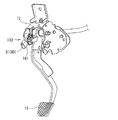
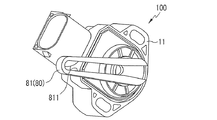
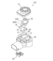
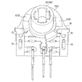
図1は、本発明の一実施形態にかかる車両用クラッチペダルスイッチが設けられた状態を概略的に示す斜視図であり、図2は、図1の車両用クラッチペダルスイッチを概略的に示す斜視図であり、図3は、図2の車両用クラッチペダルスイッチの主部を分解して示す分解斜視図である。
図1〜図3に示すように、本発明の一実施形態にかかる車両用クラッチペダルスイッチ100は、ハウジング11の内部に設けられ、第1および第2固定接点10、20が突出するスイッチボディ30と、第1固定接点10と選択的に接触する第1可動接点40が設けられた第1弾性片50と、第2固定接点20と選択的に接触する第2可動接点60が設けられた第2弾性片70と、第1および第2固定接点10、20と第1および第2可動接点40、60の接触を制御する回転体80と、第1および第2固定接点10、20と第1および第2可動接点40、60の接触信号を伝達するターミナル90とを含む。符号18は、ハウジング11に結合されるカバーを表す。
Hereinafter, a clutch pedal switch for a vehicle according to an embodiment of the present invention will be described in detail with reference to the accompanying drawings.
FIG. 1 is a perspective view schematically showing a state in which a vehicle clutch pedal switch according to an embodiment of the present invention is provided, and FIG. 2 is a perspective view schematically showing the vehicle clutch pedal switch of FIG. FIG. 3 is an exploded perspective view showing the main part of the vehicle clutch pedal switch of FIG. 2 in an exploded manner.
As shown in FIGS. 1 to 3, a vehicle
スイッチボディ30は、車体12に取り付けられるハウジング11の内部に載置される。スイッチボディ30は、第1および第2固定接点10、20が突出する。第1および第2固定接点10、20は、スイッチボディ30の一側と他側の位置で互いに離隔して設置可能である。このような第1および第2固定接点10、20は、導電体の導電プレート14によってターミナル90に接続される。
ターミナル90での信号の伝達過程は、以下、第1および第2固定接点10、20と第1および第2可動接点40、60のセンシング作動を説明しながらより具体的に説明する。第1および第2固定接点10、20が設けられた位置には、第1および第2弾性片50、70が設けられる。
The
Hereinafter, the signal transmission process at the
第1弾性片50は、第1固定接点10が設けられた近接位置に設けられる。第1弾性片50は、一端が第1固定接点10の近接位置に固定され、他端は折り曲げられて第1固定接点10の方向に延びる。このような第1弾性片50には、第1固定接点10の方向に突出するように第1可動接点40が設けられる。これにより、第1弾性片50に外力が作用しない場合には、第1弾性片50の弾性力によって第1固定接点10と第1可動接点40は互いに接触した状態を維持する。
The first
第2弾性片70は、第2固定接点20が設けられた近接位置に設けられる。第2弾性片70は、一端が第2固定接点20の近接位置に固定され、他端は折り曲げられて第2固定接点20の方向に延びる。このような第2弾性片70には、第2固定接点20の方向に突出するように第2可動接点60が設けられる。これにより、第2弾性片70に外力が作用しない場合には、第2弾性片70の弾性力によって第2固定接点20と第2可動接点60は互いに接触した状態を維持する。
前述した第1および第2固定接点10、20と第1および第2可動接点40、60相互間の接触解除は、回転体80の回転作動によって発生する。
The second
The contact release between the first and second
回転体80は、第1固定接点10と第2固定接点20との間でペダル16の回転によって共に回転する。回転体80は、その回転時に第1弾性片50および第2弾性片70に加圧力を伝達して、第1および第2固定接点10、20と第1および第2可動接点40、60の接触を選択的に制限する。
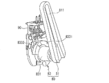
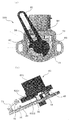
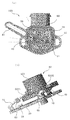
図4は、ハウジングを除去した状態における車両用クラッチペダルスイッチを概略的に示す斜視図であり、図5は、図4における第1回転部を除去した状態を概略的に示す斜視図である。
図4および図5を参照して回転体80についてより具体的に説明する。
回転体80は、ペダル16の回転力を受ける第1回転部81と、第1回転部81に結合されて共に回転し、第1および第2弾性片50、70に加圧力を伝達する第2回転部83とを含む。
The rotating
4 is a perspective view schematically showing the vehicle clutch pedal switch with the housing removed, and FIG. 5 is a perspective view schematically showing a state in which the first rotating portion in FIG. 4 is removed.
The rotating
The
第1回転部81は、ペダル16の踏力の伝達に応じた回転力を第2回転部83に伝達するためのものであって、その長手方向に長方形のホール811が形成される。即ち、ペダル16には突起部161が形成され、この突起部161は、第1回転部81の長方形のホール811に挿入される。したがって、ペダル16が踏力の伝達によって回転すると、第1回転部81には、突起部161がホール811にスライドされることによって回転力が発生する。このような第1回転部81の回転力は第2回転部83に伝達される。第1回転部81と第2回転部83は、一体に形成されることも可能であり、押し込み結合による嵌め合いで着脱可能に結合されることも可能である。本実施形態では、第1回転部81と第2回転部83が嵌め合いで着脱可能に結合されることを例示する。
The first
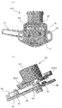
第2回転部83は、第1回転部81に連結される回転ボディ831と、回転ボディ831の側面に突出し、第1および第2弾性片50、70の弾性力を克服する加圧力を伝達する加圧突出部833(8331+8335)とを含む。
回転ボディ831は、第1回転部81と連結される部分に円筒状に突出することができる。回転ボディ831と第1回転部81は嵌め合いで着脱可能に結合可能である。
加圧突出部833(8331+8335)は、回転ボディ831の側面からラウンド状に突出することができる。より具体的に加圧突出部833(8331+8335)について説明すると、加圧突出部833(8331+8335)は、回転ボディ831の外側の一部に沿ってラウンド状に突出する載置突部8331と、載置突部8331の一側に形成される第1傾斜部8333と、載置突部8331の他側に形成される第2傾斜部8335とを含む。
The second
The
The pressure protrusion 833 (8331 + 8335) can protrude from the side surface of the
載置突部8331は、第1弾性片50と第2弾性片70が回転体80の回転によって選択的に載置される部分である。第1弾性片50が載置突部8331上に位置すると、第1固定接点10と第1可動接点40は互いに接触しない状態で離隔する。そして、第2弾性片70が載置突部8331上に位置すると、第2固定接点20と第2可動接点60は互いに接触しない状態で離隔する。
第1傾斜部8333とは、回転体80の回転によって第1弾性片50の端部がスライドされる部分をいう。より具体的に説明すると、第1傾斜部8333は、回転体80の一方向または他方向への回転時に、第1弾性片50の端部を載置突部8331上に移動させるか、載置突部8331の外側へと移動をガイドする部分をいう。
The mounting
The first
第2傾斜部8335とは、回転体80の回転によって第2弾性片70の端部がスライドされる部分をいう。より具体的に説明すると、第2傾斜部8335は、回転体80の一方向または他方向への回転時に、第2弾性片70の端部を載置突部8331上に移動させるか、載置突部8331の外側へと移動をガイドする部分をいう。
前述したように、回転体80は、その回転によって第1弾性片50または第2弾性片70に加圧力を伝達して、第1弾性片50および第2弾性片70を第1および第2固定接点10、20と選択的に接触させる。これは、クラッチペダル16の作動に応じた作動信号をECUに選択的に伝達するためのものである。これについては、以下、図6(a)〜図8(b)を参照してより詳細に説明する。
The second
As described above, the rotating
図6(a)は、車両のアイドル状態における車両用クラッチペダルスイッチの作動状態を概略的に示す平面図であり、図6(b)は、図6(a)の車両用クラッチペダルの作動状態を概略的に示す側面図である。
図6(a)および(b)に示すように、車両のアイドル状態においては、第1弾性片50は載置突部8331の外側に位置し、第1 固定接点10と第1可動接点40は接触した状態である。そして、第2弾性片70は載置突部8331の上側に位置し、第2固定接点20と第2可動接点60は分離された状態である。このような状態は、車両の変速機に伝達されるエンジンの動力が連結される状態である。
FIG. 6A is a plan view schematically showing an operation state of the vehicle clutch pedal switch in an idle state of the vehicle, and FIG. 6B is an operation state of the vehicle clutch pedal in FIG. FIG.
As shown in FIGS. 6A and 6B, when the vehicle is in an idle state, the first
図7(a)は、車両用クラッチペダルの総ストロークで50%のストローク状態の車両用クラッチペダルスイッチの作動状態を概略的に示す平面図であり、図7(b)は、図7(a)の車両用クラッチペダルの作動状態を概略的に示す側面図である。
図7(a)および(b)に示すように、車両用クラッチペダルが総ストロークの50%のストロークで踏力が伝達されて回転した状態においては、第1弾性片50は第1傾斜部8333に位置し、第1固定接点10と第1可動接点40は分離された状態である。そして、第2弾性片70は第2傾斜部8335に位置し、第2固定接点20と第2可動接点60は分離された状態である。前述した状態は、車両の変速機に伝達されるエンジンの動力が遮断される状態を表す。
FIG. 7A is a plan view schematically showing an operating state of the vehicle clutch pedal switch in a stroke state of 50% of the total stroke of the vehicle clutch pedal, and FIG. 7B is a plan view of FIG. 2) is a side view schematically showing an operating state of the vehicle clutch pedal.
As shown in FIGS. 7A and 7B, in the state where the pedal force is transmitted and the vehicle clutch pedal is rotated at a stroke of 50% of the total stroke, the first
図8(a)は、車両用クラッチペダルの総ストロークの85%のストローク状態の車両用クラッチペダルスイッチの作動状態を概略的に示す平面図であり、図8(b)は、(a)の車両用クラッチペダルの作動状態を概略的に示す側面図である。
図8(a)および(b)に示すように、車両用クラッチペダルの85%以上のストローク状態においては、第1弾性片50は載置突部8331上に位置し、第1固定接点10と第1可動接点40は分離された状態である。そして、第2弾性片70は載置突部8331の外側に位置し、第2固定接点20と第2可動接点60は接触した状態である。このような状態は、車両のイグニッションロック(ignition rock)が解除された状態で車両の始動が可能な状態を表す。
FIG. 8A is a plan view schematically showing an operating state of the vehicle clutch pedal switch in a stroke state of 85% of the total stroke of the vehicle clutch pedal. FIG. 8B is a plan view of FIG. It is a side view which shows roughly the operation state of the clutch pedal for vehicles.
As shown in FIGS. 8A and 8B, in the stroke state of 85% or more of the vehicle clutch pedal, the first
本発明の実施形態で詳細に説明した通り、本発明の車両用クラッチペダルスイッチは、ペダルの踏力に応じた回転体80の回転角度に応じて第1および第2弾性片50、70が第1および第2傾斜部8333、8335の加圧力の伝達によって選択的に持ち上げられる作用が可能である。したがって、第1および第2固定接点10、20と第1および第2可動接点40、60の選択的な接触または接触解除作用が回転体80の回転角度に応じて自動的に行われることにより、より簡単な構成でクラッチセンサの構成が可能になる。
As described in detail in the embodiment of the present invention, in the clutch pedal switch for a vehicle according to the present invention, the first and second
以上、本発明に関する好ましい実施形態を説明したが、本発明は前記実施形態に限定されず、本発明の属する技術範囲を逸脱しない範囲での全ての変更が含まれる。 As mentioned above, although preferred embodiment regarding this invention was described, this invention is not limited to the said embodiment, All the changes in the range which does not deviate from the technical scope to which this invention belongs are included.
10:第1固定接点
11:ハウジング
20:第2固定接点
30:スイッチボディ
40:第1可動接点
50:第1弾性片
60:第2可動接点
70:第2弾性片
80:回転体
81:第1回転部
83:第2回転部
831:回転ボディ
833:加圧突出部
8331:載置突部
8333:第1傾斜部
8335:第2傾斜部
10: first fixed contact 11: housing 20: second fixed contact 30: switch body 40: first movable contact 50: first elastic piece 60: second movable contact 70: second elastic piece 80: rotating body 81: first 1 rotation part 83: 2nd rotation part 831: rotation body 833: pressurization protrusion part 8331: mounting protrusion part 8333: 1st inclination part 8335: 2nd inclination part
Claims (5)
前記第1固定接点の位置に設けられ、前記第1固定接点の方向に弾性力を提供して前記第1固定接点と選択的に接触する第1可動接点を備えた第1弾性片と、
前記第2固定接点の位置に設けられ、前記第2固定接点の方向に弾性力を提供して前記第2固定接点と選択的に接触する第2可動接点を備えた第2弾性片と、
前記第1固定接点と前記第2固定接点との間でペダルの回転によって共に回転し、回転時に前記第1弾性片および前記第2弾性片に加圧力を伝達して、前記第1および第2固定接点と前記第1および第2可動接点を選択的に接触させる回転体と、
前記第1弾性片および前記第2弾性片に連結され、前記第1および第2固定接点と前記第1および第2可動接点の接触信号を伝達するターミナルとを含むことを特徴とする車両用クラッチペダルスイッチ。 A switch body in which the first fixed contact and the second fixed contact protrude apart from each other;
A first elastic piece provided with a first movable contact provided at a position of the first fixed contact and providing an elastic force in a direction of the first fixed contact to selectively contact the first fixed contact;
A second elastic piece having a second movable contact provided at a position of the second fixed contact and providing an elastic force in a direction of the second fixed contact to selectively contact the second fixed contact;
The first fixed contact and the second fixed contact are rotated together by a pedal rotation, and a pressure is transmitted to the first elastic piece and the second elastic piece during the rotation. A rotating body that selectively contacts the fixed contact and the first and second movable contacts;
A vehicle clutch connected to the first elastic piece and the second elastic piece and including a terminal for transmitting a contact signal of the first and second movable contacts and the first and second movable contacts. Pedal switch.
前記ペダルに形成される係止突起が移動する長方形のホールが形成され、前記ペダルの回転力を受けて回転する第1回転部と、
前記第1回転部の回転と共に回転し、前記第1および第2弾性片に加圧力を伝達する第2回転部とを含むことを特徴とする請求項1に記載の車両用クラッチペダルスイッチ。 The rotating body is
A rectangular hole in which a locking projection formed on the pedal moves is formed, and a first rotating part that rotates by receiving the rotational force of the pedal;
2. The vehicular clutch pedal switch according to claim 1, further comprising: a second rotating portion that rotates together with the rotation of the first rotating portion and transmits a pressure force to the first and second elastic pieces.
前記第1回転部に連結される回転ボディと、
前記回転ボディの側面に突出し、前記第1および第2弾性片の弾性力を克服する加圧力を伝達する加圧突出部とを含むことを特徴とする請求項2に記載の車両用クラッチペダルスイッチ。 The second rotating part is
A rotating body coupled to the first rotating part;
The vehicular clutch pedal switch according to claim 2, further comprising: a pressing protrusion that protrudes from a side surface of the rotating body and transmits a pressing force that overcomes an elastic force of the first and second elastic pieces. .
前記回転ボディの外側の一部に沿ってラウンド状に突出し、前記第1弾性片と前記第2弾性片が載置される載置突部と、
前記載置突部の一側に形成され、前記回転ボディの回転時に前記第1弾性片がスライドされる第1傾斜部と、
前記載置突部の他側に形成され、前記回転ボディの回転時に前記第2弾性片がスライドされる第2傾斜部とを含むことを特徴とする請求項3に記載の車両用クラッチペダルスイッチ。 The pressure protrusion is
A projecting protrusion that projects in a round shape along a part of the outer side of the rotating body, and on which the first elastic piece and the second elastic piece are placed,
A first inclined portion that is formed on one side of the mounting protrusion and on which the first elastic piece is slid during rotation of the rotating body;
4. The vehicle clutch pedal switch according to claim 3, further comprising: a second inclined portion that is formed on the other side of the mounting protrusion and on which the second elastic piece is slid when the rotating body rotates. .
前記第1弾性片は前記載置突部の外側に位置し、前記第1固定接点と前記第1可動接点は接触した状態であり、前記第2弾性片は前記載置突部の上側に位置し、前記第2固定接点と前記第2可動接点は分離された状態であり、
前記ペダルの50%のストロークにおいて、
前記第1弾性片は前記第1傾斜面に位置し、前記第1固定接点と前記第1可動接点は分離された状態であり、前記第2弾性片は前記第2傾斜面に位置し、前記第2固定接点と前記第2可動接点は分離された状態であり、
前記ペダルの85%以上のストローク範囲においては、
前記第1弾性片は前記載置突部上に位置し、前記第1固定接点と前記第1可動接点は分離された状態であり、前記第2弾性片は前記載置突部の外側に位置し、前記第2固定接点と前記第2可動接点は接触した状態であることを特徴とする請求項4に記載の車両用クラッチペダルスイッチ。
In the idle state of the pedal stroke,
The first elastic piece is located outside the placement protrusion, the first fixed contact and the first movable contact are in contact with each other, and the second elastic piece is located above the placement protrusion. The second fixed contact and the second movable contact are separated from each other;
At 50% stroke of the pedal,
The first elastic piece is located on the first inclined surface, the first fixed contact and the first movable contact are separated, and the second elastic piece is located on the second inclined surface, The second fixed contact and the second movable contact are separated from each other;
In the stroke range of 85% or more of the pedal,
The first elastic piece is located on the placement protrusion, the first fixed contact and the first movable contact are separated, and the second elastic piece is located outside the placement protrusion. The vehicle clutch pedal switch according to claim 4, wherein the second fixed contact and the second movable contact are in contact with each other.
Applications Claiming Priority (2)
| Application Number | Priority Date | Filing Date | Title |
|---|---|---|---|
| KR1020100123713A KR101261947B1 (en) | 2010-12-06 | 2010-12-06 | Switch of clutch pedal for vehicle |
| KR10-2010-0123713 | 2010-12-06 |
Publications (1)
| Publication Number | Publication Date |
|---|---|
| JP2012123776A true JP2012123776A (en) | 2012-06-28 |
Family
ID=46083034
Family Applications (1)
| Application Number | Title | Priority Date | Filing Date |
|---|---|---|---|
| JP2011129978A Withdrawn JP2012123776A (en) | 2010-12-06 | 2011-06-10 | Switch of clutch pedal for vehicle |
Country Status (5)
| Country | Link |
|---|---|
| US (1) | US8592701B2 (en) |
| JP (1) | JP2012123776A (en) |
| KR (1) | KR101261947B1 (en) |
| CN (1) | CN102485522B (en) |
| DE (1) | DE102011052226B4 (en) |
Cited By (2)
| Publication number | Priority date | Publication date | Assignee | Title |
|---|---|---|---|---|
| JP2014021791A (en) * | 2012-07-19 | 2014-02-03 | Honda Motor Co Ltd | Operation amount detector |
| WO2020235550A1 (en) * | 2019-05-21 | 2020-11-26 | 株式会社デンソー | Accelerator device |
Families Citing this family (10)
| Publication number | Priority date | Publication date | Assignee | Title |
|---|---|---|---|---|
| US8550412B2 (en) * | 2010-11-08 | 2013-10-08 | Toyota Motor Engineering And Manufacturing North America, Inc. | High load resistant stop lamp switch brackets and brake pedal assemblies incorporating the same |
| JP2013256238A (en) * | 2012-06-13 | 2013-12-26 | Yanmar Co Ltd | Vehicle with clutch pedal |
| KR101383730B1 (en) * | 2012-12-24 | 2014-04-17 | 한국오므론전장(주) | Integration switch of clutch pedal for vehicle |
| KR101509744B1 (en) * | 2013-11-20 | 2015-04-07 | 현대자동차 주식회사 | Clutch operating system |
| CN104960413A (en) * | 2015-07-14 | 2015-10-07 | 安徽安凯汽车股份有限公司 | Clutch pedal mechanism |
| US10359802B2 (en) | 2016-08-22 | 2019-07-23 | Cts Corporation | Variable force electronic vehicle clutch pedal |
| CN106585958B (en) * | 2016-11-30 | 2023-06-02 | 中国航空工业集团公司沈阳飞机设计研究所 | Self-balancing integrated central rod |
| CN111028609B (en) * | 2019-12-24 | 2024-03-22 | 吉林大学 | Pedal feel simulation device applied to driving simulator |
| KR102753900B1 (en) | 2022-03-11 | 2025-01-14 | 성한 주식회사 | IP camera-based remote inspection control system and method |
| CN121269464A (en) * | 2024-07-05 | 2026-01-06 | 安克创新科技股份有限公司 | Wire winding control method and winding mechanism |
Family Cites Families (15)
| Publication number | Priority date | Publication date | Assignee | Title |
|---|---|---|---|---|
| JP2946403B2 (en) | 1995-12-28 | 1999-09-06 | 帝国通信工業株式会社 | switch |
| DE19701637A1 (en) * | 1997-01-20 | 1998-07-23 | Mannesmann Vdo Ag | Foot-pedal-operated input with angular measurement e.g. for motor vehicle control-by-wire |
| JP4148553B2 (en) * | 1998-02-20 | 2008-09-10 | 株式会社ミクニ | Accelerator pedal mechanism for vehicles |
| DE10012179A1 (en) * | 2000-03-13 | 2001-10-04 | Methode Electronics Malta Ltd | Pedal device for a motor vehicle with a displacement sensor unit |
| JP3870748B2 (en) * | 2001-10-29 | 2007-01-24 | 松下電器産業株式会社 | Lever switch |
| KR20060070878A (en) | 2004-12-21 | 2006-06-26 | 현대자동차주식회사 | Switch assembly of vehicle clutch / brake pedal |
| JP2006214477A (en) | 2005-02-02 | 2006-08-17 | Hino Motors Ltd | Clutch operating device |
| US7202426B2 (en) * | 2005-05-02 | 2007-04-10 | Eaton Corporation | Master cylinder position switch |
| KR20060130289A (en) * | 2005-06-14 | 2006-12-19 | 현대모비스 주식회사 | Integrated switch with clutch pedal |
| DE102005048950B3 (en) * | 2005-10-13 | 2007-05-03 | Zf Friedrichshafen Ag | Control valve for clutch actuating device of motor vehicle, has valve body moved to one switching position by valve rod that is centered in initial position, where spring and magnetic forces indirectly act on rod that is pre-stressed |
| CN200999002Y (en) * | 2007-01-25 | 2008-01-02 | 重庆长安汽车股份有限公司 | Automobile clutch pedal with position perception arrangement |
| JP4989296B2 (en) * | 2007-04-27 | 2012-08-01 | 本田技研工業株式会社 | Clutch operating mechanism |
| CA2714100C (en) | 2008-02-08 | 2016-03-29 | Union Carbide Chemicals & Plastics Technology Llc | Flame-retardant polyolefin / thermoplastic polyurethane composition |
| CN101791949B (en) * | 2010-03-16 | 2013-01-23 | 重庆长安汽车股份有限公司 | System and method for detecting clutch position of hybrid power vehicle |
| CN201868294U (en) * | 2010-11-30 | 2011-06-15 | 东风汽车公司 | Clutch switch for micro hybrid vehicle |
-
2010
- 2010-12-06 KR KR1020100123713A patent/KR101261947B1/en not_active Expired - Fee Related
-
2011
- 2011-06-10 JP JP2011129978A patent/JP2012123776A/en not_active Withdrawn
- 2011-07-22 US US13/188,851 patent/US8592701B2/en not_active Expired - Fee Related
- 2011-07-28 DE DE102011052226.3A patent/DE102011052226B4/en not_active Expired - Fee Related
- 2011-07-29 CN CN201110220384.4A patent/CN102485522B/en active Active
Cited By (3)
| Publication number | Priority date | Publication date | Assignee | Title |
|---|---|---|---|---|
| JP2014021791A (en) * | 2012-07-19 | 2014-02-03 | Honda Motor Co Ltd | Operation amount detector |
| WO2020235550A1 (en) * | 2019-05-21 | 2020-11-26 | 株式会社デンソー | Accelerator device |
| JP2020189534A (en) * | 2019-05-21 | 2020-11-26 | 株式会社デンソー | Accelerator device |
Also Published As
| Publication number | Publication date |
|---|---|
| CN102485522B (en) | 2016-05-11 |
| US20120138435A1 (en) | 2012-06-07 |
| KR101261947B1 (en) | 2013-05-09 |
| KR20120062445A (en) | 2012-06-14 |
| DE102011052226B4 (en) | 2020-02-27 |
| DE102011052226A1 (en) | 2012-06-06 |
| US8592701B2 (en) | 2013-11-26 |
| CN102485522A (en) | 2012-06-06 |
Similar Documents
| Publication | Publication Date | Title |
|---|---|---|
| JP2012123776A (en) | Switch of clutch pedal for vehicle | |
| JP6231349B2 (en) | Throttle grip device | |
| US9671815B2 (en) | Electronic throttle control pedal assembly | |
| US8650984B2 (en) | Electronic clutch pedal assembly having varying resistance | |
| JP2009181711A (en) | Switch device | |
| WO2011102284A1 (en) | Switch device | |
| US7415897B2 (en) | Electronic torque wrench | |
| JP2010175297A (en) | Automatic vehicle driving device | |
| CN205900382U (en) | Automotive electronics parking switch | |
| JP5689823B2 (en) | Switch device | |
| JP2006202691A (en) | Switch device | |
| JP4969343B2 (en) | Speed change operation device for vehicle | |
| KR20050123468A (en) | Electronic pedal apparatus | |
| JP2011124144A (en) | Switch device for operation lever | |
| KR101155226B1 (en) | Switching unit | |
| TW201633913A (en) | Electric reel | |
| JP6396846B2 (en) | Rotating operation type electric parts | |
| CN217706154U (en) | Finger-dialing and electric scooter for electric scooter | |
| CN112440739B (en) | Clutch pedal device for electronic clutch systems | |
| JP3856569B2 (en) | Rotating electrical parts with push switch | |
| KR101339243B1 (en) | Clutch pedal device for vehicle | |
| CN218112908U (en) | bicycle control device | |
| JP2004308432A (en) | Engine control device | |
| KR102064565B1 (en) | Organ type accelerator pedal apparatus for vehicle | |
| JP2006228620A (en) | Steering switching device |
Legal Events
| Date | Code | Title | Description |
|---|---|---|---|
| A300 | Application deemed to be withdrawn because no request for examination was validly filed |
Free format text: JAPANESE INTERMEDIATE CODE: A300 Effective date: 20140902 |