JP2012122494A - Shock absorber - Google Patents
Shock absorber Download PDFInfo
- Publication number
- JP2012122494A JP2012122494A JP2010271119A JP2010271119A JP2012122494A JP 2012122494 A JP2012122494 A JP 2012122494A JP 2010271119 A JP2010271119 A JP 2010271119A JP 2010271119 A JP2010271119 A JP 2010271119A JP 2012122494 A JP2012122494 A JP 2012122494A
- Authority
- JP
- Japan
- Prior art keywords
- cylinder
- rod
- outer cylinder
- shock absorber
- reservoir
- Prior art date
- Legal status (The legal status is an assumption and is not a legal conclusion. Google has not performed a legal analysis and makes no representation as to the accuracy of the status listed.)
- Granted
Links
- 239000006096 absorbing agent Substances 0.000 title claims abstract description 50
- 230000035939 shock Effects 0.000 title claims abstract description 50
- 239000007788 liquid Substances 0.000 claims abstract description 28
- 238000007789 sealing Methods 0.000 claims description 4
- 238000005192 partition Methods 0.000 abstract 1
- 125000006850 spacer group Chemical group 0.000 description 10
- 238000013016 damping Methods 0.000 description 8
- 230000002093 peripheral effect Effects 0.000 description 6
- 239000000470 constituent Substances 0.000 description 3
- 239000010720 hydraulic oil Substances 0.000 description 3
- XAGFODPZIPBFFR-UHFFFAOYSA-N aluminium Chemical compound [Al] XAGFODPZIPBFFR-UHFFFAOYSA-N 0.000 description 2
- 229910052782 aluminium Inorganic materials 0.000 description 2
- 230000000740 bleeding effect Effects 0.000 description 1
- 238000004891 communication Methods 0.000 description 1
- 230000006835 compression Effects 0.000 description 1
- 238000007906 compression Methods 0.000 description 1
- 230000008602 contraction Effects 0.000 description 1
- 238000002347 injection Methods 0.000 description 1
- 239000007924 injection Substances 0.000 description 1
- 230000002452 interceptive effect Effects 0.000 description 1
- 238000012423 maintenance Methods 0.000 description 1
- 235000013372 meat Nutrition 0.000 description 1
- 238000000034 method Methods 0.000 description 1
- 230000000149 penetrating effect Effects 0.000 description 1
- 238000005096 rolling process Methods 0.000 description 1
- 239000000725 suspension Substances 0.000 description 1
- 239000013585 weight reducing agent Substances 0.000 description 1
Images
Abstract
Description
本発明は、緩衝器に関する。 The present invention relates to a shock absorber.
従来、両ロッド型に設定されて車両の車体と車軸との間に介装されるサスペンション用途で使用される緩衝器にあっては、たとえば、シリンダと、シリンダ内に移動自在に挿入されるロッドと、ロッドの中間部に設けられるとともにシリンダ内に摺動自在に挿入されて二つの圧力室を隔成するピストンと、シリンダを覆う外筒と、シリンダの下端側から突出するロッドの下端と外筒との間に配置され外筒との間にリザーバを形成する内筒と、内筒の外周および外筒の内周に摺接するとともに上記リザーバ内を気室と液室とに区画する環状のフリーピストンとを備えて構成されている。 2. Description of the Related Art Conventionally, in a shock absorber used in a suspension application that is set to a double rod type and is interposed between a vehicle body and an axle of a vehicle, for example, a cylinder and a rod that is movably inserted into the cylinder A piston that is provided in the middle of the rod and is slidably inserted into the cylinder to separate the two pressure chambers, an outer cylinder that covers the cylinder, a lower end of the rod that projects from the lower end side of the cylinder, and an outer An inner cylinder which is disposed between the cylinder and forms a reservoir with the outer cylinder; and an annular cylinder which slidably contacts the outer circumference of the inner cylinder and the inner circumference of the outer cylinder and which divides the reservoir into an air chamber and a liquid chamber And a free piston.
また、この両ロッド型の緩衝器によれば、圧力室とリザーバとを連通して、作動油温度の変化による体積変化をリザーバで補償するようにしている(たとえば、特許文献1参照)。 Further, according to the double rod type shock absorber, the pressure chamber and the reservoir are communicated with each other, and the volume change due to the change in the hydraulic oil temperature is compensated by the reservoir (for example, see Patent Document 1).
この緩衝器にあっては、両ロッド型に設定されて上記二つの圧力室内の圧力を受けるピストンの受圧面積が上下の両側で等しいので、常に伸長しようとする力、つまり、ロッドをシリンダから上方へ突出させるロッド反力を生じない。したがって、リザーバ内の圧力を高く設定して緩衝器内の作動油の見掛け上の剛性を高めても、ロッド反力が生じないので、緩衝器の減衰力発生の応答性および減衰力設定の自由度を飛躍的に高めることができる(特許文献1参照)。 In this shock absorber, since the pressure receiving area of the piston that is set to a double rod type and receives the pressure in the two pressure chambers is the same on both the upper and lower sides, the force that always tries to extend, that is, the rod is moved upward from the cylinder. No rod reaction force to project Therefore, even if the pressure in the reservoir is set high to increase the apparent rigidity of the hydraulic oil in the shock absorber, the rod reaction force does not occur. The degree can be dramatically increased (see Patent Document 1).
しかしながら、上記従来の緩衝器は、リザーバを構成する内筒は、外筒の下端側から挿入されて、当該外筒の中間部に形成される螺子部に内筒の上端を螺合することで外筒に固定され、また、シリンダやロッドを軸支する二つのロッドガイドは、外筒の上端側から挿入するようになっており、外筒に対して緩衝器を構成する部品を該当の両側から挿入して組立するようになっている。 However, in the above-described conventional shock absorber, the inner cylinder constituting the reservoir is inserted from the lower end side of the outer cylinder, and the upper end of the inner cylinder is screwed into the screw portion formed in the intermediate portion of the outer cylinder. The two rod guides fixed to the outer cylinder and supporting the cylinder and rod are inserted from the upper end side of the outer cylinder. It is designed to be inserted and assembled.
そのため、従来の緩衝器にあっては、緩衝器の組立および分解が面倒で作業負担も大きいといった問題がある。 Therefore, in the conventional shock absorber, there is a problem that assembly and disassembly of the shock absorber are troublesome and the work load is large.
そこで、本発明は、上記した不具合を改善するために創案されたものであって、その目的とするところは、組立および分解が簡単でその作業時間を短縮することが可能な緩衝器を提供することである。 Therefore, the present invention has been developed to improve the above-described problems, and an object of the present invention is to provide a shock absorber that can be easily assembled and disassembled and can shorten the working time. That is.
上記目的を達成するために、本発明の課題解決手段は、シリンダと、シリンダ内に移動自在に挿入されるロッドと、ロッドの中間部に設けられるとともにシリンダ内に摺動自在に挿入されて二つの圧力室を隔成するピストンと、シリンダを覆ってシリンダとの間にエア抜き通路を形成する外筒と、シリンダの下端側から突出するロッドの下端側と外筒との間に配置され外筒との間にリザーバを形成する内筒と、内筒の外周および外筒の内周に摺接するとともに上記リザーバ内を気室と液室とに区画する環状のフリーピストンと、シリンダの上端と外筒の上端のそれぞれに嵌合されてロッドの上端側を軸支する上方ロッドガイドと、シリンダの下端と内筒の上端のそれぞれに嵌合されてロッドの下端側を軸支する下方ロッドガイドと、外筒下端から抜け止めされた状態で外筒の下端と内筒の下端に嵌合してリザーバ下端を封止するとともに気室内への気体封入口を有する環状のボトム部材とを備えた緩衝器において、外筒内に収容されるボトム部材、内筒、下方ロッドガイド、シリンダ、上方ロッドガイドが、外筒の上端に螺着されるナット部材のみによって外筒に固定されることを特徴とする。 In order to achieve the above object, the means for solving the problems of the present invention includes a cylinder, a rod movably inserted into the cylinder, an intermediate portion of the rod, and slidably inserted into the cylinder. A piston that separates the two pressure chambers, an outer cylinder that covers the cylinder and forms an air vent passage between the cylinder, and an outer cylinder that is disposed between the lower end side of the rod protruding from the lower end side of the cylinder and the outer cylinder. An inner cylinder that forms a reservoir with the cylinder, an annular free piston that slidably contacts the outer circumference of the inner cylinder and the inner circumference of the outer cylinder, and that divides the reservoir into an air chamber and a liquid chamber, and an upper end of the cylinder An upper rod guide that is fitted to each of the upper ends of the outer cylinder and pivotally supports the upper end side of the rod, and a lower rod guide that is fitted to each of the lower end of the cylinder and the upper end of the inner cylinder and pivotally supports the lower end side of the rod And lower end of the outer cylinder In a shock absorber provided with an annular bottom member fitted to the lower end of the outer cylinder and the lower end of the inner cylinder to seal the lower end of the reservoir and having a gas sealing port into the air chamber in a state where it is prevented from coming off A bottom member, an inner cylinder, a lower rod guide, a cylinder, and an upper rod guide accommodated in the cylinder are fixed to the outer cylinder only by a nut member screwed to the upper end of the outer cylinder.
本発明の緩衝器によれば、外筒上端側から、緩衝器の構成部材を挿入して固定することができ、また、分解に際しても、ナット部材を外筒から取り外すことで、緩衝器の上記構成部材を外筒から取り外すことができる。 According to the shock absorber of the present invention, the constituent members of the shock absorber can be inserted and fixed from the upper end side of the outer cylinder, and also when disassembling, the nut member is removed from the outer cylinder to The component member can be removed from the outer cylinder.
つまり、緩衝器の組立および分解は、外筒の上端側から行うことができ、外筒の両端の双方で組立分解作業を行う必要がなく、ナット部材の取り付け取り外しにて組立と分解を行うことができるので、緩衝器の組立および分解が簡単となり、その作業時間をも短縮することができる。 In other words, the shock absorber can be assembled and disassembled from the upper end side of the outer cylinder, and there is no need to perform assembly / disassembly work at both ends of the outer cylinder, and assembly and disassembly can be performed by attaching and removing nut members. Therefore, the assembling and disassembling of the shock absorber can be simplified, and the working time can be shortened.
また、ナット部材の外筒への螺合によって、緩衝器の構成部品を組立てることができるので、組立に際してトルク管理が必要な部材はナット部材のみとなって、この点でも、組立作業が容易となる。 In addition, since the components of the shock absorber can be assembled by screwing the nut member into the outer cylinder, the only member that requires torque management at the time of assembly is the nut member, which also facilitates assembly work. Become.
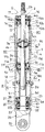
以下、図に示した実施の形態に基づき、本発明を説明する。図1に示すように、一実施の形態における緩衝器Dは、シリンダ1と、シリンダ1内に移動自在に挿入されるロッド2と、ロッド2の中間部に設けられるとともにシリンダ1内に摺動自在に挿入されて二つの圧力室R1,R2を隔成するピストン3と、シリンダ1を覆ってシリンダ1との間にエア抜き通路6を形成する外筒4と、シリンダ1の下端1b側から突出するロッド2の下端2aと外筒4との間に配置され外筒4との間にリザーバRを形成する内筒5と、内筒5の外周および外筒4の内周に摺接するとともに上記リザーバR内を気室Gと液室Lとに区画する環状のフリーピストン7と、シリンダ1の上端1aと外筒4の上端4aのそれぞれに嵌合されてロッド2の上端2b側を軸支する上方ロッドガイド10と、シリンダ1の下端1bと内筒5の上端5aのそれぞれに嵌合されてロッド2の下端2a側を軸支する下方ロッドガイド11と、外筒下端からの抜け止めされた状態で外筒4の下端4bと内筒5の下端5bに嵌合してリザーバ下端を封止するとともに気室G内への気体封入口20aを有する環状のボトム部材20とを備えて構成されている。
The present invention will be described below based on the embodiments shown in the drawings. As shown in FIG. 1, a shock absorber D according to an embodiment is provided in a cylinder 1, a
以下、各部材について詳細に説明すると、シリンダ1は、上端1aには環状の上方ロッドガイド10が嵌合され、下端1bには環状の下方ロッドガイド11が嵌合され、シリンダ1内は、シリンダ1内に摺動自在に挿入されたピストン3によって二つの圧力室R1,R2が区画され、これら圧力室R1,R2内には作動油等の液体が充填されている。そして、シリンダ1は、外筒4内に挿入されており、外筒4との間の環状隙間でエア抜通路6を形成している。
Hereinafter, each member will be described in detail. The cylinder 1 has an upper end 1 a fitted with an annular
また、ピストン3は、環状とされてシリンダ1内に移動自在に挿通されたロッド2の中間に取付けられ、上記圧力室R1と圧力室R2とを連通するポート3a,3bを有している。
The
このピストン3の図1中上方には、ポート3aを開閉するリーフバルブVaが積層されてロッド2の中間部に取付けられ、ピストン3の図1中下方には、ポート3bを開閉するリーフバルブVbが積層されてロッド2の中間部に取付けられている。
A leaf valve Va that opens and closes the port 3a is stacked and attached to an intermediate portion of the
さらに、ロッド2における下端2aは、シリンダ1の図1中下端1bを閉塞する環状の下方ロッドガイド11の内側に固定される筒状のベアリング13に挿通されてシリンダ1外へ突出させてあり、ロッド2の上端2bは、シリンダ1の図1中上端を閉塞する環状の上方ロッドガイド10の内側に固定される筒状のベアリング12に挿通されてシリンダ1外へ突出させてある。すなわち、ロッド2における下端2a側は、下方ロッドガイド11によって軸支され、上端2b側は、上方ロッドガイド10によって軸支されている。
Further, the
なお、ロッド2の下端2aは、制振対象となる車体や車軸へ連結されることがなく、軸力が作用しないので、軽量化等の目的で中空とされてもよい。
Note that the
そして、シリンダ1の外方には、このシリンダ1を覆って、シリンダ1との間に環状のエア抜き通路6を形成する外筒4が設けられており、この外筒4は、この実施の形態の場合、アルミニウムによって作られていて軽量化が図られ、シリンダ1より長尺とされ、シリンダ1の下端1bより下方へ延長されて、ロッド2の下端2aがシリンダ1の下端1bから最大限突出しても、当該下端2aの外周をカバーできるようになっている。すなわち、ロッド2の下端2aのストローク範囲をカバーすることができるようになっている。
An outer cylinder 4 is provided outside the cylinder 1 so as to cover the cylinder 1 and form an annular
また、外筒4の図1中上端4aの内周には上方側に配置される上方ロッドガイド10が嵌合固定されている。また、外筒4の下端4bの内周径は、小径に設定されて小径部4cが形成されており、この小径部4cの上端に段部4dが形成されている。
Further, an
また、外筒4の上端4aに嵌合される上方ロッドガイド10の外周には、シールリング14が装着されていて、外筒4と上方ロッドガイド10との間がシールされている。さらに、上方ロッドガイド10の上方にシール部材15が積層され、シール部材15の上方には、スペーサ16が積層され、さらに、スペーサ16は、外筒4に螺着されるナット部材17によって上方ロッドガイド10へ締め付けられている。
Further, a
そして、上方ロッドガイド10は、下端にシリンダ1の上端1aに嵌合する嵌合部10aを備えるとともに外周に段部10bが形成されて外筒4の上端4a内に嵌合されていて、シリンダ1を外筒4に対して径方向に位置決めしている。また、上方ロッドガイド10は、これを軸方向に貫く貫通孔10cを備えている。
The
なお、シール部材15の内周には、ロッド2の上端2bの外周に摺接するリップ部15aが設けられており、このリップ部15aには、上方ロッドガイド10に設けた貫通孔10cを介して圧力室R1内の圧力が作用しており、当該圧力によってロッド2の上端2bの外周へ押付けられて、ロッド2の上端2bの外周を緊迫して密にシールしている。また、シール部材15の外周には、上方ロッドガイド10に密着する外周シール部15bが設けられており、上方ロッドガイド10とシール部材15との間が密にシールされている。
In addition, a
したがって、シール部材15は、ロッド2の上端2bと上方ロッドガイド10との間をシールし、シールリング14と協働して外筒4とロッド2との間を密封している。
Therefore, the
外筒4の下端4bの小径部4cに嵌合されるボトム部材20は、環状であって、軸線に沿って肉を貫いて形成される気体封入口20aと、外周上方側の外径を大径に設定して設けた段部20bとを備えている。このボトム部材20を外筒4の上端4a側から外筒4内へ挿入するとともに外筒4の下端4bの内周に嵌合すると、段部20bが外筒4の段部4dに衝合して、外筒4の下端4bからの抜けが阻止された状態で外筒4の下端4bの内周に嵌合される。なお、ボトム部材20の外周のうち大径な上方側には、シールリング21が装着されており、このシールリング21で外筒4とボトム部材20との間に密にシールされる。
The bottom member 20 fitted into the
また、気体封入口20aは、気室Gへの気体の給排を行うために設けられており、リザーバRの内圧の調節を行うことができるようになっており、気体封入口20aにプラグ22を螺着することで気室Gを栓して、リザーバRの内圧を維持できるようになっている。
The
さらに、外筒4の下端4bの外周には緩衝器Dを車両へ取付可能な取付部30を備えたキャップ29が螺子締結によって装着されるようになっており、気室Gの気圧の調整が必要な場合には、キャップ29を取外して簡単にプラグ22へアクセスすることができるようになっている。また、各種の車両に合わせ取付部の形状が異なるキャップを複数用意しておくことで、キャップ交換を行うことで各種車両へ緩衝器Dを搭載することができる。
Further, a
そして、ボトム部材20の内周には、内筒5の下端5bが嵌合されている。内筒5は、上端5aが拡径されており、当該拡径された上端5aは、外筒4の内周に嵌合される。また、内筒5のボトム部材20の内周に嵌合される下端5bと上端5aとの間の中間部5cは下端5bよりも大径に設定されており、中間部5cと下端5bの境に形成される段部5dがボトム部材20の上端内周に係合して下方側への移動が規制されている。このように、内筒5は、下端5bがボトム部材20により径方向へ位置決めされ、上端5aが外筒4によって径方向へ位置決めされる。また、ボトム部材20の内周には、内筒5の下端5bの外周に密着するシールリング23が装着されており、内筒5とボトム部材20との間は密にシールされる。
The
このように、内筒5が外筒4に収容されると、内筒5と外筒4との間の環状隙間でリザーバRが形成される。そして、この環状隙間内には、内筒5の外周と外筒4の内周の双方に摺接するフリーピストン7が上下方向移動自在に収容され、リザーバRは、フリーピストン7より下方の気体が封入される気室Gと上方の液体が充填される液室Lとに区画される。また、リザーバRにおける液室Lは、内筒5の上端5aの外周に設けた溝5eによって、エア抜き通路6に連通される。
As described above, when the
さらに、内筒5の上端5a内周には、ロッド2の下端2aと内筒5との間をシールするシール部材18が収容されるとともに、シール部材18の上方には、ロッド2の下端2a側を軸支する下方ロッドガイド11が嵌合されている。なお、シール部材18の内周には、ロッド2の下端2aの外周に摺接するリップ部18aが設けられており、このリップ部18aには、下方ロッドガイド11に設けた貫通孔11dを介して圧力室R2内の圧力が作用しており、当該圧力によってロッド2の下端2aの外周へ押付けられて、ロッド2の下端2aの外周を緊迫して密にシールしている。また、シール部材18の外周には、下方ロッドガイド11に密着する外周シール部18bが設けられており、下方ロッドガイド11とシール部材18との間が密にシールされている。
Further, a
下方ロッドガイド11は、外周の中間に設けられてシリンダ1の下端1b面に当接する大径部11aと、大径部11aより上方側であって外径が大径部11aより小径でシリンダ1の下端1bの内周に嵌合する嵌合部11bと、大径部11aより下方側であって外径が大径部11aより小径で内筒5の上端5aの内周に嵌合する内筒嵌合部11cと、嵌合部11bの上端から軸方向に沿って外筒嵌合部11cの下端へ通じる貫通孔11d、圧力室R2側の端部となる嵌合部11bの上端から開口して大径部11aの外周へ通じる通孔11eを備えて構成されている。なお、大径部11aの外径は、外筒4の内径よりも小径に設定されており、大径部11aでリザーバRとエア抜き通路6との連通を遮断しないようになっている。
The
そして、上記通孔11eの嵌合部11b側の出口端には、オリフィス9を備えたプラグ24が螺着されており、通孔11eを通過する液体の流れにオリフィス9で抵抗を与えるようになっている。つまり、液室Lは、オリフィス9を介して圧力室R2に連通され、また、当該液室Lは、上記した溝5eを介してエア抜き通路6にも連通されている。
A
したがって、液室Lは、オリフィス9を介して内部の圧力を各圧力室R1,R2の圧力に作用させており、この緩衝器Dにあっては、両ロッド型に構成されて、シリンダ1内でピストン3が移動しても各圧力室R1,R2内の全体の容積変化は無いので、基本的には、ピストン作動時の体積補償を行わず、温度変化による各圧力室R1,R2内の液体の体積変化について液室L内の気体の体積変化で吸収し体積補償する。
Therefore, the liquid chamber L causes the internal pressure to act on the pressures of the pressure chambers R1 and R2 via the orifice 9, and the shock absorber D is configured as a double rod type, and the inside of the cylinder 1 Therefore, even if the
また、大径部11aは、内筒5の上端5aの外周に設けた溝5eを閉塞しないように、上端5aの上端に面する下端外周をテーパ面として逃げ部11fを設けている。当該逃げ部11fは、内筒5の下端外周を円弧状に切除したような形状として形成してもよい。
Further, the
このように構成された緩衝器Dを実際に組み立てるには、外筒4の上端4aの開口から、ボトム部材20、フリーピストン7、内筒5、シール部材18、下方ロッドガイド11、シリンダ1、ピストン3が一体に連結されたロッド2、上方ロッドガイド10、シール部材15およびスペーサ16を順に外筒4内に挿入してから、外筒4の上端4aの内周にナット部材17を螺着する。すると、外筒4内で最下方に収容されるボトム部材20が外筒4によって抜け止めされているので、ナット部材17を外筒4に対して下方へ捩じ込んでいくと、フリーピストン7およびピストン3が一体化されたロッド2は軸方向へ移動可能とされるものの、ボトム部材20とナット部材17との間で、内筒5、シール部材18、下方ロッドガイド11、シリンダ1、上方ロッドガイド10、シール部材15およびスペーサ16の一連の構成部材が挟持されて外筒4に軸方向移動不能に固定される。
In order to actually assemble the shock absorber D configured as described above, the bottom member 20, the
したがって、緩衝器Dを組み立てるには、外筒4の上端4a側から、緩衝器Dの構成部材を挿入して固定することができ、また、分解に際しても、ナット部材17を外筒4から取り外すことで、緩衝器Dの上記構成部材を外筒4から取り外すことができる。
Therefore, in order to assemble the shock absorber D, the constituent members of the shock absorber D can be inserted and fixed from the upper end 4a side of the outer cylinder 4, and the
つまり、緩衝器Dの組立および分解は、外筒4の上端4a側から行うことができ、外筒4の両端の双方で組立分解作業を行う必要がなく、ナット部材17の取り付け取り外しにて組立と分解を行うことができるので、緩衝器Dの組立および分解が簡単となり、その作業時間をも短縮することができる。 That is, the shock absorber D can be assembled and disassembled from the upper end 4 a side of the outer cylinder 4, and it is not necessary to perform assembly / disassembly work at both ends of the outer cylinder 4. Since the shock absorber D can be easily assembled and disassembled, the working time can be shortened.
また、ナット部材17の外筒4への螺合によって、緩衝器Dの構成部品を組立ることができるので、組立に際してトルク管理が必要な部材はナット部材17のみとなって、この点でも、組立作業が容易となる。
Further, since the components of the shock absorber D can be assembled by screwing the
さらに、緩衝器Dの上記構成部材がそれぞれ外筒4によって径方向に調芯されるようになっているので、組み上げられた緩衝器Dの円滑な伸縮が保障される。 Furthermore, since the component members of the shock absorber D are aligned in the radial direction by the outer cylinder 4, smooth expansion and contraction of the assembled shock absorber D is ensured.
つづいて、上述のよう構成された緩衝器Dの動作について説明する。緩衝器Dは、ピストン3がシリンダ1に対して図1中上方向に移動して伸長作動すると、圧力室R1から圧力室R2へ上記ポート3bを介して移動する液体の流れにリーフバルブVbで抵抗を与えて減衰力を発生し、逆に、ピストン3がシリンダ1に対して図1中下方に移動して圧縮作動すると、圧力室R2から圧力室R1へ上記ポート3aを介して移動する液体の流れにリーフバルブVaで抵抗を与えて減衰力を発生するようになっている。
Next, the operation of the shock absorber D configured as described above will be described. When the
このように、構成される緩衝器Dによれば、シリンダ1内を加圧する気室Gがロッド2の下端2aの外周に配置される内筒5と外筒4との間に形成されるので、ロッド2に気室G内の圧力による推力が負荷されない。
Thus, according to the buffer D comprised, since the air chamber G which pressurizes the inside of the cylinder 1 is formed between the
したがって、この緩衝器Dによれば、ロッド2に気室G内の圧力が作用しないので、気室G内の圧力の設定に制限を受けることがなく、シリンダ1内を加圧する気室G内の圧力を自由に設定することができ、緩衝器Dの発生減衰力や応答性の設定の自由度が飛躍的に高まり、気室G内の圧力を車両における乗り心地にとって最適となるように設定することができ、車両における乗り心地を飛躍的に向上させることができる。
Therefore, according to this shock absorber D, the pressure in the air chamber G does not act on the
そして、この緩衝器Dを実際に組み立てる際には、上方ロッドガイド10、シール部材15、スペーサ16およびナット部材17のみを組みつけていない状態で、圧力室R1,R2内へシリンダ1の上端開口部から、液室L内へはエア抜き通路6から液体を注入する。
When the shock absorber D is actually assembled, the upper end opening of the cylinder 1 is opened into the pressure chambers R1 and R2 in a state where only the
その後、上方ロッドガイド10を内周側にロッド2の上端2bを挿入させつつ、シリンダ1および外筒4に嵌合し、その上からシール部材15およびスペーサ16を積層し、最後にナット部材17を外筒4の上端内周に螺合することで組立が完了する。
Thereafter, the
この液体注入時に、シリンダ1内を介してエア抜きしにくい液室L内や通孔11e内等に混入した気体は、エア抜き通路6を介して速やかに緩衝器D外に排出される。したがって、緩衝器Dの組立工程やメンテナンスにおけるエア抜き作業を軽減でき、この点でも作業時間も短縮することができる。なお、圧力室R2内の気体は、ロッドガイド10の貫通孔10cを介してシリンダ1外へ排出される。
At the time of this liquid injection, the gas mixed in the liquid chamber L, the through
また、溝5eは、鉛直方向から視認できるようにエア抜き通路6に接続されているので、液室L内の気体を速やかにエア抜き通路6へ排出させることができる。
Further, since the
そしてまた、緩衝器Dの組立が終了した後に、万が一、液室L内の液体中に気泡が発生することがあっても、エア抜き通路6へ誘導されて、エア抜き通路6の上方に気体が溜まるだけで、圧力室R1、R2内への気体の混入を防止することができる。
In addition, even if bubbles are generated in the liquid in the liquid chamber L after the assembly of the shock absorber D is finished, the air is guided to the
さらに、溝5eを閉塞しないように下方ロッドガイド11の大径部11aの下端外周に逃げ部11fを設けているので、外筒4の内径とシリンダ1の外径とに差を大きくせずとも、液室L内の気体を速やかにエア抜き通路6へ排出させることができる。換言すれば、シリンダ1の内径を確保しつつも緩衝器Dの外径を小径化することができ、緩衝器Dの減衰力不足を招くことなく小型化することができるのである。なお、逃げ部11fの形状をテーパ面状とすると、より一層気体の移動を妨げることなくエア抜き通路6へ誘導できるようになる。
Furthermore, since the
また、外筒4には、高頻度で摺動する部材が摺接していないので、外筒4をアルミニウムで形成することができ、緩衝器Dを軽量化することができる。 Moreover, since the member which slides frequently is not slidably contacted with the outer cylinder 4, the outer cylinder 4 can be formed with aluminum and the buffer D can be reduced in weight.
さらに、圧力室R1,R2を介してロッド2の外周をシールするシール部材15,18へ気室G内の圧力を作用させることができ、気室G内の圧力の設定によってロッド2とシール部材15,18との間の摩擦力をチューニングすることができ、特に、ロッド2とシール部材15,18との間の摩擦力を大きくするようにしておくことによって、緩衝器Dの発生する減衰力に摩擦力を重畳させて、ピストン3がシリンダ1に対して移動する際のピストン速度が低い場合における減衰力を高めて、車体のローリング、ピッチング、スクワット等の挙動をしっかりと抑制することができるようになる。
Furthermore, the pressure in the air chamber G can be applied to the
また、ロッド2の径を太くしなくてはならない状況となっても、シリンダ1の外周側に形成されてロッド2が出入りすることのないエア抜き通路6のボリュームをもリザーバRの一部として使用することができるので、ロッド2の径に影響を受けずに液室Lの容積を確保することができ、緩衝器Dの全長が長くなることが無く、車両への搭載性を悪化することがない。
Further, even when the diameter of the
さらに、外筒4を介して緩衝器Dを車両の車体や車軸へ連結することができるので、シリンダ1に横力や軸力が直接的に作用することを回避できるとともに、外筒4でロッド2の一端2aのストローク範囲をカバーすることで、ロッド2の外周の滑らかな摺動面を飛石や泥等から保護することができる。なお、ロッド2の保護の必要が無い場合には、外筒4でロッド2の一端2aのストローク範囲全体をカバーせずに、内筒5および外筒4の長さを気室Gと液室Lを形成できる程度の長さに設定するようにしてもよい。
Furthermore, since the shock absorber D can be connected to the vehicle body and axle of the vehicle via the outer cylinder 4, it is possible to avoid the lateral force and axial force acting directly on the cylinder 1, and the outer cylinder 4 can be connected to the rod. By covering the stroke range of the one
そして、さらに、この実施の形態の場合、外筒4の開口端がキャップ29によって閉塞されるので、ロッド2に飛石や泥等が直接干渉することを確実に防止でき、ロッド2の保護が確実となる。
Further, in the case of this embodiment, since the open end of the outer cylinder 4 is closed by the
さらに、内筒5内はキャップ29によって閉塞されて、緩衝器Dが伸縮する際に、ロッド2の一端2aが閉空間とされる内筒5内に出入りして、当該内筒5内の気圧が変動して、ロッド2に内筒5内の気圧が作用するようになっているが、内筒5内には気圧を加圧して封入することなく大気圧を基準として変動する程度であるから内筒5内の気圧は然程大きくなることがなく、緩衝器Dが発生する減衰力に与える影響は小さく特段の問題は無いが、内筒5内が密閉とされないようにキャップ29あるいは外筒4に内筒5内へ通じる通孔を設けて内筒5が気体バネとして作用しないようにして減衰力への影響を排除するようにしてもよい。
Furthermore, the inside of the
また、ナット部材17は、外筒4の上端4aの内周に螺合されているが、スペーサ16を押圧することができれば、外筒4の上端4aの外周に螺着されてもうよい。たとえば、外筒4の上端4aの外周に螺着される筒部と、筒部の上端から内方へ形成したフランジとでナット部材を構成し、フランジでスペーサ16を押圧するようにすればよい。また、スペーサ16とナット部材17とを一体化して一部品としても構わない。
The
以上で、本発明の実施の形態についての説明を終えるが、本発明の範囲は図示されまたは説明された詳細そのものには限定されないことは勿論である。 This is the end of the description of the embodiment of the present invention, but the scope of the present invention is of course not limited to the details shown or described.
本発明の緩衝器は、たとえば、車両の制振用途に利用することができる。 The shock absorber of the present invention can be used, for example, for vibration control of a vehicle.
1 シリンダ
1a シリンダの上端
1b シリンダの下端
2 ロッド
2a ロッドの下端
2b ロッドの上端
3 ピストン
3a,3b ピストンにおけるポート
4 外筒
4a 外筒の上端
4b 外筒の下端
4c 外筒の小径部
4d 外筒の段部
5 内筒
5a 内筒の上端
5b 内筒の下端
5c 内筒の中間部
5d 内筒の段部
5e 内筒の溝
6 エア抜き通路
7 フリーピストン
9 オリフィス
10 上方ロッドガイド
10a 上方ロッドガイドの嵌合部
10b 上方ロッドガイドの段部
10c 上方ロッドガイドの貫通孔
11 下方ロッドガイド
11a 下方ロッドガイドの大径部
11b 下方ロッドガイドの嵌合部
11c 下方ロッドガイドの内筒嵌合部
11d 下方ロッドガイドの貫通孔
11e 下方ロッドガイドの通孔
11f 下方ロッドガイドの逃げ部
12,13 ベアリング
14,21,23 シールリング
15,18 シール部材
15a,18a シール部材のリップ部
15b,18b シール部材の外周シール部
16 スペーサ
17 ナット部材
20 ボトム部材
20a 気体封入口
20b ボトム部材の段部
22,24 プラグ
29 キャップ
30 取付部
D 緩衝器
G 気室
L 液室
R リザーバ
R1,R2 圧力室
Va,Vb リーフバルブ
1 cylinder 1a cylinder upper end 1b cylinder
Claims (1)
Priority Applications (1)
| Application Number | Priority Date | Filing Date | Title |
|---|---|---|---|
| JP2010271119A JP5481360B2 (en) | 2010-12-06 | 2010-12-06 | Shock absorber |
Applications Claiming Priority (1)
| Application Number | Priority Date | Filing Date | Title |
|---|---|---|---|
| JP2010271119A JP5481360B2 (en) | 2010-12-06 | 2010-12-06 | Shock absorber |
Publications (2)
| Publication Number | Publication Date |
|---|---|
| JP2012122494A true JP2012122494A (en) | 2012-06-28 |
| JP5481360B2 JP5481360B2 (en) | 2014-04-23 |
Family
ID=46504155
Family Applications (1)
| Application Number | Title | Priority Date | Filing Date |
|---|---|---|---|
| JP2010271119A Active JP5481360B2 (en) | 2010-12-06 | 2010-12-06 | Shock absorber |
Country Status (1)
| Country | Link |
|---|---|
| JP (1) | JP5481360B2 (en) |
Cited By (4)
| Publication number | Priority date | Publication date | Assignee | Title |
|---|---|---|---|---|
| JP2016065625A (en) * | 2014-09-25 | 2016-04-28 | 株式会社ショーワ | Buffer |
| WO2017010199A1 (en) * | 2015-07-14 | 2017-01-19 | Kyb株式会社 | Mono-tube shock absorber |
| WO2017146085A1 (en) * | 2016-02-24 | 2017-08-31 | 日立オートモティブシステムズ株式会社 | Cylinder device |
| KR101795733B1 (en) * | 2016-05-25 | 2017-11-08 | 주식회사 한일정밀 | A free-lock damper |
-
2010
- 2010-12-06 JP JP2010271119A patent/JP5481360B2/en active Active
Cited By (5)
| Publication number | Priority date | Publication date | Assignee | Title |
|---|---|---|---|---|
| JP2016065625A (en) * | 2014-09-25 | 2016-04-28 | 株式会社ショーワ | Buffer |
| WO2017010199A1 (en) * | 2015-07-14 | 2017-01-19 | Kyb株式会社 | Mono-tube shock absorber |
| JP2017020617A (en) * | 2015-07-14 | 2017-01-26 | Kyb株式会社 | Single cylinder type shock absorber |
| WO2017146085A1 (en) * | 2016-02-24 | 2017-08-31 | 日立オートモティブシステムズ株式会社 | Cylinder device |
| KR101795733B1 (en) * | 2016-05-25 | 2017-11-08 | 주식회사 한일정밀 | A free-lock damper |
Also Published As
| Publication number | Publication date |
|---|---|
| JP5481360B2 (en) | 2014-04-23 |
Similar Documents
| Publication | Publication Date | Title |
|---|---|---|
| US20060054435A1 (en) | Hydraulic shock absorber | |
| JP5403755B2 (en) | Shock absorber | |
| JP5481360B2 (en) | Shock absorber | |
| EP3027932B1 (en) | Hydraulic suspension damper | |
| WO2017175784A1 (en) | Shock absorber | |
| JP4996957B2 (en) | Shock absorber and shock absorber assembly tool | |
| JP2010236577A (en) | Hydraulic shock absorber of vehicle | |
| JP5809536B2 (en) | Vehicle shock absorber | |
| JP4939505B2 (en) | Shock absorber | |
| JP2009108938A (en) | Hydraulic shock absorber | |
| EP3242053B1 (en) | Suspension apparatus | |
| JP2011231796A (en) | Hydraulic shock absorber | |
| JP5506525B2 (en) | Hydraulic shock absorber | |
| JP2009236196A (en) | Hydraulic shock absorber | |
| JP5469592B2 (en) | Shock absorber | |
| JP2021081025A (en) | Buffer | |
| JP2016194338A (en) | Hydraulic shock absorber | |
| JP6377931B2 (en) | Front fork | |
| KR20100119569A (en) | Damper | |
| JP4858982B2 (en) | Shock absorber | |
| JP2008240745A (en) | Hydraulic shock absorber | |
| WO2017010199A1 (en) | Mono-tube shock absorber | |
| JP6484088B2 (en) | Front fork | |
| JP5642606B2 (en) | Hydraulic shock absorber | |
| JP3402817B2 (en) | Hydraulic shock absorber |
Legal Events
| Date | Code | Title | Description |
|---|---|---|---|
| A621 | Written request for application examination |
Free format text: JAPANESE INTERMEDIATE CODE: A621 Effective date: 20130625 |
|
| A977 | Report on retrieval |
Free format text: JAPANESE INTERMEDIATE CODE: A971007 Effective date: 20140120 |
|
| TRDD | Decision of grant or rejection written | ||
| A01 | Written decision to grant a patent or to grant a registration (utility model) |
Free format text: JAPANESE INTERMEDIATE CODE: A01 Effective date: 20140128 |
|
| A61 | First payment of annual fees (during grant procedure) |
Free format text: JAPANESE INTERMEDIATE CODE: A61 Effective date: 20140217 |
|
| R151 | Written notification of patent or utility model registration |
Ref document number: 5481360 Country of ref document: JP Free format text: JAPANESE INTERMEDIATE CODE: R151 |
|
| S533 | Written request for registration of change of name |
Free format text: JAPANESE INTERMEDIATE CODE: R313533 |
|
| R350 | Written notification of registration of transfer |
Free format text: JAPANESE INTERMEDIATE CODE: R350 |
|
| S533 | Written request for registration of change of name |
Free format text: JAPANESE INTERMEDIATE CODE: R313533 |
|
| R350 | Written notification of registration of transfer |
Free format text: JAPANESE INTERMEDIATE CODE: R350 |