JP2012117657A - Disk brake device - Google Patents
Disk brake device Download PDFInfo
- Publication number
- JP2012117657A JP2012117657A JP2010270934A JP2010270934A JP2012117657A JP 2012117657 A JP2012117657 A JP 2012117657A JP 2010270934 A JP2010270934 A JP 2010270934A JP 2010270934 A JP2010270934 A JP 2010270934A JP 2012117657 A JP2012117657 A JP 2012117657A
- Authority
- JP
- Japan
- Prior art keywords
- rotor
- slide pin
- pad
- hole
- pressure plate
- Prior art date
- Legal status (The legal status is an assumption and is not a legal conclusion. Google has not performed a legal analysis and makes no representation as to the accuracy of the status listed.)
- Pending
Links
Images


Abstract
Description
本発明はディスクブレーキ装置に係り、特にブレーキパッドをピンスライドさせるフローティング型のディスクブレーキ装置に関する。 The present invention relates to a disc brake device, and more particularly to a floating type disc brake device for pin-sliding a brake pad.
ブレーキパッドをピンスライドさせるタイプのフローティング型ディスクブレーキとしては、特許文献1に開示されているものが知られている。特許文献1に開示されているディスクブレーキ装置は、図28に示すように、ブレーキパッド2を構成するプレッシャプレート2aにおけるロータ回入側と回出側とのそれぞれに設けたアーム部3に、スライドピン5a,5bに当接する二股部4が形成されたものである。このような構成とすることで、ブレーキパッド2はスライドピン5a,5bに支持された状態を保ちつつ、ロータの軸方向へのスライドを実現することができる。
As a floating disc brake of a type in which a brake pad is slid into a pin, one disclosed in
しかし、このような構成のディスクブレーキ装置1では、制動時に回出側のスライドピン5bのみにトルク(制動トルク)が作用し、強度不足を補うために、スライドピン5bの直径を大径化する必要があった。しかしこの場合、ディスクブレーキ装置1の大型化、重量化などの問題が生ずる。また、ブレーキパッド2とスライドピン5a,5bとの間には拘束手段が無いため、車両走行時にはスライドピン5a,5bとブレーキパッド2との間でラトル音が生ずることとなり、制動時にはクロンク音(カチン音)が生ずることとなる。
However, in the
このような問題に対し、回出側のスライドピンに負荷される制動トルクを回入側に配置されたスライドピンにも分散させる構成を採用したディスクブレーキ装置として、特許文献2に開示されているものがある。特許文献2に開示されているディスクブレーキ装置では、ブレーキパッドの取り付け部に、スライドピンを挿通させるための貫通孔を設けている。このような構成とすることで、回出側のスライドピンにはブレーキパッドから押し方向の制動トルクが作用し、回入側のスライドピンにはブレーキパッドから引き方向の制動トルクが作用することとなり、制動時に生ずる制動トルクの分散が図られる。
In order to solve such a problem,
特許文献2に開示されているような構成のディスクブレーキ装置であれば、スライドピンに負荷される制動トルクの分散を図ることができる。しかし特許文献2に開示されているディスクブレーキ装置でも、ブレーキパッドは拘束されていないため、ラトル音やクロンク音(カチン音)についての対策は不十分である。
With the disc brake device having a configuration as disclosed in
そこで本発明では、ブレーキパッドをピンスライドさせるフローティング型のディスクブレーキ装置であって、スライドピンに負荷される制動トルクを分散させると共に、ラトル音やクロンク音(カチン音)を抑制することのできるディスクブレーキ装置を提供することを目的とする。 Accordingly, in the present invention, a floating type disc brake device for pin-sliding a brake pad, which can disperse braking torque applied to the slide pin and suppress rattle noise and clunk noise (click sound). An object is to provide a brake device.
上記目的を達成するための本発明に係るディスクブレーキ装置は、キャリパの爪部内壁面に対してアウタパッドのプレッシャプレートを凹凸嵌合させて成るフローティング型のディスクブレーキ装置であって、前記プレッシャプレートは、ロータの回入側と回出側に一対、車両に固定されるサポートから延設されるスライドピンを挿通させるための貫通孔と、前記スライドピンを基点として前記プレッシャプレートを係止するパッドクリップを備え、一対の前記貫通孔間の中心ピッチP1と前記スライドピン間の中心ピッチP2との関係が、P1>P2であり、前記パッドクリップは、前記爪部の内壁面に設けた凹部に嵌合された前記アウタパッドを前記爪部に付勢させる第1バネ部と、前記プレッシャプレートを前記スライドピンに付勢させ、一対の前記貫通孔のうち、ロータ回入側に設けられた貫通孔ではロータ半径方向外側のロータ回出側に位置する内周面に、ロータ回出側に設けられた貫通孔ではロータ半径方向外側のロータ回入側に位置する内周面に、それぞれ前記スライドピンを当接させる第2バネ部からなることを特徴とする。 In order to achieve the above object, a disc brake device according to the present invention is a floating type disc brake device in which a pressure plate of an outer pad is engaged with an inner wall surface of a claw portion of a caliper, and the pressure plate includes: A pair of rotor inlet and outlet sides, a through hole for inserting a slide pin extending from a support fixed to the vehicle, and a pad clip for locking the pressure plate with the slide pin as a base point provided, the relationship between the central pitch P 2 between the centering pitch P 1 between a pair of the through-hole slide pin, a P 1> P 2, wherein the pad clip is provided on the inner wall surface of the pawl portion A first spring portion for urging the outer pad fitted in the recess to the claw portion and the pressure plate is attached to the slide pin. Of the pair of through-holes, the through-hole provided on the rotor feed-in side has an inner circumferential surface located on the rotor feed-out side outside the rotor in the radial direction, and the through-hole provided on the rotor feed-out side It is characterized by comprising second spring portions each abutting the slide pin on the inner peripheral surface located on the radially outer rotor entrance side.
また、上記目的を達成するための本発明に係るディスクブレーキ装置としては、キャリパの爪部内壁面に対してアウタパッドのプレッシャプレートを凹凸嵌合させて成るフローティング型のディスクブレーキ装置であって、前記プレッシャプレートは、ロータの回入側と回出側に一対、車両に固定されるサポートから延設されるスライドピンを挿通させるための貫通孔と、前記スライドピンを基点として前記プレッシャプレートを係止するパッドクリップを備え、一対の前記貫通孔間の中心ピッチP1と前記スライドピン間の中心ピッチP2との関係が、P1<P2であり、前記パッドクリップは、前記爪部の内壁面に設けた凹部に嵌合された前記アウタパッドを前記爪部に付勢させる第1バネ部と、前記プレッシャプレートを前記スライドピンに付勢させ、一対の前記貫通孔のうち、ロータ回入側に設けられた貫通孔ではロータ半径方向内側のロータ回入側に位置する内周面に、ロータ回出側に設けられた貫通孔ではロータ半径方向内側のロータ回出側に位置する内周面に、それぞれ前記スライドピンを当接させる第2バネ部からなることを特徴とするものであっても良い。
この場合において、前記パッドクリップは、前記プレッシャプレートに固定される基部と、前記第1及び第2バネ部を一体的に形成するとよい。
In order to achieve the above object, the disc brake device according to the present invention is a floating type disc brake device in which a pressure plate of an outer pad is engaged with an inner wall surface of a claw portion of a caliper. The plate engages the pressure plate with a slide hole extending from a support fixed to the vehicle as a pair on the turn-in side and the turn-out side of the rotor, and the slide pin as a base point. comprising a pad clip, the relationship between the central pitch P 2 between centers pitches P 1 and the slide pin between a pair of the through hole is a
In this case, the pad clip may be formed integrally with a base portion fixed to the pressure plate and the first and second spring portions.
上記のような特徴を有するディスクブレーキ装置によれば、スライドピンに負荷される制動トルクを分散させると共に、ラトル音やクロンク音(カチン音)を抑制することが可能となる。
またスライドピンに安定接触するアウタパッドを介してキャリパボディを安定させることができる。よって、アウタパッドがロータ側へ倒れ込むことを防止することができ、アウタパッドの偏摩耗を抑制することができる。
According to the disc brake device having the above-described characteristics, it is possible to disperse the braking torque applied to the slide pin and to suppress the rattle noise and the clunk sound (click sound).
Further, the caliper body can be stabilized through the outer pad that is in stable contact with the slide pin. Therefore, the outer pad can be prevented from falling to the rotor side, and uneven wear of the outer pad can be suppressed.
またパッドクリップの構成を簡易かつ小型なものとすることができる。また、展開状態での平面形態をシンプルなものとすることで、板取性が良好となり、第1及び第2バネ部を折り曲げ加工して一体的に形成することにより、部品点数を減らして、製造コストを安価とすることができる。
また基部からバネ部の作用点までの距離を長くすることにより、荷重ばらつきを抑制することができる。
Further, the configuration of the pad clip can be made simple and small. In addition, by simplifying the planar form in the unfolded state, the plate cutting property is improved, and the first and second spring parts are bent and formed integrally, thereby reducing the number of parts and manufacturing. Cost can be reduced.
Further, by increasing the distance from the base portion to the action point of the spring portion, it is possible to suppress load variation.
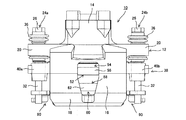
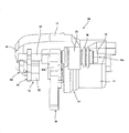
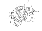
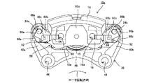
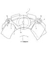
以下、本発明のディスクブレーキ装置に係る実施の形態について、図面を参照しつつ詳細に説明する。なお、図1は第1の実施形態に係るディスクブレーキ装置に係る平面図であり、図2は正面図であり、図3は右側面図である。また、図4は第1の実施形態に係るディスクブレーキ装置の右下面側斜視図である。 Hereinafter, embodiments of the disc brake device according to the present invention will be described in detail with reference to the drawings. FIG. 1 is a plan view of the disc brake device according to the first embodiment, FIG. 2 is a front view, and FIG. 3 is a right side view. FIG. 4 is a right lower surface side perspective view of the disc brake device according to the first embodiment.
本実施形態に係るディスクブレーキ装置10は、サポート38と、このサポート38に係合するスライドピン24(24a,24b)、およびスライドピン24に係合するキャリパ12、並びにブレーキパッド(インナパッド52,アウタパッド58)を基本として構成される。
The
サポート38は、ディスクブレーキ装置10を車両に固定すると共に、車輪と共に回転するロータ(不図示)の制動トルクを受け止めるトルク受けとしての役割を担う。サポート38は、詳細を後述するスライドピン24を係合させるために設けられる一対のトルク受け部40(40a,40b)と、一対のトルク受け部40を連結するサポートブリッジ部46とを有し、全体形状として略コ字状を成す。
The
トルク受け部40の先端側にはそれぞれ、スライドピン24を係合させるためのネジ孔42(図5参照)が設けられている。トルク受け部40とサポートブリッジ部46との接合箇所には、サポート38を車両等に固定するための取付孔44が設けられている。また、一対のトルク受け部40の対向する側面には、対向位置に、略コ字状の凹部48が形成されている。凹部48は、詳細を後述するインナパッド52(ブレーキパッド)を保持すると共に摺動させるための摺動レールとしての役割を担う。
A screw hole 42 (see FIG. 5) for engaging the slide pin 24 is provided on the distal end side of the torque receiving portion 40. An
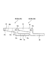
スライドピン24は、上述したサポート38のトルク受け部40に設けられたネジ孔42に螺合され、詳細を後述するキャリパ12とアウタパッド58(ブレーキパッド)の摺動レールとしての役割を担うと共に、制動時には、アウタパッド58のトルク受けとしての役割も担う。
The slide pin 24 is screwed into a
スライドピンは図5に示すように、サポート38との螺合部30を基点として、先端側にアウタパッド58の摺動部を有し、基端側にキャリパ12の摺動部を有することとなる。このため、スライドピン24は、締付けのためのボルト頭26とキャリパ摺動部28、螺合部30、およびアウタパッド摺動部32を有することとなる。本実施形態に係るキャリパ12は詳細を後述するように、アーム部20に設けられた貫通孔22を介してスライドピン24に係合し、また、貫通孔22とスライドピン24との間には、スリーブ34とブーツ36が設けられる。スリーブ34は、キャリパ12のスライド量を確保する。一方ブーツ36は、スリーブ34と貫通孔22との間の摺動部にダストが付着することを防止すると共に、スリーブ34と貫通孔22とのダンピング機能を有する。
As shown in FIG. 5, the slide pin has a sliding portion of the
キャリパ12は、キャリパ本体14と爪部18、キャリパブリッジ部16、およびアーム部20を基本として構成される。キャリパ本体14には、図示しないロータのインナ側に配置され、少なくともシリンダ(不図示)と、ピストン15が設けられる。シリンダ内には、ブレーキ操作により作動油が流入し、流入した作動油を介してピストン15が押し出され、詳細を後述するインナパッド52におけるプレッシャプレート54を押圧することとなる。シリンダの開口部とピストン15の先端部の間には、蛇腹状のピストンブーツ(不図示)が設けられ、摺動部へのダストの付着防止が図られている。
The
爪部18は、ロータを介してキャリパ本体14と反対側、すなわちロータのアウタ側に配置され、詳細を後述するアウタパッド58を支持する役割を担う。爪部18は、詳細を後述するキャリパブリッジ部16を基点として、ロータ半径方向内側へ向けて延設されている。このため、爪部18とキャリパ本体14とはロータを介して対向する位置に設けられる。また、本実施形態に係るディスクブレーキ装置10では、爪部18におけるロータの回入側と回出側の双方に貫通孔18a,18aが設けられ、詳細を後述するアウタパッド58の凸部を爪部18の内壁に凹凸嵌合可能な構成としている。なお貫通孔18a,18bにかえて有底の袋穴としてもよい。
The
アーム部20は、キャリパ本体14から両端側(ロータの回入側と回出側)へ延設された係合部である。アーム部20の先端側には、スライドピン24におけるキャリパ摺動部28に係合するための貫通孔22(図5参照)が設けられており、この貫通孔22を介してスライドピン24との係合が成される。
The
本実施形態に係るディスクブレーキ装置10ではブレーキパッドとして、サポート38に設けられた凹部48を摺動するインナパッド52と、スライドピン24a,24bを摺動するアウタパッド58とを備える。なお、インナパッド52、アウタパッド58共に、プレッシャプレート54,60と、プレッシャプレート54,60に添着された摩擦部材であるライニング56,62とを基本として構成される。
The
インナパッド52におけるプレッシャプレート54は、ライニング56よりも一回り大きな金属の平板により略扇状に形成されたプレート本体と、このプレート本体の両端に突設された耳部(不図示)を有する。プレッシャプレート54の耳部をサポート38に形成された凹部48に遊嵌させることで、インナパッド52がロータの軸方向へスライド可能となる。なお、サポート38の凹部48には、金属板により構成されたパッドクリップ50が設けられ、インナパッド52がロータ軸方向へ摺動する際の摺動抵抗の低減と走行時の引き摺り防止が図られている。
The
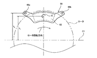
アウタパッド58におけるプレッシャプレート60は図6に示すように、ライニング62よりも一回り大きな金属の平板により略扇状に形成されたプレート本体60aと、このプレート本体60aの両端に、プレート本体60aを基点として略V字状となるように突設されたアーム部60bおよびアーム部60bの先端側に形成された貫通孔66(66a,66b)を有する。貫通孔66はスライドピン24よりも径大に形成されている。アウタパッド58は、アーム部60bの貫通孔66にスライドピン24におけるアウタパッド摺動部32を挿通させることで、スライドピン24上での摺動が可能となる。また、アウタパッド58におけるプレッシャプレート60のライニング添着面と反対側の爪部18との当接面には、キャリパ12の爪部18に設けた貫通孔18aに対応する位置に、一対の第1凸部64が形成されている。一対の第1凸部64を爪部18の貫通孔18a(凹部)に嵌合させることで、キャリパ12をアウタパッド58に対して安定保持させることが可能となる。
As shown in FIG. 6, the
また、本実施形態に係るアウタパッド58は、プレート本体60aとアーム部60bの間に一対の第2凸部60cが設けられている。第2凸部60cには後述するパッドクリップ90が固定される。
Further, the
また、本実施形態に係るディスクブレーキ装置10では、アウタパッド58における貫通孔66a,66bの中心ピッチP1と、スライドピン24a,24bの中心ピッチP2とが
P1>P2
の関係を満たすように、貫通孔66a,66bのピッチP1が定められている。このような構成とした場合図7に示すように、制動初期時等の低制動トルク発生時には回出側に配置されたスライドピン24bのみに貫通孔66bの内壁が接触し、スライドピン24bのみに制動トルクが負荷されることとなる。一方、高い制動トルクが生じた場合には、回出側に配置されたスライドピン24bが制動トルク負荷方向に撓み、回入側に配置されたスライドピン24aに貫通孔66aの内壁が接触することとなり、一対のスライドピン24a,24bに制動トルクが分散されることとなる。このように、制動トルクの高低に応じて制動トルクを分散させることを可能にすることで、スライドピン24の大径化等、強度補強を行う必要性がなくなり、スライドピンの大径化に伴う重量増加等を抑制することができる。
Further, in the
So as to satisfy the relationship, the through-
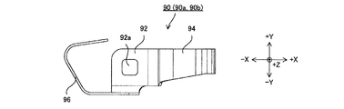
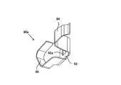
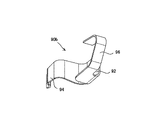
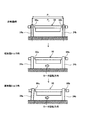
本実施形態に係るパッドクリップ90は、図8〜図13に詳細を示すように、基部92と第1バネ部94、および第2バネ部96を基本として構成されている。なお、図面において、図8はパッドクリップの平面図、図9は正面図、図10は右側面図である。また、図11、および図12は一対のパッドクリップ90a,90bの双方を示す斜視図であり、図13はパッドクリップの展開平面図である。
As shown in detail in FIGS. 8 to 13, the
パッドクリップ90は、図13に示すように、基部92に連接された第1支持片93と第2支持片95からなる板状部材を折り曲げ形成することで構成される。第1バネ部94と第2バネ部96とは、バネとして作用する面が直交する関係となるため、折り曲げ加工前の展開状態では、その平面形状は、略S字状、あるいはクランク状の部材となる。なおパッドクリップ90の材質はステンレス鋼などを用いることができる。
As shown in FIG. 13, the
基部92は、板状部材の中心付近に固定孔92aを備えている。パッドクリップ90は、基部92に設けた固定孔92aを介して、プレッシャプレート60のアーム部60bに定められた第2凸部60c(図2参照)に固定される。なお、パッドクリップ90の固定は、凹凸を利用したカシメ加工や他のクリップ等を用いた挟持、およびネジ止めなどにより行うことができる。
The
パッドクリップ90を構成する第1バネ部94は、第1支持片93を折り曲げて形成することができる。具体的には、第1支持片93における第1折り曲げ部93aを基部92に対して略直交する方向に谷折りし、ついで第2折り曲げ部93bを山折りする。クランク状を成し、基部92に対して略平行となった第1支持片93の先端に位置する第3折り曲げ部93cを波状に折り曲げて接触部を形成する。これにより、第1バネ部94は、キャリパ12の爪部18に係止可能となる。
The
第2バネ部96は、第2支持片95を折り曲げて形成することができる。具体的には、第2支持片95における第1折り曲げ部95aを基部92に対して略直交する方向に谷折りする。第2支持片95に設けられた第2折り曲げ部95b、第3折り曲げ部95cを共に谷折りする。
The
このように構成される本実施形態のパッドクリップ90は、ロータの回入側と回出側に一対配置されることとなるが、図2や図11、図12に示すようにロータの回入側と回出側とで、左右対称な形態となるように構成される。このような形態を構成するには、展開形状からの第1折り曲げ部93a,95aの折り曲げ方向の基準面を異ならせることで可能となる。このような構成のパッドクリップ90は、図13に示すような形態で配置することで、板取性を向上させることができ、端材に相当する面積を少なくすることによって製造コストの削減を図ることができる。
The
パッドクリップ90の取り付けは上述したように、アウタパッド58におけるプレッシャプレート60のアーム部60bに設けられた第2凸部60cにパッドクリップ90の基部92を固定することで成される。そして、第1バネ部94の先端部分を爪部18に係止し、スライドピン24の先端をアウタパッド58の貫通孔66に挿入し、第2バネ部96をスライドピン24のアウタパッド摺動部32に付勢させることで、キャリパ12に対するアウタパッド58の組付けを成す。本実施形態では図2に示すように、ロータ回入側に設けたパッドクリップ90aの第2バネ部96の先は、スライドピン24aを基準としてロータ半径方向内側であってロータ回出側に付勢させ、ロータ回出側に設けたパッドクリップ90bの第2バネ部96の先端は、スライドピン24bを基準としてロータ半径方向内側であってロータ回入側に付勢させている。このような組付け状態とすることで、アウタパッド58はスライドピン24を基点(アース)としてロータ半径方向内側に押下げられる力を受ける。
As described above, the
また上記パッドクリップ90を設けたアウタパッド58では、アウタパッド58を爪部18へ固定する際、プレッシャプレート60に設けた凸部64を貫通孔18aへ嵌合させると共に、第1バネ部94により爪部18を挟み込むことで、アウタパッド58を爪部18へ付勢させる。これにより、アウタパッド58の倒れ込みを防ぎ、ライニングの偏摩耗を防止することができる。また、アウタパッド58は、一対のパッドクリップ90により、スライドピン24に対して安定接触することとなる。このため、スライドピン24を介して安定保持されるアウタパッド58に対して爪部18を付勢させることで、キャリパ12のガタツキを防止し、安定させることができる。なお、パッドクリップ90は基部92から第1バネ部94の作用点である先端までの距離を長くすることにより、荷重のバラツキを抑制することができる。
Further, in the
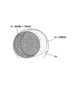
また、本実施形態では、アウタパッド58における貫通孔66の形態を次のようなものとしている。すなわち、スライドピン24を押し付ける側の壁面の平面形態を円弧状とし、押し付け側と反対側の壁面を平坦とし、いわゆる円弧と弦を組み合わせた形態としている。なお、本実施形態の場合、円を弦によって分けられる2つの円弧のうち、弧状部が長い方、すなわち優弧と弦を組み合わせた馬蹄形の貫通孔66を構成している。本実施形態に係るディスクブレーキ装置10では、パッドクリップ90によりアウタパッド58をスライドピン24に押し付ける形態を採っている。このため、スライドピン24を押し付けた側と反対側に位置する貫通孔66の壁面とスライドピン24との間には大きな隙間が生ずることとなる。そして、スライドピン24と貫通孔66の壁面との間に必要以上の隙間を設けた場合、スライドピン24と貫通孔66との間でのラトル音が増大する要因となる。よって、その隙間を埋めるように貫通孔66の一部を狭めることで、無用なガタツキを防止し、ラトル音の抑制を成すことができる。
In the present embodiment, the form of the through hole 66 in the
このような構成を有するディスクブレーキ装置10によれば、爪部18に嵌着されたアウタパッド58をスライドピン24に対してメタルタッチで支持することとなる。このため、スライドピン24に対してスリーブ34およびブーツ36を介して係止されたキャリパ12の倒れ込みを防止し、ガタツキを抑えることができる。
According to the
次に、このような構成を有するディスクブレーキ装置10における制動時の動作について説明する。まず、車両運転者が図示しないブレーキペダルやブレーキレバーを操作すると、キャリパ本体14のシリンダに作動油が充填される。シリンダへの作動油の充填に伴い、シリンダ内に収容されているピストン15がロータ側へ押し出される。シリンダから押し出されたピストン15は、サポート38のトルク受け部40に支持されたインナパッド52のプレッシャプレート54を押圧し、インナパッド52におけるライニング56をロータの摺動面に押し付ける。インナパッド52のライニング56がロータに押し付けられると、キャリパ本体14は押し付け力の反力を受け、スライドピン24に沿ってロータから離間するようにスライドする。キャリパ本体14がロータから離間するようにスライドすると、キャリパブリッジ部16によりキャリパ本体14に連接されている爪部18は、ロータ側に引き寄せられるように動作する。爪部18がロータ側に引き寄せられると、爪部18に固定されたアウタパッド58のプレッシャプレートが爪部18により押圧され、スライドピン24に沿ってロータ側へスライドし、ライニング62がロータ摺動面に押し付けられる。
Next, the operation at the time of braking in the
上記動作によりインナパッド52とアウタパッド58によりロータ摺動面が挟持されると、摩擦力によりインナパッド52とアウタパッド58は、ロータ回出方向へ連れ回りする力を受ける。この時、インナパッド52はプレッシャプレート54における耳部がサポート38のトルク受け部40に形成された凹部48に当接し、制動時に生ずる制動トルクを受けることで制動力を生じさせる。一方アウタパッド58は、図7に示すように回出側のスライドピン24bと回入側のスライドピン24aの双方により制動トルクを受け、これを車両本体に固定されたサポート38に伝達することで、制動力を生じさせる。なお、上述したように、アウタパッド58における制動トルクは、回出側のスライドピン24bと回入側のスライドピン24aに分散し、入力される。
When the rotor sliding surface is sandwiched between the
また、本実施形態に係るディスクブレーキ装置10では、スライドピン24に対して貫通孔66の半径方向外側に位置する内周面が押し付けられた状態を維持しているため、アウタパッド58が制動トルクを受けた際、引き側(回入側)では、図15に示すように、貫通孔66aにおける円弧状の内周面に沿って(点線、および破線で示した軌跡に沿って)スライドピン24aが移動するようにプレッシャプレート60がずれることとなる。このため、高制動トルク負荷時にスライドピン24aが急激に反対側の壁面に衝突するという事態が生じず、押しアンカから押し+引きアンカへの切り替わりが急激に行われずに、徐々に行われるため、接触変化の安定化を図ることができる。その結果、制動時のクロンク音(カチン音)が抑制される。また、本実施形態に係るディスクブレーキ装置10では、インナパッド52のみをサポート38で保持する形態としたため、サポート38がロータを跨ぐ構成とする必要が無い。このため、アウタ側の凹部形成等のためのサポート38の切削加工時間を短縮することができると共に軽量化が図れる。
Further, in the
上記のような構成を持ち、上記のようにして動作するディスクブレーキ装置10は、以下のように組付けることにより構成される。まず、サポート38にインナパッド52を配置すると共に、キャリパ12の爪部18にアウタパッド58を嵌着する。その後、キャリパ12を所定位置に保持した状態で、スライドピン24を取り付ける。スライドピン24は、螺合部30を基点として先端側にアウタパッド58の貫通孔66を、基端側にキャリパ12の貫通孔22を挿通する。
The
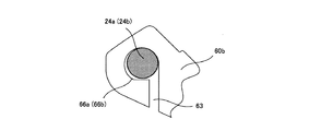
なお、上記実施形態では、貫通孔66の平面形態について、優弧と弦を組み合わせて成る馬蹄形として説明したが、その機能としては、制動トルクをスライドピン24a,24bに分配することができる形態であれば良い。よって、本願における貫通孔66には、図16に示すようなスリット63を有するものも含まれる。すなわち、スライドピン24の付勢、および制動トルク負荷時のスライドピン24の押し付けに係わらない壁面であれば、貫通孔66の内壁面が一部欠落していても、貫通孔とみなすことができる。
In the above embodiment, the planar shape of the through hole 66 has been described as a horseshoe shape formed by combining a dominant arc and a string. However, as a function thereof, the braking torque can be distributed to the slide pins 24a and 24b. I just need it. Therefore, the through-hole 66 in the present application includes one having a
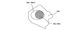
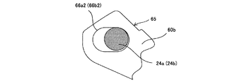
また、図14に示す例では、貫通孔は優弧と弦により構成されるものとして説明しているが、本願における貫通孔は、図17に示すような楕円形状の貫通孔66a1(66b1)や、図18に示すような長円形状の貫通孔66a2(66b2)としても良い。貫通孔の形態をこのようなものとした場合であっても、制動トルクの分配やクロンク音(カチン音)の抑制、およびラトル音の抑制といった効果を奏することができるからである。 Further, in the example shown in FIG. 14, the through hole is described as being constituted by a dominant arc and a string. However, the through hole in the present application is an elliptical through hole 66a1 (66b1) as shown in FIG. Further, an oval through hole 66a2 (66b2) as shown in FIG. 18 may be used. This is because even if the shape of the through hole is such, effects such as distribution of braking torque, suppression of cronk sound (click sound), and suppression of rattle sound can be achieved.
また、上記貫通孔はいずれも、円形を主体として構成されるものであるが、本実施形態に係る貫通孔は、図19に示すように円形と方形(矩形)の組み合わせにより構成するものであっても良い。具体的には、スライドピン24の押し付けを受ける辺(ロータ半径方向外側)を円弧(半円)により構成し、押し付けを受けない辺(ロータ半径方向内側)を方形により構成するというものである。このような構成とした場合、スライドピン24のロータ半径方向内側におけるロータ回入側と回出側に位置する貫通孔66a3,66b3との間の隙間を広げることができる。よって、円形の孔を弦により分割し、その優弧側部分を貫通孔とする場合(例えば図14に示す例の場合)と同様に、スライドピン24と貫通孔66とのガタツキによるラトル音を抑制する効果を奏することに加え、その余の隙間を広げることができる。これにより、スライドピン24と貫通孔66a3,66b3との間に水が溜まったとしても、この水の抜け性を良好にすることができ、該当部分に生ずる錆を抑制することができる。なお、貫通孔66a3,66b3における方形部分の角部にRを設けることで、制動トルク負荷時における応力集中による割れを抑制することができる。 Further, each of the through holes is mainly composed of a circle, but the through hole according to the present embodiment is composed of a combination of a circle and a rectangle (rectangle) as shown in FIG. May be. Specifically, the side that receives the pressing of the slide pin 24 (the outer side in the rotor radial direction) is configured by an arc (semicircle), and the side that does not receive the pressing (the inner side in the rotor radial direction) is configured by a square. With such a configuration, it is possible to widen the gap between the through holes 66a3 and 66b3 located on the rotor turn-in side and the turn-out side on the inner side in the rotor radial direction of the slide pin 24. Therefore, as in the case where the circular hole is divided by the strings and the dominant arc side portion is formed as a through hole (for example, in the case of the example shown in FIG. 14), rattle noise caused by rattling between the slide pin 24 and the through hole 66 is generated. In addition to exerting the suppressing effect, the remaining gap can be widened. Thereby, even if water accumulates between the slide pin 24 and the through-holes 66a3 and 66b3, the water can be easily removed and rust generated in the corresponding portion can be suppressed. In addition, the crack by the stress concentration at the time of braking torque load can be suppressed by providing R at the corner | angular part of the square part in through-hole 66a3, 66b3.
上記実施形態においては、貫通孔66を構成する優弧の直径をφD、スライドピン24の直径をφdとした場合(図14参照)、φDとφdの差となるΔdが、スライドピン24(上記実施形態の場合スライドピン24b)が弾性変形することにより得られるアウタパッド58のシフト距離よりも短くなるように定める。このような構成とすることで、スライドピン24が弾性変形する範囲で制動トルクの分散が図られることとなる。
In the above embodiment, when the diameter of the dominant arc constituting the through hole 66 is φD and the diameter of the slide pin 24 is φd (see FIG. 14), Δd that is the difference between φD and φd is the slide pin 24 (above In the case of the embodiment, the
上記実施形態に係るディスクブレーキ装置10では図20に示すように、制動時にアウタパッド58に生ずる偶力(モーメント)が矢印Aに示す方向に働いている場合を前提として説明した。このような方向にモーメントを生じさせるための手段の一例としては、ロータ中心軸C1からアウタパッド58のモーメント中心までの距離t1よりも、ロータ中心軸C1から貫通孔66の中心までの距離t2が長い場合の構成を挙げることができ、上記実施形態に係るディスクブレーキ装置10の構成もこれに準じている。
The
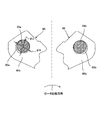
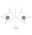
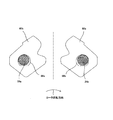
一方、制動時にアウタパッド58に生ずる偶力(モーメント)が矢印A′に示すように逆向きとなった場合(図21参照)、スライドピン24に対するアウタパッド58の押し付け方向が逆向きとなるようにパッドクリップが装着される(パッドクリップは不図示)。この場合におけるスライドピン24と貫通孔66との関係は、図22に示すようなものとなる。具体的には、ロータの回入側に配置されたパッドクリップ90a(図11参照)は、スライドピン24aに対して、第2バネ部96をロータ半径方向内側のロータ回出側へ向けて当接させる。これにより、アウタパッド58はスライドピン24aに対して、ロータ半径方向外側のロータ回入側へ向けて押し付けられる力を受ける。その結果、貫通孔66aではロータ半径方向内側のロータ回出側に位置する内周面がスライドピン24aに付勢する。一方、ロータの回出側に配置されたパッドクリップ90bは、スライドピン24bに対して、第2バネ部96をロータ半径方向内側のロータ回入側へ向けて当接させる。これにより、アウタパッド58はスライドピン24bに対して、ロータ半径方向外側のロータ回出側へ向けて押し付けられる力を受ける。その結果、貫通孔66bではロータ半径方向内側のロータ回入側に位置する内周面がスライドピン24bに付勢する。
On the other hand, when the couple (moment) generated in the
このような構成とする場合には、貫通孔66における優弧と弦との関係は、相対的に、優弧がロータ半径方向内側、弦が半径方向外側に位置することとなる。なお、このような方向にモーメントを生じさせるための手段の一例としては、図20に示すように、ロータ中心軸C1からアウタパッド58のモーメント中心までの距離t1が、ロータ中心軸C1から貫通孔66の中心までの距離t2よりも長い場合の構成を挙げることができる。
In the case of such a configuration, the relationship between the dominant arc and the chord in the through-hole 66 is such that the dominant arc is located on the inner side in the rotor radial direction and the chord is located on the outer side in the radial direction. As an example of means for producing a moment in this direction, as shown in FIG. 20, the distance t 1 from the rotor center axis C 1 to moment center of the
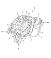
次に、本発明のディスクブレーキ装置に係る第2の実施形態について、以下説明する。図23は第2の実施形態に係るディスクブレーキ装置の右下面側斜視図である。図24は第2の実施形態に係るディスクブレーキ装置の正面形態を示す図である。 Next, a second embodiment according to the disc brake device of the present invention will be described below. FIG. 23 is a perspective view of the lower right side of the disc brake device according to the second embodiment. FIG. 24 is a diagram showing a front view of the disc brake device according to the second embodiment.
なお、本実施形態に係るディスクブレーキ装置10aの殆どの構成は、上述した第1の実施形態に係るディスクブレーキ装置10と同様である。よって、その構成を同一とする箇所には図面に同一符号を附して詳細な説明は省略することとする。
Note that most of the configuration of the
本実施形態に係るディスクブレーキ装置10aは、第1の実施形態に係るディスクブレーキ装置10と異なり、アウタパッド58における貫通孔66a,66b間の中心ピッチP1とスライドピン24a,24b間の中心ピッチP2との関係が、
P1<P2
の関係を満たすように、貫通孔66a,66bのピッチP1が定められている。このような構成とした場合図25に示すように、低制動トルク負荷時には回入側に配置されたスライドピン24aのみに制動トルクが負荷されることとなる。一方、高い制動トルクが生じた場合には、回入側に配置されたスライドピン24aが制動トルク負荷方向に撓み、回出側に配置されたスライドピン24bに貫通孔66bの内壁が接触することとなり、一対のスライドピン24a,24bに制動トルクが分散されることとなる。このように、制動トルクの高低に応じて段階的に制動トルクを分散させることを可能にすることで、スライドピン24の大径化等、強度補強を行う必要性がなくなり、スライドピンの大径化に伴う重量増加等を抑制することができる。
P 1 <P 2
So as to satisfy the relationship, the through-
また本実施形態では図24に示すように、ロータ回入側に設けたパッドクリップ90aの第2バネ部96の先端は、スライドピン24aを基準としてロータ半径方向外側であってロータ回入側に付勢させ、ロータ回出側に設けたパッドクリップ90bの第2バネ部96の先端は、スライドピン24bを基準としてロータ半径方向外側であってロータ回出側に付勢させている。このような組付け状態とすることで、アウタパッド58はスライドピン24を基点(アース)としてロータ半径方向外側に押上げられる力を受ける。
In this embodiment, as shown in FIG. 24, the tip of the
また、貫通孔66とスライドピン24との間における隙間の問題に関しては、上述した第1の実施形態に係るディスクブレーキ装置10とは逆になる。このため、本実施形態では、貫通孔66におけるロータ半径方向外側に位置する部分に平坦部を設ける構成とした。このような構成とすることで、第1の実施形態に係るディスクブレーキ装置10と同様な効果を奏することができる。
Further, the problem of the gap between the through hole 66 and the slide pin 24 is opposite to that of the
本実施形態に係るディスクブレーキ装置10aでも、図20に示すように、制動時にアウタパッド58に生ずる偶力(モーメント)が矢印Aに示す方向に働いている場合を前提として説明した。このような方向にモーメントを生じさせるための手段の一例としては上述したように、ロータ中心軸C1からアウタパッド58のモーメント中心までの距離t1よりも、ロータ中心軸C1から貫通孔66の中心までの距離t2が長い場合の構成を挙げることができる。
Also in the
一方、制動時にアウタパッド58に生ずる偶力(モーメント)が矢印A′に示すように逆向きとなった場合(図21参照)、スライドピン24に対するアウタパッド58の押し付け方向が逆向きとなるようにパッドクリップが装着される(パッドクリップは不図示)。いわゆる引きアンカの場合、貫通孔66aが制動トルクを受けた後、この貫通孔66aを基点としてアウタパッド58が偶力発生方向に回動することとなるためである。この場合におけるスライドピン24と貫通孔66との関係は、図27に示すようなものとなる。本実施形態と共通な第1の実施形態に係るパッドクリップ90(図11、12参照)による付勢を例に挙げて説明すると、ロータの回入側に配置されたパッドクリップ90aは、スライドピン24aに対して、第2バネ部96をロータ半径方向外側のロータ回入側へ向けて当接させる。これにより、アウタパッド58はスライドピン24aに対して、ロータ半径方向内側のロータ回出側へ向けて押し付けられる力を受ける。その結果、貫通孔66aではロータ半径方向外側のロータ回入側に位置する内周面がスライドピン24aに付勢する。一方、ロータの回出側に配置されたパッドクリップ90bは、スライドピン24bに対して、第2バネ部96をロータ半径方向外側のロータ回出側へ向けて当接させる。これにより、アウタパッド90bはスライドピン24bに対して、ロータ半径方向内側のロータ回入側へ向けて押し付けられる力を受ける。その結果、貫通孔66bではロータ半径方向外側のロータ回出側に位置する内周面がスライドピン24bに付勢する。
On the other hand, when the couple (moment) generated in the
このような構成とする場合には、貫通孔66における優弧と弦との関係は、相対的に、優弧がロータ半径方向外側、弦が半径方向内側に位置することとなる。なお、このような方向にモーメントを生じさせるための手段の一例としては、上記と同様、図21に示すように、ロータ中心軸C1からアウタパッド58のモーメント中心までの距離t1が、ロータ中心軸C1から貫通孔66の中心までの距離t2よりも長い場合の構成を挙げることができる。
In the case of such a configuration, the relationship between the dominant arc and the chord in the through-hole 66 is such that the dominant arc is positioned on the outer side in the rotor radial direction and the chord is positioned on the inner side in the radial direction. As an example of the means for generating the moment in such a direction, as shown in FIG. 21, a distance t 1 from the rotor center axis C 1 to the moment center of the
10………ディスクブレーキ装置、12………キャリパ、14………キャリパ本体、15………ピストン、16………キャリパブリッジ部、18………爪部、20………アーム部、22………貫通孔、24(24a,24b)………スライドピン、26………ボルト頭、28………キャリパ摺動部、30………螺合部、32………アウタパッド摺動部、34………スリーブ、36………ブーツ、38………サポート、40(40a,40b)………トルク受け部、42………ネジ孔、44………取付孔、46………サポートブリッジ部、48………凹部、50………パッドクリップ、52………インナパッド、54………プレッシャプレート、56………ライニング、58………アウタパッド、60………プレッシャプレート、60a………プレート本体、60b………アーム部、60c………第2凸部、62………ライニング、64………第1凸部、66(66a,66b)………貫通孔、90(90a,90b)………パッドクリップ、92………基部、94………第1バネ部、96………第2バネ部。
10 ......... Disc brake device, 12 ......... Caliper, 14 ......... Caliper body, 15 ......... Piston, 16 ......... Caliper bridge part, 18 ......... Claw part, 20 ...... Arm part, 22 ......... Through hole, 24 (24a, 24b) ......... Slide pin, 26 ......... Bolt head, 28 ......... Caliper sliding part, 30 ......... Screw part, 32 ......... Outer
Claims (3)
前記プレッシャプレートは、ロータの回入側と回出側に一対、車両に固定されるサポートから延設されるスライドピンを挿通させるための貫通孔と、前記スライドピンを基点として前記プレッシャプレートを係止するパッドクリップを備え、
一対の前記貫通孔間の中心ピッチP1と前記スライドピン間の中心ピッチP2との関係が、
P1>P2
であり、
前記パッドクリップは、前記爪部の内壁面に設けた凹部に嵌合された前記アウタパッドを前記爪部に付勢させる第1バネ部と、前記プレッシャプレートを前記スライドピンに付勢させ、一対の前記貫通孔のうち、ロータ回入側に設けられた貫通孔ではロータ半径方向外側のロータ回出側に位置する内周面に、ロータ回出側に設けられた貫通孔ではロータ半径方向外側のロータ回入側に位置する内周面に、それぞれ前記スライドピンを当接させる第2バネ部からなることを特徴とするディスクブレーキ装置。 A floating type disc brake device in which an outer pad pressure plate is unevenly fitted to an inner wall surface of a caliper claw,
The pressure plate relates to the pressure plate with a pair of slide pins extending from a support fixed to the vehicle as a base, and a through hole for inserting a slide pin extending from a support that is fixed to a vehicle. With a pad clip to stop,
Relationship between the central pitch P 2 between the centering pitch P 1 between a pair of the through-hole slide pin,
P 1 > P 2
And
The pad clip includes a first spring portion that biases the outer pad, which is fitted in a concave portion provided on an inner wall surface of the claw portion, to the claw portion, and a force that biases the pressure plate to the slide pin, Of the through holes, a through hole provided on the rotor feed-in side has an inner circumferential surface located on the rotor feed-out side on the rotor radial side, and a through-hole provided on the rotor feed-out side has a rotor radial outside. A disc brake device comprising: a second spring portion that abuts each of the slide pins on an inner peripheral surface located on a rotor entrance side.
前記プレッシャプレートは、ロータの回入側と回出側に一対、車両に固定されるサポートから延設されるスライドピンを挿通させるための貫通孔と、前記スライドピンを基点として前記プレッシャプレートを係止するパッドクリップを備え、
一対の前記貫通孔間の中心ピッチP1と前記スライドピン間の中心ピッチP2との関係が、
P1<P2
であり、
前記パッドクリップは、前記爪部の内壁面に設けた凹部に嵌合された前記アウタパッドを前記爪部に付勢させる第1バネ部と、前記プレッシャプレートを前記スライドピンに付勢させ、一対の前記貫通孔のうち、ロータ回入側に設けられた貫通孔ではロータ半径方向内側のロータ回入側に位置する内周面に、ロータ回出側に設けられた貫通孔ではロータ半径方向内側のロータ回出側に位置する内周面に、それぞれ前記スライドピンを当接させる第2バネ部からなることを特徴とするディスクブレーキ装置。 A floating type disc brake device in which an outer pad pressure plate is unevenly fitted to an inner wall surface of a caliper claw,
The pressure plate relates to the pressure plate with a pair of slide pins extending from a support fixed to the vehicle as a base, and a through hole for inserting a slide pin extending from a support that is fixed to a vehicle. With a pad clip to stop,
Relationship between the central pitch P 2 between the centering pitch P 1 between a pair of the through-hole slide pin,
P 1 <P 2
And
The pad clip includes a first spring portion that biases the outer pad, which is fitted in a concave portion provided on an inner wall surface of the claw portion, to the claw portion, and a force that biases the pressure plate to the slide pin, Among the through holes, a through hole provided on the rotor feed-in side has an inner circumferential surface located on the rotor feed-in side on the rotor radial inner side, and a through-hole provided on the rotor feed-out side has a rotor radial inner side. A disc brake device comprising: a second spring portion that abuts the slide pin on an inner peripheral surface located on a rotor delivery side.
Priority Applications (1)
| Application Number | Priority Date | Filing Date | Title |
|---|---|---|---|
| JP2010270934A JP2012117657A (en) | 2010-12-03 | 2010-12-03 | Disk brake device |
Applications Claiming Priority (1)
| Application Number | Priority Date | Filing Date | Title |
|---|---|---|---|
| JP2010270934A JP2012117657A (en) | 2010-12-03 | 2010-12-03 | Disk brake device |
Publications (1)
| Publication Number | Publication Date |
|---|---|
| JP2012117657A true JP2012117657A (en) | 2012-06-21 |
Family
ID=46500728
Family Applications (1)
| Application Number | Title | Priority Date | Filing Date |
|---|---|---|---|
| JP2010270934A Pending JP2012117657A (en) | 2010-12-03 | 2010-12-03 | Disk brake device |
Country Status (1)
| Country | Link |
|---|---|
| JP (1) | JP2012117657A (en) |
Cited By (2)
| Publication number | Priority date | Publication date | Assignee | Title |
|---|---|---|---|---|
| CN105650146A (en) * | 2016-03-28 | 2016-06-08 | 杭州启澄科技有限公司 | Double-brake-pad braking unit based on sliding displacement |
| CN105697590A (en) * | 2016-03-28 | 2016-06-22 | 杭州启澄科技有限公司 | Double-brake-pad brake unit based on friction displacement |
-
2010
- 2010-12-03 JP JP2010270934A patent/JP2012117657A/en active Pending
Cited By (8)
| Publication number | Priority date | Publication date | Assignee | Title |
|---|---|---|---|---|
| CN105650146A (en) * | 2016-03-28 | 2016-06-08 | 杭州启澄科技有限公司 | Double-brake-pad braking unit based on sliding displacement |
| CN105697590A (en) * | 2016-03-28 | 2016-06-22 | 杭州启澄科技有限公司 | Double-brake-pad brake unit based on friction displacement |
| CN105650146B (en) * | 2016-03-28 | 2017-12-08 | 台州环洋机电有限公司 | A kind of dual brake piece brake units based on sliding transfer |
| CN105697590B (en) * | 2016-03-28 | 2018-04-03 | 王敏晓 | A kind of dual brake piece brake units based on frictional displacement |
| CN108087454A (en) * | 2016-03-28 | 2018-05-29 | 杭州启澄科技有限公司 | A kind of brake units based on frictional displacement |
| CN108087453A (en) * | 2016-03-28 | 2018-05-29 | 杭州启澄科技有限公司 | A kind of dual brake piece brake units of frictional displacement |
| CN108087454B (en) * | 2016-03-28 | 2018-12-07 | 杭州富阳新远新能源有限公司 | A kind of brake units based on frictional displacement |
| CN108087453B (en) * | 2016-03-28 | 2018-12-18 | 杭州曼京科技有限公司 | A kind of dual brake piece brake units of frictional displacement |
Similar Documents
| Publication | Publication Date | Title |
|---|---|---|
| JP2007315541A (en) | Opposed piston type disk brake | |
| JP5725281B2 (en) | Disc brake device | |
| WO2013039174A1 (en) | Pad assembly for disk brake | |
| JP5725286B2 (en) | Pad clip assembly structure | |
| JP2012117656A (en) | Disk brake device | |
| JP5215448B2 (en) | Disc brake | |
| JP2012063014A (en) | Disc brake | |
| JP5631710B2 (en) | Disc brake device | |
| JP2012117657A (en) | Disk brake device | |
| JP2008241046A (en) | Disc brake | |
| CN110730876B (en) | Disc brake | |
| JP5757019B2 (en) | Disc brake device | |
| JP6202434B2 (en) | Disc brake device | |
| JP2012172739A (en) | Brake pad for disc brake device | |
| JP5631711B2 (en) | Disc brake device | |
| JP4672130B2 (en) | Drum brake with automatic shoe clearance adjustment mechanism | |
| JP2007263276A (en) | Shim plate mounting structure in disk brake | |
| JP4832463B2 (en) | Disc brake | |
| JP2006153139A (en) | Disk brake and shim original plate for it | |
| JP5087491B2 (en) | Disc brake | |
| JP6421246B2 (en) | Disc brake | |
| JP4963299B2 (en) | Disc brake | |
| JP2008045655A (en) | Drum brake device | |
| JP4918419B2 (en) | Drum brake with shoe clearance automatic adjustment mechanism | |
| JP2007085439A (en) | Disc brake for vehicle |