JP2012117560A - Extensible shaft, method of manufacturing the same, and steering device for vehicle - Google Patents
Extensible shaft, method of manufacturing the same, and steering device for vehicle Download PDFInfo
- Publication number
- JP2012117560A JP2012117560A JP2010265446A JP2010265446A JP2012117560A JP 2012117560 A JP2012117560 A JP 2012117560A JP 2010265446 A JP2010265446 A JP 2010265446A JP 2010265446 A JP2010265446 A JP 2010265446A JP 2012117560 A JP2012117560 A JP 2012117560A
- Authority
- JP
- Japan
- Prior art keywords
- shaft
- female spline
- die
- spline
- diameter portion
- Prior art date
- Legal status (The legal status is an assumption and is not a legal conclusion. Google has not performed a legal analysis and makes no representation as to the accuracy of the status listed.)
- Granted
Links
Images


Classifications
-
- F—MECHANICAL ENGINEERING; LIGHTING; HEATING; WEAPONS; BLASTING
- F16—ENGINEERING ELEMENTS AND UNITS; GENERAL MEASURES FOR PRODUCING AND MAINTAINING EFFECTIVE FUNCTIONING OF MACHINES OR INSTALLATIONS; THERMAL INSULATION IN GENERAL
- F16D—COUPLINGS FOR TRANSMITTING ROTATION; CLUTCHES; BRAKES
- F16D1/00—Couplings for rigidly connecting two coaxial shafts or other movable machine elements
- F16D1/10—Quick-acting couplings in which the parts are connected by simply bringing them together axially
- F16D2001/103—Quick-acting couplings in which the parts are connected by simply bringing them together axially the torque is transmitted via splined connections
Abstract
Description
本発明は伸縮可能シャフトおよびその製造方法並びに車両用操舵装置に関する。 The present invention relates to a telescopic shaft, a manufacturing method thereof, and a vehicle steering apparatus.
車両用操舵装置のステアリングシャフトは、ステアリングコラムに支持されたコラムシャフトと、ラックアンドピニオン機構からなる転舵機構のピニオンシャフトと、コラムシャフトおよびピニオンシャフト間を連結し軸方向に伸縮可能なインターミディエイトシャフトとを有している。
通例、インターミディエイトシャフトは、筒状の外軸と内軸とをスプライン嵌合させて構成されている。この種のインターミディエイトシャフトを車両に組み付けるときには、まず、インパネモジュール(インストルメントパネルモジュール)にインターミディエイトシャフトの上端を組み付け、その状態で、インパネモジュールを車体に取り付ける。次いで、サスペンションメンバーを車体に取り付けた後、サスペンションメンバーから上方へ延びるピニオンシャフト(或いはピニオンシャフトに連結されたエクステンションシャフト)に、インターミディエイトシャフトの下端を組み付けるようにしている。
The steering shaft of the vehicle steering system is a column shaft supported by a steering column, a pinion shaft of a steering mechanism composed of a rack and pinion mechanism, and an intermediate that can be expanded and contracted in the axial direction by connecting the column shaft and the pinion shaft. And a shaft.
Usually, the intermediate shaft is configured by spline fitting a cylindrical outer shaft and an inner shaft. When assembling this kind of intermediate shaft to the vehicle, first, the upper end of the intermediate shaft is assembled to the instrument panel module (instrument panel module), and in that state, the instrument panel module is attached to the vehicle body. Next, after the suspension member is attached to the vehicle body, the lower end of the intermediate shaft is assembled to a pinion shaft (or an extension shaft connected to the pinion shaft) extending upward from the suspension member.
しかしながら、インターミディエイトシャフトの下端を組み付ける作業が困難であった。すなわち、上記のようにスプラインを有するインターミディエイトシャフトは、自重で最長位置まで伸びようとする。このため、インターミディエイトシャフトの下端の組み付け作業は、インターミディエイトシャフトを縮めた状態に戻した後、その縮めた状態のインターミディエイトシャフトを支えながらの作業となり、作業性が悪かった。 However, it was difficult to assemble the lower end of the intermediate shaft. That is, the intermediate shaft having splines as described above tends to extend to the longest position under its own weight. For this reason, the assembling work of the lower end of the intermediate shaft becomes a work while supporting the intermediate shaft in the contracted state after returning the intermediate shaft to the contracted state, and the workability is poor.
そこで、下記の第1、第2および第3の技術が提案されている。
上記第1の技術では、一端がインターミディエイトシャフトの上端の自在継手ヨークに係合し、他端がインターミディエイトシャフトの下端の自在継手ヨークに係合する分離防止具を用いて、インターミディエイトシャフトを最短縮状態に仮保持するようにしている(例えば特許文献1を参照)。
Therefore, the following first, second and third techniques have been proposed.
In the first technique, the intermediate shaft is connected to the intermediate shaft by using a separation preventing tool having one end engaged with the universal joint yoke at the upper end of the intermediate shaft and the other end engaged with the universal joint yoke at the lower end of the intermediate shaft. Temporarily held in the shortest state (see, for example, Patent Document 1).
また、上記第2の技術では、内軸の外周溝に収容したOリングを外軸の雌スプラインに弾性係合させて、インターミディエイトシャフトを最短縮状態に仮保持するようにしている。
また、上記第3の技術では、ワイヤーバンド(絡げ線)を用いて内軸と外軸を最短縮状態に繋いでおくようにしている。
In the second technique, the intermediate shaft is temporarily held in the shortest state by elastically engaging the O-ring accommodated in the outer peripheral groove of the inner shaft with the female spline of the outer shaft.
Further, in the third technique, the inner shaft and the outer shaft are connected to the shortest state by using a wire band (binding line).
上記第1および第2の技術では、分離防止具やOリングという、組立後には何らの機能も果たさない別部品が必要である。また、第3の技術では、ワイヤーバンドが使い捨てとなり、これらの技術では、製造コストが高くなる。
本発明は上記課題に鑑みてなされたものであり、本発明の目的は、安価で組み付け易い伸縮可能シャフトおよびその製造方法並びに車両用操舵装置を提供することである。
The first and second techniques require separate parts that do not perform any function after assembly, such as a separation prevention tool or an O-ring. In the third technique, the wire band is disposable, and these techniques increase the manufacturing cost.
The present invention has been made in view of the above problems, and an object of the present invention is to provide an extendable shaft that is inexpensive and easy to assemble, a method for manufacturing the same, and a vehicle steering apparatus.
上記目的を達成するため、請求項1の発明は、第1および第2の端部(361,362)を有する筒状の外軸(36)と、上記外軸に上記第1の端部側から挿入され軸方向(X1)に摺動可能な内軸(35)と、を備え、上記外軸の内周が、雌スプライン(51,52)を含み、上記内軸の外周が、上記雌スプラインと嵌合する雄スプライン(40)を含み、上記雄スプラインの表面(40a)に、樹脂被膜(41)が形成され、上記雌スプラインの軸方向の一部が、内軸を最短縮状態まで短縮させるに伴って上記内軸の先端部(351)の上記樹脂被膜と干渉する干渉部(53;53A;53B)を有している伸縮可能シャフト(5)を提供する。 In order to achieve the above object, a first aspect of the present invention is a cylindrical outer shaft (36) having first and second ends (361, 362), and the first end portion side of the outer shaft. An inner shaft (35) that is slidable in the axial direction (X1), the inner periphery of the outer shaft includes female splines (51, 52), and the outer periphery of the inner shaft is the female shaft. A male spline (40) that fits into the spline is included, and a resin coating (41) is formed on the surface (40a) of the male spline. A retractable shaft (5) having an interference portion (53; 53A; 53B) that interferes with the resin coating at the tip portion (351) of the inner shaft as it is shortened.
また、請求項2のように、上記外軸は、上記第1の端部から延び上記雌スプラインが形成された小径部(363)と、上記第2の端部から延びる大径部(364)と、上記小径部と上記大径部との間に形成されるテーパ部(365)と、を含み、上記小径部の上記雌スプラインは、上記第1の端部から延びる第1雌スプライン(51)と、上記第1雌スプラインと上記テーパ部との間に配置された第2雌スプライン(52)と、を有し、上記第2雌スプラインに、上記干渉部が設けられている場合がある。 According to a second aspect of the present invention, the outer shaft includes a small-diameter portion (363) extending from the first end portion and having the female spline formed therein, and a large-diameter portion (364) extending from the second end portion. And a tapered portion (365) formed between the small diameter portion and the large diameter portion, and the female spline of the small diameter portion extends from the first end portion. ) And a second female spline (52) disposed between the first female spline and the tapered portion, and the interference portion may be provided on the second female spline. .
また、請求項3のように、上記第1雌スプラインの歯面(51a)と歯先面(51b)とのなす第1角R部(51c)の曲率半径(R1)よりも、上記第2雌スプラインの歯面(52a)と歯先面(52b)とのなす第2角R部(52c)の曲率半径(R2)を小さくすることにより、上記第2角R部の一部によって上記干渉部が構成されている場合がある。
Further, as in
また、請求項4のように、上記雄スプラインの歯溝(40b)の隅R部(40c)の曲率半径(R3)が、上記第1角R部の曲率半径と等しくされている場合がある。
また、請求項5の発明は、上記に記載の伸縮可能シャフトをインターミディエイトシャフトに用いた車両用操舵装置(1)を提供する。
また、請求項6の発明は、上記に記載の伸縮可能シャフトの製造方法において、第1の端部、第2の端部、上記第1の端部から延びる小径部、上記第2の端部から延びる大径部、および上記小径部と上記大径部との間に形成されるテーパ部を含む筒状の製造用中間体(360)内へ、上記第1の端部側から上記テーパ部の直前位置までダイ(70)を挿入するダイ挿入工程と、上記ダイを第1の端部側へ引き抜くダイ抜脱工程と、を含み、上記ダイ挿入工程では、外軸内へのダイの挿入に伴って、上記小径部に雌スプラインが加工され、上記ダイ抜脱工程では、外軸からダイを引き抜くときに、上記雌スプラインの外郭形状にスプリングバックによる膨出を生じさせ、テーパ部の直前位置から所定範囲(P1)内における膨出量を、所定範囲外における膨出量よりも大きくすることにより、上記所定範囲内に第2雌スプラインを形成し、且つ上記所定範囲外に第1雌スプラインに形成するようにしている伸縮可能シャフトの製造方法を提供する。
Further, as in
Further, the invention of
According to a sixth aspect of the present invention, in the method for manufacturing a telescopic shaft according to the above aspect, the first end, the second end, the small diameter portion extending from the first end, and the second end Into the cylindrical manufacturing intermediate (360) including a large-diameter portion extending from and a tapered portion formed between the small-diameter portion and the large-diameter portion from the first end side to the tapered portion. A die insertion step of inserting the die (70) to a position immediately before the die, and a die removal step of extracting the die to the first end side. In the die insertion step, the die is inserted into the outer shaft. Accordingly, a female spline is processed in the small-diameter portion, and when the die is pulled out from the outer shaft, the outer shape of the female spline is caused to bulge out by a spring back, and immediately before the tapered portion. The bulging amount within a predetermined range (P1) from the position A method for manufacturing a telescopic shaft is formed by forming the second female spline within the predetermined range and forming the first female spline outside the predetermined range by making the amount larger than the bulging amount in .
また、請求項7のように、上記伸縮可能シャフトの製造方法において、上記ダイ抜脱工程の後工程として、第2の端部側から挿入した歯形矯正治具(71)によって、上記膨出量を減少させる膨出量低減工程を含む場合がある。
また、請求項8のように、上記伸縮可能シャフトの製造方法において、上記ダイ抜脱工程の後工程として、第2雌スプラインの端面(52d)を軸方向に押すことにより、上記膨出量を増加させる膨出量増加工程を含む場合がある。
Moreover, in the manufacturing method of the extendable shaft as in
Further, as in
また、請求項9のように、上記伸縮可能シャフトの製造方法において、上記ダイ抜脱工程の後工程として、第2雌スプラインの歯先面を、径方向外方に押すことにより、上記膨出量を増加させる膨出量増加工程を含む場合がある。
なお、上記において、括弧内の英数字は、後述する実施形態における対応構成要素の参照符号を表すものであるが、これらの参照符号により特許請求の範囲を限定する趣旨ではない。
Further, in the method for manufacturing the telescopic shaft according to claim 9, the bulge is formed by pushing the tooth tip surface of the second female spline radially outward as a subsequent step of the die removal step. A bulge amount increasing step for increasing the amount may be included.
In the above description, the alphanumeric characters in parentheses represent reference numerals of corresponding components in the embodiments described later, but the scope of the claims is not limited by these reference numerals.
請求項1の発明によれば、外軸内へ内軸を最短縮状態まで挿入すると、外軸の雌スプラインの干渉部が、内軸の先端部の雄スプラインの樹脂被膜と干渉する。これにより、内軸の最短縮状態が仮保持されるので、伸縮可能シャフトを例えば車両に容易に組み付けることができる。
また、請求項2のように、外軸が、第1の端部から延びる小径部と第2の端部から延びる大径部との間に、テーパ部を含み、上記小径部が、第1の端部から延びる第1雌スプラインと上記テーパ部との間に、干渉部を有する第2雌スプラインを含んでいる場合には、下記の利点がある。すなわち、外軸に雌スプラインを形成するために、工具としてのダイを軸方向に圧入した後、ダイを抜いたときに、形成された雌スプラインの歯形において、スプリングバックが生じる。このとき、小径部と比較してテーパ部の剛性が高いので、ダイの挿入方向とは反対方向に、テーパ部に隣接する領域(第1の端部側からテーパ部に隣接する領域)での上記のスプリングバックの量が大きくなる。その結果、雄スプラインの樹脂被膜と干渉可能な干渉部を容易に形成することができる。
According to the first aspect of the present invention, when the inner shaft is inserted into the outer shaft to the shortest state, the interference portion of the female spline on the outer shaft interferes with the resin coating on the male spline at the tip portion of the inner shaft. Thereby, since the shortest state of the inner shaft is temporarily held, the extendable shaft can be easily assembled to the vehicle, for example.
According to a second aspect of the present invention, the outer shaft includes a tapered portion between the small diameter portion extending from the first end portion and the large diameter portion extending from the second end portion, and the small diameter portion includes the first diameter portion. In the case where the second female spline having the interference portion is included between the first female spline extending from the end of the first taper and the tapered portion, there are the following advantages. That is, in order to form a female spline on the outer shaft, when a die as a tool is press-fitted in the axial direction and then the die is removed, a springback occurs in the tooth profile of the formed female spline. At this time, since the rigidity of the tapered portion is higher than that of the small-diameter portion, the region adjacent to the tapered portion (region adjacent to the tapered portion from the first end side) in the direction opposite to the die insertion direction. The amount of the spring back is increased. As a result, an interference part capable of interfering with the resin coating of the male spline can be easily formed.
また、請求項3の発明によれば、第2雌スプラインの第2角R部の曲率半径を、第1雌スプラインの第1角部の曲率半径よりも大きくすることにより、上記第2角R部によって上記干渉部を容易に形成することができる。
請求項4の発明によれば、上記雄スプラインの歯溝の溝底部の隅R部の曲率半径が、上記第1角R部の曲率半径と等しくされているので、外軸の第2雌スプラインの第2角R部を最短縮状態の内軸の先端部の溝底部の隅R部に確実に干渉させて、仮保持することができる。特に、内軸の製造用中間体を所定の加熱条件下で外軸内の第1雌スプラインに対して軸方向に往復摺動させて、内軸の樹脂被膜の表面を外軸の雄スプラインの歯面にフィットさせる処理(いわゆる加熱なじみ処理)を行う場合に好適に用いることができる。この場合、雄スプラインの歯溝の溝底部の隅R部の形状が、外軸の第1雌スプラインの第1角R部の形状にならうことになるからである。
According to the invention of
According to the invention of
また、請求項5のように、上記伸縮可能シャフトをインターミディエイトシャフトに用いた車両用操舵装置であれば、インターミディエイトシャフトの上端をステアリングコラムに取り付けた状態で、吊り下げたときに、インターミディエイトシャフトを最短縮状態に仮保持しておくことができる。その状態で、インターミディエイトシャフトの下端をピニオンシャフトないしエクステンションシャフトへ取り付ける作業を容易に行うことができる。したがって、車両への組み付けが容易になる。 Further, according to a fifth aspect of the present invention, in the case of a vehicle steering apparatus using the extendable shaft as an intermediate shaft, the intermediate shaft is suspended when the intermediate shaft is suspended with the upper end of the intermediate shaft attached to the steering column. The shaft can be temporarily held in the shortest state. In this state, the work of attaching the lower end of the intermediate shaft to the pinion shaft or the extension shaft can be easily performed. Therefore, the assembly to a vehicle becomes easy.
また、請求項6の伸縮可能シャフトの製造方法によれば、外軸内へのダイの挿入に伴って、小径部に雌スプラインを加工した後、ダイを引き抜く。ダイを引き抜くときに、上記雌スプラインの外郭形状にスプリングバックによる膨出が生じるが、テーパ部の直前位置から所定範囲内における膨出量が、所定範囲外における膨出量よりも大きくなる。というのは、テーパ部の剛性が高いので、テーパ部側へは肉が逃げ難くなり、このため、テーパ部に隣接する所定範囲内において、スプリングバックによる膨出量が、所定範囲外よりも大きくなるからである。この原理によって、上記所定範囲内に第2雌スプラインを形成し、且つ上記所定範囲外に第1雌スプラインを形成することができる。ダイ加工のみで、各雌スプライン間の形状変化を得ることができ、製造コストを安くすることができる。 According to the method for manufacturing the telescopic shaft according to the sixth aspect, the die is pulled out after the female spline is processed in the small diameter portion with the insertion of the die into the outer shaft. When the die is pulled out, the outer shape of the female spline is bulged by a springback, but the bulging amount within a predetermined range from the position immediately before the tapered portion is larger than the bulging amount outside the predetermined range. This is because the rigidity of the taper portion is high, and it is difficult for meat to escape to the taper portion side, and therefore, the bulge amount by the springback is larger than the predetermined range within the predetermined range adjacent to the taper portion. Because it becomes. According to this principle, the second female spline can be formed within the predetermined range, and the first female spline can be formed outside the predetermined range. The shape change between each female spline can be obtained only by die processing, and the manufacturing cost can be reduced.
また、請求項7のように、第2雌スプラインの形成後に、第2の端部側から挿入した歯形矯正治具によって上記膨出量を減少させることで、干渉部の干渉量を精度良く調整することが可能となる。
また、請求項8のように、第2雌スプラインの形成後に、第2雌スプラインの端面を軸方向に押して上記膨出量を増加させることで、干渉部の干渉量を精度良く調整することが可能となる。
In addition, as described in
In addition, as described in
また、請求項9のように、第2雌スプラインの形成後に、第2雌スプラインの歯先面を、径方向外方に押して上記膨出量を増加させることで、干渉部の干渉量を精度良く調整することが可能となる。 In addition, as described in claim 9, after the second female spline is formed, the tooth tip surface of the second female spline is pushed outward in the radial direction to increase the bulge amount. It becomes possible to adjust well.
本発明の好ましい実施の形態の添付図面を参照しつつ説明する。
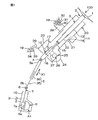
図1は本発明の一実施の形態の伸縮可能シャフトがステアリングシャフト2の一部であるインターミディエイトシャフト5に適用された車両用操舵装置100の概略構成図である。図1を参照して、車両用操舵装置100は、ステアリングホイール等の操舵部材1の操舵力を伝達するステアリングシャフト2を備えている。ステアリングシャフト2は、操舵部材1に連結されたコラムシャフト3と、コラムシャフト3に第1の自在継手4を介して連結された伸縮可能シャフトとしてのインターミディエイトシャフト5と、インターミディエイトシャフト5に第2の自在継手6を介して連結されたピニオンシャフト7とを備えている。
A preferred embodiment of the present invention will be described with reference to the accompanying drawings.
FIG. 1 is a schematic configuration diagram of a
また、車両用操舵装置100は、ピニオンシャフト7の端部近傍に設けられたピニオン7aに噛み合うラック8aを有する転舵軸としてのラックシャフト8とを備えている。ピニオンシャフト7およびラックシャフト8を含むラックアンドピニオン機構によって、転舵機構A1が構成されている。ラックシャフト8は、車体側部材9に固定されたハウジング10によって、車両の左右方向に沿う軸方向(紙面とは直交する方向)に移動可能に、支持されている。ラックシャフト8の各端部は、図示していないが、対応するタイロッドおよび対応するナックルアームを介して対応する転舵輪に連結されている。
Further, the
コラムシャフト3は、第1コラムシャフト11と、第1コラムシャフト11と同軸上に連結れさた第2コラムシャフト12とを備えている。第1コラムシャフト11は、スプライン嵌合を用いて同伴回転可能に且つ軸方向に相対摺動可能に嵌合されたアッパーシャフト13およびロアーシャフト14を有している。
また、第2コラムシャフト12は、ロアーシャフト14と同伴回転可能に連結された入力シャフト15と、第1の自在継手4を介してインターミディエイトシャフト5の第1の端部5aにトルク伝達可能に連結された出力シャフト16と、入力シャフト15および出力シャフト16を相対回転可能に連結するトーションバー17とを有している。一方、インターミディエイトシャフト5の第2の端部5bは、第2の自在継手6を介してピニオンシャフト7にトルク伝達可能に連結されている。
The
Further, the
コラムシャフト3は、車体側部材18,19に固定されたステアリングコラム20によって、図示しない軸受を介して回転可能に支持されている。
ステアリングコラム20は、軸方向に相対移動可能に嵌め合わされた筒状のアッパージャケット21および筒状のロアージャケット22と、ロアージャケット22の軸方向下端に連結されたハウジング23とを備えている。ハウジング23内には、操舵補助用の電動モータ24の動力を減速して出力軸16に伝達する減速機構25が収容されている。
The
The
減速機構25は、電動モータ24の回転軸(図示せず)と同行回転可能に連結された駆動ギヤ26と、駆動ギヤ26に噛み合い出力シャフト16と同伴回転する被動ギヤ27とを有している。駆動ギヤ26は例えばウォーム軸からなり、被動ギヤ27は例えばウォームホイールからなる。
ステアリングコラム20には、車両後方側のアッパーブラケット28および車両前方側のロアーブラケット29を介して車体側部材18,19に固定されている。アッパーブラケット28は、後述するコラムブラケットを介してステアリングコラム20のアッパージャケット21に固定可能とされている。アッパーブラケット28は、車体側部材18から下方に突出する固定ボルト(スタッドボルト)30と、当該固定ボルト30に螺合するナット31と、アッパーブラケット28に離脱可能に保持されたカプセル32とを用いて、車体側部材18に固定されている。
The
The
ロアーブラケット29は、ステアリングコラム20のハウジング23に固定されている。また、ロアーブラケット29は、車体側部材19から突出する固定ボルト(スタッドボルト)33と当該固定ボルト33に螺合するナット34とを用いて、車体側部材19に固定されている。
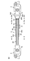
図1および図2に示すように、インターミディエイトシャフト5は、例えばロアーシャフトである内軸35と、例えばアッパーシャフトである筒状の外軸36とを備えている。内軸35および外軸36は、軸方向X1に相対摺動可能に且つ同伴回転可能にスプライン嵌合されている。外軸36の上端が第1の自在継手4の対応するヨーク4aに連結されており、内軸35の下端が第2の自在継手6の対応するヨーク6aに連結されている。
The lower bracket 29 is fixed to the
As shown in FIGS. 1 and 2, the
図2に示すように、外軸36は、開放端である第1の端部361および閉塞端である第2の端部362を有している。外軸36の第2の端部362は第1の自在継手4のヨーク4aの端部に連結され、閉塞されている。内軸35は、第1の端部361側から外軸36内に挿入されて軸方向X1に摺動可能である。
具体的には、内軸35および外軸36がスプライン嵌合されている。すなわち、内軸35の外周は雄スプライン40を有している。また、外軸36の内周は、雄スプライン40と嵌合する雌スプラインとして、第1雌スプライン51および第2雌スプライン52を有している。
As shown in FIG. 2, the
Specifically, the
図2のIII −III 線に沿う断面図である図3に示すように、雄スプライン40の表面40aには、樹脂被膜41が被覆されている。
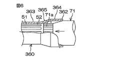
また、図2に示すように、外軸36は、第1の端部361から延び第1雌スプライン51および第2雌スプライン52が形成された小径部363と、第2の端部362から延びる大径部364と、小径部363と大径部364との間に形成されるテーパ部365とを有している。テーパ部365の傾斜角度は、例えば5°〜35°の範囲で適宜に調整されている。
As shown in FIG. 3, which is a cross-sectional view taken along the line III-III in FIG. 2, the
As shown in FIG. 2, the
第1雌スプライン51は、外軸36の第1の端部361から長尺に延びている。第2雌スプライン52は、第1雌スプライン51とテーパ部365との間に配置されている。
本実施の形態の特徴とするところは、第2雌スプライン52の歯面52aに干渉部53が設けられており、その干渉部53が、内軸35を最短縮状態まで短縮させるに伴って内軸の先端部351の樹脂被膜41と干渉することにより、内軸35の最短縮状態を仮保持するようにした点にある。
The first
The feature of the present embodiment is that an
図4(a)は図2のIVa−IVa線に沿う断面図であり、第1雌スプライン51の断面を示している。図4(b)は図2のIVb−IVb線に沿う断面図であり、第2雌スプライン52の断面を示している。
図4(a)に示すように、第1雌スプライン51は、その歯面51aと歯先面51bとのなす第1角R部51cを有しており、図4(b)に示すように、第2雌スプライン52は、その歯面52aと歯先面52bとのなす第2角R部52cを有している。
FIG. 4A is a cross-sectional view taken along line IVa-IVa in FIG. 2 and shows a cross section of the first
As shown in FIG. 4 (a), the first
一方、図3に示すように、内軸35の雄スプライン40の歯溝40bの隅R部40cの曲率半径R3が、外軸36の第1雌スプライン51の第1角R部51cの曲率半径R1と等しく或いは概ね等しくされている(R3≒R1)
第1角R部51cの曲率半径R1よりも、第2角R部52cの曲率半径R2を小さくされている(R2<R1)。したがって、外軸36の第2雌スプライン52の第2角R部52cの曲率半径R2は、内軸35の雄スプライン40の歯溝40bの隅R部40cの曲率半径R3よりも小さいことになる(R2<R3)。
On the other hand, as shown in FIG. 3, the curvature radius R3 of the
The curvature radius R2 of the second
このため、外軸36内へ内軸35を縮めていって最短縮状態になるに伴って、外軸36の第2雌スプライン52の第2角R部52cの一部が、内軸35の先端部351の雄スプライン40の隅R部40cの樹脂被膜41と干渉することになり、その結果、内軸35の最短縮状態を仮保持することができる。すなわち、第2角R部52cの上記一部が、干渉部53を構成することになる。
For this reason, as the
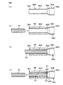
次いで、図5(a)〜(d)は伸縮可能シャフトとしてのインターミディエイトシャフト5の外軸36の製造方法を示している。まず、筒状の素材に絞り加工を施して、図5(a)に示すような、外軸36の製造用中間体360を準備する。製造用中間体360は、第1の端部361と、第2の端部362と、第1の端部361から延びる小径部363と、第2の端部362から延びる大径部364と、小径部と363と大径部364との間に形成されるテーパ部365を有している。ただし、製造用中間体360の小径部363には、未だ雌スプラインが形成されていない点と、製造用中間体360の第2の端部362に第1の自在継手4のヨーク4aが連結されていない点が、完成された外軸36とは異なる。
5A to 5D show a method for manufacturing the
本製造方法は、図5(b)〜(c)に示すように、小径部363の外径を筒状の拘束治具55によって拘束した状態で、ダイ70を第1の端部361側からテーパ部365の直前位置まで挿入するダイ挿入工程と、図5(c)〜(d)に示すように、ダイ70を第1の端部361側へ引き抜くダイ抜脱工程とを含んでいる。
ダイ挿入工程では、ダイ70の挿入に伴って、小径部363の内周に雌スプラインが加工される。次いで、ダイ抜脱工程では、ダイ70を引き抜くときに、雌スプラインの外郭形状にスプリングバックによる膨出が生じる。
In this manufacturing method, as shown in FIGS. 5B to 5C, the
In the die insertion step, a female spline is processed on the inner periphery of the
小径部363の内周の雌スプラインにおいて、テーパ部365の直前位置から所定範囲P1内〔図5(d)参照〕における膨出量が、所定範囲P1外における膨出量よりも大きくなる。すなわち、テーパ部365の剛性が高いので、テーパ部365側へは肉が逃げ難くなり、このため、テーパ部365に隣接する所定範囲P1内におけるスプリングバックによる膨出量が、所定範囲P1外におけるスプリングバックによる膨出量よりも大きくなる。
In the female spline on the inner periphery of the small-
この原理によって、所定範囲P1内に第2雌スプライン52を形成し、且つ所定範囲P1外に第1雌スプライン51を形成することができる。ダイ加工のみで、両雌スプライン51,52の形状の相違を得ることができ、製造コストを安くすることができる。
なお、テーパ部365のテーパ角度が小さいと、スプリングバックによる十分な膨出量が得られないので、テーパ部365のテーパ角度は、例えば5°〜35°の範囲で適宜に調整される。
According to this principle, the second
If the taper angle of the
また、図5(a)〜(d)に示した工程によって、第1雌スプライン51および第2雌スプライン52を形成した後、図6に示す膨出量低減工程によって、膨出量を減少させるように調整するようにしてもよい。すなわち、第2の端部362側から挿入した軸状の歯形矯正治具71によって、上記膨出量を減少させる。歯形矯正治具71の端部は、軸方向X1に沿って第2雌スプライン52の各歯溝にそれぞれ入る矯正歯71aを有している。各矯正歯71aによって歯形を矯正して、上記膨出量を減少させることで、干渉部53の干渉量を精度良く調整することが可能となる。
Further, after the first
また、図5(a)〜(d)に示した工程によって、第1雌スプライン51および第2雌スプライン52を形成した後、図7(a)に示す膨出量増加工程によって、膨出量を増加させるように調整するようにしてもよい。すなわち、第2の端部362側から挿入した軸方向押圧治具72の端面72aの凸部72bによって、第2雌スプライン52の端面52dの歯たけ方向の一部を軸方向X1に押すことにより、図7(b)に示すように、干渉部53Aの膨出量を増加させる。膨出量を増加させることで、干渉部53の干渉量を精度良く調整することが可能となる。
Further, after the first
また、図5(a)〜(d)に示した工程によって、第1雌スプライン51および第2雌スプライン52を形成した後、図8(a)に示す膨出量増加工程によって、膨出量を増加させるように調整するようにしてもよい。すなわち、第2の端部362側から挿入した径方向押圧治具73によって、第2雌スプライン52の歯先面52bを、径方向外方に押すことにより、図8(b)に示すように干渉部53Bの膨出量を増加させる。膨出量を増加させることで、干渉部53の干渉量を精度良く調整することが可能となる。
Further, after the first
径方向押圧治具73は、周方向に複数配列された拡径部材としてのカムフォロワ73aと、カムフォロワ73aの内周の円錐状テーパ面に合致する円錐テーパ状のカム面を有して軸方向移動するカム73bとを有している。径方向押圧治具73は、カムフォロワ73aの外径部によって、第2雌スプライン52の歯先面52bを径方向外方に押す。
本発明は、上記実施の形態に限定されるものではなく、請求項記載の範囲内で種々の変更を施すことができる。
The radial
The present invention is not limited to the above embodiment, and various modifications can be made within the scope of the claims.
1…操舵部材、2…ステアリングシャフト、3…コラムシャフト、5…インターミディエイトシャフト(伸縮可能シャフト)、7…ピニオンシャフト、11…第1コラムシャフト、20…ステアリングコラム、35…内軸、351…先端部、36…外軸、360…製造用中間体、361…第1の端部、362…第2の端部、363…小径部、364…大径部、365…テーパ部、40…雄スプライン、40a…表面、40b…歯溝、40c…隅R部、41…樹脂被膜、51…第1雌スプライン、51a…歯面、51b…歯先面、51c…第1角R部、52…第2雌スプライン、52a…歯面、52b…歯先面、52c…第2角R部、52d…端面、53;53A;53B…干渉部、70…ダイ、71…歯形矯正治具、72…軸方向押圧治具、73…径方向押圧治具、A1…転舵機構、P1…所定範囲、R1…(第1角R部の)曲率半径、R2…(第2角R部の)曲率半径、R3…(隅R部の)曲率半径、X1…軸方向
DESCRIPTION OF SYMBOLS 1 ... Steering member, 2 ... Steering shaft, 3 ... Column shaft, 5 ... Intermediate shaft (expandable shaft), 7 ... Pinion shaft, 11 ... First column shaft, 20 ... Steering column, 35 ... Inner shaft, 351 ...
Claims (9)
上記外軸に上記第1の端部側から挿入され軸方向に摺動可能な内軸と、を備え、
上記外軸の内周が、雌スプラインを含み、
上記内軸の外周が、上記雌スプラインと嵌合する雄スプラインを含み、
上記雄スプラインの表面に、樹脂被膜が形成され、
上記雌スプラインの軸方向の一部が、内軸を最短縮状態まで短縮させるに伴って上記内軸の先端部の上記樹脂被膜と干渉する干渉部を有している伸縮可能シャフト。 A cylindrical outer shaft having first and second ends;
An inner shaft inserted into the outer shaft from the first end side and slidable in the axial direction,
The inner circumference of the outer shaft includes a female spline,
The outer periphery of the inner shaft includes a male spline that fits with the female spline,
A resin film is formed on the surface of the male spline,
A telescopic shaft in which a portion of the female spline in the axial direction has an interference portion that interferes with the resin coating at the tip of the inner shaft as the inner shaft is shortened to the shortest state.
上記小径部の上記雌スプラインは、上記第1の端部から延びる第1雌スプラインと、上記第1雌スプラインと上記テーパ部との間に配置された第2雌スプラインと、を有し、
上記第2雌スプラインに、上記干渉部が設けられている伸縮可能シャフト。 2. The outer shaft according to claim 1, wherein the outer shaft extends from the first end portion, has a small diameter portion formed with the female spline, a large diameter portion extends from the second end portion, the small diameter portion, and the large diameter portion. A taper portion formed between and
The female spline of the small diameter portion includes a first female spline extending from the first end portion, and a second female spline disposed between the first female spline and the tapered portion,
A telescopic shaft in which the interference portion is provided on the second female spline.
第1の端部、第2の端部、上記第1の端部から延びる小径部、上記第2の端部から延びる大径部、および上記小径部と上記大径部との間に形成されるテーパ部を含む筒状の製造用中間体内へ、上記第1の端部側から上記テーパ部の直前位置までダイを挿入するダイ挿入工程と、
上記ダイを第1の端部側へ引き抜くダイ抜脱工程と、を含み、
上記ダイ挿入工程では、外軸内へのダイの挿入に伴って、上記小径部に雌スプラインが加工され、
上記ダイ抜脱工程では、外軸からダイを引き抜くときに、上記雌スプラインの外郭形状にスプリングバックによる膨出を生じさせ、テーパ部の直前位置から所定範囲内における膨出量を、所定範囲外における膨出量よりも大きくすることにより、上記所定範囲内に第2雌スプラインを形成し、且つ上記所定範囲外に第1雌スプラインに形成するようにしている伸縮可能シャフトの製造方法。 In the manufacturing method of the telescopic shaft according to any one of claims 2 to 4,
A first end, a second end, a small diameter portion extending from the first end, a large diameter portion extending from the second end, and a portion between the small diameter portion and the large diameter portion. A die insertion step of inserting a die from the first end side to a position immediately before the tapered portion into a cylindrical manufacturing intermediate including a tapered portion;
A die removing step of drawing the die to the first end side,
In the die insertion step, with the insertion of the die into the outer shaft, a female spline is processed in the small diameter portion,
In the die pulling-out step, when the die is pulled out from the outer shaft, the outer shape of the female spline is caused to bulge by a spring back, and the bulging amount within the predetermined range from the position immediately before the tapered portion is outside the predetermined range. A method of manufacturing a telescopic shaft, wherein the second female spline is formed within the predetermined range and the first female spline is formed outside the predetermined range by making the amount larger than the bulging amount in the first step.
Priority Applications (1)
| Application Number | Priority Date | Filing Date | Title |
|---|---|---|---|
| JP2010265446A JP5582987B2 (en) | 2010-11-29 | 2010-11-29 | Extendable shaft, method of manufacturing the same, and vehicle steering device |
Applications Claiming Priority (1)
| Application Number | Priority Date | Filing Date | Title |
|---|---|---|---|
| JP2010265446A JP5582987B2 (en) | 2010-11-29 | 2010-11-29 | Extendable shaft, method of manufacturing the same, and vehicle steering device |
Publications (3)
| Publication Number | Publication Date |
|---|---|
| JP2012117560A true JP2012117560A (en) | 2012-06-21 |
| JP2012117560A5 JP2012117560A5 (en) | 2013-08-22 |
| JP5582987B2 JP5582987B2 (en) | 2014-09-03 |
Family
ID=46500646
Family Applications (1)
| Application Number | Title | Priority Date | Filing Date |
|---|---|---|---|
| JP2010265446A Active JP5582987B2 (en) | 2010-11-29 | 2010-11-29 | Extendable shaft, method of manufacturing the same, and vehicle steering device |
Country Status (1)
| Country | Link |
|---|---|
| JP (1) | JP5582987B2 (en) |
Cited By (3)
| Publication number | Priority date | Publication date | Assignee | Title |
|---|---|---|---|---|
| WO2015015952A1 (en) | 2013-07-30 | 2015-02-05 | 日本精工株式会社 | Torque transmission shaft with yoke for universal joint and manufacturing method therefor |
| EP2998190A1 (en) | 2014-09-04 | 2016-03-23 | Jtekt Corporation | Intermediate shaft |
| WO2018167992A1 (en) * | 2017-03-16 | 2018-09-20 | 株式会社ショーワ | Spline fitting body and method for manufacturing spline fitting body |
Citations (5)
| Publication number | Priority date | Publication date | Assignee | Title |
|---|---|---|---|---|
| JPH11247835A (en) * | 1998-03-04 | 1999-09-14 | Nippon Seiko Kk | Hollow steering shaft, its manufacture, and tool for manufacturing hollow steering shaft |
| JP2002264825A (en) * | 2001-03-09 | 2002-09-18 | Koyo Seiko Co Ltd | Intermediate shaft for steering device |
| JP2004217095A (en) * | 2003-01-15 | 2004-08-05 | Nsk Ltd | Telescopic shaft for vehicle steering |
| JP2004324863A (en) * | 2003-04-28 | 2004-11-18 | Koyo Seiko Co Ltd | Telescopic shaft |
| JP2006123820A (en) * | 2004-10-29 | 2006-05-18 | Nsk Ltd | Telescopic shaft for vehicle steering |
-
2010
- 2010-11-29 JP JP2010265446A patent/JP5582987B2/en active Active
Patent Citations (5)
| Publication number | Priority date | Publication date | Assignee | Title |
|---|---|---|---|---|
| JPH11247835A (en) * | 1998-03-04 | 1999-09-14 | Nippon Seiko Kk | Hollow steering shaft, its manufacture, and tool for manufacturing hollow steering shaft |
| JP2002264825A (en) * | 2001-03-09 | 2002-09-18 | Koyo Seiko Co Ltd | Intermediate shaft for steering device |
| JP2004217095A (en) * | 2003-01-15 | 2004-08-05 | Nsk Ltd | Telescopic shaft for vehicle steering |
| JP2004324863A (en) * | 2003-04-28 | 2004-11-18 | Koyo Seiko Co Ltd | Telescopic shaft |
| JP2006123820A (en) * | 2004-10-29 | 2006-05-18 | Nsk Ltd | Telescopic shaft for vehicle steering |
Cited By (6)
| Publication number | Priority date | Publication date | Assignee | Title |
|---|---|---|---|---|
| WO2015015952A1 (en) | 2013-07-30 | 2015-02-05 | 日本精工株式会社 | Torque transmission shaft with yoke for universal joint and manufacturing method therefor |
| US9915291B2 (en) | 2013-07-30 | 2018-03-13 | Nsk Ltd. | Torque transmission shaft having universal joint yoke and method of manufacturing the same |
| EP2998190A1 (en) | 2014-09-04 | 2016-03-23 | Jtekt Corporation | Intermediate shaft |
| US9618052B2 (en) | 2014-09-04 | 2017-04-11 | Jtekt Corporation | Intermediate shaft |
| WO2018167992A1 (en) * | 2017-03-16 | 2018-09-20 | 株式会社ショーワ | Spline fitting body and method for manufacturing spline fitting body |
| JP2018155291A (en) * | 2017-03-16 | 2018-10-04 | 株式会社ショーワ | Spline fitting body |
Also Published As
| Publication number | Publication date |
|---|---|
| JP5582987B2 (en) | 2014-09-03 |
Similar Documents
| Publication | Publication Date | Title |
|---|---|---|
| US9469332B2 (en) | Coupling structure for coupling shaft to universal joint yoke, coupling method for coupling shaft to universal joint yoke, and intermediate shaft | |
| EP3085603B1 (en) | Telescoping spline shaft and steering device | |
| JP6201986B2 (en) | Rotation transmission mechanism and electric power steering device | |
| JP5130915B2 (en) | Electric power steering device | |
| JP5508243B2 (en) | Steering transmission shaft and universal joint yoke coupling structure and vehicle steering device | |
| JP5582987B2 (en) | Extendable shaft, method of manufacturing the same, and vehicle steering device | |
| EP2666700A1 (en) | Steering device | |
| JP6471552B2 (en) | Retaining ring and worm reducer | |
| US10099718B2 (en) | Electric power steering device and method for assembling the same | |
| JP2012112416A (en) | Telescopic shaft and vehicle steering device | |
| JP2014015130A (en) | Steering device | |
| JP6135310B2 (en) | Worm reducer and dual pinion type electric power steering device | |
| JP2006001423A (en) | Vehicular steering device, and its assembling method | |
| JP5641333B2 (en) | Telescopic shaft and vehicle steering device | |
| JP5636828B2 (en) | Universal joint and processing method thereof | |
| JP5370201B2 (en) | Universal joint yoke | |
| JP5233656B2 (en) | Electric power steering device | |
| JP2015155745A (en) | Worm reduction gear and dual pinion type electric power steering device | |
| JP2009190670A (en) | Electric power steering device | |
| JP4586384B2 (en) | Gear manufacturing method and gear manufacturing jig | |
| JP2019181991A (en) | Shaft unit, manufacturing method of the same, and steering unit | |
| JP5920582B2 (en) | Steering device and manufacturing method thereof | |
| JP2008298148A (en) | Method of manufacturing gear transmission device and positioning tool | |
| JP2020016299A (en) | Joint | |
| JP2017132375A (en) | Electric power steering device |
Legal Events
| Date | Code | Title | Description |
|---|---|---|---|
| A521 | Request for written amendment filed |
Free format text: JAPANESE INTERMEDIATE CODE: A523 Effective date: 20130708 |
|
| A621 | Written request for application examination |
Free format text: JAPANESE INTERMEDIATE CODE: A621 Effective date: 20130708 |
|
| A977 | Report on retrieval |
Free format text: JAPANESE INTERMEDIATE CODE: A971007 Effective date: 20131113 |
|
| A131 | Notification of reasons for refusal |
Free format text: JAPANESE INTERMEDIATE CODE: A131 Effective date: 20140220 |
|
| A521 | Request for written amendment filed |
Free format text: JAPANESE INTERMEDIATE CODE: A523 Effective date: 20140327 |
|
| TRDD | Decision of grant or rejection written | ||
| A01 | Written decision to grant a patent or to grant a registration (utility model) |
Free format text: JAPANESE INTERMEDIATE CODE: A01 Effective date: 20140626 |
|
| A61 | First payment of annual fees (during grant procedure) |
Free format text: JAPANESE INTERMEDIATE CODE: A61 Effective date: 20140715 |
|
| R150 | Certificate of patent or registration of utility model |
Ref document number: 5582987 Country of ref document: JP Free format text: JAPANESE INTERMEDIATE CODE: R150 |
|
| S533 | Written request for registration of change of name |
Free format text: JAPANESE INTERMEDIATE CODE: R313533 |
|
| R350 | Written notification of registration of transfer |
Free format text: JAPANESE INTERMEDIATE CODE: R350 |