JP2012117257A - Bathroom structure - Google Patents
Bathroom structure Download PDFInfo
- Publication number
- JP2012117257A JP2012117257A JP2010266818A JP2010266818A JP2012117257A JP 2012117257 A JP2012117257 A JP 2012117257A JP 2010266818 A JP2010266818 A JP 2010266818A JP 2010266818 A JP2010266818 A JP 2010266818A JP 2012117257 A JP2012117257 A JP 2012117257A
- Authority
- JP
- Japan
- Prior art keywords
- floor
- wall
- bathroom
- wall surface
- base material
- Prior art date
- Legal status (The legal status is an assumption and is not a legal conclusion. Google has not performed a legal analysis and makes no representation as to the accuracy of the status listed.)
- Granted
Links
Images


Abstract
Description
本発明の態様は、浴室の床面材として発泡プラスチックを用いた浴室構造に関する。 An aspect of the present invention relates to a bathroom structure using foamed plastic as a flooring material for a bathroom.
浴室の床面を構成する床面材として発泡プラスチックを用いた浴室構造が、開示されている(特許文献1)。この浴室構造では、洗い場部分は、底板の上に発泡プラスチックで形成した床面材を載せた二層構造になっており、底板は床の強度を担う床基材としての役目を果たしている。 A bathroom structure using foamed plastic as a floor material constituting the floor surface of the bathroom is disclosed (Patent Document 1). In this bathroom structure, the washing area has a two-layer structure in which a floor material made of foamed plastic is placed on the bottom plate, and the bottom plate plays a role as a floor base material that bears the strength of the floor.
一般的に、浴室の床の洗い場部分には排水勾配を設ける必要があるが、このような二層構造では、製造上の理由から、下層の補強層となる床基材には入手容易な平板状の板材を用いて、上層の発泡プラスチックで形成される床面材にこの排水勾配を設けることがある。その場合、床面材は外縁部から排水口部にかけて肉厚が徐々に薄くなるため全体として、床面側を内面とする凹形状となる。 In general, it is necessary to provide a drainage gradient in the washing area of the bathroom floor. However, in such a two-layer structure, a flat base plate that is easily available as a lower reinforcing layer is used for the reason of manufacturing. This drainage gradient may be provided on a floor material formed of an upper foamed plastic using a plate-like plate material. In that case, since the thickness of the floor surface material gradually decreases from the outer edge portion to the drain port portion, the floor surface material has a concave shape with the floor surface side as the inner surface as a whole.
一方、発泡プラスチックは、通常では発泡成形という方法によって所望の形状に型成形されるが、成形収縮率が通常用いられている樹脂材料の中では比較的大きく、成形条件等で調整を行ったとしても成形時に「反り(ソリ)」などといわれる変形が発生しやすい。そして、このような「反り」は、成型品の厚みが均一でない場合に、特に顕著になりやすい。例えば凹形状の場合には、この凹形状が「反り」の要因として加味され、凹面側への変形が大きくなり易く、用途によってはこの変形が問題となる場合がある。 On the other hand, foamed plastics are usually molded into a desired shape by a method called foam molding, but the molding shrinkage rate is relatively large among the resin materials that are usually used, and it is adjusted according to molding conditions, etc. However, deformation called warping is likely to occur during molding. Such “warping” is particularly prominent when the thickness of the molded product is not uniform. For example, in the case of a concave shape, this concave shape is taken into account as a factor of “warping”, and the deformation toward the concave surface tends to be large, and this deformation may be a problem depending on the application.
即ち、この特許文献1に記載された例のように発泡プラスチック成形品によって凹形状の床面材を形成した場合、床面材には床表面側に凹となる変形が大きくなる傾向が生じる。その結果、この床面材を平坦な底板上に載置した際には、底板の表面と床面材の裏面との間の密着度が低下し、そのままでは使用時に人が床面を歩くと上下方向へのガタつきを感じることになる。その対策として、接着剤等を床面材と床基材の少なくともどちらか一方に全面塗布してこの二層を貼り合わせて一体化する方法も考えられるが、製造工程の煩雑化を招き、トータルコストの上昇を招くという問題が生じる。
That is, when a concave floor surface material is formed by a foamed plastic molded product as in the example described in
本発明は、かかる課題の認識に基づいてなされたものであり、発泡プラスチックを床面材に用いた浴室構造において、特別な施工を必要とせず、容易かつ確実に床面材を床基材に密着させることによって、床面材の設計上の位置出しを正確に行うことができる浴室構造を提供することを目的とする。 The present invention has been made on the basis of recognition of such a problem, and in a bathroom structure using foamed plastic as a flooring material, no special construction is required, and the flooring material is easily and reliably used as a floor base material. An object of the present invention is to provide a bathroom structure capable of accurately positioning the flooring material by being brought into close contact.
第1の発明は、浴室設置面の上に設置される床保持部材と、前記床保持部材の上に固定して設けられる床基材と、前記床基材の上面に接して設けられ、発泡プラスチックで形成された床面材と、前記浴室の立ち壁面を形成する壁面材と、を備え、前記壁面材は、前記床面材の外縁部を前記床基材に向けて、直線状に押圧することを特徴とする浴室構造である。 1st invention is provided in contact with the upper surface of the floor holding member installed on the bathroom installation surface, the floor base material fixed on the floor holding member, and the floor base material, and foaming A floor surface material made of plastic and a wall surface material forming a standing wall surface of the bathroom, and the wall surface material is linearly pressed with an outer edge portion of the floor surface material facing the floor base material It is a bathroom structure characterized by doing.
この浴室構造によれば、発泡プラスチックによる床面材は成形時に発生した反りのため凹形状となっていても、その外縁部が壁面材からの押圧を受けることによって、凹形状の最深部を床基材に当たる支点として平面の床基材に倣うように変形が矯正されて排水勾配が設計通りとなり、床面材の設計上の位置出しを正確に行うことができる。さらにこれにより、床基材に対して床面材の浮きがなくなり両者が密着することで、床面として一体感を得られるようになる。その結果として、使用者の感じる床感触の不快感の発生を防止することができる。 According to this bathroom structure, even if the floor surface material made of foamed plastic has a concave shape due to warpage generated during molding, the outer edge of the floor material is pressed by the wall surface material, so that the deepest portion of the concave shape is As a fulcrum hitting the base material, the deformation is corrected so as to follow a flat floor base material, the drainage gradient becomes as designed, and the floor surface material can be accurately positioned. Further, the floor material is not lifted with respect to the floor base material, and both come into close contact with each other, so that a sense of unity can be obtained as the floor surface. As a result, it is possible to prevent occurrence of uncomfortable feeling of floor feeling that the user feels.
また、第2の発明は、浴室設置面の上に設置される床保持部材と、前記床保持部材の上に固定して設けられる床基材と、フランジ状の外縁部を有して前記床基材の上面に接して設けられ、発泡プラスチックで形成された床面材と、前記浴室の立ち壁面を形成する壁面材と、前記壁面材の下端部と浴室床面との接続部の止水構造となる溝部を有して前記壁面材の下端部と前記床面材の外縁部との間に設けられた床面材枠と、を備え、前記壁面材は、前記下端部が前記溝部に設けられた凹部に挿入されることによって、前記外縁部を前記床基材に向けて、線状に押圧することを特徴とする浴室構造である。 Moreover, 2nd invention has the floor holding member installed on the bathroom installation surface, the floor base material fixedly provided on the said floor holding member, and a flange-shaped outer edge part, and said floor A floor material provided in contact with the upper surface of the base material and formed of foamed plastic, a wall material forming a standing wall surface of the bathroom, and a water stop of a connection portion between the lower end of the wall material and the bathroom floor surface A floor surface material frame provided between a lower end portion of the wall surface material and an outer edge portion of the floor surface material having a groove portion to be a structure, and the lower surface portion of the wall surface material in the groove portion The bathroom structure is characterized in that the outer edge portion is linearly pressed toward the floor base material by being inserted into the provided recess.
この浴室構造によれば、発泡プラスチックによる床面材は成形時に発生した反りのため凹形状となっていても、その外縁部が壁面材からの押圧を受けることによって、凹形状の最深部を床基材に当たる支点として平面の床基材に倣うように変形が矯正されて排水勾配が設計通りとなり、床面材の設計上の位置出しを正確に行うことができる。また、床面材は複雑な形状の溝部が無くなり、フランジ状の外縁部だけの単純な形状となるため、成形加工が容易となる。 According to this bathroom structure, even if the floor surface material made of foamed plastic has a concave shape due to warpage generated during molding, the outer edge of the floor material is pressed by the wall surface material, so that the deepest portion of the concave shape is As a fulcrum hitting the base material, the deformation is corrected so as to follow a flat floor base material, the drainage gradient becomes as designed, and the floor surface material can be accurately positioned. Further, the floor material has no complicated groove portion and has a simple shape with only a flange-like outer edge portion, so that the molding process becomes easy.
また、第3の発明は、第1または第2の発明において、複数の前記壁面材と、前記複数の壁面材どうしを連接する壁面接続部材と、前記壁面接続部材を前記床基材または前記床保持部材に固定する壁面固定部材と、をさらに備え、前記壁面接続部材及び前記壁面固定部材のうち少なくとも一方で前記外縁部を下方に押圧することを特徴とする浴室構造である。 Moreover, 3rd invention is 1st or 2nd invention. WHEREIN: The said wall surface material, the wall surface connection member which connects these wall surface materials, and the said wall surface connection member are said floor base material or said floor And a wall surface fixing member fixed to the holding member, wherein the outer edge portion is pressed downward at least one of the wall surface connection member and the wall surface fixing member.
この浴室構造によれば、浴室を組み立てるとき、壁面固定部材または壁面接続部材で床面材を床基材に対して仮固定できるため、その後に壁面材どうしを連接する壁面材設置作業行程時に床面材が移動することを防止して組み付け作業を正確にかつ素早く行うことができるようになる。 According to this bathroom structure, when assembling the bathroom, the floor surface material can be temporarily fixed to the floor base material with the wall surface fixing member or the wall surface connecting member. The face material is prevented from moving, and the assembling work can be performed accurately and quickly.
また、第4の発明は、第1〜第3のいずれかの発明において、前記床面材に設けられた排水口と浴室内で使用した水を排出するための排水管路とを接続する配管接続部材をさらに備え、前記配管接続部材を前記床基材または前記床保持部材に対して固定するとともに、前記配管接続部材を前記排水口に取り付けることによって、前記床面材の排水口を前記床基材に対して固定したことを特徴とする浴室構造である。 Moreover, 4th invention is piping in which the drain outlet provided in the said floor surface material and the drain pipe for discharging the water used in the bathroom in any one of 1st-3rd invention are connected. Further comprising a connecting member, fixing the pipe connecting member to the floor base material or the floor holding member, and attaching the pipe connecting member to the drain outlet, thereby connecting the drain outlet of the floor surface material to the floor It is the bathroom structure characterized by being fixed with respect to the base material.
この浴室構造によれば、浴室の構築に必須の部材を使用することによって、床面材の固定のみならず、排水勾配の起点となる排水口部の位置出しを確実に行うことができるようになり、浴室床で重要な設計要素である排水勾配を正確に設定した施工が可能となる。 According to this bathroom structure, by using the members essential for the construction of the bathroom, not only fixing of the flooring material, but also the positioning of the drainage port that becomes the starting point of the drainage gradient can be performed reliably. Therefore, it is possible to construct the drainage gradient, which is an important design element on the bathroom floor, accurately.
本発明の態様によれば、発泡プラスチックを床面材に用いた浴室構造において、通常の浴室構造では使用されることのない押圧専用の部材や特別な施工を必要とせず、容易かつ確実に床面材を床基材に密着させることによって、床面材の設計上の位置出しを正確に行うことができる浴室構造が提供される。 According to the aspect of the present invention, in a bathroom structure using foamed plastic as a floor surface material, it is possible to easily and surely perform a floor without requiring a dedicated member or special construction that is not used in a normal bathroom structure. By bringing the face material into close contact with the floor base material, a bathroom structure capable of accurately positioning the floor face material in design is provided.
以下、本発明を適用した実施形態について図面を参照しつつ説明する。なお、各図面中、同様の構成要素には同一の符号を付して詳細な説明は適宜省略する。
図1は、本実施形態にかかる浴室構造を備えた浴室ユニットを例示する模式的斜視図である。
Embodiments to which the present invention is applied will be described below with reference to the drawings. In addition, in each drawing, the same code | symbol is attached | subjected to the same component and detailed description is abbreviate | omitted suitably.
FIG. 1 is a schematic perspective view illustrating a bathroom unit including a bathroom structure according to this embodiment.
図1に示した浴室ユニットは、浴槽1と、洗い場床2と、壁3と、を備えている。
浴槽1の底部裏面における四隅近傍には、支持脚6が設けられ、その支持脚6を介して、浴槽1は浴室設置面(例えば、建物の床)Sの上に設置される。支持脚6は、ボルト部を回転させることで高さ調節可能な構造を有する。
The bathroom unit shown in FIG. 1 includes a
洗い場床2は、周縁部が上側に折り曲げられた浅底の器状(パン状)に形成され、浴室外部に湯水を漏出させない防水性を有する。そして、ボルト部を回転させることで高さ調節可能な構造を有する支持脚231を介して浴室設置面S上に設置されている。
The
洗い場床2において、浴槽1との境界部近傍には、排水管5に連通する排水口(図1では、着脱自在の蓋25で塞がれている。)が形成されている。排水口が設けられた部分はくぼんでおり、洗い場床2の表面には、排水口に向けて下向き傾斜した排水勾配が付けられている。洗い場床2の裏側において、浴槽1との境界部近傍には排水管5が設けられ、排水口は排水管5に接続されている。また、浴槽1の底部に設けられた図示しない排水口も、排水管5に接続されている。
In the
壁3は、浴室ユニットの4面を構成しており、本発明の壁面材である第1〜第6の壁パネル31〜36を有し、隣接する壁パネルの間には、隣接する壁パネル同士を連接する壁面接続部材50が洗い場床2の外周部2aに立設されている。
The
第1の壁パネル31は、洗い場床2の浴槽1とは反対側に配置されており、2枚の壁パネルが図示しない壁面接続部材50によって連接されて形成されている。第2の壁パネル32及び第3の壁パネル33は、第1の壁パネル31と直交し、互いに対向して配置されている。第4〜第6の壁パネル34〜36は、浴槽1の縁のうち、洗い場床2側を除く3辺の縁の上に配置されている。第4の壁パネル34及び第5の壁パネル35の下側には、浴槽1と第2の壁パネル32及び第3の壁パネル33との間をつなぐ小パネル37が設けられている。小パネル37も、本発明の壁面材の一つである。
The
なお、本発明における壁面材の構成は、洗い場床2に対して立ち壁面を構成して洗い場床2を押圧するものであれば良く、上記第1〜第6の壁パネル31〜36及び小パネル37には限定されず、1枚のパネルが複数パネルに分割されている構成や、隣接する複数枚のパネルが一体化されている構成であってもよい。
また、図1に例示した浴室ユニットでは、第3の壁パネル33には図示しないドア取付枠を介してドアDRが設けられている。本発明では、ドア取付枠を含んだ壁パネル33も壁面材に含まれるものとする。
In addition, the structure of the wall surface material in this invention should just comprise a standing wall surface with respect to the washing-
In the bathroom unit illustrated in FIG. 1, the
浴槽1と洗い場床2との境界には、浴槽1における洗い場床2側の側面を覆い隠すバスエプロン9が設けられている。本実施形態では、バスエプロン9も後述するように床面材を押圧しており、本発明の壁面材の一つに含めるものとする。なお、浴槽1の構造によっては、バスエプロン9を設けなくてよいものもある。
A
図2は、洗い場床2の構成を説明する模式的分解斜視図である。
図3は、洗い場床2と本発明における壁面材を構成する壁面パネルとの関係を説明する模式図であり、図3(a)は模式的斜視図、図3(b)は図3(a)のA−A’線矢視の模式的断面図である。
図2に表したように、洗い場床2は、下から順に、床保持部材23、床基材22、床面材21、クッション材201及び表皮材202を有する。
FIG. 2 is a schematic exploded perspective view illustrating the configuration of the
FIG. 3 is a schematic view for explaining the relationship between the
As illustrated in FIG. 2, the
床保持部材23は、支持平面を形成する支持フレーム232と、支持フレーム232の4隅に設けられる4本の支持脚231と、を有する。床保持部材23は、浴室設置場所の限られた垂直方向のスペースの中において、洗い場床2の上面にかかる浴室の使用者を含んだ全ての荷重を受けてその位置を保持するものであり、そのために充分な強度が必要とされる。従って、この充分な強度が得られる一例として、本実施形態では鋼材が用いられている。
The
支持脚231は、前述した荷重を受けるだけでなく、洗い場床2の水平面出しを行うために、ボルト部を回転させることで高さ調節可能な構造を有している。
The
支持フレーム232は、第1の方向に配置された例えば2本の第1フレーム232aと、第1の方向と直交する第2の方向に配置された例えば4本の第2フレーム232bと、を有する。第2フレーム232bは、2本の第1フレーム232aの間をつなぐように配置されている。
The
支持フレーム232の上には床基材22が載置され、ネジ等の締結部材で固定される。床基材22は、その上面が洗い場床2を構成する各部材の垂直方向の位置基準となる水平基準面となり、かつ、その上に載置される部材からの荷重を受けるものでもあり、支持フレーム232に固定される。そのため、床基材22には比較的に高強度で剛性のある平板状の素材が好適であり、その一例として、サンドイッチパネルが用いられている。サンドイッチパネルは、例えばプラスチックの板材を2枚の鋼板で挟んだ構造であり、比較的軽量にもかかわらず剛性が高く、ネジなどの締結部材も使用できる素材である。
なお、床基材22の略中央には、例えば施工の際に支持脚231の高さ調節による床基材22の水平出し作業等のため、作業者が床下にもぐることができるように作業口221hが設けられている。施工後、この作業口221hには蓋221が被せられる。
The
In addition, in the center of the
床基材22の上には、床面材21がその裏面を接して載置されることにより、床面材21は、床基材22の表面(上面)を基準にして配置されることになる。
The
床面材21は、発泡プラスチックによって形成され、後述するように、排水口となる凹形状部や洗い場床2の排水勾配を形成するための傾斜面や外縁部の止水壁等の3次元形状が付与されている。
The
なお、発泡プラスチックとしては、例えば発泡ポリプロピレン、発泡ポリスチレン、発泡ポリエチレン、発泡ポリウレタンが用いられる。本実施形態では、一例として発泡ポリプロピレンが用いられている。発泡ポリプロピレンは、他の発泡プラスチックに比べてリサイクル性が高いため、これを用いることで環境に優しい製品を提供できることになる。 For example, foamed polypropylene, foamed polystyrene, foamed polyethylene, and foamed polyurethane are used as the foamed plastic. In this embodiment, foamed polypropylene is used as an example. Foamed polypropylene is more recyclable than other foamed plastics, so using this makes it possible to provide environmentally friendly products.
本実施形態では、床面材21の上には、クッション材201を介して表皮材202が設けられている。これらの部材はいずれも、洗い場床2の床面の外観意匠や使用感などの官能的な性能向上や、防水性などの洗い場床2に必然的に求められる機能を向上させるために用いられている。
In the present embodiment, a
即ち、クッション材201は、使用者に与える床面の柔らかさを得るもので、例えば発泡ポリウレタン等の軟質素材が用いられている。クッション材201の硬さ(柔らかさ)を変えることで、床面の硬さ(柔らかさ)の仕様を変更することができる。
That is, the
表皮材202は、洗い場床2の表面を形成するもので、防水性を有する可撓性を有する軟質シート材が用いられている。表皮材202には、洗い場床2の表面の意匠性や水はけ性を向上させるために、凹凸加工や柄模様を施したりすることも可能である。
The
なお、これらの各部材は、浴室ユニットを施工する前において、床面材21の表面にクッション材201及び表皮材202を予め貼り付けた組品である床面部材として構成されている。床面材21が軽量な発泡プラスチックによって形成されていることから、このように予め組品を構成しておいても、十分な軽さを得たまま、施工作業を行うことができる。
Each of these members is configured as a floor surface member that is an assembly in which the
図3は本実施形態における洗い場床2と壁3との関係を示すもので、説明の便宜上、いずれの図も前述したクッション材201及び表皮材202を省略している。床面材21は、図3(a)に表したように、浴槽に接する一辺には排水口26が設けられ、その表面にはこの排水口26を基準とした洗い場床に必須な配水勾配が設けられている。また、外縁部21aの表面側には後で詳述するように、壁面材が挿入される凹部や防水壁となる立壁等の、従来の洗い場床でも採用されている防水パンとして必要な形状が本発明における溝部として形成されている。
FIG. 3 shows the relationship between the
さらに、図3(b)に表したように、床面材21は、支持フレーム232上に載置された床基材22の表面に裏面が接した状態で設けられている。
Furthermore, as shown in FIG. 3B, the
その外縁部21aは、表面側に形成された溝部に挿入される壁面構成部材である壁3の自重によって裏面に配置されている床基材22に向けて押圧されている。具体的には、第1〜第3の壁パネル31〜33によって床面材21の3辺に対応した外縁部21aを、表面側から裏面側に向けて押圧している。
The
このように本実施形態では、洗い場床2の床面の基本構造を、浴室床として必要な強度を補強する床基材22と、その上に載置されて浴室床として必要な形状を担う床面材21とで構成とすることにより、従来用いられてきたFRP(Fiber Reinforced Plastics)素材を基本構造とする場合と比較して、浴室床として大幅なコストダウンとなる効果が得られている。
As described above, in this embodiment, the basic structure of the floor surface of the
即ち、浴室床として必要な形状を発泡プラスチックによって形成することにより、大尺なため高価となる型を使用して形状付与を行う型成形において、従来用いられてきたFRP素材での成形と比較して安価な型を使用出来るようになるため、成形品の製造コストを大幅に引き下げることが可能となるだけでなく、浴室床として必要なもう一つの要求品質である強度面を主として単純な形状である平板状の安価な素材に持たせることが可能となっている。 In other words, by forming the shape required for the bathroom floor with foamed plastic, in the mold forming that gives the shape using a mold that is large and expensive, compared with the molding using the FRP material that has been conventionally used. This makes it possible not only to greatly reduce the manufacturing cost of the molded product, but also to provide another required quality as a bathroom floor, mainly with a simple shape. It can be applied to a certain flat and inexpensive material.
その結果として、浴室床を構成する各部材毎の重量を軽くすることができ、運搬や設置など施工作業が行いやすくなるだけでなく、大尺な浴室床の製造コストを大幅に引き下げることが可能となる。 As a result, the weight of each component of the bathroom floor can be reduced, which not only facilitates construction work such as transportation and installation, but also greatly reduces the cost of manufacturing large bathroom floors. It becomes.
ここで、床面材21の表面には、前述したように、配水勾配が設けられているため、床面材21の外縁部21aと排水口26の近傍とでは肉厚に差が生じて全体的にみると表面側が凹の形状となっている。このため、床面材21の成形品には、定性的に表面側がさらに凹となる方向に変形が生じる傾向となることが我々の実験によって確かめられた。そして、このような変形が生じた床面材21を床基材22の表面に接するように載置すると、床基材22の表面に対して床面材21の外縁部21aで浮き上がりが発生することとなる。
Here, since the water distribution gradient is provided on the surface of the
そのため本実施形態では、前述したように床面材21の外縁部21aを壁3によって線状に押圧している。そうすることにより、壁3を組み立てるときに、壁3の自重によって床面材21を床基材22の表面に倣わせて凹状の変形を矯正することが可能になる。つまり、本実施形態では、成形時に定性的に生じるソリによる変形の性質と浴室構造に必須な構成部材とをうまく組み合わせて利用することによって、接着剤塗布などの別工程や固定のためだけの別部材を必要としないで、発泡プラスチックの床面材21を容易かつ確実に床基材22上に実用上問題の発生しない程度にまで密着させることが可能になる。
Therefore, in this embodiment, the
図4及び図5は、壁による床面材の押圧構造の具体例を例示した模式的拡大断面図であり、図4は、本実施形態で採用しているクッション材201と表皮材202とを使用しない構成において本発明を実施した具体例を示したものである。また、図5はそれらを使用する本実施形態で採用している構成において本発明を実施した具体例の詳細構造を示したものである。
なお、図4では、説明の便宜上、本実施形態に対応させて同様の構成要素には同一の符号を付している。また、いずれも第1の壁パネル31の部分についての押圧の構造の具体例を例示するが、第2及び第3の壁パネル32及び33並びに小パネル37の部分であっても同様である。
4 and 5 are schematic enlarged cross-sectional views illustrating specific examples of the pressing structure of the floor surface material by the wall, and FIG. 4 shows the
In FIG. 4, for convenience of explanation, the same reference numerals are given to similar components corresponding to the present embodiment. In addition, although specific examples of the pressing structure for the portion of the
図4(a)に表した具体例では、本実施形態と同様に、床面材の外縁部を壁面材で直接的に押圧する場合を例示している。即ち、床面材21の外縁部21aには壁面材が挿入される凹部や防水壁となる立壁等を有して浴室床面との接続部の止水構造を形成する断面視凹形状の溝部21bが設けられており、この溝部21bの凹部に壁面材に相当する第1の壁パネル31の下部が挿入され、凹部の底面にその下端31aが当接するようになっている。なお、凹部と第1の壁パネル31との隙間にはコーキング材CKが設けられて、浴室内の水が壁パネル31の裏面側に回りこむことを防いでいる。
In the specific example shown in FIG. 4A, the case where the outer edge portion of the floor surface material is directly pressed by the wall surface material is illustrated as in the present embodiment. In other words, the
図4(b)、(c)は、本発明のうちの一つを適用して、外縁部21aの溝部21bを形成する部分を別体の部材で構成した場合の具体例を示している。即ち、本具体例における床面材211は、本実施形態における床面材21の溝部21bに相当する部分が別体の部材の床面材枠212として分離され、本発明の外縁部に相当する外周部にフランジ形状をした床面材ツバ211aが設けられただけの単純な形状になっている。そして、図4(b)、(c)は互いに床面材ツバ211aと第1の壁パネル31との水平方向の位置関係が互いに異なるが、いづれも床面材枠212がこの床面材ツバ211aを上方から押さえ込む形になるように構成されている。
4 (b) and 4 (c) show specific examples in which one of the present inventions is applied and the part forming the
床面材枠212には、前述した図4(a)の場合と同じく断面視凹形状の溝部21bが設けられており、第1の壁パネル31は、この溝部21bに設けられた凹部に挿入される。これにより、第1の壁パネル31の下端31aは床面材枠212の凹部の底面に当接し、床面材枠212を介して床面材211の床面材ツバ211aを床基材22に向けて押圧する状態になることより、本発明の外縁部に相当する床面材211の床面材ツバ211aの浮き上がりを抑えることができる。
The
これらの具体例での溝部21bは、壁面材の下端部が配設される接続部の止水構造を形成しており、この止水構造は通常の洗い場床の外縁部形状においても必要とされる形状を形成するものであるため、この部位を有する床面材枠212は通常の洗い場床2を構成するために必要な部材といえることより、本発明の床面材枠に相当する。
The
さらに、このように洗い場床2に必須で複雑な形状の溝部21bを別部材である床面材枠212に形成することで、大尺な床面材211に複雑な形状を持たせずに済むため、床面材211と床面材枠212は各々に最適な製造方法で形成することが出来る。よって、床面材211は、単一の部材で形成する場合と比べて、床面材としての成型容易性や成形精度を高めることができる。
Furthermore, by forming the
なお、床面材枠212には、床面材21と同じ発泡ポリプロピレンを用いてもよいし、他の発泡プラスチックを用いてもよい。さらには、他の材料、例えば一般のプラスチック素材でも良い。また、形態も、通常の洗い場床の外縁部形状においても必要とされる形状を形成するものである範囲において、床面材枠212を床面材21の各辺毎にさらに分割して形成することも可能であり、その場合は、押し出し成形されたものも使用可能である。それらの場合は、成形コストをさらに下げることも可能となる。
The
図5(a)は、本実施形態に採用されている具体例の詳細構造を示したものであり、床面材21の表面(上面)にはクッション材201と表皮材202とが載置されている。この具体例では、第1の壁パネル31は、石膏ボード等の母材310の表面に、補強などのために鋼板311が貼り付けられている。この具体例では、第1の壁パネル31の下端である鋼板311によって床面材21の外縁部21aを直接的に押圧している。
FIG. 5A shows a detailed structure of a specific example employed in the present embodiment, and a
鋼板311は、母材310の例えば浴室内側の表面に取り付けられ、下方において表面から下端310aの側に折り曲げられている。そして、第1の壁パネル31を立設する際、鋼板311の折り曲げ部分311aが、床面材21の溝部21bに設けられた凹部の底面に当接する状態になる。第1の壁パネル31を立設した状態で、凹部と第1の壁パネル31の鋼板311との隙間には防水のためのコーキング材CKが設けられる。
このように、壁パネル31を構成する鋼板311の折り曲げ部分311aによって床面材21の外縁部21aを直接的に押圧することにより、床面材21の外縁部21aの浮き上がりを抑えることができる。
The
In this way, by directly pressing the
図5(b)に表した具体例では、鋼板311の折り曲げ部分311aと、凹部の底面と、の間に本発明における押圧部材に相当するパッキンPKが設けられている点が本実施形態とは異なり、第1の壁パネル31を立設すると、鋼板311の折り曲げ部分311aは、パッキンPKを介して床面材21の外縁部21aを間接的に押圧する状態になるように構成されている。このように、壁面材の下端の床面材との接触部を経由して浴室内から壁面材の外面側への水の回り込みを防ぐパッキンPKが設けられていることで、壁面材である壁パネル31が設計と多少異なる状態で立設された場合でも、生じた狂い分を吸収した状態で床面材21の外縁部21aの浮き上がりをより確実に抑えることができる。
In the specific example shown in FIG. 5B, the present embodiment is that a packing PK corresponding to the pressing member in the present invention is provided between the
なお、図5(a)及び(b)に例示した具体例では、いずれも床面材21は一体の部材で形成する例を示しているが、図4(b)及び図4(c)に表したように床面に必須な形状である溝部21bを形成する床面材枠212が分割されて設けられた場合であっても適用可能である。
In the specific examples illustrated in FIGS. 5 (a) and 5 (b), the
次に、壁パネルの設置方法について説明する。
本実施形態では壁パネル31〜36は、連接手段である本発明における壁面接続部材によって互いに接続され、浴室の壁3を形成する。
図6は、壁面接続部材を例示する模式的斜視図であり、洗い場床2の外周部2aに、複数の壁面接続部材50が取り付けられた状態を例示している。この例では、外周部2aの各隅部及び長辺に対応した外周部2aの中央部に合計5本の壁面接続部材50が壁面固定部材51によって取り付けられている。
Next, the installation method of a wall panel is demonstrated.
In this embodiment, the wall panels 31-36 are mutually connected by the wall surface connection member in this invention which is a connection means, and form the
FIG. 6 is a schematic perspective view illustrating a wall surface connecting member, and illustrates a state where a plurality of wall
図7は、壁面接続部材50を洗い場床2に固定する取付け部材である本発明における壁面固定部材を例示する模式的斜視図である。
本実施形態では壁面固定部材51は、略L字型の金具であり、ボルトやビス等の締結手段によって洗い場床2を形成する部材である床基材22に固定されている。
FIG. 7 is a schematic perspective view illustrating the wall surface fixing member according to the present invention, which is an attachment member for fixing the wall
In the present embodiment, the wall
図8は、壁面固定部材の各種の取り付け態様を例示した模式的断面図である。
図8(a)は、本実施形態で採用されているものであり、壁パネルを組み付け終わった時点であり、クッション材201や表皮材202等はまだ設置されていない状態を示している。この取り付け態様では、壁面固定部材51は床基材22にビス等で固定され、その立ち上がり辺51aに壁面接続部材50が固定されている。
床基材22には、例えばサンドイッチパネルが用いられており、壁パネルを支えるのに充分な所定の強度を持っているため、壁面固定部材51はしっかりと固定される。
FIG. 8 is a schematic cross-sectional view illustrating various attachment modes of the wall surface fixing member.
FIG. 8A is employed in the present embodiment, and shows a state in which the
For example, a sandwich panel is used for the
図8(b)は、他の具体例を表わしたもので、この取り付け態様では、壁面固定部材51が床基材22及び支持フレーム232に固定されている。すなわち、床基材22は、支持フレーム232の例えば第1フレーム232aにビス等の締結手段によって固定される。壁面固定部材51は、このビス等の締結手段に共締めされている。そして、壁面固定部材51の立ち上がり辺51aに壁面接続部材50が固定されている。
FIG. 8B shows another specific example. In this attachment mode, the wall
図8(c)は、他の具体例を表わしたもので、この取り付け態様では、床基材22は、第1フレーム232aの内側に配置されており、壁面固定部材51は第1フレーム232aに固定されている。床基材22は、第1フレーム232aの内側に配置されており、この床基材22の表面は、第1フレーム232aの上面と同一面になっている。すなわち、床面材21の外縁部21aに対応する位置には第1フレーム232aが配置される。したがって、壁面固定部材51は、外縁部21aに対応した第1フレーム232aに直接固定されている。そして、壁面固定部材51の立ち上がり辺51aに壁面接続部材50が固定されている。
FIG. 8C shows another specific example. In this mounting mode, the
図8(a)〜(c)のいずれの例においても、壁面接続部材50を床面材21の外縁部21aの一部に当接するような取り合いとすることによって、床面材21を床基材22に載置させた後に壁面接続部材50を壁面固定部材51に取り付ける際に、壁面接続部材50の下端によって位置決めされた床面材21の外縁部21aを下方に押圧して床面材21を複数個所で床基材22に仮固定するようにしてもよい。
また、壁面固定部材51の形状を適宜な形状にして、壁面固定部材51を固定する際、壁面固定部材51によって床面材21の外縁部21aを一緒に固定するようにしてもよい。
これにより、浴室を組み立てるとき、壁面接続部材50または壁面固定部材51で床面材21を予め固定しているため、その後に壁面材どうしを連接して床面材21の溝部21bの凹部に挿入する際に、組み付け作業をより容易に素早く行うことができるようになる。
8 (a) to 8 (c), the wall
Further, when the wall
As a result, when the bathroom is assembled, the
図9は、本実施形態における壁面接続部材と壁パネルとの嵌合構造を示した模式的断面図である。
図9では、壁面接続部材50の立設方向と直交する方向に沿った断面を示している。
図9(a)は、同一平面で隣接する2つの壁パネルと、これらの間に設けられた壁面接続部材との嵌合構造を例示している。
図9(b)は、隅部で直交する2つの壁パネルと、これらの間に設けられた壁面接続部材との嵌合構造を例示している。
以下の説明では、図9(a)に例示した壁面接続部材50A及び図9(b)に例示した壁面接続部材50Bを総称して壁面接続部材50ということにする。
FIG. 9 is a schematic cross-sectional view showing a fitting structure between a wall surface connecting member and a wall panel in the present embodiment.
In FIG. 9, the cross section along the direction orthogonal to the standing direction of the wall
Fig.9 (a) has illustrated the fitting structure of two wall panels adjacent on the same plane, and the wall surface connection member provided between these.
FIG. 9B illustrates a fitting structure of two wall panels that are orthogonal to each other at the corners and a wall surface connecting member provided therebetween.
In the following description, the wall
壁面接続部材50は、薄板を折り曲げた中空構造になっており、左右の折り返し部分501はバネ性有している。
図9(a)では、第1の壁パネル31を構成する2つの壁パネル31−1及び31−2の取り付け状態を例示している。2つの壁パネル31−1及び31−2の鋼板311の左右の側面部には、それぞれバネ性を有した裏側への折り返し部分502−1及び502−2が設けられている。
The wall
FIG. 9A illustrates an attached state of the two wall panels 31-1 and 31-2 constituting the
2つの壁パネル31−1及び31−2を壁面接続部材50Aに取り付けるには、折り返し部分502−1及び502−2を壁面接続部材50Aの左右の折り返し部分501の間に嵌め込む。折り返し部分502−1及び502−2は、左右の折り返し部分501の間を押し広げるようにして嵌め込まれる。
折り返し部分502−1及び502−2が嵌め込まれると、2つの壁パネル31−1及び31−2が壁面接続部材50Aを間にして同一面状に固定される。
In order to attach the two wall panels 31-1 and 31-2 to the wall
When the folded portions 502-1 and 502-2 are fitted, the two wall panels 31-1 and 31-2 are fixed to the same surface with the wall
図9(b)では、第1の壁パネル31及び第2の壁パネル32の取り付け状態を例示しているが、図9(a)とは2つの壁パネルの取付け角度が異なるだけで、取り付け基本構造は同じ考え方を採用しているため説明は省略する。
折り返し部分502−1及び502−2が嵌め込まれると、2つの壁パネル31及び32は壁面接続部材50Aを間にして直交する状態に固定される。
FIG. 9B illustrates the mounting state of the
When the folded portions 502-1 and 502-2 are fitted, the two
このように、壁面接続部材50の折り返し部分501と壁パネル31及び32の折り返し部分502は、壁3に直交する面(水平)方向にはバネ性を有しているため、互いの設置位置は固定され、垂直方向には互いの位置を規制する形状を持たず自由に移動可能な係合となっている。従って、壁パネル31及び32は壁面接続部材50に嵌め込まれると、自重により下方に落下して、その下端(折り曲げ部分311a)は床面材21の外縁部21aの溝部21bの凹部に当接する。従って、床面材21の外縁部21aを壁面材の自重で、即ち、外縁部21aのほぼ全てを線状に床基材22へ押圧することが可能となる。これにより、床面材21の凹形状の全体的な変形を矯正した状態で、床面材21を床基材22へと密着させることができる。
As described above, the folded
壁パネル31(31−1、31−2)及び32は、壁面接続部材50への嵌合によって簡単に取り付けることができだけでなく、前述したように、この取り付けと同時に、床面材21の外縁部21aを押さえ込むため、別工程で床面材21を押さえ込む必要はない。
The wall panels 31 (31-1, 31-2) and 32 can be easily attached by fitting to the wall
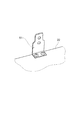
図10は、バスエプロンの取り付け状態を例示した模式的斜視図である。
床面材21の浴槽1側の外縁部21aは、バスエプロン9によって押圧してもよい。
図10に表したように、バスエプロン9を取り付ける際には、先ず、図10に表した矢印Dのように、バスエプロン9の上端部を浴槽1のフランジ部1aの裏面側に下から挿入する。続いて、図10に表した矢印Eのように、バスエプロン9の下端部を浴槽1側に押す。これにより、バスエプロン9を浴槽1の側面に取り付けることができる。
FIG. 10 is a schematic perspective view illustrating an attached state of the bus apron.
The
As shown in FIG. 10, when attaching the
バスエプロン9は、浴槽1のフランジ部1aと、床面材21と、の間に嵌め込まれる。この際、バスエプロン9によって、床面材21の浴槽1側の外縁部21aの溝部21bが押圧される。これにより、既存のバスエプロン9の取り付けと同時に床面材21の浮き上がりを抑制し、床面材21をしっかりと固定できることになる。
The
図11は、バスエプロンの取り付け構造の具体例を説明する模式的断面図である。
図11(a)に表した具体例では、バスエプロン9の下端9aによって直接的に床面材21の外縁部21aに設けられた溝部21bの底部を押圧している。
図11(b)に表した具体例では、バスエプロン9と床面材21との間にバネ性を有したクリップCPが設けられており、本実施形態で採用しているものである。このクリップCPは、通常、バスエプロン9の上下方向のガタ止め用として用いられるバネ部材であり、本発明における押圧部材に相当する。この例では、押圧部材であるクリップCPを介して本発明における壁面材としてのバスエプロン9の押圧力を床面材21の外縁部21aに設けられた溝部21bの底部に伝えている。
FIG. 11 is a schematic cross-sectional view for explaining a specific example of the attachment structure of the bath apron.
In the specific example shown in FIG. 11A, the bottom portion of the
In the specific example shown in FIG. 11B, a clip CP having a spring property is provided between the
即ち、本実施形態では、床面材21の浴槽1側をバスエプロン9で間接的に押圧し、その他の3辺を第1〜第3の壁パネル31〜33といった壁3によって直接的に押圧していることになる。したがって、床面材21の4辺に対応した外縁部21aを、そのために用意された特別な部材を用いることなく既存の部材だけで押さえ込むことによって、床面材21に定性的に発生する凹形状の全体的な変形を矯正して、床基材22に倣わせることが簡単かつ確実にできることになる。
That is, in this embodiment, the
次に、排水トラップによる床面材21の固定について説明する。
図12は、本発明における配管接続部材を構成する排水トラップの固定状態を例示した模式的断面図である。
Next, the fixing of the
FIG. 12 is a schematic cross-sectional view illustrating a fixed state of a drain trap that constitutes a pipe connection member in the present invention.
図12に表したように、排水トラップ400は、例えば支持フレーム232の第1フレーム232aにボルト等によって固定されており、トラップ本体410と、床面材21の排水口26を形成する排水凹部230を挟持する取付け用の雄ねじが設けられた取付フランジ(配管接続部材)420と、排水凹部230に挿入される封水筒430と、を備える。また、トラップ本体410には、取付フランジ420を螺結する雌ねじが設けられた開口部411と、浴槽1から排水された水を流入させる流入管接続部440と、室外の下水配管に連通する排水管接続部450とが設けられている。
As shown in FIG. 12, the
そして、取付フランジ420と、トラップ本体410との間にパッキン等を介して排水凹部230の底面部333を挟設させ、取付フランジ420をトラップ本体410に設けられた雌ねじに螺合させて締め付けることにより、床面材21の排水凹部230を排水トラップ400に水密的に連結することができる。
Then, the
本実施形態では、床基材22もボルト等によって支持フレーム232に固定されており、前述したように、その上面を洗い場床2の水平面の基準としている。そして、床面材21の下面(裏面)の排水凹部230近傍には、床基材22への取付け基準面213が形成されている。従って、床面材21の排水凹部230を排水トラップ400に水密的に連結する作業を行うことによって、床面材21の排水口26の部分を確実に固定できるだけでなく、取付け基準面213が床基材22の上面に押し付けられることによって、床面材21の排水勾配の起点となる排水凹部230の位置出しを同時に行うことができる。
In the present embodiment, the
なお、本実施形態では、排水凹部230は床面材21と一体で形成されているが、床面材21とは別体の部材で形成し、両者を別工程で一体化させた形態の床面材を床面材21として用いて本発明を適用することも可能である。その場合は、本発明を実施することによって生じる可能性のある新たな問題を容易に解決することが出来る。例えば、排水凹部230を別の材質で形成することにより、配管接続部材である排水トラップ400との接続部の強度をより強固なものにすることが容易に可能となる。
In this embodiment, the
また、本実施形態では、配管接続部材を配管接続機能に加えてトラップ機能を併せ持つものとしたが、配管接続機能のみを担う構成のものも本発明を適用することが出来る。 In this embodiment, the pipe connection member has a trap function in addition to the pipe connection function. However, the present invention can also be applied to a structure having only the pipe connection function.
次に、本実施形態にかかる浴室構造を備えた浴室ユニットの組立手順を説明する。
図13〜図16は、浴室ユニットの組立手順を説明する模式的斜視図である。
先ず、図13(a)に表したように、浴室ユニットの設置場所に、床保持部材23の支持脚231及び支持フレーム232を組み付ける。そして、支持フレーム232上に床基材22を載置して固定する。そして、その上面の水平確認を行い、必要な場合は作業口221hから支持脚231の高さ調整を行って水平出し作業を行う。次に、床基材22または支持フレーム232に壁面固定部材51を取り付ける。壁面固定部材51は、後の工程で壁面接続部材50を立設する位置に対応した箇所に取り付けられる。
Next, the assembly procedure of the bathroom unit provided with the bathroom structure according to the present embodiment will be described.
13 to 16 are schematic perspective views for explaining the assembly procedure of the bathroom unit.
First, as shown in FIG. 13A, the
次に、図13(b)に表したように、床基材22の上に、床面材21を載置する。本実施形態の床面材21は、前述したように、予めその表面にクッション材201及び表皮材202が貼り付けられた組品の床面部材として構成されている。このような床面材21を用いると、床基材22の上に床面材21を載置する作業だけで済むことになる。床面材21は発泡プラスチックによって形成されているため、製品の重量が軽く、設置場所への搬入や、支持フレーム232上への設置など、施工作業が行いやすい。
Next, as shown in FIG. 13B, the
なお、この載置作業は、壁面固定部材を取り付ける作業の前に行うことも可能である。その場合は前述したように、壁面固定部材51の代わりに床面材21を押圧出来る形状部を付加した形の壁面固定部材と、単品の床面材21と、を用いれば、床面材21を床基材22に仮固定することが出来る。そうすることで、その後の作業で床面材21の載置位置が狂うことを防止することが可能となる。
Note that this placing work can be performed before the work for attaching the wall surface fixing member. In this case, as described above, if a wall surface fixing member having a shape that can press the
続いて、排水管5に取り付けられた排水トラップ400と床面材21の排水口26とを取付フランジ(配管接続部材)420によって接続する。この作業により、床面材21の固定とともに、前述したように床面材21の裏面の排水口26近傍に設けられた取付け基準面213が床基材22の上面に押しつけられることによって、排水勾配の起点の位置出しも行われる。
Subsequently, the
この状態において、床面材21は、排水口の位置で排水トラップ400によって固定されているだけである。床面材21には、成形の際に変形(反り等)が生じている場合がある。したがって、床基材22に床面材21を載置し、排水トラップ400を取り付けた状態では、床面材21の外縁部21aに浮き上がりが生じている可能性がある。
In this state, the
次に、図14に表したように、支持脚6の上に浴槽1を取り付ける。また、浴槽1と洗い場床2との間に小パネル37を取り付ける。また、必要に応じて浴槽1の側面にバスエプロン9を取り付ける。バスエプロン9が取り付けられると、床面材21の浴槽1側の外縁部21aは、バスエプロン9またはバスエプロン9を固定するクリップCPによって押圧される。
Next, as shown in FIG. 14, the
次に、図15に表したように、洗い場床2の外周部2aに壁面接続部材50を取り付ける。壁面接続部材50は、予め取り付けてあった壁面固定部材51にボルトやビス等の締結手段で固定される。これにより、洗い場床2の外周部2aには、複数本の壁面接続部材50が立設されることになる。なお、壁面接続部材50を固定する際、壁面接続部材50の下端によって床面材21の外縁部21aを下方に押圧するようにしてもよい。
Next, as shown in FIG. 15, the wall
次に、図16に表したように、壁3を取り付ける。壁3のうち第1〜第5の壁パネル31〜35は、壁面接続部材50に嵌合することで固定される。また、浴槽1の洗い場床2とは反対側になる第6の壁パネル36は、第4の壁パネル34の一端と第5の壁パネル35一端との間に固定される。
Next, as shown in FIG. 16, the
このうち、第1〜第3の壁パネル31〜33を固定することにより、床面材21を上から押圧することができる。したがって、床面材21の外縁部21aを既存の第1〜第3の壁パネル31〜33の固定によって押圧し、床面材21の浮き上がりを矯正した状態で、床面材21を床基材22に密着固定できるようになる。
Among these, the
このあとは、浴槽・洗い場兼用水栓などの設備を装着し、必要な箇所にコーキング処理を施して浴室ユニットを完成させる。
なお、上記浴室ユニットの製造方法では、床面材21を取り付ける前に、壁面固定部材51を取り付けているが(図13(a)及び(b)参照)、床面材21を取り付けたあとで壁面固定部材51を取り付け、この取り付けの際に床面材21の外縁部21aを下方に押圧するようにしてもよい。
After this, equipment such as a bathtub / washing faucet will be installed, and the caulking process will be applied to the necessary places to complete the bathroom unit.
In addition, in the manufacturing method of the said bathroom unit, although the wall
その場合は前述したように、壁面固定部材51の代わりに床面材21を押圧出来る形状部を付加した形の壁面固定部材と、単品の床面材21と、を用いれば、床面材21を床基材22に仮固定することが出来る。そうすることで、その後の各種の作業によって床面材21の載置位置が狂うことを未然に防止することが可能となる。
In this case, as described above, if a wall surface fixing member having a shape that can press the
このような本実施形態によると、発泡プラスチックで成形した床面材21の成形ソリによる外縁部21aの浮き上がりが生じていても、壁3を装着するだけで簡単に無くすことができるようになる。
その結果、使用者は洗い場床2のガタつきを感じることなく、快適に浴室を利用することができる。
According to this embodiment, even if the
As a result, the user can comfortably use the bathroom without feeling the rattling of the
発泡プラスチックを床面材に用いた浴室構造において、以上説明したような本発明に係る浴室構造を適用すると、特別な部材や施工を必要とせず、容易かつ確実に床面材を床基材22に密着させることができる浴室構造が提供される。
When the bathroom structure according to the present invention as described above is applied to a bathroom structure using foamed plastic as a floor surface material, no special member or construction is required, and the
なお、本発明は上記の実施形態やその他の具体例の記述に限定されるものではない。前述の実施形態やその他の具体例に関して、当業者が適宜設計変更を加えたものも、本発明の特徴を備えている限り、本発明の範囲に包含される。
また、前述した実施形態やその他の具体例が備える各要素は、技術的に可能な限りにおいて組み合わせることができ、これらを組み合わせたものも本発明の特徴を含む限り本発明の範囲に包含される。
In addition, this invention is not limited to description of said embodiment and another specific example. As long as the features of the present invention are included in the above-described embodiments and other specific examples, those skilled in the art appropriately modify the design are included in the scope of the present invention.
In addition, the elements included in the above-described embodiments and other specific examples can be combined as long as technically possible, and combinations thereof are also included in the scope of the present invention as long as they include the features of the present invention. .
1…浴槽、2…洗い場床、2a…外周部、3…壁、5…排水管、6…支持脚、9…バスエプロン、21…床面材、21a…外縁部、21b…溝部、22…床基材、23…床保持部材、25…蓋、26…排水口、31…第1の壁パネル、31a…下端、32…第2の壁パネル、33…第3の壁パネル、34…第4の壁パネル、35…第5の壁パネル、36…第6の壁パネル、37…小パネル、50…壁面接続部材、51…壁面固定部材、201…クッション材、202…表皮材、211…床面材本体、211a…床面材ツバ、212…床面材枠、213…取付け基準面、221…蓋、221h…作業口、230…排水凹部、231…支持脚、232…支持フレーム、232a…第1フレーム、232b…第2フレーム、311…鋼板、311a…折り曲げ部分、333…底面部、400…排水トラップ、410…トラップ本体、411…開口部、420…取付フランジ、430…封水筒、440…流入管接続部、450…排水管接続部、501…折り返し部分、502…折り返し部分、CP…クリップ、CK…コーキング材、DR…ドア、PK…パッキン、S…浴室設置面
DESCRIPTION OF
Claims (4)
前記床保持部材の上に固定して設けられる床基材と、
前記床基材の上面に接して設けられ、発泡プラスチックで形成された床面材と、
前記浴室の立ち壁面を形成する壁面材と、を備え、
前記壁面材は、前記床面材の外縁部を前記床基材に向けて、線状に押圧することを特徴とする浴室構造。 A floor holding member installed on the bathroom installation surface;
A floor base material fixedly provided on the floor holding member;
A floor surface material provided in contact with the upper surface of the floor base material and formed of foamed plastic;
A wall material forming a standing wall surface of the bathroom,
The wall structure is a bathroom structure in which an outer edge portion of the floor surface material is pressed linearly toward the floor base material.
前記床保持部材の上に固定して設けられる床基材と、
フランジ状の外縁部を有して前記床基材の上面に接して設けられ、発泡プラスチックで形成された床面材と、
前記浴室の立ち壁面を形成する壁面材と、
前記壁面材の下端部と浴室床面との接続部の止水構造となる溝部を有して前記壁面材の下端部と前記床面材の外縁部との間に設けられた床面材枠と、を備え、
前記壁面材は、前記下端部が前記溝部に設けられた凹部に挿入されることによって、前記外縁部を前記床基材に向けて、線状に押圧することを特徴とする浴室構造。 A floor holding member installed on the bathroom installation surface;
A floor base material fixedly provided on the floor holding member;
A floor surface material having a flange-shaped outer edge portion and provided in contact with the upper surface of the floor base material, and formed of foamed plastic;
A wall material forming a standing wall surface of the bathroom;
A floor material frame provided between the lower edge of the wall material and the outer edge of the floor material, having a groove that forms a water stop structure for the connection between the lower edge of the wall material and the bathroom floor. And comprising
The said wall surface material presses the said outer edge part linearly toward the said floor base material by inserting the said lower end part in the recessed part provided in the said groove part, The bathroom structure characterized by the above-mentioned.
前記複数の壁面材どうしを連接する壁面接続部材と、
前記壁面接続部材を前記床基材または前記床保持部材に固定する壁面固定部材と、
をさらに備え、
前記壁面接続部材及び前記壁面固定部材のうち少なくとも一方で前記外縁部を下方に押圧することを特徴とする請求項1または2に記載の浴室構造。 A plurality of the wall materials;
A wall surface connecting member connecting the plurality of wall surface materials;
A wall surface fixing member for fixing the wall surface connecting member to the floor base material or the floor holding member;
Further comprising
3. The bathroom structure according to claim 1, wherein at least one of the wall surface connecting member and the wall surface fixing member presses the outer edge portion downward. 4.
前記配管接続部材を前記床基材または前記床保持部材に対して固定するとともに、前記配管接続部材を前記排水口に取り付けることによって、前記床面材の前記排水口を前記床基材に対して固定したことを特徴とする請求項1〜3のいずれか1つに記載の浴室構造。 A pipe connection member for connecting a drain outlet provided in the floor surface material and a drain pipe for discharging water used in the bathroom;
While fixing the said piping connection member with respect to the said floor base material or the said floor holding member, attaching the said piping connection member to the said drain outlet, the said drain outlet of the said floor surface material with respect to the said floor base material The bathroom structure according to any one of claims 1 to 3, wherein the bathroom structure is fixed.
Priority Applications (1)
| Application Number | Priority Date | Filing Date | Title |
|---|---|---|---|
| JP2010266818A JP5720877B2 (en) | 2010-11-30 | 2010-11-30 | Bathroom structure |
Applications Claiming Priority (1)
| Application Number | Priority Date | Filing Date | Title |
|---|---|---|---|
| JP2010266818A JP5720877B2 (en) | 2010-11-30 | 2010-11-30 | Bathroom structure |
Publications (2)
| Publication Number | Publication Date |
|---|---|
| JP2012117257A true JP2012117257A (en) | 2012-06-21 |
| JP5720877B2 JP5720877B2 (en) | 2015-05-20 |
Family
ID=46500411
Family Applications (1)
| Application Number | Title | Priority Date | Filing Date |
|---|---|---|---|
| JP2010266818A Active JP5720877B2 (en) | 2010-11-30 | 2010-11-30 | Bathroom structure |
Country Status (1)
| Country | Link |
|---|---|
| JP (1) | JP5720877B2 (en) |
Cited By (16)
| Publication number | Priority date | Publication date | Assignee | Title |
|---|---|---|---|---|
| JP2014132141A (en) * | 2013-01-07 | 2014-07-17 | Toclas Corp | Support structure for wall panel |
| JP2014181469A (en) * | 2013-03-18 | 2014-09-29 | Toto Ltd | Bathroom structure |
| JP2015166540A (en) * | 2014-03-04 | 2015-09-24 | Toto株式会社 | bathroom structure |
| JP2015190286A (en) * | 2014-03-31 | 2015-11-02 | Toto株式会社 | Body wash floor of bath room |
| JP2015190287A (en) * | 2014-03-31 | 2015-11-02 | Toto株式会社 | Body wash floor of bath room |
| JP2015190288A (en) * | 2014-03-31 | 2015-11-02 | Toto株式会社 | Body wash floor of bath room |
| JP2015190289A (en) * | 2014-03-31 | 2015-11-02 | Toto株式会社 | Body wash floor of bath room |
| JP2015194010A (en) * | 2014-03-31 | 2015-11-05 | Toto株式会社 | Wash place floor of bathroom |
| JP2015194011A (en) * | 2014-03-31 | 2015-11-05 | Toto株式会社 | Wash place floor of bathroom |
| JP2016050431A (en) * | 2014-08-29 | 2016-04-11 | Toto株式会社 | Seal method between floor and wall of wash place in bathroom |
| JP2016065391A (en) * | 2014-09-25 | 2016-04-28 | Toto株式会社 | Wash place floor of bathroom |
| JP7353587B2 (en) | 2019-12-04 | 2023-10-02 | Toto株式会社 | Unit room for plumbing equipment |
| JP7357854B2 (en) | 2019-12-04 | 2023-10-10 | Toto株式会社 | Unit room for plumbing equipment |
| JP7399386B2 (en) | 2019-12-04 | 2023-12-18 | Toto株式会社 | Unit room for plumbing equipment |
| JP7399385B2 (en) | 2019-12-04 | 2023-12-18 | Toto株式会社 | Unit room for plumbing equipment |
| JP7421723B2 (en) | 2019-12-04 | 2024-01-25 | Toto株式会社 | Unit room for plumbing equipment |
Citations (3)
| Publication number | Priority date | Publication date | Assignee | Title |
|---|---|---|---|---|
| JPH11343650A (en) * | 1998-06-02 | 1999-12-14 | Toto Ltd | Waterproof floor pan for bathroom |
| JP2008121352A (en) * | 2006-11-14 | 2008-05-29 | Toto Ltd | Structure for mounting bathroom unit component on floor of washing place |
| JP2009144404A (en) * | 2007-12-13 | 2009-07-02 | Toto Ltd | Wash place floor for bathroom |
-
2010
- 2010-11-30 JP JP2010266818A patent/JP5720877B2/en active Active
Patent Citations (3)
| Publication number | Priority date | Publication date | Assignee | Title |
|---|---|---|---|---|
| JPH11343650A (en) * | 1998-06-02 | 1999-12-14 | Toto Ltd | Waterproof floor pan for bathroom |
| JP2008121352A (en) * | 2006-11-14 | 2008-05-29 | Toto Ltd | Structure for mounting bathroom unit component on floor of washing place |
| JP2009144404A (en) * | 2007-12-13 | 2009-07-02 | Toto Ltd | Wash place floor for bathroom |
Cited By (16)
| Publication number | Priority date | Publication date | Assignee | Title |
|---|---|---|---|---|
| JP2014132141A (en) * | 2013-01-07 | 2014-07-17 | Toclas Corp | Support structure for wall panel |
| JP2014181469A (en) * | 2013-03-18 | 2014-09-29 | Toto Ltd | Bathroom structure |
| JP2015166540A (en) * | 2014-03-04 | 2015-09-24 | Toto株式会社 | bathroom structure |
| JP2015190286A (en) * | 2014-03-31 | 2015-11-02 | Toto株式会社 | Body wash floor of bath room |
| JP2015190287A (en) * | 2014-03-31 | 2015-11-02 | Toto株式会社 | Body wash floor of bath room |
| JP2015190288A (en) * | 2014-03-31 | 2015-11-02 | Toto株式会社 | Body wash floor of bath room |
| JP2015190289A (en) * | 2014-03-31 | 2015-11-02 | Toto株式会社 | Body wash floor of bath room |
| JP2015194010A (en) * | 2014-03-31 | 2015-11-05 | Toto株式会社 | Wash place floor of bathroom |
| JP2015194011A (en) * | 2014-03-31 | 2015-11-05 | Toto株式会社 | Wash place floor of bathroom |
| JP2016050431A (en) * | 2014-08-29 | 2016-04-11 | Toto株式会社 | Seal method between floor and wall of wash place in bathroom |
| JP2016065391A (en) * | 2014-09-25 | 2016-04-28 | Toto株式会社 | Wash place floor of bathroom |
| JP7353587B2 (en) | 2019-12-04 | 2023-10-02 | Toto株式会社 | Unit room for plumbing equipment |
| JP7357854B2 (en) | 2019-12-04 | 2023-10-10 | Toto株式会社 | Unit room for plumbing equipment |
| JP7399386B2 (en) | 2019-12-04 | 2023-12-18 | Toto株式会社 | Unit room for plumbing equipment |
| JP7399385B2 (en) | 2019-12-04 | 2023-12-18 | Toto株式会社 | Unit room for plumbing equipment |
| JP7421723B2 (en) | 2019-12-04 | 2024-01-25 | Toto株式会社 | Unit room for plumbing equipment |
Also Published As
| Publication number | Publication date |
|---|---|
| JP5720877B2 (en) | 2015-05-20 |
Similar Documents
| Publication | Publication Date | Title |
|---|---|---|
| JP5720877B2 (en) | Bathroom structure | |
| JP6355064B2 (en) | Bathroom structure | |
| JP2008025122A (en) | Floor equipped with waterproof function | |
| JP2012197608A (en) | Shower room floor structure | |
| JP6011991B2 (en) | Bathroom structure | |
| JP7016475B2 (en) | Mounting structure of bathroom wall members | |
| JP6614487B2 (en) | bathroom | |
| JP5126446B1 (en) | How to assemble bathroom washroom | |
| JP5660318B2 (en) | Washroom floor | |
| JP5831812B2 (en) | Wash floor bread | |
| JP6714811B2 (en) | Construction method of joint material of bathroom | |
| JP5263554B2 (en) | Washroom floor | |
| JP6771736B2 (en) | Skin material and washroom floor | |
| JP6889871B2 (en) | How to assemble a bathtub, bathroom, and bathroom | |
| JP5076254B1 (en) | Bathroom structure | |
| JP6692521B2 (en) | How to construct a dry joint in a bathroom | |
| JP6780236B2 (en) | bathroom | |
| JP6809593B2 (en) | Skin material, washroom floor, and bathtub | |
| JP2020112028A (en) | Washroom floor, wall, bathroom and method of assembling bathroom | |
| JP2010112056A (en) | Wash place floor for bathroom | |
| JP6714812B2 (en) | bathroom | |
| JP7009862B2 (en) | Mounting structure of bathroom wall members | |
| JP5696975B2 (en) | Washing floor surface material | |
| JP2019094762A (en) | Bathroom floor structure | |
| JP2020141966A (en) | Bathroom and bathtub |
Legal Events
| Date | Code | Title | Description |
|---|---|---|---|
| A621 | Written request for application examination |
Free format text: JAPANESE INTERMEDIATE CODE: A621 Effective date: 20131107 |
|
| A977 | Report on retrieval |
Free format text: JAPANESE INTERMEDIATE CODE: A971007 Effective date: 20140612 |
|
| A131 | Notification of reasons for refusal |
Free format text: JAPANESE INTERMEDIATE CODE: A131 Effective date: 20140620 |
|
| A521 | Written amendment |
Free format text: JAPANESE INTERMEDIATE CODE: A523 Effective date: 20140818 |
|
| TRDD | Decision of grant or rejection written | ||
| A01 | Written decision to grant a patent or to grant a registration (utility model) |
Free format text: JAPANESE INTERMEDIATE CODE: A01 Effective date: 20150225 |
|
| A61 | First payment of annual fees (during grant procedure) |
Free format text: JAPANESE INTERMEDIATE CODE: A61 Effective date: 20150310 |
|
| R150 | Certificate of patent or registration of utility model |
Ref document number: 5720877 Country of ref document: JP Free format text: JAPANESE INTERMEDIATE CODE: R150 |