JP2012115780A - Co2 recovery system - Google Patents
Co2 recovery system Download PDFInfo
- Publication number
- JP2012115780A JP2012115780A JP2010268865A JP2010268865A JP2012115780A JP 2012115780 A JP2012115780 A JP 2012115780A JP 2010268865 A JP2010268865 A JP 2010268865A JP 2010268865 A JP2010268865 A JP 2010268865A JP 2012115780 A JP2012115780 A JP 2012115780A
- Authority
- JP
- Japan
- Prior art keywords
- lean solution
- solution
- lean
- absorption liquid
- regeneration tower
- Prior art date
- Legal status (The legal status is an assumption and is not a legal conclusion. Google has not performed a legal analysis and makes no representation as to the accuracy of the status listed.)
- Granted
Links
Images


Classifications
-
- B—PERFORMING OPERATIONS; TRANSPORTING
- B01—PHYSICAL OR CHEMICAL PROCESSES OR APPARATUS IN GENERAL
- B01D—SEPARATION
- B01D53/00—Separation of gases or vapours; Recovering vapours of volatile solvents from gases; Chemical or biological purification of waste gases, e.g. engine exhaust gases, smoke, fumes, flue gases, aerosols
- B01D53/14—Separation of gases or vapours; Recovering vapours of volatile solvents from gases; Chemical or biological purification of waste gases, e.g. engine exhaust gases, smoke, fumes, flue gases, aerosols by absorption
- B01D53/1425—Regeneration of liquid absorbents
-
- B—PERFORMING OPERATIONS; TRANSPORTING
- B01—PHYSICAL OR CHEMICAL PROCESSES OR APPARATUS IN GENERAL
- B01D—SEPARATION
- B01D53/00—Separation of gases or vapours; Recovering vapours of volatile solvents from gases; Chemical or biological purification of waste gases, e.g. engine exhaust gases, smoke, fumes, flue gases, aerosols
- B01D53/14—Separation of gases or vapours; Recovering vapours of volatile solvents from gases; Chemical or biological purification of waste gases, e.g. engine exhaust gases, smoke, fumes, flue gases, aerosols by absorption
- B01D53/1456—Removing acid components
- B01D53/1475—Removing carbon dioxide
-
- B—PERFORMING OPERATIONS; TRANSPORTING
- B01—PHYSICAL OR CHEMICAL PROCESSES OR APPARATUS IN GENERAL
- B01D—SEPARATION
- B01D2252/00—Absorbents, i.e. solvents and liquid materials for gas absorption
- B01D2252/20—Organic absorbents
- B01D2252/204—Amines
-
- B—PERFORMING OPERATIONS; TRANSPORTING
- B01—PHYSICAL OR CHEMICAL PROCESSES OR APPARATUS IN GENERAL
- B01D—SEPARATION
- B01D2258/00—Sources of waste gases
- B01D2258/02—Other waste gases
- B01D2258/0283—Flue gases
-
- B—PERFORMING OPERATIONS; TRANSPORTING
- B01—PHYSICAL OR CHEMICAL PROCESSES OR APPARATUS IN GENERAL
- B01D—SEPARATION
- B01D2259/00—Type of treatment
- B01D2259/65—Employing advanced heat integration, e.g. Pinch technology
-
- Y—GENERAL TAGGING OF NEW TECHNOLOGICAL DEVELOPMENTS; GENERAL TAGGING OF CROSS-SECTIONAL TECHNOLOGIES SPANNING OVER SEVERAL SECTIONS OF THE IPC; TECHNICAL SUBJECTS COVERED BY FORMER USPC CROSS-REFERENCE ART COLLECTIONS [XRACs] AND DIGESTS
- Y02—TECHNOLOGIES OR APPLICATIONS FOR MITIGATION OR ADAPTATION AGAINST CLIMATE CHANGE
- Y02C—CAPTURE, STORAGE, SEQUESTRATION OR DISPOSAL OF GREENHOUSE GASES [GHG]
- Y02C20/00—Capture or disposal of greenhouse gases
- Y02C20/40—Capture or disposal of greenhouse gases of CO2
-
- Y—GENERAL TAGGING OF NEW TECHNOLOGICAL DEVELOPMENTS; GENERAL TAGGING OF CROSS-SECTIONAL TECHNOLOGIES SPANNING OVER SEVERAL SECTIONS OF THE IPC; TECHNICAL SUBJECTS COVERED BY FORMER USPC CROSS-REFERENCE ART COLLECTIONS [XRACs] AND DIGESTS
- Y02—TECHNOLOGIES OR APPLICATIONS FOR MITIGATION OR ADAPTATION AGAINST CLIMATE CHANGE
- Y02E—REDUCTION OF GREENHOUSE GAS [GHG] EMISSIONS, RELATED TO ENERGY GENERATION, TRANSMISSION OR DISTRIBUTION
- Y02E20/00—Combustion technologies with mitigation potential
- Y02E20/32—Direct CO2 mitigation
Abstract
Description
本発明は、排ガス中に含まれるCO2を除去する吸収液を用いたCO2回収システムに関する。 The present invention relates to a CO 2 recovery system using an absorption liquid that removes CO 2 contained in exhaust gas.
近年、地球の温暖化現象の原因の一つとして、CO2による温室効果が指摘され、地球環境を守る上で国際的にもその対策が急務となってきた。CO2の発生源としては化石燃料を燃焼させるあらゆる人間の活動分野に及び、その排出抑制への要求が一層強まる傾向にある。これに伴い尿素等の原料(化学用途)、原油増産、及び地球温暖化対策として、大量の化石燃料を使用する火力発電所などの動力発生設備を対象に、ボイラの燃焼排ガスをアミン系CO2吸収液と接触させ、燃焼排ガス中のCO2を除去、回収する方法及び回収されたCO2を大気へ放出することなく貯蔵する方法が精力的に研究されている。 In recent years, the greenhouse effect due to CO 2 has been pointed out as one of the causes of global warming, and countermeasures have become urgent internationally to protect the global environment. The source of CO 2 extends to all human activity fields that burn fossil fuels, and there is a tendency for the demand for emission control to become stronger. Along with this, as a raw material such as urea (chemical use), crude oil production increase, and global warming countermeasures, boiler combustion exhaust gas is converted to amine-based CO 2 for power generation facilities such as thermal power plants that use large amounts of fossil fuels. A method of removing and recovering CO 2 in combustion exhaust gas by bringing it into contact with an absorbing solution and a method of storing the recovered CO 2 without releasing it to the atmosphere have been energetically studied.
大量の燃焼排ガス中のCO2を回収・貯蔵する実用的な方法として、例えばアミン水溶液等のCO2吸収液と接触させる化学吸収法がある。前記のようなCO2吸収液を用い、燃焼排ガスからCO2を除去・回収する工程としては、CO2吸収塔において燃焼排ガスとCO2吸収液とを接触させる工程、CO2を吸収した吸収液を吸収液再生塔において加熱し、CO2を遊離させると共に吸収液を再生して再びCO2吸収塔に循環して再使用するものが採用されている(特許文献1)。 As a practical method for recovering and storing CO 2 in a large amount of combustion exhaust gas, there is a chemical absorption method in which it is brought into contact with a CO 2 absorbing solution such as an aqueous amine solution. The step of removing and recovering CO 2 from the combustion exhaust gas using the CO 2 absorption liquid as described above includes a step of bringing the combustion exhaust gas and the CO 2 absorption liquid into contact with each other in a CO 2 absorption tower, and an absorption liquid that has absorbed CO 2. Is used in the absorption liquid regeneration tower to liberate CO 2 and regenerate the absorption liquid, and circulate again to the CO 2 absorption tower for reuse (Patent Document 1).
この従来の化学吸収法によるCO2回収装置の運転は、吸収液再生塔において高温のスチーム等でアミン水溶液とCO2とを分離させているが、このスチーム(エネルギー)の消費を最小化させる必要があった。そのため、これまで、二種類以上の異なるCO2吸収液を混合して用いる方法(特許文献2、3)、CO2吸収液を送給するプロセスを改良する方法が検討されていた(特許文献4)。
In the operation of this conventional chemical absorption method CO 2 recovery device, the amine aqueous solution and CO 2 are separated by high-temperature steam or the like in the absorption liquid regeneration tower, but it is necessary to minimize the consumption of steam (energy). was there. For this reason, methods for mixing and using two or more different CO 2 absorbents (
しかしながら、上述のCO2吸収液を用いて燃焼排ガスのようなCO2を含有する排ガスからCO2を吸収除去・回収するシステムにおいては、燃焼設備に付加して設置されるため、その操業費用もできるだけ低減させる必要がある。特に吸収液を再生する吸収液再生塔においては、多量の熱エネルギーを消費するので、スチームのエネルギーをより軽減し、可能な限り省エネルギー化が可能なプロセスとする必要がある。 However, in the system for absorbing and removing CO 2 from the exhaust gas containing CO 2 such as combustion exhaust gas using the above-mentioned CO 2 absorbent, it is installed in addition to the combustion equipment, so its operating cost is also It is necessary to reduce as much as possible. In particular, an absorption liquid regeneration tower that regenerates the absorption liquid consumes a large amount of heat energy, and thus it is necessary to reduce the steam energy and to make the process as energy-saving as possible.
また、従来のCO2回収システムが大型化し、CO2回収量が1日当たり例えば1000t以上の処理量となると、再生工程において要するリボイラの熱エネルギーも多量に消費することになるため、スチームのエネルギーをより軽減し、省エネルギー化を図る必要がある。 In addition, if the conventional CO 2 recovery system becomes large and the CO 2 recovery amount reaches a processing amount of 1000 t or more per day, for example, the reboiler's thermal energy required in the regeneration process will be consumed in large quantities. It is necessary to further reduce and save energy.
本発明は、前記問題に鑑み、リボイラの熱エネルギーをより軽減し、省エネルギー化を図るCO2回収システムを提供することを課題とする。 In view of the above problems, an object of the present invention is to provide a CO 2 recovery system that further reduces the thermal energy of the reboiler and saves energy.
上述した課題を解決するための本発明の第1の発明は、冷却されたCO2を含有する排ガスとCO2を吸収するCO2吸収液とを接触させて前記排ガスからCO2を除去するCO2吸収塔と、CO2を吸収したCO2吸収液からCO2を放出させて吸収液を再生する第1の吸収液再生塔と、第1の吸収液再生塔から排出された第1リーン溶液から残存するCO2を放出させて吸収液を再生する第2の吸収液再生塔と、第2の吸収液再生塔から排出された第2リーン溶液をフラッシュさせるフラッシュドラムと、該フラッシュドラムで発生した蒸気を第1の吸収液再生塔に投入することを特徴とするCO2回収システムにある。 The first aspect of the present invention to solve the problems described above is brought into contact with CO 2 absorbing liquid to absorb the exhaust gas and CO 2 containing the cooled CO 2 removing CO 2 from the exhaust gas CO and 2 absorber, the first absorbent regenerator to regenerate the absorbing solution to release CO 2 from the CO 2 absorbent having absorbed CO 2, the first lean solution discharged from the first absorbent regenerator A second absorbing liquid regeneration tower that regenerates the absorbing liquid by releasing the remaining CO 2 from the liquid, a flash drum that flushes the second lean solution discharged from the second absorbing liquid regeneration tower, and generated in the flash drum The CO 2 recovery system is characterized in that the steam that has been put into the first absorption liquid regeneration tower.
第2の発明は、第1の発明において、第1のリーン溶液と前記フラッシュドラムでフラッシュさせた第3のリーン溶液とを熱交換するリーン・リーン溶液熱交換器を有することを特徴とするCO2回収システムにある。 A second invention includes a lean-lean solution heat exchanger for exchanging heat between the first lean solution and the third lean solution flashed by the flash drum in the first invention. 2 in the collection system.
第3の発明は、第1の発明において、第1の吸収液再生塔の塔内部を鉛直軸方向の中間部分で、セミリーン溶液を抜き出すポートと、セミリーン溶液が抜き出され、抜き出しポートより底部側の戻し入れポートに戻しいれる循環ラインと、循環ラインに介装され、フラッシュドラムでフラッシュさせた第3のリーン溶液とセミリーン溶液とが熱交換するセミリーン・リーン溶液熱交換器と、を有することを特徴とするCO2回収システムにある。 According to a third invention, in the first invention, the semi-lean solution is extracted at the middle portion in the vertical axis direction inside the first absorption liquid regeneration tower, the semi-lean solution is extracted, and the bottom side from the extraction port. And a semi-lean / lean solution heat exchanger that is interposed in the circulation line and exchanges heat between the third lean solution flushed with the flash drum and the semi-lean solution. It is in the characteristic CO 2 capture system.
第4の発明は、第1の発明において、第1のリーン溶液と、フラッシュドラムでフラッシュさせた第3のリーン溶液とが熱交換するリーン・リーン溶液熱交換器と、第1の吸収液再生塔の塔内部を鉛直軸方向の中間部分で、セミリーン溶液を抜き出すポートと、セミリーン溶液が抜き出され、抜き出しポートより底部側の戻し入れポートに戻しいれる循環ラインと、循環ラインに介装され、前記第3のリーン溶液とセミリーン溶液とが熱交換するセミリーン・リーン溶液熱交換器と、を有することを特徴とするCO2回収システムにある。 According to a fourth invention, in the first invention, a lean / lean solution heat exchanger in which heat exchange is performed between the first lean solution and the third lean solution flushed by the flash drum, and the first absorbent regeneration In the middle part of the tower in the vertical axis direction, a port for extracting the semi-lean solution, a circulation line from which the semi-lean solution is extracted and returned to the return port on the bottom side from the extraction port, and a circulation line, A CO 2 recovery system comprising: a semi-lean / lean solution heat exchanger that exchanges heat between the third lean solution and the semi-lean solution.
第5の発明は、第1乃至4のいずれか一つの発明において、CO2を含有する排ガスを冷却水によって冷却する冷却塔を有することを特徴とするCO2回収システムにある。 A fifth invention is the CO 2 recovery system according to any one of the first to fourth inventions, further comprising a cooling tower that cools the exhaust gas containing CO 2 with cooling water.
本発明によれば、CO2を吸収したCO2吸収液(リッチ溶液)からCO2を放出させて吸収液を再生する第1の吸収液再生塔及び第2の吸収液再生塔とを有し、第2の吸収液再生塔出口の第2リーン溶液を減圧フラッシュさせ、そのフラッシュ蒸気を第1の吸収液再生塔に投入することで、リボイラの熱エネルギーをより軽減し、省エネルギー化を図ることができる。 According to the present invention, and a first absorption liquid regenerator and second absorption liquid regenerator CO 2 absorbent that has absorbed CO 2 by releasing CO 2 from (rich solution) to play absorbing liquid The second lean solution at the outlet of the second absorption liquid regeneration tower is flushed under reduced pressure, and the flash vapor is injected into the first absorption liquid regeneration tower, thereby reducing the reboiler thermal energy and saving energy. Can do.
以下、この発明につき図面を参照しつつ詳細に説明する。なお、この実施例によりこの発明が限定されるものではない。また、下記実施例における構成要素には、当業者が容易に想定できるもの、あるいは実質的に同一のものが含まれる。 Hereinafter, the present invention will be described in detail with reference to the drawings. Note that the present invention is not limited to the embodiments. In addition, constituent elements in the following embodiments include those that can be easily assumed by those skilled in the art or those that are substantially the same.
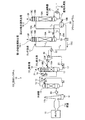
本発明による実施例に係るCO2回収システムについて、図面を参照して説明する。図1は、CO2回収システムの概略図である。
図1に示すように、CO2回収システム10は、例えばボイラ11やガスタービン等の産業設備から排出されたCO2を含有する排ガス12を冷却水13によって冷却する冷却塔14と、冷却されたCO2を含有する排ガス12とCO2を吸収するCO2吸収液15とを接触させて前記排ガス12からCO2を除去するCO2吸収塔16と、CO2を吸収したCO2吸収液(リッチ溶液)17からCO2を放出させて第1のリーン吸収液(第1のリーン溶液)15Aを再生する第1の吸収液再生塔18−1及び第2のリーン吸収液(第2のリーン溶液)15Bを再生する第2の吸収液再生塔18−2とを有する。
このシステムでは、第1の吸収液再生塔18−1でCO2を除去した第1のリーン溶液15Aは、第2の吸収液再生塔18−2に送られ、ここで、再度CO2を除去して第2のリーン溶液15Bとし、その後、フラッシュドラム50で減圧フラッシュさせることで、気体側の水蒸気52を第1の吸収液再生塔18−1の熱源として利用し、フラッシュドラム50でフラッシュさせた液体側は、第3のリーン吸収液(第3のリーン溶液)15Cとし、その後冷却されて、CO2吸収塔16側に送られ再度排ガス12中のCO2を吸収するCO2吸収液15として利用する。
A CO 2 recovery system according to an embodiment of the present invention will be described with reference to the drawings. FIG. 1 is a schematic view of a CO 2 recovery system.
As shown in FIG. 1, the CO 2 recovery system 10 is cooled by a
In this system, the first
このCO2回収システムを用いたCO2回収方法では、まずCO2を含有する排ガス12は、排ガス送風機20により昇圧された後、冷却塔14に送られ、ここで冷却水13により冷却され、CO2吸収塔16に送られる。
CO2吸収塔16は、塔内部に充填部16A、16Bが設けられ、塔下部に配設される充填部16Aで排ガス12とCO2吸収液15との対向接触効率を向上させている。塔上部に配設される充填部16Bでは、排ガス12と冷却水19との対向接触効率を向上させている。
In the CO 2 recovery method using this CO 2 recovery system, the
The CO 2 absorption tower 16 is provided with
前記CO2吸収塔16において、排ガス12は例えばアミン系の吸収液15と交向流接触し、排ガス12中のCO2は、化学反応(R−NH2+H2O+CO2→R−NH3HCO3)によりCO2吸収液15に吸収され、CO2が除去された浄化排ガス21は系外に放出される。CO2を吸収したCO2吸収液17は「リッチ溶液」とも呼称される。このリッチ溶液17は、リッチソルベントポンプ22により昇圧され、リッチ・リーン溶液熱交換器23において、再生された第3のリーン吸収液15Cとの熱交換により加熱され、その後、第1の吸収液再生塔18−1に供給される。
リッチ溶液17は、CO2吸収塔16からリッチ溶液供給ラインL1により第1の吸収液再生塔18−1に供給されている。また、第3のリーン溶液15Cは、第2の吸収液再生塔18−2からフラッシュドラム50でフラッシュさせた後のリーン溶液供給ラインL2によりリーン溶液ポンプ53を介してCO2吸収塔16に供給されている。リッチ・リーン溶液熱交換器23は両者の交差点に設けられている。
なお、フラッシュドラムでフラッシュさせた第3のリーン溶液15Cは、リーンソルベントクーラ31により冷却され、CO2吸収液15としてCO2吸収塔16内に導入されている。
In the CO 2 absorption tower 16, the
The
The third
図2は、第1の吸収液再生塔18−1及び第2の吸収液再生塔18−2の要部を示す図である。
リッチ・リーン溶液熱交換器23により熱交換されたリッチ溶液17は、第1の吸収液再生塔18−1の上部から塔内部に導入され、第1の吸収液再生塔18−1内を流下する際に、水蒸気52による吸熱反応を生じて、大部分のCO2を放出し、再生される。第1の吸収液再生塔18−1内で一部または大部分のCO2を放出した吸収液は「セミリーン溶液」と呼称される。このセミリーン溶液は、第1の吸収液再生塔18−1の下部に至る頃には、大部分のCO2が除去された第1のリーン溶液15Aとなる。
FIG. 2 is a diagram showing a main part of the first absorption liquid regeneration tower 18-1 and the second absorption liquid regeneration tower 18-2.
The
ついで、第1の吸収液15Aは、第2の吸収液再生塔18−2に導入され、第2の吸収液再生塔18−2内を流下する際に、水蒸気による吸熱反応を生じて、残存するほとんどのCO2を放出し、再生される。CO2が除去されることにより再生されたこの第2のリーン溶液15Bは再生過熱器24で飽和水蒸気25により間接的に過熱され、塔内に水蒸気を供給している。
Next, the first absorbing
また、第1及び第2の吸収液再生塔18−1、18−2においては、共に各々の塔頂部からは塔内においてリッチ溶液17及びセミリーン溶液から放出された水蒸気を伴ったCO2ガス26が導出され、コンデンサ27により水蒸気が凝縮され、分離ドラム28にて水26bが分離され、CO2ガス26aが系外に放出されて回収される。分離ドラム28にて分離された水26bは凝縮水循環ポンプ29にて吸収液再生塔18の上部に供給される。
In each of the first and second absorbing liquid regeneration towers 18-1 and 18-2, the CO 2 gas 26 accompanied by water vapor released from the
また、第2の吸収液再生塔18−2で再生された第2リーン溶液15Bは、フラッシュドラム50に導入され、フラッシュすることで、リーン溶液15は100℃となり、リッチ・リーン溶液熱交換器23に導入される第3のリーン溶液15Cの温度は100℃以下となり、50℃でリッチ・リーン溶液熱交換器23に導入され、熱交換された後のリッチ溶液17の温度は95℃となる。図2中、符号51は減圧弁である。
In addition, the second
フラッシュドラムでフラッシュさせた第3のリーン溶液15Cは、前記リッチ・リーン溶液熱交換器23にて前記リッチ溶液17により冷却され、つづいてリーンソルベントポンプ30にて昇圧され、さらにリーンソルベントクーラ31にて冷却された後、再びCO2吸収塔16に供給され、CO2吸収液15として再利用される。
The third
なお、図1中、符号11aはボイラ11やガスタービン等の産業設備の煙道であり、11bは煙突、18A、18Bは充填部、18Cはミストエリミネータである。前記CO2回収システムは、既設の排ガス12源からCO2を回収するために後付で設けられる場合と、新設排ガス12源に同時付設される場合とがある。煙突11bには開閉可能な扉を設置し、CO2回収システムの運転時は閉止する。また排ガス12源は稼動しているが、CO2回収システムの運転を停止した際は開放するように設定する。
In FIG. 1,
本実施例では、第1及び第2の吸収液再生塔18−1、18−2を有すると共に、第2の吸収液再生塔18−2から排出された第2リーン溶液15Bの熱を回収するリーン溶液降温手段としてフラッシュドラム50を設けており、第2のリーン溶液15Bの熱を有効利用するようにしている。
In the present embodiment, the first and second absorption liquid regeneration towers 18-1 and 18-2 are included, and the heat of the second
第1のリーン15Aは、第1の吸収液再生塔18−1から第1のリーン溶液供給ラインL3により第2の吸収液再生塔18−2に供給されている。また、第2のリーン溶液15Bは第2の吸収液再生塔18−2から第2のリーン溶液供給ラインL4によりフラッシュドラム50に供給されている。
The first lean 15A is supplied by the first lean-solution supply line L 3 from the first absorbent regenerator 18-1 to the second absorbent regenerator 18-2. The second
フラッシュドラム50からフラッシュされた水蒸気52は、フラッシュドラム50から伸びる水蒸気供給ラインL5により第1の吸収液再生塔18−1に供給されている。
一方の減圧された第3のリーン溶液15Cは、フラッシュドラム50から伸びるリーン溶液供給ラインL2によりCO2吸収塔16に供給されている。
The
One decompressed third
すなわち、第2のリーン溶液15Bは第2の吸収液再生塔18−2で飽和水蒸気25により間接的に加熱された水蒸気により過熱されているので、120℃程度で系外に排出され、フラッシュドラム50に導入される。
この際、フラッシュドラム50によりその熱を回収し、第2のリーン溶液15Bの温度を降下させ、第3のリーン溶液15Cとすることで、リッチ・リーン溶液熱交換器23の熱交換容量を小さくすることができる。
That is, since the second
At this time, the heat is recovered by the
ここで、第2の吸収液再生塔18−2から排出される第2のリーン溶液15Bの温度T1が例えば120℃の場合、フラッシュドラム50で第2のリーン溶液15Bをフラッシュすることで、フラッシュの後の第3のリーン溶液15Cの温度T2は100℃程度となる。
Here, when the temperature T 1 of the second
例えばリッチ溶液17の温度T3が50℃の場合、リッチ・リーン溶液熱交換器23に導入される第3のリーン溶液15Cの温度T2が100℃以下で熱交換されるので、熱交換後のリッチ溶液17の温度T4は95℃となる。また、第3のリーン溶液15Cの熱交換後の温度T5は55℃に低下する。なお、水蒸気として第1の吸収液再生塔18−1から外部に排出する温度T6は82.5℃であり、第2の吸収液再生塔18−2から外部に排出する温度T7は85℃である。なお、第1の吸収液再生塔18−1から第2の吸収液再生塔18−2に供給される第1のリーン溶液15Aの温度T8は95℃である。
ここで、吸収液再生塔18の塔内は0.9kg/cm2Gである。
For example, when the temperature T 3 of the
Here, the inside of the absorption liquid regeneration tower 18 is 0.9 kg / cm 2 G.
よって、第1の吸収液再生塔18−1に導入されるリッチ溶液17の温度が従来よりも低いので、第1の吸収液再生塔18−1でのリボイラ熱量の低下を図ることができる。
ここで、第1及び第2の吸収液再生塔18−1、18−2のリボイラ熱量の内訳は、(a)リッチ溶液17を再生するための反応熱量Q1(404kcal/kgCO2)、(b)吸収液再生塔18から溶液として持ち出される損失熱量Q2(55kcal/kgCO2)、(c)第1及び第2の吸収液再生塔18−1、18−2からCO2と共に排出される水蒸気として持ち出される損失熱量Q3(162kcal/kgCO2)の総和QR(621kcal/kgCO2)となる。
Therefore, since the temperature of the
Here, the breakdown of the reboiler heat quantity of the first and second absorption liquid regeneration towers 18-1 and 18-2 is (a) reaction heat quantity Q1 (404 kcal / kg CO 2 ) for regenerating the
これに対し、図6に示す従来技術のCO2回収システム100のように、リーン溶液15の熱を回収しない場合、例えばリッチ溶液17の温度T3が50℃の場合、リッチ・リーン溶液熱交換器23に導入されるリーン溶液15の温度T1が120℃で熱交換されるので、熱交換後のリッチ溶液17の温度T4は110℃となる。なお、リーン溶液15の熱交換後の温度T5は60℃に低下する。なお、水蒸気として外部に排出する温度T6は92.5℃である。
On the other hand, when the heat of the
よって、リボイラ熱量の内訳は、(a)吸収液を再生するための反応熱量Q1(404kcal/kgCO2)、(b)吸収液再生塔18から溶液として持ち出される損失熱量Q2(110cal/kgCO2)、(c)吸収液再生塔18からCO2と共に排出される水蒸気として持ち出される損失熱量Q3(151kcal/kgCO2)の総和QR(665kcal/kgCO2)となる。 Therefore, the breakdown of the reboiler heat amount is as follows: (a) reaction heat amount Q 1 (404 kcal / kg CO 2 ) for regenerating the absorption liquid, (b) loss heat amount Q 2 (110 cal / kg CO 2 ) taken out from the absorption liquid regeneration tower 18 as a solution. 2), the (c) the sum Q R of the absorbing solution regeneration tower 18 heat loss quantity brought out as water vapor discharged with the CO 2 from Q 3 (151kcal / kgCO 2) (665kcal / kgCO 2).
このように、図2に示す本発明に係るCO2回収システム10Aの第1及び第2の吸収液再生塔18−1、18−2のリボイラ熱量は、621kcal/kgCO2であるのに対し、図6に示す従来技術に係るCO2回収システム100の吸収液再生塔18のリボイラ熱量は、665kcal/kgCO2であり、大幅なリボイラ熱量の低減を図ることができることが判明した。 Thus, while the reboiler heat amount of the first and second absorption liquid regeneration towers 18-1 and 18-2 of the CO 2 recovery system 10A according to the present invention shown in FIG. 2 is 621 kcal / kg CO 2 , The reboiler heat amount of the absorption liquid regeneration tower 18 of the CO 2 recovery system 100 according to the prior art shown in FIG. 6 is 665 kcal / kg CO 2 , and it has been found that the reboiler heat amount can be significantly reduced.
以上説明したように、本発明によれば、リーン溶液の熱を有効的に回収することで、吸収液再生塔側における熱量の総和を大幅に低減することができると共に、ランニングコストの大幅な低減となる。 As described above, according to the present invention, by effectively recovering the heat of the lean solution, the total amount of heat at the absorption liquid regeneration tower side can be greatly reduced, and the running cost can be greatly reduced. It becomes.
なお従来技術における提案では、吸収液再生塔18の塔内に供給するリッチ溶液17の温度を上昇させて、塔内でのリボイラ熱量を下げることを主眼として検討していたが、本発明のように、塔内のみならず、(b)吸収液再生塔18から溶液(リーン溶液)として持ち出される損失熱量Q2と、(c)吸収液再生塔18からCO2と共に排出される水蒸気として持ち出される損失熱量Q3とを考慮して全体として低減することとしたので、リーン溶液15の熱を回収することで、システム全体のエネルギー効率の向上を図ることができる。
In the proposal in the prior art, the main purpose of the study was to raise the temperature of the
本発明による実施例に係るCO2回収システムについて、図面を参照して説明する。図3は、実施例2に係る第1の吸収液再生塔及び第2の吸収液再生塔の要部を示す図である。実施例1と同一部材についは同一符号を付してその説明は省略する。
図3に示すように、CO2回収システム10Bは、図2に示すCO2回収システム10Aにおいて、第1の吸収液再生塔18−1から第2の吸収液再生塔18−2に第1のリーン溶液15Aを供給する第1のリーン溶液供給ラインL3と、フラッシュドラム50からの第3のリーン溶液15Cを供給する供給ラインL6との交差部に介装され、第1のリーン溶液15Aと第3のリーン溶液15Cとを熱交換するリーン・リーン溶液熱交換器61を有する。
A CO 2 recovery system according to an embodiment of the present invention will be described with reference to the drawings. FIG. 3 is a diagram illustrating a main part of the first absorption liquid regeneration tower and the second absorption liquid regeneration tower according to the second embodiment. The same members as those in the first embodiment are denoted by the same reference numerals, and the description thereof is omitted.
As shown in FIG. 3, in the CO 2 recovery system 10A shown in FIG. 2, the CO 2 recovery system 10B has a first absorption liquid regeneration tower 18-1 to a second absorption liquid regeneration tower 18-2. The first
ここで、第2の吸収液再生塔18−2で再生された第2リーン溶液15Bは、フラッシュドラム50に導入され、フラッシュすることで、第3のリーン溶液15Cは100℃となっているが、リーン・リーン溶液熱交換器61により熱交換されることで、さらに温度が低下され、リッチ・リーン溶液熱交換器23に導入され、リッチ溶液17と熱交換する。
Here, the second
例えば第1のリーン溶液15Aの温度T8が95℃の場合、第3のリーン溶液15Cの温度T2が100℃であるので、第1のリーン溶液15Aの温度T9が97.5℃に上昇する。これに対し、第3のリーン溶液15Cの温度T10が97.5℃に低下する。
そして、リッチ溶液17の温度T3が50℃の場合、リッチ・リーン溶液熱交換器23に導入される温度T10が97.5℃の第3のリーン溶液15Cにより熱交換されるので、熱交換後のリッチ溶液17の温度T4は92.5℃となる。また、第3のリーン溶液15Cの熱交換後の温度T5は55℃に低下する。なお、水蒸気として第1の吸収液再生塔18−1から外部に排出する温度T6は80℃であり、第2の吸収液再生塔18−2から外部に排出する温度T7は85℃である。
ここで、吸収液再生塔18の塔内は0.9kg/cm2Gである。
For example, when the temperature T 8 of the first
When the temperature T 3 of the
Here, the inside of the absorption liquid regeneration tower 18 is 0.9 kg / cm 2 G.
よって、第1の吸収液再生塔18−1に導入されるリッチ溶液17の温度が従来よりも低いので、第1の吸収液再生塔18−1でのリボイラ熱量の低下を図ることができる。
ここで、第1及び第2の吸収液再生塔18−1、18−2のリボイラ熱量の内訳は、(a)リッチ溶液17を再生するための反応熱量Q1(404kcal/kgCO2)、(b)吸収液再生塔18から溶液として持ち出される損失熱量Q2(55kcal/kgCO2)、(c)第1及び第2の吸収液再生塔18−1、18−2からCO2と共に排出される水蒸気として持ち出される損失熱量Q3(142kcal/kgCO2)の総和QR(601kcal/kgCO2)となる。
Therefore, since the temperature of the
Here, the breakdown of the reboiler heat quantity of the first and second absorption liquid regeneration towers 18-1 and 18-2 is (a) reaction heat quantity Q1 (404 kcal / kg CO 2 ) for regenerating the
本発明による実施例に係るCO2回収システムについて、図面を参照して説明する。図4は、実施例3に係る第1の吸収液再生塔及び第2の吸収液再生塔の要部を示す図である。実施例1と同一部材についは同一符号を付してその説明は省略する。
図4に示すように、CO2回収システム10Cは、図2に示すCO2回収システム10Aにおいて、第1の吸収液再生塔18−1の塔内部を鉛直軸方向の中間部分で、セミリーン溶液55を抜き出すポートAと、セミリーン溶液55が抜き出され、抜き出しポートAより底部側の戻し入れポートBに戻し入れる循環ラインL7と、循環ラインL7に介装され、第3のリーン溶液15Cとセミリーン溶液55とが熱交換するセミリーン・リーン溶液熱交換器62とを有する。図4中、符号18A−1、18A−2は充填部、18Dはチムニートレイである。
A CO 2 recovery system according to an embodiment of the present invention will be described with reference to the drawings. FIG. 4 is a diagram illustrating a main part of the first absorption liquid regeneration tower and the second absorption liquid regeneration tower according to the third embodiment. The same members as those in the first embodiment are denoted by the same reference numerals, and the description thereof is omitted.
As shown in FIG. 4, the CO 2 recovery system 10C includes a semi-lean solution 55 in the CO 2 recovery system 10A shown in FIG. and port a of extracting, semi-lean solution 55 is withdrawn, a circulation line L 7 Add back to the port B reversed from the port a of the bottom side extraction, it is interposed in the circulation line L 7, and a third
ここで、第2の吸収液再生塔18−2で再生された第2リーン溶液15Bは、フラッシュドラム50に導入され、フラッシュすることで、リーン溶液15は100℃となっている。
セミリーン溶液55は、循環ラインL6の抜き出しポートAより抜き出され、セミリーン・リーン溶液熱交換器62において、第3のリーン溶液15Cとセミリーン溶液55とが熱交換し、セミリーン溶液55は温度が上昇し、その後、ポートBより第1の吸収液再生塔18−1内に導入される。これにより、第1の吸収液再生塔18−1内の水蒸気量を低減することができる。
Here, the second
The semi-lean solution 55 is extracted from the extraction port A of the circulation line L 6. In the semi-lean / lean
これに対し、第3のリーン溶液15Cはセミリーン・リーン溶液熱交換器62により、温度が実施例1よりも低下し、温度が低下して第3のリーン溶液15Cはリッチ・リーン溶液熱交換器23に導入され、リッチ溶液17と熱交換する。
On the other hand, the temperature of the third
ここで、第2の吸収液再生塔18−2から排出される第2のリーン溶液18Bの温度T1が例えば120℃の場合、フラッシュドラム50で第2のリーン溶液15Bをフラッシュすることで、フラッシュの後の第3のリーン溶液15Cの温度T2は100℃程度となる。
セミリーン溶液55は、循環ラインL6の抜き出しポートAより抜き出され、セミリーン・リーン溶液熱交換器62において、第3のリーン溶液15Cとセミリーン溶液55とが熱交換し、温度T11が85℃のセミリーン溶液55の温度T12が97.5℃まで上昇し、その後、ポートBより第1の吸収液再生塔18−1内に導入される。これにより、第1の吸収液再生塔18−1内の水蒸気量を低減することができる。
Here, when the temperature T 1 of the second
The semi-lean solution 55 is extracted from the extraction port A of the circulation line L 6. In the semi-lean / lean
これに対し、第3のリーン溶液15Cはセミリーン・リーン溶液熱交換器62により、温度が実施例1よりも低下し、温度T13が87.5℃まで低下する。
In contrast, the third
例えばリッチ溶液17の温度T3が50℃の場合、リッチ・リーン溶液熱交換器23に導入される温度T13が87.5℃の第3のリーン溶液15Cにより熱交換されるので、熱交換後のリッチ溶液17の温度T4は82.5℃となる。また、第3のリーン溶液15Cの熱交換後の温度T5は55℃に低下する。なお、水蒸気として第1の吸収液再生塔18−1から外部に排出する温度T6は77.5℃であり、第2の吸収液再生塔18−2から外部に排出する温度T7は87.5℃である。
ここで、吸収液再生塔18の塔内は0.9kg/cm2Gである。
For example, when the temperature T 3 of the
Here, the inside of the absorption liquid regeneration tower 18 is 0.9 kg / cm 2 G.
よって、第1の吸収液再生塔18−1に導入されるリッチ溶液17の温度が従来よりも低いので、第1の吸収液再生塔18−1でのリボイラ熱量の低下を図ることができる。
ここで、第1及び第2の吸収液再生塔18−1、18−2のリボイラ熱量の内訳は、(a)リッチ溶液17を再生するための反応熱量Q1(404kcal/kgCO2)、(b)吸収液再生塔18から溶液として持ち出される損失熱量Q2(55kcal/kgCO2)、(c)第1及び第2の吸収液再生塔18−1、18−2からCO2と共に排出される水蒸気として持ち出される損失熱量Q3(134kcal/kgCO2)の総和QR(593kcal/kgCO2)となる。
Therefore, since the temperature of the
Here, the breakdown of the reboiler heat quantity of the first and second absorption liquid regeneration towers 18-1 and 18-2 is (a) reaction heat quantity Q1 (404 kcal / kg CO 2 ) for regenerating the
このように、図4に示す本発明に係るCO2回収システム10Cの第1及び第2の吸収液再生塔18−1、18−2のリボイラ熱量は、593kcal/kgCO2であるのに対し、図6に示す従来技術に係るCO2回収システム100の吸収液再生塔18のリボイラ熱量は、665kcal/kgCO2であり、大幅なリボイラ熱量の低減を図ることができることが判明した。 Thus, while the reboiler heat amount of the first and second absorption liquid regeneration towers 18-1 and 18-2 of the CO 2 recovery system 10C according to the present invention shown in FIG. 4 is 593 kcal / kg CO 2 , The reboiler heat amount of the absorption liquid regeneration tower 18 of the CO 2 recovery system 100 according to the prior art shown in FIG. 6 is 665 kcal / kg CO 2 , and it has been found that the reboiler heat amount can be significantly reduced.
本発明による実施例に係るCO2回収システムについて、図面を参照して説明する。図5は、実施例4に係る第1の吸収液再生塔及び第2の吸収液再生塔の要部を示す図である。実施例1乃至3と同一部材についは同一符号を付してその説明は省略する。
図5に示すように、CO2回収システム10Dは、図3に示すCO2回収システム10Bと図4に示すCO2回収システム10Cとを統合したものであり、第1のリーン溶液15Aと第3のリーン溶液15Cとが熱交換するリーン・リーン溶液熱交換器61と、第3のリーン溶液15Cとセミリーン溶液55とが熱交換するセミリーン・リーン溶液熱交換器62と、を有する。
A CO 2 recovery system according to an embodiment of the present invention will be described with reference to the drawings. FIG. 5 is a diagram illustrating a main part of the first absorption liquid regeneration tower and the second absorption liquid regeneration tower according to the fourth embodiment. The same members as those in the first to third embodiments are denoted by the same reference numerals, and the description thereof is omitted.
As shown in FIG. 5, the CO 2 recovery system 10D is an integration of the CO 2 recovery system 10B shown in FIG. 3 and the CO 2 recovery system 10C shown in FIG. 4, and the first
ここで、第2の吸収液再生塔18−2から排出される第2のリーン溶液15Bの温度T1が例えば120℃の場合、フラッシュドラム50で第2のリーン溶液15Bをフラッシュすることで、フラッシュの後の第3のリーン溶液15Cの温度T2は100℃程度となる。
セミリーン溶液55は、循環ラインL6の抜き出しポートAより抜き出され、セミリーン・リーン溶液熱交換器62において、第3のリーン溶液15Cとセミリーン溶液55とが熱交換し、温度T11が85℃のセミリーン溶液55の温度T12が97.5℃まで上昇し、その後、ポートBより第1の吸収液再生塔18−1内に導入される。これにより、第1の吸収液再生塔18−1内の水蒸気量を低減することができる。
Here, when the temperature T 1 of the second
The semi-lean solution 55 is extracted from the extraction port A of the circulation line L 6. In the semi-lean / lean
これに対し、第3のリーン溶液15Cはセミリーン・リーン溶液熱交換器62により、温度が実施例1よりも低下し、温度T13が87.5℃まで低下する。
In contrast, the third
第1のリーン溶液15Aの温度T8が95℃の場合、第3のリーン溶液15Cの温度T13が87.5℃であるので、第1のリーン溶液15Aの温度T9が90℃に上昇する。これに対し、第3のリーン溶液15Cの温度T10が92.5℃に低下する。
そして、リッチ溶液17の温度T3が50℃の場合、リッチ・リーン溶液熱交換器23に導入される温度T10が92.5℃の第3のリーン溶液15Cにより熱交換されるので、熱交換後のリッチ溶液17の温度T4は87.5℃となる。また、第3のリーン溶液15Cの熱交換後の温度T5は55℃に低下する。なお、水蒸気として第1の吸収液再生塔18−1から外部に排出する温度T6は80℃であり、第2の吸収液再生塔18−2から外部に排出する温度T7は85℃である。
ここで、吸収液再生塔18の塔内は0.9kg/cm2Gである。
When the temperature T 8 of the first
When the temperature T 3 of the
Here, the inside of the absorption liquid regeneration tower 18 is 0.9 kg / cm 2 G.
よって、第1の吸収液再生塔18−1に導入されるリッチ溶液17の温度が従来よりも低いので、第1の吸収液再生塔18−1でのリボイラ熱量の低下を図ることができる。
ここで、第1及び第2の吸収液再生塔18−1、18−2のリボイラ熱量の内訳は、(a)リッチ溶液17を再生するための反応熱量Q1(404kcal/kgCO2)、(b)吸収液再生塔18から溶液として持ち出される損失熱量Q2(55kcal/kgCO2)、(c)第1及び第2の吸収液再生塔18−1、18−2からCO2と共に排出される水蒸気として持ち出される損失熱量Q3(142kcal/kgCO2)の総和QR(601kcal/kgCO2)となる。
Therefore, since the temperature of the
Here, the breakdown of the reboiler heat quantity of the first and second absorption liquid regeneration towers 18-1 and 18-2 is (a) reaction heat quantity Q1 (404 kcal / kg CO 2 ) for regenerating the
このように、図5に示す本発明に係るCO2回収システム10Dの第1及び第2の吸収液再生塔18−1、18−2のリボイラ熱量は、601kcal/kgCO2であるのに対し、図6に示す従来技術に係るCO2回収システム100の吸収液再生塔18のリボイラ熱量は、665kcal/kgCO2であり、大幅なリボイラ熱量の低減を図ることができることが判明した。 Thus, the reboiler heat amount of the first and second absorption liquid regeneration towers 18-1 and 18-2 of the CO 2 recovery system 10D according to the present invention shown in FIG. 5 is 601 kcal / kg CO 2 . The reboiler heat amount of the absorption liquid regeneration tower 18 of the CO 2 recovery system 100 according to the prior art shown in FIG. 6 is 665 kcal / kg CO 2 , and it has been found that the reboiler heat amount can be significantly reduced.
以上のリボイラ熱量の関係を表1に示す。 Table 1 shows the relationship between the reboiler heat amounts.

以上より、本発明のCO2回収システムによれば、CO2回収量が1日当たり例えば1000t以上の処理量となる大型化した場合における吸収液再生に要するリボイラの熱エネルギーの大幅な軽減を図ることができ、システム全体の省エネルギー化を図ることができる。 As described above, according to the CO 2 recovery system of the present invention, the thermal energy of the reboiler required for the regeneration of the absorbent is greatly reduced when the CO 2 recovery amount is increased to a processing amount of, for example, 1000 t or more per day. And energy saving of the entire system can be achieved.
以上のように、本発明に係るCO2回収システムによれば、リボイラの熱エネルギーをより軽減し、省エネルギー化を図ることができる。 As described above, according to the CO 2 recovery system of the present invention, the thermal energy of the reboiler can be further reduced and energy saving can be achieved.
10、10A〜10D CO2回収システム
11 ボイラ
12 排ガス
15 CO2吸収液(リーン溶液)
15A 第1のリーン吸収液(第1のリーン溶液)
15B 第2のリーン吸収液(第2のリーン溶液)
15C 第3のリーン吸収液(第3のリーン溶液)
16 CO2吸収塔
17 リッチ溶液
18−1 第1の吸収液再生塔
18−2 第2の吸収液再生塔
10, 10A-10D CO 2 recovery system 11
15A First lean absorbent (first lean solution)
15B Second lean absorbent (second lean solution)
15C Third lean absorbent (third lean solution)
16 CO 2 absorption tower 17 Rich solution 18-1 First absorption liquid regeneration tower 18-2 Second absorption liquid regeneration tower
Claims (5)
CO2を吸収したCO2吸収液からCO2を放出させて吸収液を再生する第1の吸収液再生塔と、
第1の吸収液再生塔から排出された第1リーン溶液から残存するCO2を放出させて吸収液を再生する第2の吸収液再生塔と、
第2の吸収液再生塔から排出された第2リーン溶液をフラッシュさせるフラッシュドラムと、該フラッシュドラムで発生した蒸気を第1の吸収液再生塔に投入することを特徴とするCO2回収システム。 And the CO 2 absorber to remove CO 2 from the flue gas and a CO 2 absorbing liquid to absorb the exhaust gas and CO 2 containing the cooled CO 2 in contact,
A first absorbent regenerator to regenerate the absorbing solution to release CO 2 from the CO 2 absorbent having absorbed CO 2,
A second absorption liquid regeneration tower for regenerating the absorption liquid by releasing the remaining CO 2 from the first lean solution discharged from the first absorption liquid regeneration tower;
A CO 2 recovery system, characterized in that a flash drum for flashing the second lean solution discharged from the second absorption liquid regeneration tower and a vapor generated in the flash drum are introduced into the first absorption liquid regeneration tower.
第1のリーン溶液と前記フラッシュドラムでフラッシュさせた第3のリーン溶液とを熱交換するリーン・リーン溶液熱交換器を有することを特徴とするCO2回収システム。 In claim 1,
A CO 2 recovery system comprising a lean-lean solution heat exchanger for exchanging heat between the first lean solution and the third lean solution flushed with the flash drum.
第1の吸収液再生塔の塔内部を鉛直軸方向の中間部分で、セミリーン溶液を抜き出すポートと、
セミリーン溶液が抜き出され、抜き出しポートより底部側の戻し入れポートに戻しいれる循環ラインと、
循環ラインに介装され、フラッシュドラムでフラッシュさせた第3のリーン溶液とセミリーン溶液とが熱交換するセミリーン・リーン溶液熱交換器と、を有することを特徴とするCO2回収システム。 In claim 1,
A port for extracting the semi-lean solution inside the first absorption liquid regeneration tower at an intermediate portion in the vertical axis direction;
A circulation line through which the semi-millin solution is extracted and returned to the return port on the bottom side from the extraction port;
A CO 2 recovery system comprising: a semi-lean / lean solution heat exchanger that is installed in a circulation line and exchanges heat between the third lean solution and the semi-lean solution flushed by a flash drum.
第1のリーン溶液と、フラッシュドラムでフラッシュさせた第3のリーン溶液とを熱交換するリーン・リーン溶液熱交換器と、
第1の吸収液再生塔の塔内部を鉛直軸方向の中間部分で、セミリーン溶液を抜き出すポートと、
セミリーン溶液が抜き出され、抜き出しポートより底部側の戻し入れポートに戻しいれる循環ラインと、
循環ラインに介装され、前記第3のリーン溶液とセミリーン溶液とを熱交換するセミリーン・リーン溶液熱交換器と、を有することを特徴とするCO2回収システム。 In claim 1,
A lean-lean solution heat exchanger that exchanges heat between the first lean solution and the third lean solution flushed with the flash drum;
A port for extracting the semi-lean solution inside the first absorption liquid regeneration tower at an intermediate portion in the vertical axis direction;
A circulation line through which the semi-millin solution is extracted and returned to the return port on the bottom side from the extraction port;
A CO 2 recovery system comprising: a semi-lean / lean solution heat exchanger which is interposed in a circulation line and exchanges heat between the third lean solution and the semi-lean solution.
CO2を含有する排ガスを冷却水によって冷却する冷却塔を有することを特徴とするCO2回収システム。
In any one of Claims 1 thru | or 4,
A CO 2 recovery system comprising a cooling tower that cools exhaust gas containing CO 2 with cooling water.
Priority Applications (8)
| Application Number | Priority Date | Filing Date | Title |
|---|---|---|---|
| JP2010268865A JP5591083B2 (en) | 2010-12-01 | 2010-12-01 | CO2 recovery system |
| EP11845355.4A EP2659949B1 (en) | 2010-12-01 | 2011-07-27 | C02 recovery system |
| EP20171430.0A EP3708241B1 (en) | 2010-12-01 | 2011-07-27 | C02 recovery system |
| AU2011338127A AU2011338127B2 (en) | 2010-12-01 | 2011-07-27 | CO2 recovery system |
| US13/879,298 US8728220B2 (en) | 2010-12-01 | 2011-07-27 | CO2 recovery system |
| CA2814354A CA2814354C (en) | 2010-12-01 | 2011-07-27 | Co2 recovery system |
| CA2894307A CA2894307C (en) | 2010-12-01 | 2011-07-27 | Co2 recovery system |
| PCT/JP2011/067158 WO2012073553A1 (en) | 2010-12-01 | 2011-07-27 | Co2 recovery system |
Applications Claiming Priority (1)
| Application Number | Priority Date | Filing Date | Title |
|---|---|---|---|
| JP2010268865A JP5591083B2 (en) | 2010-12-01 | 2010-12-01 | CO2 recovery system |
Publications (2)
| Publication Number | Publication Date |
|---|---|
| JP2012115780A true JP2012115780A (en) | 2012-06-21 |
| JP5591083B2 JP5591083B2 (en) | 2014-09-17 |
Family
ID=46171509
Family Applications (1)
| Application Number | Title | Priority Date | Filing Date |
|---|---|---|---|
| JP2010268865A Active JP5591083B2 (en) | 2010-12-01 | 2010-12-01 | CO2 recovery system |
Country Status (6)
| Country | Link |
|---|---|
| US (1) | US8728220B2 (en) |
| EP (2) | EP2659949B1 (en) |
| JP (1) | JP5591083B2 (en) |
| AU (1) | AU2011338127B2 (en) |
| CA (2) | CA2894307C (en) |
| WO (1) | WO2012073553A1 (en) |
Cited By (1)
| Publication number | Priority date | Publication date | Assignee | Title |
|---|---|---|---|---|
| JP2012162424A (en) * | 2011-02-08 | 2012-08-30 | Hitachi Ltd | Co2 recovery method and co2 recovery apparatus |
Families Citing this family (4)
| Publication number | Priority date | Publication date | Assignee | Title |
|---|---|---|---|---|
| EP2481466A1 (en) * | 2011-01-31 | 2012-08-01 | Siemens Aktiengesellschaft | Device and method for cleaning a processing unit product contaminated with nitrosamine |
| JP5995746B2 (en) * | 2013-02-21 | 2016-09-21 | 三菱重工業株式会社 | CO2 and H2S containing gas recovery system and method |
| JP6071622B2 (en) * | 2013-02-21 | 2017-02-01 | 三菱重工業株式会社 | CO2 and H2S containing gas recovery system and method |
| FR3008898B1 (en) * | 2013-07-23 | 2023-01-13 | Electricite De France | ACID GAS CAPTURE DEVICE CONTAINED IN COMBUSTION FUMES |
Citations (4)
| Publication number | Priority date | Publication date | Assignee | Title |
|---|---|---|---|---|
| JPS4810712B1 (en) * | 1968-03-22 | 1973-04-06 | ||
| JPS5040472A (en) * | 1973-02-16 | 1975-04-14 | ||
| JPS54150372A (en) * | 1978-05-19 | 1979-11-26 | Hitachi Ltd | Separating method for h2s and co2 from gas mixture selectively |
| WO2005097299A1 (en) * | 2004-03-15 | 2005-10-20 | Mitsubishi Heavy Industries, Ltd. | Apparatus and method for recovering co2 |
Family Cites Families (12)
| Publication number | Priority date | Publication date | Assignee | Title |
|---|---|---|---|---|
| IT1156991B (en) * | 1978-04-27 | 1987-02-04 | Giuseppe Giammarco | IMPROVED PROCEDURE FOR THE PURIFICATION OF LIQUIDS AND OR FOR THE REGENERATION OF ABSORBENT SOLUTIONS |
| JP2792777B2 (en) * | 1992-01-17 | 1998-09-03 | 関西電力株式会社 | Method for removing carbon dioxide from flue gas |
| JPH0751537A (en) | 1993-06-30 | 1995-02-28 | Mitsubishi Heavy Ind Ltd | Removal of co2 in co2-containing gas |
| US6800120B1 (en) | 1998-11-23 | 2004-10-05 | Fluor Corporation | Split-flow process and apparatus |
| US6165433A (en) | 1999-06-10 | 2000-12-26 | Praxair Technology, Inc. | Carbon dioxide recovery with composite amine blends |
| JP4523691B2 (en) * | 2000-03-10 | 2010-08-11 | 三菱重工業株式会社 | Method and apparatus for controlling absorbent of decarbonation equipment |
| DE60324822D1 (en) * | 2002-07-03 | 2009-01-02 | Fluor Corp | IMPROVED DEVICE FOR SHARING ELECTRICITY |
| JP4745682B2 (en) * | 2005-02-23 | 2011-08-10 | 関西電力株式会社 | CO2 recovery apparatus and method |
| CN101340958B (en) | 2005-12-19 | 2011-04-13 | 氟石科技公司 | Integrated compressor/stripper configurations and methods |
| JP4773865B2 (en) * | 2006-04-13 | 2011-09-14 | 三菱重工業株式会社 | CO2 recovery device and CO2 recovery method |
| US8080089B1 (en) * | 2008-04-14 | 2011-12-20 | Bechtel Power Corporation | Method and apparatus for efficient gas treating system |
| US8123842B2 (en) * | 2009-01-16 | 2012-02-28 | Uop Llc | Direct contact cooling in an acid gas removal process |
-
2010
- 2010-12-01 JP JP2010268865A patent/JP5591083B2/en active Active
-
2011
- 2011-07-27 WO PCT/JP2011/067158 patent/WO2012073553A1/en active Application Filing
- 2011-07-27 AU AU2011338127A patent/AU2011338127B2/en active Active
- 2011-07-27 CA CA2894307A patent/CA2894307C/en active Active
- 2011-07-27 EP EP11845355.4A patent/EP2659949B1/en active Active
- 2011-07-27 US US13/879,298 patent/US8728220B2/en active Active
- 2011-07-27 EP EP20171430.0A patent/EP3708241B1/en active Active
- 2011-07-27 CA CA2814354A patent/CA2814354C/en active Active
Patent Citations (4)
| Publication number | Priority date | Publication date | Assignee | Title |
|---|---|---|---|---|
| JPS4810712B1 (en) * | 1968-03-22 | 1973-04-06 | ||
| JPS5040472A (en) * | 1973-02-16 | 1975-04-14 | ||
| JPS54150372A (en) * | 1978-05-19 | 1979-11-26 | Hitachi Ltd | Separating method for h2s and co2 from gas mixture selectively |
| WO2005097299A1 (en) * | 2004-03-15 | 2005-10-20 | Mitsubishi Heavy Industries, Ltd. | Apparatus and method for recovering co2 |
Cited By (1)
| Publication number | Priority date | Publication date | Assignee | Title |
|---|---|---|---|---|
| JP2012162424A (en) * | 2011-02-08 | 2012-08-30 | Hitachi Ltd | Co2 recovery method and co2 recovery apparatus |
Also Published As
| Publication number | Publication date |
|---|---|
| AU2011338127B2 (en) | 2015-08-20 |
| CA2894307C (en) | 2017-01-17 |
| EP2659949A1 (en) | 2013-11-06 |
| CA2814354C (en) | 2016-03-15 |
| WO2012073553A1 (en) | 2012-06-07 |
| US20130192470A1 (en) | 2013-08-01 |
| AU2011338127A1 (en) | 2013-05-02 |
| EP2659949A4 (en) | 2017-05-03 |
| JP5591083B2 (en) | 2014-09-17 |
| EP3708241A1 (en) | 2020-09-16 |
| US8728220B2 (en) | 2014-05-20 |
| CA2814354A1 (en) | 2012-06-07 |
| CA2894307A1 (en) | 2012-06-07 |
| EP3708241B1 (en) | 2021-12-08 |
| EP2659949B1 (en) | 2020-06-03 |
Similar Documents
| Publication | Publication Date | Title |
|---|---|---|
| JP4745682B2 (en) | CO2 recovery apparatus and method | |
| JP5021917B2 (en) | CO2 recovery apparatus and method | |
| JP4690659B2 (en) | CO2 recovery device | |
| JP5922451B2 (en) | CO2 recovery device | |
| JP2011000525A (en) | Co2 recovering device and co2 recovering method | |
| JP5591083B2 (en) | CO2 recovery system | |
| JP5591075B2 (en) | CO2 and H2S containing gas recovery system and method | |
| JP5737916B2 (en) | CO2 recovery system | |
| AU2014220049B2 (en) | System and method for recovering gas containing CO2 and H2S | |
| JP5237204B2 (en) | CO2 recovery apparatus and method | |
| JP2011000528A (en) | Co2 recovering device and co2 recovering method | |
| EP2848298B1 (en) | Composite amine absorbing solution and method for removing co2, h2s, or both | |
| KR20170114802A (en) | Apparatus and method for carbon dioxide capturing by reusing the stripper`s overhead vapor thermal energy | |
| Iijima et al. | CO 2 recovery system | |
| Yonekawa et al. | CO 2 recovery apparatus | |
| JP2013039573A (en) | Carbon dioxide collection device and method |
Legal Events
| Date | Code | Title | Description |
|---|---|---|---|
| A621 | Written request for application examination |
Free format text: JAPANESE INTERMEDIATE CODE: A621 Effective date: 20130530 |
|
| TRDD | Decision of grant or rejection written | ||
| A01 | Written decision to grant a patent or to grant a registration (utility model) |
Free format text: JAPANESE INTERMEDIATE CODE: A01 Effective date: 20140701 |
|
| A61 | First payment of annual fees (during grant procedure) |
Free format text: JAPANESE INTERMEDIATE CODE: A61 Effective date: 20140729 |
|
| R150 | Certificate of patent or registration of utility model |
Ref document number: 5591083 Country of ref document: JP Free format text: JAPANESE INTERMEDIATE CODE: R150 |
|
| R250 | Receipt of annual fees |
Free format text: JAPANESE INTERMEDIATE CODE: R250 |
|
| S111 | Request for change of ownership or part of ownership |
Free format text: JAPANESE INTERMEDIATE CODE: R313115 |
|
| R350 | Written notification of registration of transfer |
Free format text: JAPANESE INTERMEDIATE CODE: R350 |
|
| R250 | Receipt of annual fees |
Free format text: JAPANESE INTERMEDIATE CODE: R250 |
|
| R250 | Receipt of annual fees |
Free format text: JAPANESE INTERMEDIATE CODE: R250 |
|
| S533 | Written request for registration of change of name |
Free format text: JAPANESE INTERMEDIATE CODE: R313533 |
|
| R350 | Written notification of registration of transfer |
Free format text: JAPANESE INTERMEDIATE CODE: R350 |
|
| S111 | Request for change of ownership or part of ownership |
Free format text: JAPANESE INTERMEDIATE CODE: R313115 |
|
| R250 | Receipt of annual fees |
Free format text: JAPANESE INTERMEDIATE CODE: R250 |
|
| R350 | Written notification of registration of transfer |
Free format text: JAPANESE INTERMEDIATE CODE: R350 |