JP2012113960A - Lighting system - Google Patents
Lighting system Download PDFInfo
- Publication number
- JP2012113960A JP2012113960A JP2010261803A JP2010261803A JP2012113960A JP 2012113960 A JP2012113960 A JP 2012113960A JP 2010261803 A JP2010261803 A JP 2010261803A JP 2010261803 A JP2010261803 A JP 2010261803A JP 2012113960 A JP2012113960 A JP 2012113960A
- Authority
- JP
- Japan
- Prior art keywords
- wavelength
- light
- led
- phosphor
- peak
- Prior art date
- Legal status (The legal status is an assumption and is not a legal conclusion. Google has not performed a legal analysis and makes no representation as to the accuracy of the status listed.)
- Pending
Links
- 238000005286 illumination Methods 0.000 claims abstract description 24
- 238000001228 spectrum Methods 0.000 claims description 19
- 230000003595 spectral effect Effects 0.000 claims description 13
- 241000238631 Hexapoda Species 0.000 abstract description 45
- OAICVXFJPJFONN-UHFFFAOYSA-N Phosphorus Chemical compound [P] OAICVXFJPJFONN-UHFFFAOYSA-N 0.000 abstract description 24
- 230000003287 optical effect Effects 0.000 abstract description 18
- 238000000295 emission spectrum Methods 0.000 abstract description 6
- 238000006243 chemical reaction Methods 0.000 abstract description 4
- 230000001771 impaired effect Effects 0.000 abstract 1
- 230000005540 biological transmission Effects 0.000 description 21
- 239000010408 film Substances 0.000 description 16
- 230000000052 comparative effect Effects 0.000 description 12
- 238000007789 sealing Methods 0.000 description 11
- 238000011156 evaluation Methods 0.000 description 9
- 239000011521 glass Substances 0.000 description 9
- 239000011347 resin Substances 0.000 description 9
- 229920005989 resin Polymers 0.000 description 9
- 239000000758 substrate Substances 0.000 description 8
- 239000004925 Acrylic resin Substances 0.000 description 7
- 229920000178 Acrylic resin Polymers 0.000 description 7
- 239000000463 material Substances 0.000 description 7
- 230000007423 decrease Effects 0.000 description 6
- XUIMIQQOPSSXEZ-UHFFFAOYSA-N Silicon Chemical compound [Si] XUIMIQQOPSSXEZ-UHFFFAOYSA-N 0.000 description 5
- 229910052710 silicon Inorganic materials 0.000 description 5
- 239000010703 silicon Substances 0.000 description 5
- 230000000903 blocking effect Effects 0.000 description 4
- 230000000694 effects Effects 0.000 description 4
- 238000002156 mixing Methods 0.000 description 4
- 239000010409 thin film Substances 0.000 description 4
- VYPSYNLAJGMNEJ-UHFFFAOYSA-N Silicium dioxide Chemical compound O=[Si]=O VYPSYNLAJGMNEJ-UHFFFAOYSA-N 0.000 description 3
- 239000000654 additive Substances 0.000 description 3
- 229910052814 silicon oxide Inorganic materials 0.000 description 3
- 229920002050 silicone resin Polymers 0.000 description 3
- 239000006097 ultraviolet radiation absorber Substances 0.000 description 3
- NBIIXXVUZAFLBC-UHFFFAOYSA-N Phosphoric acid Chemical compound OP(O)(O)=O NBIIXXVUZAFLBC-UHFFFAOYSA-N 0.000 description 2
- GWEVSGVZZGPLCZ-UHFFFAOYSA-N Titan oxide Chemical compound O=[Ti]=O GWEVSGVZZGPLCZ-UHFFFAOYSA-N 0.000 description 2
- 230000000996 additive effect Effects 0.000 description 2
- 239000000853 adhesive Substances 0.000 description 2
- 230000001070 adhesive effect Effects 0.000 description 2
- 238000005520 cutting process Methods 0.000 description 2
- 238000010586 diagram Methods 0.000 description 2
- 230000000749 insecticidal effect Effects 0.000 description 2
- 238000000034 method Methods 0.000 description 2
- 239000000203 mixture Substances 0.000 description 2
- 230000000422 nocturnal effect Effects 0.000 description 2
- 229920003229 poly(methyl methacrylate) Polymers 0.000 description 2
- 239000004926 polymethyl methacrylate Substances 0.000 description 2
- 239000005871 repellent Substances 0.000 description 2
- 230000002940 repellent Effects 0.000 description 2
- OGIDPMRJRNCKJF-UHFFFAOYSA-N titanium oxide Inorganic materials [Ti]=O OGIDPMRJRNCKJF-UHFFFAOYSA-N 0.000 description 2
- 230000000007 visual effect Effects 0.000 description 2
- 241001417534 Lutjanidae Species 0.000 description 1
- BPQQTUXANYXVAA-UHFFFAOYSA-N Orthosilicate Chemical compound [O-][Si]([O-])([O-])[O-] BPQQTUXANYXVAA-UHFFFAOYSA-N 0.000 description 1
- NIXOWILDQLNWCW-UHFFFAOYSA-N acrylic acid group Chemical group C(C=C)(=O)O NIXOWILDQLNWCW-UHFFFAOYSA-N 0.000 description 1
- XAGFODPZIPBFFR-UHFFFAOYSA-N aluminium Chemical compound [Al] XAGFODPZIPBFFR-UHFFFAOYSA-N 0.000 description 1
- 229910052782 aluminium Inorganic materials 0.000 description 1
- 229910000147 aluminium phosphate Inorganic materials 0.000 description 1
- OCWYEMOEOGEQAN-UHFFFAOYSA-N bumetrizole Chemical compound CC(C)(C)C1=CC(C)=CC(N2N=C3C=C(Cl)C=CC3=N2)=C1O OCWYEMOEOGEQAN-UHFFFAOYSA-N 0.000 description 1
- 239000000919 ceramic Substances 0.000 description 1
- 238000013329 compounding Methods 0.000 description 1
- 239000003989 dielectric material Substances 0.000 description 1
- 239000000975 dye Substances 0.000 description 1
- 238000005566 electron beam evaporation Methods 0.000 description 1
- -1 etc.) Substances 0.000 description 1
- 230000002349 favourable effect Effects 0.000 description 1
- 239000002223 garnet Substances 0.000 description 1
- 150000004820 halides Chemical class 0.000 description 1
- 239000002418 insect attractant Substances 0.000 description 1
- 239000000077 insect repellent Substances 0.000 description 1
- 230000001678 irradiating effect Effects 0.000 description 1
- 238000010030 laminating Methods 0.000 description 1
- 239000004611 light stabiliser Substances 0.000 description 1
- 239000012788 optical film Substances 0.000 description 1
- 238000005375 photometry Methods 0.000 description 1
- 239000000049 pigment Substances 0.000 description 1
- 229920005668 polycarbonate resin Polymers 0.000 description 1
- 239000004431 polycarbonate resin Substances 0.000 description 1
- 238000004088 simulation Methods 0.000 description 1
- 239000000126 substance Substances 0.000 description 1
- 230000009466 transformation Effects 0.000 description 1
- 229910052727 yttrium Inorganic materials 0.000 description 1
- VWQVUPCCIRVNHF-UHFFFAOYSA-N yttrium atom Chemical compound [Y] VWQVUPCCIRVNHF-UHFFFAOYSA-N 0.000 description 1
Images


Landscapes
- Arrangement Of Elements, Cooling, Sealing, Or The Like Of Lighting Devices (AREA)
- Led Device Packages (AREA)
Abstract
【課題】LED光源を用いた照明装置において、照射光の色調を損わずに、かつ、低コストで飛翔昆虫の誘引性を低下する。
【解決手段】照明装置は、青色光にピーク波長を有するLED素子と、この青色光を波長変換して白色光を出射する蛍光体とを有するLED部とを備える。蛍光体は波長変換素子であって、かつ、LED素子41からの光の波長を制御する光学部材を成す。この波長制御により、LED部からの出射光の発光スペクトルは460〜520nmの波長帯にボトム波長を有し、このボトム波長の発光強度が青色光のピーク波長に比べ十分の一以下に大きく低下される特性を持つ。これにより、昆虫を誘引する可視光領域に含まれ、白色への寄与が少ない460〜520nmの波長帯を低下させることができるので、白色の照射光の色調を損なわず、かつ、LEDを追加することなく低コストで飛翔昆虫の誘引性を低下することができる。
【選択図】図4In an illumination device using an LED light source, the attractiveness of flying insects is reduced at a low cost without impairing the color tone of irradiated light.
An illumination device includes an LED unit having an LED element having a peak wavelength in blue light and a phosphor that converts the wavelength of the blue light to emit white light. The phosphor is a wavelength conversion element and forms an optical member that controls the wavelength of light from the LED element 41. By this wavelength control, the emission spectrum of the light emitted from the LED section has a bottom wavelength in the wavelength band of 460 to 520 nm, and the emission intensity of this bottom wavelength is greatly reduced to one-ten or less than the peak wavelength of blue light. It has a characteristic. As a result, the wavelength range of 460 to 520 nm, which is included in the visible light region that attracts insects and has little contribution to white, can be reduced, so that the color tone of white irradiation light is not impaired and an LED is added. Therefore, the attractiveness of flying insects can be reduced at low cost.
[Selection] Figure 4
Description
本発明は、昆虫を寄せ難いLED光源を用いた照明装置に関する。 The present invention relates to an illumination device using an LED light source that hardly attracts insects.
一般に、多くの昆虫等では、短波長光に向う走行性があり、紫外線にその誘引のピークがあることが知られている。照明装置の光源からの照射光に上記のような短波長光が含まれていると、周囲が暗いとき等に照明装置が点灯されることにより虫を誘引する。このような光源からの光と昆虫の誘引性との関係は、例えば図14に示されるカット波長と誘引比率との相関データに示されている(松下電工技報Vol.53No.1参照)。この相関データによれば、照射光により昆虫が誘引される誘引比率は光源(ここでは、蛍光灯)のカット波長によって変化し、長波長ほど低下し、とくに410nmまでに急激に低下し、略600nm付近で殆どゼロとなっている。このことから、通常、光による昆虫の誘引の低減は、紫外線を含む短波長領域をカットすることにより行われ、例えば380nmまで(ケース1)、450nmまで(ケース2)、及び600nmまで(ケース3)の波長をそれぞれカットするものが挙げられる。
In general, it is known that many insects and the like have running properties toward short-wavelength light, and ultraviolet rays have an attraction peak. If the short-wavelength light as described above is included in the irradiation light from the light source of the illuminating device, the illuminating device is turned on when the surroundings are dark and the like, thereby attracting insects. Such a relationship between the light from the light source and the attractiveness of insects is shown, for example, in the correlation data between the cut wavelength and the attractiveness ratio shown in FIG. 14 (see Matsushita Electric Engineering Technical Report Vol. 53 No. 1). According to this correlation data, the attracting ratio at which insects are attracted by the irradiation light varies depending on the cut wavelength of the light source (here, a fluorescent lamp), decreases with longer wavelengths, particularly decreases rapidly to 410 nm, and approximately 600 nm. Nearly zero in the vicinity. For this reason, the reduction of insect attraction by light is usually performed by cutting a short wavelength region including ultraviolet rays, for example, up to 380 nm (case 1), up to 450 nm (case 2), and up to 600 nm (
ケース1の場合は、昆虫の誘引性は低下するが、可視光領域にも昆虫を誘引する光が存在するので、低誘引性能としては不十分である。また、ケース2の場合は、昆虫の誘引性は良くなるが、可視光領域の450nm付近までカットするので、照明光が黄色く見え、一般の照明用としては好ましくない。さらに、ケース3の場合は、ほぼ完全に昆虫を寄せないようになるが、照射光は赤色に見え、通常の太陽光等の白色光と比較すると、人が作業を行なう際、非常に不快に感じたり、作業能力が低下したりする可能性があり、一般の照明用としては不適である。
In
ところで、可視光領域に発光ピークを持つLEDは、蛍光灯等と異なり殆ど紫外線を発しないように波長制御することができ、このようなLEDを光源とする照明装置では、昆虫の誘引は少ない。しかし、この種の照明装置においても、LEDで発生する可視光領域に虫を誘引する光が存在するため、低誘引性能としては十分とは言えない。 By the way, an LED having a light emission peak in the visible light region can be wavelength-controlled so as to emit almost no ultraviolet light unlike a fluorescent lamp or the like, and an illuminating device using such an LED as a light source has little insect attraction. However, even in this type of lighting device, light that attracts insects is present in the visible light region generated by the LED, so it cannot be said that the low attraction performance is sufficient.
この種の照明装置として、青色光の第1のLEDと黄色蛍光体とを用いた白色LEDからの光に、500nm以上にピーク波長を持つ第2のLED素子からの光を付加することにより、昆虫の誘引性を低減するものが知られている(例えば、特許文献1参照)。 By adding light from a second LED element having a peak wavelength of 500 nm or more to light from a white LED using a blue light first LED and a yellow phosphor as this type of illumination device, Those that reduce the attractiveness of insects are known (see, for example, Patent Document 1).
この種の照明装置においては、第2のLED素子が500nm以上で赤色光にピーク波長を持つ場合、昆虫はその視覚特性から赤色が見えないと言われていることから、赤色光自体による忌避効果はない。また、第2のLED素子が黄色光をピーク波長とする場合は、黄色光は従来から夜行性蛾類の行動抑制には効果があるとされているが、それ以外の昆虫の忌避効果は確認されていない。従って、忌避効果が夜行性蛾類に限られるなど、昆虫の誘引を低減することが難しい。また、ピーク波長の異なるLEDを追加する必要があるため、消費電力が増え、構成が複雑となりコストアップとなる。 In this type of lighting device, when the second LED element is 500 nm or more and has a peak wavelength in red light, insects are said to be unable to see red because of their visual characteristics. There is no. In addition, when the second LED element has yellow light as the peak wavelength, yellow light has traditionally been said to be effective in suppressing the behavior of nocturnal moths, but other insect repellent effects have been confirmed. It has not been. Therefore, it is difficult to reduce the attraction of insects, for example, the repellent effect is limited to nocturnal moths. Further, since it is necessary to add LEDs having different peak wavelengths, the power consumption increases, the configuration becomes complicated, and the cost increases.
本発明は、上記問題を解決するためになされたものであり、LED光源を用いた照明装置において、照射光の色調を損わずに、かつ、飛翔昆虫の誘引性を低下することができる低コストの照明装置を提供することを目的とする。 The present invention has been made in order to solve the above-described problem, and in an illumination device using an LED light source, it is possible to reduce the attractiveness of flying insects without impairing the color tone of irradiated light. An object is to provide an illumination device at low cost.
上記目的を達成するために本発明の照明装置は、可視光領域にピーク波長を有する光を出射するLEDを備え、出射光の分光スペクトルが、前記ピーク波長の十分の一以下の発光強度となるボトム波長を460〜520nmの波長帯に有する。 In order to achieve the above object, the illumination device of the present invention includes an LED that emits light having a peak wavelength in the visible light region, and the spectrum of the emitted light has a light emission intensity of one-tenth or less of the peak wavelength. The bottom wavelength is in the wavelength range of 460 to 520 nm.
この照明装置において、前記LEDは400〜450nmの波長帯にピーク波長を有することが好ましい。 In this lighting device, the LED preferably has a peak wavelength in a wavelength band of 400 to 450 nm.
この照明装置において、前記分光スペクトルは、460〜520nmの波長帯に発光強度が略ゼロとなるボトム波長を有することが好ましい。 In this illuminating device, it is preferable that the spectral spectrum has a bottom wavelength in which the emission intensity is substantially zero in a wavelength band of 460 to 520 nm.
この照明装置において、前記分光スペクトルは、390nm以下の波長帯の発光強度が略ゼロであることが好ましい。 In this illuminating device, it is preferable that the spectral spectrum has substantially zero emission intensity in a wavelength band of 390 nm or less.
本発明の照明装置によれば、昆虫を誘引する可視光のうち、白色光への寄与の比較的少ない460〜520nmの波長帯を低下するので、照射光の色調を損なわず、かつ、LEDを追加することなく低コストに飛翔昆虫の誘引性を低下することができる。 According to the illumination device of the present invention, the visible light that attracts insects is reduced in the wavelength range of 460 to 520 nm, which has a relatively small contribution to white light. The attractiveness of flying insects can be reduced at low cost without adding.
(第1の実施形態)
本発明の第1の実施形態に係る照明装置について、図1乃至図4を参照して説明する。図1、2に示されるように、照明装置1は一面開口の矩形の筐体2と、この筐体2内に収納される光源部3とを備える。光源部3は、LED素子と、この素子から出射される光の波長を制御する光学部材(詳細後述)とを有し、可視光領域の光を出射するLED部4を備え、開口21に対向する筐体2内の底面に取り付けられる。本実施形態の照明装置1は、その出射光の分光スペクトルが、そのピーク波長の十分の一以下の発光強度となるボトム波長を460〜520nmの波長帯に有するものである。なお、照明装置1は、取付治具(不図示)により、例えば天井面に直接取り付けられ照明器具として、または天井壁面に埋め込まれるダウンライトなどとして使用される。なお、ここでのピーク波長は、分光スペクトルの中で最大のピーク波長を言う。
(First embodiment)
A lighting device according to a first embodiment of the present invention will be described with reference to FIGS. As shown in FIGS. 1 and 2, the
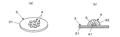
図3(a)に示すように、光源部3は、複数のLED部4が配置される基板31を備える。なお、基板31は、プリント基板やセラミック基板等が使用され、その形状は図示の円形に限らず、多角形などでもよい。また、LED部4はその配置を基板31の中心部などに限定されるものではない。
As shown to Fig.3 (a), the
図3(b)に示すように、LED部4は基板31に装着され可視光領域にピーク波長を有する光を出射するLED素子41と、LED素子41を覆う透明部材からなる封止部42と、封止部42内にLED素子41からの光を波長変換する蛍光体5とを備える。この蛍光体5は波長変換素子であって、かつ、LED素子41からの光の波長を制御する光学部材を成す。LED部4はLED素子41からの光と、このLED素子41からの光が蛍光体5で波長変換された光とにより白色光を発光し、その照射光の分光スペクトルは、その発光波長領域におけるピーク波長の十分の一以下の発光強度となるボトム波長を有する。
As shown in FIG. 3B, the
LED素子41は、青色光を発光するGaN系青色LEDチップ(例えば、豊田合成社製、三菱化学社製のものなど)を用い、目標の青色ピーク波長を示すものであれば、その材料は限定されない。ここでは、LED素子41は400〜450nmの波長帯にピーク波長を有し、蛍光体5を高効率に励起する。なお、LED素子41は基板31上に形成される電源回路(不図示)によりその基板2上の配線パターンを介して給電される。
The
封止部42は、部材に透明樹脂のシリコーン樹脂を用い、キャップ形状を成してLED素子41を覆っている。なお、封止部42はシリコーン樹脂に限らず、アクリル樹脂(PMMA)などを用いてもよく、また、その形状はキャップ型に限らず、砲弾型や半円球状等として集光レンズ機能を持たせてもよい。
The sealing
蛍光体5は、色変換部材の材料のうち、特に発光効率の点で優れているイットリウム・アルミニウム・ガーネット蛍光体(YAG)や、シリケート系蛍光体等を用いることができる。この蛍光体5は封止部42の透明樹脂内に分散保持され、例えばLED素子41からの青色光の一部を吸収し波長変換して黄色光を発光し、この黄色光と、蛍光体5で吸収されなかった残りの青色光とにより白色光が形成される。これらLED素子41と蛍光体5を含む封止部42とは白色光を出射する白色LEDを形成する。
As the
ここでは、蛍光体5はLED素子41と組み合わされ、その出力光の発光スペクトルが目標のピーク波長とボトム波長とを有するように、蛍光材料の選択やシリコン樹脂への配合比の設定、及び複数の蛍光体の混合などを行うことにより形成される。なお、蛍光体5は上記発光波長を制御することが可能であれば何ら限定されるものではない。
Here, the
上記蛍光体5により、LED部4は、LED素子41からの光が波長変換されて発光する際、その発光スペクトルが460〜520nmの波長帯に、そのピーク波長の十分の一以下の発光強度のボトム波長を有するように形成される。
When the light emitted from the
また、LED素子41はピーク波長を400〜450nmの波長帯としているが、その波長帯内でピーク波長の位置を短波長側にすれば、蛍光体5の発光効率がより高まる。このとき、LED素子41は、ピーク波長がその短波長側に寄り過ぎると、LED発光の波長ブロードにより390nm以下の光が出てしまうので、これを避けるため、410〜420nm付近にピーク波長があることが望ましい。
Further, the
図4は、LED部4から照射される光の相対的な分光スペクトルを示す。この分光スペクトルは略440〜450nmの波長帯に最大のピーク波長を有し、このピーク波長の発光強度を相対値1とし正規化表示され、460〜520nmの波長帯に、そのピーク波長に対し相対値0.1以下の発光強度となるボトム波長を有している。
FIG. 4 shows a relative spectral spectrum of light emitted from the
本実施形態によれば、LED部4からの可視光は460〜520nmの波長帯にボトム波長を有し、このボトム波長の発光強度はピーク波長に比べ十分の一以下に大きく低下されている。このとき、ボトム波長は、青色光(400〜450nm付近)と黄色光(例えば、560nm〜600nm付近)の間にあるので、青色光と黄色光の発光強度への影響が少なく、それらの光による白色光の色調は殆ど変化しないようにできる。また、460〜520nmでのボトム波長の発光強度の低減により、昆虫の誘引性のある可視光領域の光の一部を抑制できるので、飛翔昆虫の誘引性を低下することができる。また、LED部4に青色光以外にピーク波長を有するLED素子を追加する必要がないので、簡単な構成で低コストにできる。また、ボトム波長の発光強度の低減に伴う青色光の発光強度の低下は殆どないので、蛍光体5での変換効率が維持され、効率の低下が抑えられる。
According to the present embodiment, the visible light from the
また、LED部4はピーク波長を400〜450nmの波長帯とし、ボトム波長を460〜520nmの波長帯としているので、その発光スペクトルがピーク波長からボトム波長に急峻に低下することにより、白色がきれいに見える。なお、本実施形態はLED光源を使用する全ての照明装置に使用することができる。
In addition, since the
(第2の実施形態)
本発明の第2の実施形態に係る照明装置について、図5乃至図8を参照して説明する。図5に示すように、本実施形態は前記実施形態において、光源部3がLED部4の封止部42の表面側に、所定の波長光の透過を阻止するための波長カットフィルタ6を備えたものである。波長カットフィルタ6は、LEDからの光の波長を制御する光学部材を成す。本実施形態においては、LED部4はLED素子41からの光が波長カットフィルタ6を通過することにより、460〜520nmの波長帯に、発光強度が略ゼロとなるボトム波長を持つ分光スペクトルを有する。この波長カットフィルタ6はLED部4の光出射方向に設けられていればよく、LED部4と共にパッケージングされていなくてもよい。また、波長カットフィルタ6は、複数のLED部を1部材で覆うカバー部材として形成されていてもよい。なお、波長カットフィルタ6の特性を補助するために、蛍光体5によって前記実施形態と同様の光透過特性を持たせるようにしてもよい。
(Second Embodiment)
An illumination device according to a second embodiment of the present invention will be described with reference to FIGS. As shown in FIG. 5, in the present embodiment, the
ここでは、LED部4は、LED素子41を収納する矩形の凹型の枠体43を有し、枠体43はその底面にLED素子41を装着し、その内部は蛍光体5を保持しLED素子41を封止する封止部42の透明樹脂で充満されている。また、枠体43は透明部材から成る平板状の前面フィルタ7でその光出射面側が覆われている。前面フィルタ7は、樹脂やガラスからなる透明部材から成り、ここではガラス部材を用い封止部42から出る光をそのまま透過させる。この前面フィルタ7の上に波長カットフィルタ6が配置される。
Here, the
波長カットフィルタ6は、図6に示すように、前面フィルタ7のガラス基板上に、酸化チタンと酸化ケイ素を順に積層し、8層の膜を成膜して積層された誘電体薄膜から成る光学多層膜を有する。波長カットフィルタ6はこの光学多層膜により所定の波長カット特性を持つ光フィルタとして形成される。この光学多層膜は、具体的には、ガラス上に膜厚400nmの酸化チタンと、膜厚246nmの酸化ケイ素を交互に7層まで積層し、その上に最上層として膜厚100nmの酸化ケイ素を重ねて構成される。
As shown in FIG. 6, the wavelength cut
この波長カットフィルタ6の特性は、光学多層膜において異なる誘電体同士の界面で生じる反射が干渉することにより、光の透過特性が変わることを利用して形成される。なお、光学多層膜における誘電体薄膜の組成、膜厚、及び層構成は、例えば目標のフィルタ特性に基き薄膜設計ソフトウェアを用いたシミュレーション等により設計され、誘電体薄膜は電子ビーム蒸着法等により作成される。また、上記波長を制御することが可能であれば何らフィルタ材料を限定するものではない。
The characteristics of the wavelength cut
この波長カットフィルタ6は、波長カットフィルタ6を透過したLED部4からの光が、460〜520nmの波長帯の少なくとも1箇所の発光強度が略ゼロとなるようにする光透過特性を有するように形成される。なお、この光透過特性は、490nm付近の波長が略ゼロであることが望ましい。また、色調に影響を与えない場合は、460〜520nmの波長帯が全てゼロであってもよい。
The wavelength cut
図7は、波長カットフィルタ6を通る光の概略の透過特性を示す。この光透過特性は、460〜520nmの波長帯で略ゼロのボトム波長を有し、この帯域での透過を阻止する帯域阻止型を成している。図8は、LED部4からの照射光が上記光透過特性を持つ波長カットフィルタ6を透過した光の分光スペクトルを示す。ここでは、略460〜520nmの波長帯内で分光スペクトルが急峻に低下され、これらの波長帯の一部で発光強度がほぼゼロとなっている。
FIG. 7 shows a schematic transmission characteristic of light passing through the wavelength cut
本実施形態によれば、LED部4からの光は460〜520nm波長帯の少なくとも1箇所の発光強度が略ゼロとなるボトム波長を有するので、その波長帯の発光強度がより抑制されるようになり、飛翔昆虫の誘引性をより減少することができる。
According to the present embodiment, the light from the
(第3の実施形態)
本発明の第3の実施形態に係る照明装置について、図9を参照して説明する。図9(a)(b)に示されるように、本実施形態は前記実施形態の光源部3において、LED部4の前面側に帯域阻止型の波長カットフィルタに代えて、390nm以下の短波長帯(高域)側を阻止する高域阻止型の波長カットフィルタ8(光学部材)を備える。本実施形態は、LED部4からの光が波長カットフィルタ8を透過することにより、その放射光の分光スペクトルにおいて390nm以下の波長帯の発光強度が略ゼロとなるものである。
(Third embodiment)
An illumination device according to a third embodiment of the present invention will be described with reference to FIG. As shown in FIGS. 9A and 9B, in the present embodiment, in the
波長カットフィルタ8は、アクリル(PMMA)、ポリカーボネイト樹脂やガラス等の透明部材を用いる。ここでは、波長カットフィルタ8は、LED部4の前面フィルタ7をアクリル樹脂で形成し、そのアクリル樹脂に少なくとも紫外線吸収剤(例えば、チバ社製:チヌビン326他)や染料及び顔料等の添加剤9を添加する。波長カットフィルタ8は、この添加によって390nm以下の短波長帯側をカットするように透過波長を制御する。なお、この添加剤9としては、耐久性及び色調を考えると紫外線吸収剤を使用することが望ましい。
The wavelength cut
また、波長カットフィルタ8は、樹脂やガラスに光学多層膜を積層して、前述と同様に、光フィルタ設計により390nm以下の波長をカットすることによっても形成できる。なお、波長カットフィルタ8は蛍光体5と一体としてもよい。また、波長カットフィルタ8は、その部材にガラス材を用い、ガラス材にハロゲン化物等を添加し、上記波長カットの光透過特性を有する硼珪酸系や、リン酸系等からなる透光性ガラスにより形成してもよい。また、LED素子の組成を制御することによって、LED部4自体において、390nm以下で発光しないようにするようにしてもよい。なお、短波長側に青色の波長ピークがある場合、390nmの光を発するだけでなく、400〜420nm付近の光も多く出すので、波長カットフィルタ8により、405nm以下の発光強度をピーク波長の発光強度に比べ50%以下にすることが望ましい。また、上記波長を制御することが可能であれば何ら材料・方式を限定するものではない。
The wavelength cut
本実施形態によれば、光源部3からの照射光の390nm以下の短波長帯側がカットされることにより、紫外線領域の発光スペクトルが減少し、飛翔昆虫の誘引性がより低下する。また、波長カットフィルタ8を、アクリル樹脂に添加剤9を入れて形成する場合は、光学多層膜を用いないので、低コストで製造することができる。
According to this embodiment, the short wavelength band side of 390 nm or less of the irradiation light from the
次に、上述した実施形態に係る実施例1〜6と、比較例1〜2(実施形態でない)とを対比して説明する。実施例1〜6及び比較例1〜2における照明装置1は、図10(a)、(b)に示すように、水平方向に取り付けられたダウンライト形状とし、光源部3からの光を筐体2の開口21から水平方向に照射するように、部屋の中央部のポール10に取り付けた。光源部3は、筐体2の開口21の光照射面に黒色パネル(木製)を設け、その黒色パネルに穴を開け、その穴の中から照射するように筐体2内に設置した。筐体2の開口21は略500mm角のサイズを成し、その上下端側には、開口21の一部を塞ぐように、幅200×長さ500mmのサイズを成す捕虫用の粘着トラップシート11をそれぞれ取り付けた。光源部3からの光は粘着トラップシート11の間の開口21側からのみが照射されるようにした。ここでは、光源部3は8個のLEDを用いた。照明装置の固定は、パナソニック電工製ダウンライト(NNN21615形状)を用いて実施した。
Next, Examples 1 to 6 according to the above-described embodiment will be described in comparison with Comparative Examples 1 and 2 (not an embodiment). As shown in FIGS. 10A and 10B, the

(測定方法)
照明装置からの分光スペクトルを瞬間マルチ測光システム(MCPD3000:大塚電子社製)を用いて測定し、ピーク波長及びボトム波長における発光強度と共に、ボトム波長のゼロ強度領域を測定した。ボトム波長及びピーク波長における発光強度の比率(B/P比率という)は、ピーク波長の強度を10として計算により算出した。例えば、B/P比率が1.0のときは、ボトム波長の発光強度がピーク波長の十分の1であることを示す。
(Measuring method)
The spectral spectrum from the illumination device was measured using an instantaneous multi-photometry system (MCPD3000: manufactured by Otsuka Electronics Co., Ltd.), and the zero intensity region of the bottom wavelength was measured together with the emission intensity at the peak wavelength and the bottom wavelength. The ratio of emission intensity at the bottom wavelength and the peak wavelength (referred to as B / P ratio) was calculated by calculating the intensity of the peak wavelength as 10. For example, a B / P ratio of 1.0 indicates that the emission intensity at the bottom wavelength is 1 which is a sufficient peak wavelength.
(評価方法)
昆虫を誘引する誘虫性評価は、10m四方の部屋の中に3種類(ハエ、コナガ等)の虫を各400匹離し、1時間後の捕虫数により評価を行った。ここでは、比較例2における虫の総捕虫数を100とし、これを基準値として相対比較を行った。上記条件で測定した評価結果を上記の表1に示す。表1は、縦欄に実施例及び比較例をそれぞれ示し、横欄に順にピーク波長、B/P比率、ボトム波長のゼロ波長領域、短波長以下のカットフィルタの有無、昆虫の誘虫性を示す。また、色調評価は、ダウンライト形状の照明装置からの光を白色板に照射し、その色調を目視評価し、この目視評価で「白」又は「大幅な色調変化なし(黄みが強くない)」場合は、○とし、黄みが強く見える場合は、×とした。
(Evaluation methods)
The insecticidal evaluation for attracting insects was performed by separating 400 insects of 3 types (fly, snapper, etc.) each in a 10 m square room, and evaluating the number of insects captured after 1 hour. Here, the total number of insects captured in Comparative Example 2 was set to 100, and this was used as a reference value for relative comparison. The evaluation results measured under the above conditions are shown in Table 1 above. Table 1 shows the examples and comparative examples in the vertical column, and the peak wavelength, the B / P ratio, the zero wavelength region of the bottom wavelength, the presence or absence of a cut filter of a short wavelength or less, and the insect attractant in order in the horizontal column. . The color tone is evaluated by irradiating a white plate with light from a downlight-shaped lighting device, and visually evaluating the color tone. In this visual evaluation, “white” or “no significant change in color tone (not yellowish). "In the case of"", it was marked as ◯, and in the case where the yellowish color appeared strong, it was marked as" X ".
(実施例1)
実施例1における照明装置は、前記第1の実施形態と同様の構成を成し、青色のピーク波長を発光するLED素子上に、黄色系の蛍光体を配合したシリコン樹脂の封止部を設ける構成とした。それらの発光スペクトルは、ピーク波長を440nmとし、B/P比率は1.0となり、ボトム波長の発光強度がピーク波長の十分の一以下となっている。また、昆虫の誘虫性は85を示し基準値(100)以下となり、飛翔昆虫を誘引し難くできた。また、色調評価は、良好であった。なお、以下の各実施例では、実施例5を除き、ピーク波長を全て440nmとしている。
Example 1
The illuminating device in Example 1 has the same configuration as that of the first embodiment, and a silicon resin sealing portion in which a yellow phosphor is blended is provided on an LED element that emits a blue peak wavelength. The configuration. Their emission spectra have a peak wavelength of 440 nm, a B / P ratio of 1.0, and the bottom wavelength emission intensity is one-tenth or less of the peak wavelength. The insect attractivity was 85, which was below the reference value (100), making it difficult to attract flying insects. Moreover, the color tone evaluation was favorable. In each of the following examples, except for Example 5, the peak wavelength is all 440 nm.
(実施例2)
実施例1における照明装置は、前記第1の実施形態と同様の構成を成し、青色のピーク波長を発光するLED素子上に、2種類の黄色系の蛍光体を配合したシリコン樹脂の封止部を設ける構成とした。この結果、B/P比率は0.5を示し、昆虫の誘虫性は75とより低減された。
(Example 2)
The illumination device in Example 1 has the same configuration as that of the first embodiment, and is sealed with a silicone resin in which two types of yellow phosphors are blended on an LED element that emits a blue peak wavelength. It was set as the structure which provides a part. As a result, the B / P ratio was 0.5, and the insect attractivity was further reduced to 75.
(実施例3)
実施例3における照明装置は、前記第2の実施形態において、波長カットフィルタを図11(a)に示すように、485〜490nmで光透過特性が略ゼロになるものを用いた。この波長カットフィルタは、図11(b)に示すように、耐候性の透明のアクリル樹脂上に8層から成る光学多層膜を形成し、上記の光透過特性を得るように構成した。この結果、B/P比率は0.1以下となり、誘虫性はより低くなった。
(Example 3)
As the illumination device in Example 3, in the second embodiment, a wavelength cut filter having a light transmission characteristic of substantially zero at 485 to 490 nm as shown in FIG. As shown in FIG. 11B, the wavelength cut filter was configured to form an optical multilayer film composed of eight layers on a weather-resistant transparent acrylic resin to obtain the above-described light transmission characteristics. As a result, the B / P ratio was 0.1 or less, and the insect attractivity was further lowered.
(実施例4)
実施例4は、実施例3において、図12(a)に示すように、波長カットフィルタを475〜495nmで光透過特性が略ゼロとなるものとした。この波長カットフィルタは、図12(b)に示すように、耐候性の透明のアクリル樹脂上に20層から成る光学多層膜を形成して、上記の光透過特性を得るように構成した。この結果、B/P比率は0.1以下となり、誘虫性は65を示し、各実施例の中で最も低くなった。
Example 4
In Example 4, as shown in FIG. 12A, the wavelength cut filter is 475 to 495 nm, and the light transmission characteristic becomes substantially zero in Example 3. As shown in FIG. 12B, the wavelength cut filter was configured to form the optical multilayer film consisting of 20 layers on a weather-resistant transparent acrylic resin so as to obtain the above light transmission characteristics. As a result, the B / P ratio was 0.1 or less, the insecticidal property was 65, and was the lowest among the examples.
(実施例5)
実施例5における照明装置は、前記第3の実施形態において、短波長帯を抑制する波長カットフィルタを、アクリル樹脂に紫外線吸収剤、光安定剤等を入れ、405nm以下(300〜405nm)をカットするように構成した。ここでは、ピーク波長を410nmと低くした。この場合も、昆虫の誘虫性は基準値より低くなっている。
(Example 5)
In the illumination device in Example 5, in the third embodiment, the wavelength cut filter for suppressing the short wavelength band is inserted into the acrylic resin with an ultraviolet absorber, a light stabilizer, etc., and cut to 405 nm or less (300 to 405 nm). Configured to do. Here, the peak wavelength was lowered to 410 nm. Also in this case, the insect attractivity is lower than the reference value.
(実施例6)
実施例6における照明装置は、前記第3の実施形態において、図13(a)、(b)に示すように、波長カットフィルタ8として、390nm以下の短波長帯を抑制する高域阻止型の光フィルタを、光学多層膜により構成した。この波長カットフィルタ8は、LED部4上に設けられる透明のアクリル樹脂から成る前面フィルタ7上に積層された14層の光学多層膜により形成される。図13(c)に示すように、この波長カットフィルタ8の光透過特性は、390nm近傍で急峻に低下し、390nm以下の短波長帯側をカットするようになっている。この場合も、昆虫の誘虫性は基準値より低くなる。また、この波長カットフィルタ8は、390nm付近をシャープにカットするので、フィルタの色調(黄み)が特に少なくなる。
(Example 6)
As shown in FIGS. 13A and 13B, the illumination device in Example 6 is a high-frequency blocking type that suppresses a short wavelength band of 390 nm or less as the wavelength cut
(比較例1)
比較例1の照明装置は、前記実施例1において青色光のピーク波長を470nmに変更し、シリコン樹脂へ蛍光体の配合を変更したものである。この結果、B/P比率は1.5を示し、昆虫の誘虫性は120と基準値を越えた。なお、色調評価は良好であった。
(Comparative Example 1)
The illumination device of Comparative Example 1 is obtained by changing the peak wavelength of blue light to 470 nm in Example 1 and changing the blending of the phosphor into the silicon resin. As a result, the B / P ratio was 1.5, and the insect attractivity was 120, exceeding the reference value. The color tone evaluation was good.
(比較例2)
比較例2の照明装置は、前記実施例2において、青色光のピーク波長を455nmに変更し、シリコン樹脂に混合する2種類の黄色系の蛍光体の配合比を変更したものである。この結果、B/P比率は1.2を示した。この場合の昆虫の捕虫数を100と規定し、これを誘虫性の評価基準とした。
(Comparative Example 2)
The illumination device of Comparative Example 2 is obtained by changing the peak wavelength of blue light to 455 nm and changing the blending ratio of two types of yellow phosphors mixed with silicon resin in Example 2. As a result, the B / P ratio was 1.2. In this case, the number of insects caught was defined as 100, and this was used as an evaluation standard for attracting insects.
(比較例3)
比較例3の照明装置は、前記実施例2において、青色光のピーク波長を440nmに変更し、シリコン樹脂に混合する2種類の黄色系の蛍光体の配合比を変更したものである。この結果、B/P比率は2.0を示し、昆虫の誘虫性は110と基準値を越えた。
(Comparative Example 3)
The illumination device of Comparative Example 3 is the same as that of Example 2 except that the peak wavelength of blue light is changed to 440 nm, and the mixing ratio of two types of yellow phosphors mixed with silicon resin is changed. As a result, the B / P ratio was 2.0, and the insect attractivity was 110, exceeding the reference value.
上記評価結果から分かるように、いずれの実施例も、B/P比が1.0以下となり、すなわち、460〜520nmの波長帯に、LED部4の発光波長領域におけるピーク波長の十分の一以下の発光強度のボトム波長を持つ分光スペクトルを有する。これにより、誘虫性が比較例より低減する効果が得られた。特に、実施例3、5は、それぞれ485〜490nm及び475〜495nmでB/P比率0.1以下となり、略ボトムゼロ領域としたことにより、昆虫の誘虫性を比較例2に比べ30%以上低下でき、昆虫に対する忌避効果をより高めることができた。また、390nm及び405nm以下の波長カットフィルタを有した場合にも、誘虫性が基準値より低下した。なお、色調評価は、いずれの場合も良好であった。
As can be seen from the above evaluation results, in all Examples, the B / P ratio is 1.0 or less, that is, in the wavelength band of 460 to 520 nm, one tenth or less of the peak wavelength in the emission wavelength region of the
なお、本発明は、上記の実施形態の構成に限られず、発明の要旨を変更しない範囲で種々の変形が可能である。例えば、上記各実施形態で、波長カットフィルタと蛍光体、及び封士部を一体としてもよい。また、各実施形態の照明装置はダウンライトに限らず、街路灯等のエクステリア照明器具や、ベースライトの照明器具などにも使用でき、LED光源を使用するものであればよい。 In addition, this invention is not restricted to the structure of said embodiment, A various deformation | transformation is possible in the range which does not change the summary of invention. For example, in each of the above embodiments, the wavelength cut filter, the phosphor, and the seal portion may be integrated. Moreover, the illuminating device of each embodiment can be used not only for downlights but also for exterior illuminators such as street lamps, illuminators for base lights, etc., as long as it uses an LED light source.
1 照明装置
4 LED部(LED)
1
Claims (4)
出射光の分光スペクトルが、前記ピーク波長の十分の一以下の発光強度となるボトム波長を460〜520nmの波長帯に有することを特徴とする照明装置。 An LED that emits light having a peak wavelength in the visible light region,
The illuminating device characterized in that the spectral spectrum of the emitted light has a bottom wavelength having a light emission intensity of one-tenth or less of the peak wavelength in a wavelength band of 460 to 520 nm.
Priority Applications (1)
| Application Number | Priority Date | Filing Date | Title |
|---|---|---|---|
| JP2010261803A JP2012113960A (en) | 2010-11-24 | 2010-11-24 | Lighting system |
Applications Claiming Priority (1)
| Application Number | Priority Date | Filing Date | Title |
|---|---|---|---|
| JP2010261803A JP2012113960A (en) | 2010-11-24 | 2010-11-24 | Lighting system |
Publications (1)
| Publication Number | Publication Date |
|---|---|
| JP2012113960A true JP2012113960A (en) | 2012-06-14 |
Family
ID=46497944
Family Applications (1)
| Application Number | Title | Priority Date | Filing Date |
|---|---|---|---|
| JP2010261803A Pending JP2012113960A (en) | 2010-11-24 | 2010-11-24 | Lighting system |
Country Status (1)
| Country | Link |
|---|---|
| JP (1) | JP2012113960A (en) |
Cited By (3)
| Publication number | Priority date | Publication date | Assignee | Title |
|---|---|---|---|---|
| JP2017191692A (en) * | 2016-04-12 | 2017-10-19 | パナソニックIpマネジメント株式会社 | Luminaire |
| KR20190064027A (en) * | 2017-11-30 | 2019-06-10 | 장정걸 | Light module for repelling insects |
| KR20200095216A (en) * | 2019-01-31 | 2020-08-10 | 비에이메테리얼스(주) | White led package for preventing insect |
Citations (4)
| Publication number | Priority date | Publication date | Assignee | Title |
|---|---|---|---|---|
| JP2003133594A (en) * | 2001-10-19 | 2003-05-09 | Seiwa Electric Mfg Co Ltd | Light emitting diode lamp and lighting fixture using the same |
| JP2004261180A (en) * | 2003-02-13 | 2004-09-24 | Matsushita Electric Works Ltd | Insect controlling system |
| JP2007234877A (en) * | 2006-03-01 | 2007-09-13 | Nichia Chem Ind Ltd | Light emitting device |
| WO2010048922A2 (en) * | 2008-10-30 | 2010-05-06 | Osram Opto Semiconductors Gmbh | Lantern, and method for retrofitting a lantern |
-
2010
- 2010-11-24 JP JP2010261803A patent/JP2012113960A/en active Pending
Patent Citations (4)
| Publication number | Priority date | Publication date | Assignee | Title |
|---|---|---|---|---|
| JP2003133594A (en) * | 2001-10-19 | 2003-05-09 | Seiwa Electric Mfg Co Ltd | Light emitting diode lamp and lighting fixture using the same |
| JP2004261180A (en) * | 2003-02-13 | 2004-09-24 | Matsushita Electric Works Ltd | Insect controlling system |
| JP2007234877A (en) * | 2006-03-01 | 2007-09-13 | Nichia Chem Ind Ltd | Light emitting device |
| WO2010048922A2 (en) * | 2008-10-30 | 2010-05-06 | Osram Opto Semiconductors Gmbh | Lantern, and method for retrofitting a lantern |
Cited By (5)
| Publication number | Priority date | Publication date | Assignee | Title |
|---|---|---|---|---|
| JP2017191692A (en) * | 2016-04-12 | 2017-10-19 | パナソニックIpマネジメント株式会社 | Luminaire |
| KR20190064027A (en) * | 2017-11-30 | 2019-06-10 | 장정걸 | Light module for repelling insects |
| KR102072392B1 (en) | 2017-11-30 | 2020-02-03 | 장정걸 | Light module for repelling insects |
| KR20200095216A (en) * | 2019-01-31 | 2020-08-10 | 비에이메테리얼스(주) | White led package for preventing insect |
| KR102263850B1 (en) * | 2019-01-31 | 2021-06-11 | 비에이메테리얼스(주) | White led package for preventing insect |
Similar Documents
| Publication | Publication Date | Title |
|---|---|---|
| JP5906433B2 (en) | Lighting device | |
| EP3323146B1 (en) | Use of a light emitting diode based lighting device for disinfection | |
| JP5796211B2 (en) | Lighting device and lighting system using the same | |
| JP4023329B2 (en) | Optical filter and lighting apparatus using the same | |
| US9041277B2 (en) | Lighting device | |
| CN103363345B (en) | Light-emitting device, lighting apparatus and use its light fixture | |
| JP2006059625A (en) | Led illumination device, pendant illumination fixture, and street lgt | |
| JP2009117825A (en) | White light emitting device | |
| JP2009524247A5 (en) | ||
| JP2013515366A5 (en) | ||
| JP6726857B2 (en) | Street light | |
| JP5974394B2 (en) | White light emitting device and lighting apparatus using the same | |
| JP2012113960A (en) | Lighting system | |
| JP2012174538A (en) | Lighting system with low insect-inducing property | |
| JP2013026046A (en) | Lighting device | |
| CN105552066B (en) | The white light source of improvement and its application | |
| JP3202377U (en) | Light source device | |
| KR100855732B1 (en) | Flat panel lighting equipment | |
| RU2693632C1 (en) | Light-emitting diode light source with biologically adequate radiation spectrum | |
| KR101819912B1 (en) | Illumination system with light source, radiation converting element and filter | |
| JP6562343B2 (en) | Wavelength control filter, light emitting device and lighting device using the same | |
| JP4023519B2 (en) | Optical filter and lighting apparatus using the same | |
| CN220623728U (en) | Lighting device and lighting equipment | |
| JP7464861B2 (en) | Light-emitting devices, lighting fixtures and street lights | |
| JP7599111B2 (en) | Light-emitting devices for mesopic environments, outdoor lighting devices, and emergency lighting devices |
Legal Events
| Date | Code | Title | Description |
|---|---|---|---|
| A621 | Written request for application examination |
Free format text: JAPANESE INTERMEDIATE CODE: A621 Effective date: 20131021 |
|
| A977 | Report on retrieval |
Free format text: JAPANESE INTERMEDIATE CODE: A971007 Effective date: 20140624 |
|
| A131 | Notification of reasons for refusal |
Free format text: JAPANESE INTERMEDIATE CODE: A131 Effective date: 20140701 |
|
| A521 | Written amendment |
Free format text: JAPANESE INTERMEDIATE CODE: A523 Effective date: 20140822 |
|
| A02 | Decision of refusal |
Free format text: JAPANESE INTERMEDIATE CODE: A02 Effective date: 20141007 |
|
| A711 | Notification of change in applicant |
Free format text: JAPANESE INTERMEDIATE CODE: A711 Effective date: 20141007 |
|
| RD03 | Notification of appointment of power of attorney |
Free format text: JAPANESE INTERMEDIATE CODE: A7423 Effective date: 20141023 |
|
| A521 | Written amendment |
Free format text: JAPANESE INTERMEDIATE CODE: A523 Effective date: 20141201 |
|
| A911 | Transfer to examiner for re-examination before appeal (zenchi) |
Free format text: JAPANESE INTERMEDIATE CODE: A911 Effective date: 20141209 |
|
| A912 | Re-examination (zenchi) completed and case transferred to appeal board |
Free format text: JAPANESE INTERMEDIATE CODE: A912 Effective date: 20150123 |