JP2012110080A - Non-contact type power transmission device, and, power supply device, power reception device, and electromagnetic induction coil used therefor - Google Patents
Non-contact type power transmission device, and, power supply device, power reception device, and electromagnetic induction coil used therefor Download PDFInfo
- Publication number
- JP2012110080A JP2012110080A JP2010255216A JP2010255216A JP2012110080A JP 2012110080 A JP2012110080 A JP 2012110080A JP 2010255216 A JP2010255216 A JP 2010255216A JP 2010255216 A JP2010255216 A JP 2010255216A JP 2012110080 A JP2012110080 A JP 2012110080A
- Authority
- JP
- Japan
- Prior art keywords
- coil
- planar
- coils
- power
- feeding
- Prior art date
- Legal status (The legal status is an assumption and is not a legal conclusion. Google has not performed a legal analysis and makes no representation as to the accuracy of the status listed.)
- Granted
Links
Images


Classifications
-
- H—ELECTRICITY
- H01—ELECTRIC ELEMENTS
- H01F—MAGNETS; INDUCTANCES; TRANSFORMERS; SELECTION OF MATERIALS FOR THEIR MAGNETIC PROPERTIES
- H01F27/00—Details of transformers or inductances, in general
- H01F27/28—Coils; Windings; Conductive connections
- H01F27/2871—Pancake coils
-
- H—ELECTRICITY
- H01—ELECTRIC ELEMENTS
- H01F—MAGNETS; INDUCTANCES; TRANSFORMERS; SELECTION OF MATERIALS FOR THEIR MAGNETIC PROPERTIES
- H01F38/00—Adaptations of transformers or inductances for specific applications or functions
- H01F38/14—Inductive couplings
Abstract
Description
本発明は、電磁誘導を利用して給電コイルと受電コイルとの間で電力を伝送する非接触式電力伝送装置、並びにこれに用いられる給電装置、受電装置及び電磁誘導用コイルに関する。 The present invention relates to a non-contact power transmission device that transmits electric power between a power feeding coil and a power receiving coil using electromagnetic induction, and a power feeding device, a power receiving device, and an electromagnetic induction coil used therefor.
従来から電磁誘導を利用して給電装置から受電装置に電力を伝送する非接触式電力伝送装置が知られている。 図30は、非接触式電力電送装置300の回路の等価回路図である。この図30に示すように給電装置301は、コンデンサ302及びコイルを直列に接続してなる共振回路を具備し、交流電源304から交流電圧を印加するように構成されている。共振回路を構成しているコイルが給電コイル303である。なお、図に示した抵抗305はキャパシタを駆動する回路の内部抵抗Rpを表している。一方、受電装置310は受電コイル311を具備しており、電力伝送の際には、受電コイル311が給電コイル303と対向されるように配される。なお、受電装置310側に示した抵抗312は負荷抵抗RLを表している。
2. Description of the Related Art Conventionally, a non-contact power transmission device that transmits power from a power feeding device to a power receiving device using electromagnetic induction is known. FIG. 30 is an equivalent circuit diagram of a circuit of the non-contact
非接触式電力伝送装置300は、給電コイル303と受電コイル311とが対向されて配された状態で、給電コイル303が形成する磁束の影響を受電コイル311に与える電磁誘導を利用するものである。
The non-contact
近年、携帯端末等の分野では、その充電手法として、電磁誘導を利用する試みがなされ始めている(例えば、特許文献1参照)。 In recent years, in the field of mobile terminals and the like, attempts have been made to use electromagnetic induction as a charging method (see, for example, Patent Document 1).
もっとも、非接触式電力電送装置は、一つの磁性体に一次コイルと二次コイルの双方向巻き付けて構成した通常のトランスと比較して伝送効率が低いという難点がある。このため、非接触式電力伝送装置において、伝送効率を向上するための試みも従来からなされている(例えば、特許文献2参照)。 However, the non-contact power transmission device has a drawback in that the transmission efficiency is low as compared with a normal transformer configured by winding a primary coil and a secondary coil around one magnetic body. For this reason, attempts have been made in the past to improve transmission efficiency in contactless power transmission devices (see, for example, Patent Document 2).
この特許文献2に開示の発明では、消費電力の低減を図るべく、給電装置側の1次側誘導コイルと受電装置側の2次側誘導コイルにコンデンサをそれぞれ並列接続し、この並列接続によって給電装置である充電器及び受電装置であるコードレス機器とLC並列共振回路を構成している。また、1次側誘導コイルと2次側誘導コイルをシートコイルにより構成し、これらを、充電状態時において所定のギャップをおいて相対向させるようにしている。特許文献2の発明は、このような構成を採用することで、相互誘導を適正なギャップで行えるようにしたものである。 In the invention disclosed in Patent Document 2, capacitors are connected in parallel to the primary side induction coil on the power feeding device side and the secondary side induction coil on the power reception device side in order to reduce power consumption, and power is fed by this parallel connection. An LC parallel resonance circuit is configured with a charger as a device and a cordless device as a power receiving device. In addition, the primary induction coil and the secondary induction coil are constituted by sheet coils, and they are opposed to each other with a predetermined gap in the charged state. The invention of Patent Document 2 adopts such a configuration so that mutual induction can be performed with an appropriate gap.
しかしながら、電力伝送の効率を向上させるためには、給電コイルと受電コイルの間におけるギャップを適正化するだけでは自ずと限界がある。電力電送の効率を向上させるためには、電磁誘導の能力それ自体を向上させることがどうしても必要となる。しかも、携帯端末などの小型機器をも対象とするには、電力電送装置を小型にしつつ電磁誘導の能力を向上させることが必須となる。 However, in order to improve the efficiency of electric power transmission, there is a limit naturally only by optimizing the gap between the feeding coil and the receiving coil. In order to improve the efficiency of electric power transmission, it is necessary to improve the electromagnetic induction capability itself. Moreover, in order to target small devices such as portable terminals, it is essential to improve the electromagnetic induction capability while reducing the size of the power transmission device.
本発明では、かかる問題点に鑑みてなされたものであり、電力電送装置を小型に維持しつつ、高い効率で伝よく伝送することができる非接触式電力伝送装置、並びにこれに用いられる給電装置及び電磁誘導用コイルを提供することを目的とする。 The present invention has been made in view of such a problem, and a non-contact power transmission device that can transmit power efficiently and efficiently while maintaining a small size of the power transmission device, and a power supply device used therefor And it aims at providing the coil for electromagnetic induction.
(1)本発明では上記課題を解決するために、素線を渦巻状に巻いて形成した平面コイルからなる給電コイルを備えた給電装置と、素線を渦巻状に巻いて形成した平面コイルからなる受電コイルを備えた受電装置とを備え、前記給電コイルと前記受電コイルとの間で電磁誘導を利用して前記給電装置から前記受電装置に電力を伝送する非接触式電力伝送装置であって、前記給電装置は、前記給電コイルを含めて構成される共振回路を有し、前記給電コイルは、複数の平面コイルで構成され、これら複数の平面コイルは、その素線が同一軸を中心として巻かれて形成され、かつ互いの自己インダクタンスの値が略同値とされたことを特徴とする非接触式電力伝送装置を採用した。 (1) In the present invention, in order to solve the above-described problem, a power supply device including a power supply coil including a planar coil formed by winding a wire in a spiral shape, and a planar coil formed by winding the wire in a spiral shape A non-contact power transmission device that transmits power from the power feeding device to the power receiving device using electromagnetic induction between the power feeding coil and the power receiving coil. The power feeding device has a resonance circuit including the power feeding coil, and the power feeding coil is composed of a plurality of planar coils, and the plurality of planar coils have their strands centered on the same axis. A non-contact power transmission device characterized by being wound and having a self-inductance value of approximately the same value was employed.
(2)この非接触式電力伝送装置において、前記給電コイルは、前記複数の平面コイルが一平面をなして構成されたことを特徴とする。 (2) In this non-contact power transmission device, the power supply coil is configured such that the plurality of planar coils form one plane.
(3)また、前記給電コイルを構成する複数の平面コイルは、中央に空間部がそれぞれ形成され、かつ、相互の内縁寸法及び外縁寸法が順次小さくなるように形成され、前記複数の平面コイルは、それぞれの前記空間部に外縁寸法の小さな平面コイルが順次配置され、前記複数の平面コイルは並列接続されていることを特徴とする。 (3) Further, the plurality of planar coils constituting the feeding coil are formed such that a space portion is formed at the center and the inner edge dimension and the outer edge dimension are sequentially reduced, and the plurality of planar coils are The planar coils having small outer edge dimensions are sequentially arranged in the space portions, and the plurality of planar coils are connected in parallel.
(4)この場合において、前記給電コイルを構成する平面コイルのうち最内部に配置された平面コイルの外縁寸法は、前記受電コイルの外縁寸法と略同寸に形成されていることを特徴とする。 (4) In this case, the outer edge dimension of the planar coil arranged at the innermost of the planar coils constituting the power supply coil is formed to be substantially the same as the outer edge dimension of the power receiving coil. .
(5)また、前記給電コイルを構成する平面コイルは、少なくとも最内部に配された平面コイルが、並列に並べられた2本の素線が同一軸を中心に巻かれて形成された2つの平面コイルにより構成され、かつ、前記2つの平面コイルは並列接続され、前記2つの平面コイルのそれぞれの巻数が前記受電コイルの巻数よりも少なくなるよう構成されている。 (5) Further, the planar coil constituting the feeding coil is formed by two planar coils arranged at least on the innermost side, in which two strands arranged in parallel are wound around the same axis. The two planar coils are configured in parallel, and are connected in parallel so that the number of turns of each of the two planar coils is smaller than the number of turns of the power receiving coil.
(6)あるいは、前記給電コイルを構成する平面コイルのうち少なくとも最内部に配された平面コイルは、並列に並べられた複数の素線が同一軸を中心に巻かれて形成された平面コイル群により構成され、前記平面コイル群を構成する各平面コイルは、前記受電コイルの巻数よりも少なく巻かれ、前記平面コイル群の中から選択された平面コイルに電流が流されるように構成する。 (6) Alternatively, the planar coil arranged at least in the innermost of the planar coils constituting the feeding coil is a planar coil group formed by winding a plurality of strands arranged in parallel around the same axis. Each planar coil constituting the planar coil group is wound less than the number of turns of the power receiving coil, and a current is passed through the planar coil selected from the planar coil group.
(7)あるいは、前記給電コイルを構成する平面コイルのうち少なくとも最内部に配された平面コイルは、並列に並べられた少なくとも4本の素線が同一軸を中心に巻かれて形成された平面コイル群により構成され、前記平面コイル群を構成する各平面コイルは、前記受電コイルの巻数よりも少なく巻かれ、前記平面コイル群の中から、それぞれの間に少なくとも1本の素線を挟んで選択された複数の素線により構成される平面コイルを並列に接続して電流が流されるように構成することもできる。 (7) Alternatively, among the planar coils constituting the feeding coil, the planar coil arranged at least in the innermost part is a plane formed by winding at least four strands arranged in parallel around the same axis. Each planar coil that is configured of a coil group and that constitutes the planar coil group is wound less than the number of turns of the power receiving coil, and at least one strand is sandwiched between each of the planar coil groups. A planar coil constituted by a plurality of selected strands may be connected in parallel so that a current flows.
(8)このような場合に、前記受電コイルは、並列に並べられた複数の素線が同一軸を中心に巻かれて形成された平面コイル群により構成され、受電側の前記平面コイル群の中から選択された平面コイルが電磁誘導に利用されるように構成すると更によい。 (8) In such a case, the power receiving coil is constituted by a planar coil group formed by winding a plurality of strands arranged in parallel around the same axis, and the power receiving coil of the planar coil group on the power receiving side It is further preferable that a planar coil selected from among them is used for electromagnetic induction.
(9)また、本発明における非接触式電力伝送装置では、前記給電コイルは、並列に並べられた2本の素線が同一軸を中心に巻かれて形成された2つの平面コイルから構成され、前記2つの平面コイルは並列接続されたことを特徴とする。 (9) Moreover, in the non-contact power transmission device according to the present invention, the feeding coil is configured by two planar coils formed by winding two strands arranged in parallel around the same axis. The two planar coils are connected in parallel.
(10)あるいは、前記給電コイルは、並列に並べられた複数の素線が同一軸を中心に巻かれて形成された平面コイル群により構成され、前記平面コイル群を構成する各平面コイルは、前記受電コイルの巻数よりも少なく巻かれて形成され、前記平面コイル群の中から選択された平面コイルに電流が流されるように構成してもよい。 (10) Alternatively, the power supply coil is configured by a planar coil group formed by winding a plurality of strands arranged in parallel around the same axis, and each planar coil constituting the planar coil group includes: The coil may be formed by winding less than the number of turns of the power receiving coil, and a current may be passed through a planar coil selected from the planar coil group.
(11)あるいは、前記給電コイルは、並列に並べられた少なくとも4本の素線が同一軸を中心に巻かれて形成された平面コイル群により構成され、前記平面コイル群を構成する各平面コイルは、前記受電コイルの巻数よりも少なく巻かれ、前記平面コイル群の中から、それぞれの間に少なくとも1本の素線を挟んで選択された複数の素線により構成される平面コイルを並列に接続して電流が流されるように構成することもできる。 (11) Alternatively, the power supply coil is configured by a planar coil group formed by winding at least four strands arranged in parallel around the same axis, and each planar coil constituting the planar coil group Is arranged in parallel with a plurality of strands selected from the group of planar coils, with at least one strand sandwiched between them. It can also be configured to be connected to allow current to flow.
(12)なお、このような場合において、前記受電コイルは、並列に並べられた複数の素線が同一軸を中心に巻かれて形成された平面コイル群により構成され、受電側の前記平面コイル群の中から選択された平面コイルが電磁誘導に利用されるようにするとよい。 (12) In such a case, the power receiving coil is constituted by a planar coil group formed by winding a plurality of strands arranged in parallel around the same axis, and the power receiving side planar coil. A planar coil selected from the group may be used for electromagnetic induction.
(13)また、本発明おける非接触式電力伝送装置では、前記給電コイルは、2つの平面コイルから構成され、前記2つの平面コイルが直列接続されていることを特徴とする。 (13) Moreover, in the non-contact power transmission device according to the present invention, the feeding coil is configured by two planar coils, and the two planar coils are connected in series.
(14)この場合に、前記2つの平面コイルは、並列に並べられた2本の素線が同一軸を中心に巻かれて形成され、各平面コイルの最内周の素線同士が接続されるように構成するとよい。 (14) In this case, the two planar coils are formed by winding two strands arranged in parallel around the same axis, and the innermost strands of each planar coil are connected to each other. It is good to comprise so that.
(15)また、本発明では上記課題を解決するために、素線を渦巻状に巻いて形成した平面コイルからなる給電コイルから、素線を渦巻状に巻いて形成した平面コイルからなる受電コイルに対し電磁誘導を利用して電力を伝送するために使用される給電装置であって、前記給電装置は、前記給電コイルを含めて構成される共振回路を有し、前記給電コイルは、複数の平面コイルで構成され、これら複数の平面コイルは、その素線が同一軸を中心として巻かれて形成され、かつ互いの自己インダクタンスの値が略同値とされた給電装置を採用した。 (15) Further, in order to solve the above-described problems, the present invention provides a power receiving coil comprising a planar coil formed by winding a wire in a spiral shape from a feeding coil comprising a planar coil formed by winding the wire in a spiral shape. The power supply device is used to transmit power using electromagnetic induction. The power supply device includes a resonance circuit including the power supply coil, and the power supply coil includes a plurality of power supply coils. Each of the plurality of planar coils is formed of a planar coil, and the feeder is formed by winding the strands around the same axis, and the self-inductance value of each other is substantially the same.
(16)前記給電コイルは、前記複数の平面コイルが一平面をなして構成されたことを特徴とする。 (16) The power supply coil is characterized in that the plurality of planar coils are configured as one plane.
(17)そして、上記給電装置において、前記給電コイルを構成する複数の平面コイルは、中央に空間部がそれぞれ形成され、かつ、相互の内縁寸法及び外縁寸法が順次小さくなるように形成され、前記複数の平面コイルは、それぞれの前記空間部に外縁寸法の小さな平面コイルが順次配置され、前記複数の平面コイルは並列接続されていることを特徴とする。 (17) In the power feeding device, the plurality of planar coils constituting the power feeding coil are formed such that a space portion is formed at the center, and the inner edge dimension and the outer edge dimension are sequentially reduced, A plurality of planar coils are characterized in that planar coils having small outer edge dimensions are sequentially arranged in the space portions, and the plurality of planar coils are connected in parallel.
(18)この場合において、前記給電コイルを構成する平面コイルのうち少なくとも最内部に配された平面コイルは、並列に並べられた2本の素線が同一軸を中心に巻かれて形成された2つの平面コイルにより構成され、前記2つの平面コイルが並列接続されるように構成するとよい。 (18) In this case, at least the planar coil arranged in the innermost of the planar coils constituting the feeding coil is formed by winding two strands arranged in parallel around the same axis. It is good to comprise so that it may be comprised by two planar coils and the said two planar coils may be connected in parallel.
(19)あるいは、前記給電コイルを構成する平面コイルのうち少なくとも最内部に配された平面コイルは、並列に並べられた複数の素線が同一軸を中心に巻かれて形成された平面コイル群により構成され、前記平面コイル群の中から選択された平面コイルに電流が流されるように構成することもできる。 (19) Alternatively, among the planar coils constituting the power supply coil, the planar coil arranged at least in the innermost part is a planar coil group formed by winding a plurality of strands arranged in parallel around the same axis. It can also be configured such that a current flows through a planar coil selected from the planar coil group.
(20)あるいは、前記給電コイルを構成する平面コイルのうち少なくとも最内部に配された平面コイルは、並列に並べられた少なくとも4本の素線が同一軸を中心に巻かれて形成された平面コイル群により構成され、前記平面コイル群の中から、それぞれの間に少なくとも1本の素線を挟んで選択された複数の素線により構成される平面コイルを並列に接続して電流が流されるように構成してもよい。 (20) Alternatively, at least the planar coil arranged in the innermost of the planar coils constituting the feeding coil is a plane formed by winding at least four strands arranged in parallel around the same axis. A current is flowed by connecting in parallel a plurality of strands composed of a plurality of strands selected from among the planar coils and sandwiching at least one strand therebetween. You may comprise as follows.
(21)また、本発明では上記給電装置において、前記給電コイルは、並列に並べられた2本の素線が同一軸を中心に巻かれて形成された2つの平面コイルから構成され、前記2つの平面コイルは並列接続されたことを特徴とする。 (21) In the present invention, in the above-described power supply device, the power supply coil includes two planar coils formed by winding two strands arranged in parallel around the same axis, and the 2 Two planar coils are connected in parallel.
(22)あるいは、前記給電コイルは、並列に並べられた複数の素線が同一軸を中心に巻かれて形成された平面コイル群により構成され、前記平面コイル群の中から択一的に選択された平面コイルに電流が流されるようにしてもよい。 (22) Alternatively, the feeding coil is constituted by a planar coil group formed by winding a plurality of strands arranged in parallel around the same axis, and is alternatively selected from the planar coil group A current may be passed through the planar coil formed.
(23)あるいは、前記給電コイルは、並列に並べられた少なくとも4本の素線が同一軸を中心に巻かれて形成された平面コイル群により構成され、前記平面コイル群の中から、それぞれの間に少なくとも1本の素線を挟んで選択された複数の素線により構成される平面コイルを並列に接続して電流が流されるようにしてもよい。 (23) Alternatively, the power supply coil is configured by a planar coil group formed by winding at least four strands arranged in parallel around the same axis, and each of the planar coil groups includes: A planar coil composed of a plurality of strands selected with at least one strand interposed therebetween may be connected in parallel so that current flows.
(24)また、上記給電装置において本発明では、前記給電コイルは、2つの平面コイルから構成され、前記2つの平面コイルが直列接続されていることを特徴とする。 (24) Further, in the above-described power supply apparatus, the power supply coil includes two planar coils, and the two planar coils are connected in series.
(25)この場合に、前記2つの平面コイルは、並列に並べられた2本の素線が同一軸を中心に巻かれて形成され、各平面コイルの最内周の素線同士が接続されるように構成するとよい。 (25) In this case, the two planar coils are formed by winding two strands arranged in parallel around the same axis, and the innermost strands of each planar coil are connected to each other. It is good to comprise so that.
(26)また、本発明では上記課題を解決するために、素線を渦巻状に巻いて形成した平面コイルからなる給電コイルから、素線を渦巻状に巻いて形成した平面コイルからなる受電コイルに対し電磁誘導を利用して電力を伝送するために使用される受電装置であって、前記受電コイルは、並列に並べられた複数の素線が同一軸を中心に巻かれて形成された平面コイル群により構成され、受電側の前記平面コイル群の中から選択された平面コイルが電磁誘導に利用される受電装置を採用した。 (26) Further, in the present invention, in order to solve the above-described problem, a power receiving coil including a planar coil formed by winding a wire in a spiral shape from a power feeding coil including a planar coil formed by winding the wire in a spiral shape. A power receiving device used for transmitting electric power using electromagnetic induction, wherein the power receiving coil is a plane formed by winding a plurality of parallel wires arranged around the same axis. A power receiving device that is configured by a coil group and that uses a planar coil selected from the planar coil group on the power receiving side for electromagnetic induction is employed.
(27)また、本発明では上記課題を解決するために、素線を渦巻状に巻いて形成した平面コイルからなる給電コイルと、素線を渦巻状に巻いて形成した平面コイルからなる受電コイルとの間で電磁誘導を利用して電力を伝送する非接触式電力伝送装置に使用される電磁誘導用コイルであって、前記給電コイルは、複数の平面コイルで構成され、これら複数の平面コイルは、その素線が同一軸を中心として巻かれて形成され、かつ互いの自己インダクタンスの値が略同値とされた電磁誘導用コイルを採用することとした。 (27) Further, in the present invention, in order to solve the above-described problem, a power feeding coil including a planar coil formed by winding a wire in a spiral shape, and a power receiving coil including a planar coil formed by winding the wire in a spiral shape An electromagnetic induction coil used in a non-contact power transmission device that transmits electric power using electromagnetic induction between the power supply coil and the plurality of planar coils. Has adopted a coil for electromagnetic induction in which the element wires are wound around the same axis and the self-inductance values of the elements are substantially the same.
(28)この電磁誘導用コイルに関し、前記給電コイルは、前記複数の平面コイルが一平面をなして構成されたことを特徴とする。 (28) With respect to this electromagnetic induction coil, the power supply coil is characterized in that the plurality of planar coils are formed in one plane.
(29)また、上記電磁誘導用コイルに関し、前記給電コイルを構成する複数の平面コイルは、中央に空間部がそれぞれ形成され、かつ、相互の内縁寸法及び外縁寸法が順次小さくなるように形成され、前記複数の平面コイルは、それぞれの前記空間部に外縁寸法の小さな平面コイルが順次配置され、前記複数の平面コイルは並列接続されていることを特徴とする。 (29) In addition, regarding the electromagnetic induction coil, the plurality of planar coils constituting the power supply coil are formed such that a space portion is formed at the center and the inner edge dimension and the outer edge dimension are sequentially reduced. The plurality of planar coils are characterized in that planar coils having small outer edge dimensions are sequentially arranged in the space portions, and the plurality of planar coils are connected in parallel.
(30)この場合において、前記給電コイルを構成する平面コイルのうち最内部に配された平面コイルの外縁寸法は、前記受電コイルの外縁寸法と略同寸に形成されるように構成するとよい。 (30) In this case, it is preferable that the outer edge dimension of the planar coil arranged at the innermost of the planar coils constituting the power feeding coil is formed to be substantially the same as the outer edge dimension of the power receiving coil.
(31)また、上記電磁誘導用コイルにおいて、前記給電コイルを構成する平面コイルのうち少なくとも最内部に配された平面コイルが、並列に並べられた2本の素線が同一軸を中心に巻かれて形成された2つの平面コイルにより構成され、かつ前記2つの平面コイルは並列接続され、前記2つの平面コイルのそれぞれの巻数が前記受電コイルの巻数よりも少なくなるように構成する。 (31) Further, in the electromagnetic induction coil, at least two of the planar coils arranged in the innermost of the planar coils constituting the feeding coil are wound around the same axis. The two planar coils are connected in parallel so that the number of turns of each of the two planar coils is smaller than the number of turns of the power receiving coil.
(32)あるいは、前記給電コイルを構成する平面コイルのうち少なくとも最内部に配された平面コイルは、並列に並べられた複数の素線が同一軸を中心に巻かれて形成された平面コイル群により構成され、前記平面コイル群を構成する各平面コイルは、前記受電コイルの巻数よりも少なく巻かれて形成され、前記平面コイル群には、この平面コイル群を構成する各平面コイルの中から電流を流す平面コイルを選択可能とする接続端子が設けられるようにしてもよい。 (32) Alternatively, among the planar coils constituting the power supply coil, the planar coil arranged at least in the innermost part is a planar coil group formed by winding a plurality of strands arranged in parallel around the same axis. Each planar coil that constitutes the planar coil group is formed by winding less than the number of turns of the power receiving coil, and the planar coil group includes the planar coils that constitute the planar coil group. You may make it provide the connection terminal which enables selection of the planar coil which sends an electric current.
(33)あるいは、前記給電コイルを構成する平面コイルのうち少なくとも最内部に配された平面コイルは、並列に並べられた少なくとも4本の素線が同一軸を中心に巻かれて形成された平面コイル群により構成され、前記平面コイル群を構成する各平面コイルは、前記受電コイルの巻数よりも少なく巻かれて形成され、前記平面コイル群には、この平面コイル群を構成する各平面コイルの中から電流を流す複数の平面コイルを、選択されない他の平面コイルの素線をそれぞれの間に挟んで選択可能な接続端子が設けられ、選択された前記複数の平面コイルが並列に接続されるようにしてもよい。 (33) Alternatively, at least the planar coil arranged at the innermost of the planar coils constituting the feeding coil is a plane formed by winding at least four strands arranged in parallel around the same axis. Each planar coil that is constituted by a coil group and that constitutes the planar coil group is formed by winding less than the number of turns of the power receiving coil, and the planar coil group includes each planar coil that constitutes the planar coil group. A plurality of planar coils through which a current flows can be selected, and a selection terminal is provided by sandwiching a wire of another non-selected planar coil between them, and the selected planar coils are connected in parallel. You may do it.
(34)このような場合に、選択すべき前記平面コイルを構成する素線には、他の平面コイルと区別する識別手段を設けるとよい。 (34) In such a case, an identification means for distinguishing from other planar coils may be provided on the wire constituting the planar coil to be selected.
(35)また、上記の電磁誘導用コイルのように給電コイルを構成した場合において、前記受電コイルは、並列に並べられた複数の素線が同一軸を中心に巻かれて形成された平面コイル群により構成され、受電側の前記平面コイル群には、この平面コイル群の中から電磁誘導に利用される平面コイルを選択可能な接続端子が設けられたことを特徴とする。 (35) Further, in the case where a power feeding coil is configured like the above-described electromagnetic induction coil, the power receiving coil is a planar coil formed by winding a plurality of strands arranged in parallel around the same axis. The planar coil group on the power receiving side is provided with a connection terminal capable of selecting a planar coil used for electromagnetic induction from the planar coil group.
(36)この場合においても、選択すべき平面コイルを構成する素線には、他の平面コイルと区別する識別手段を設けるとよい。 (36) Even in this case, it is preferable to provide identification means for distinguishing the other planar coils from the strands constituting the planar coil to be selected.
(37)また、本発明では上記電磁誘導用コイルにおいて、前記給電コイルを構成する平面コイルは、並列に並べられた2本の素線が同一軸を中心に巻かれて形成された2つの平面コイルにより構成され、かつ前記2つの平面コイルは並列接続され、前記2つの平面コイルのそれぞれの巻数が前記受電コイルの巻数よりも少ないことを特徴とする。 (37) In the present invention, in the above-described electromagnetic induction coil, the planar coil constituting the feeding coil is formed by two planes formed by winding two parallel wires arranged around the same axis. The two planar coils are configured in parallel, and the number of turns of each of the two planar coils is smaller than the number of turns of the power receiving coil.
(38)あるいは、前記給電コイルは、並列に並べられた複数の素線が同一軸を中心に巻かれて形成された平面コイル群により構成され、前記平面コイル群を構成する各平面コイルは、前記受電コイルの巻数よりも少なく巻かれ、前記平面コイル群には、この平面コイル群を構成する各平面コイルの中から電流を流す平面コイルを選択可能とする接続端子が設けられている。 (38) Alternatively, the power supply coil is configured by a planar coil group formed by winding a plurality of strands arranged in parallel around the same axis, and each planar coil constituting the planar coil group includes: The number of turns of the power receiving coil is less than the number of turns of the power receiving coil, and the planar coil group is provided with a connection terminal that allows selection of a planar coil through which a current flows from each planar coil constituting the planar coil group.
(39)あるいは、前記給電コイルは、並列に並べられた少なくとも4本の素線が同一軸を中心に巻かれて形成された平面コイル群により構成され、前記平面コイル群を構成する各平面コイルは、前記受電コイルの巻数よりも少なく巻かれ、前記平面コイル群には、この平面コイル群を構成する各平面コイルの中から電流を流す複数の平面コイルを、選択されない他の平面コイルの素線をそれぞれの間に挟んで選択可能な接続端子が設けられ、選択された前記複数の平面コイルが並列に接続されている。 (39) Alternatively, the feeding coil is configured by a planar coil group formed by winding at least four strands arranged in parallel around the same axis, and each planar coil constituting the planar coil group Is wound less than the number of turns of the power receiving coil, and the planar coil group includes a plurality of planar coils that conduct current from among the planar coils that constitute the planar coil group, and other planar coil elements that are not selected. A selectable connection terminal is provided with a wire sandwiched between them, and the selected planar coils are connected in parallel.
(40)このような場合において、選択すべき平面コイルを構成する素線には、他の平面コイルと区別する識別手段を設けるとよい。 (40) In such a case, an identification means for distinguishing from other planar coils may be provided on the wire constituting the planar coil to be selected.
(41)また、上記電磁誘導用コイルにおいて、給電コイルを上記のように構成した場合、前記受電コイルは、並列に並べられた複数の素線が同一軸を中心に巻かれて形成された平面コイル群により構成され、前記平面コイル群には、この平面コイル群を構成する各平面コイルの中から電磁誘導に利用する平面コイルを選択可能とする接続端子が設けられるように構成するとよい。 (41) Further, in the electromagnetic induction coil, when the feeding coil is configured as described above, the power receiving coil is a plane formed by winding a plurality of strands arranged in parallel around the same axis. It is good to comprise so that it may be comprised by a coil group and the said flat coil group may be provided with the connecting terminal which can select the planar coil utilized for electromagnetic induction from each planar coil which comprises this planar coil group.
(42)この場合にも、選択すべき平面コイルを構成する素線には、他の平面コイルと区別する識別手段が設けられている。 (42) Also in this case, an identification means for distinguishing from other planar coils is provided on the strands constituting the planar coil to be selected.
(43)そして、本発明では上記電磁誘導用コイルにおいて、前記給電コイルは、2つの平面コイルから構成され、前記2つの平面コイルが直列接続されていることを特徴とする。 (43) In the electromagnetic induction coil according to the present invention, the feeding coil is configured by two planar coils, and the two planar coils are connected in series.
(44)この場合において、前記2つの平面コイルは、並列に並べられた2本の素線が同一軸を中心に巻かれて形成され、各平面コイルの最内周の素線同士が接続される。 (44) In this case, the two planar coils are formed by winding two strands arranged in parallel around the same axis, and the innermost strands of each planar coil are connected to each other. The
本発明によれば、非接触式電力伝送装置を構成する給電装置が共振回路を備えていることから、共振回路を構成している給電コイルとコンデンサと間で共振現象を起こさせている。これにより、回路のインピーダンスを最小とし、得られる電流を最大として最大限の電力を受電装置に伝送させることができる。 According to the present invention, since the power feeding device constituting the non-contact power transmission device includes the resonance circuit, a resonance phenomenon is caused between the power feeding coil and the capacitor constituting the resonance circuit. As a result, it is possible to minimize the circuit impedance and maximize the obtained current to transmit the maximum power to the power receiving apparatus.
また、給電装置の給電コイルと受電装置の受電コイルとは相互インダクタンス及び結合係数により相互に影響し合っているが、給電装置が具備する共振回路のQ値を下げるために、給電コイルのインダクタンス値を下げている。このように給電側においてQ値を下げることで、受電側において、負荷抵抗が低い領域においては、受電コイル電圧を引き上げることができる。このことから、受電コイルの起電力を向上させることができる。一方、負荷抵抗が高い領域においては、負荷抵抗電流を引き下げることができる。このことから、発熱を抑えることができ、その結果、受電コイルの起電力を向上させることができる。 In addition, although the power feeding coil of the power feeding device and the power receiving coil of the power receiving device interact with each other due to the mutual inductance and the coupling coefficient, the inductance value of the power feeding coil is reduced in order to reduce the Q value of the resonance circuit included in the power feeding device. Is lowered. By reducing the Q value on the power supply side in this way, the power receiving coil voltage can be increased in the region where the load resistance is low on the power receiving side. From this, the electromotive force of a receiving coil can be improved. On the other hand, in a region where the load resistance is high, the load resistance current can be reduced. Therefore, heat generation can be suppressed, and as a result, the electromotive force of the power receiving coil can be improved.
さらに、本発明によれば、Q値を下げることで、受電コイル電圧の負荷抵抗値に対する依存特性について、負荷抵抗が小さい領域では受電コイル電圧が上がり、負荷抵抗の大きな領域では受電コイル電圧が下がる。即ち、変化に対応する変化を減少させて電圧の変化を平坦にして、負荷抵抗に依存する領域を広くすることができる。これにより、従来では、電圧の変化が大きいかったため、耐圧領域の広いICを選択しなければならなかったが、電圧の変化が減少して平坦にされることにより、耐圧領域の狭いICを選択する事が可能となる。 Furthermore, according to the present invention, by reducing the Q value, the dependency of the receiving coil voltage on the load resistance value increases the receiving coil voltage in a region where the load resistance is small, and decreases the receiving coil voltage in a region where the load resistance is large. . That is, the change corresponding to the change can be reduced to flatten the voltage change, and the region depending on the load resistance can be widened. Thus, in the past, since the voltage change was large, an IC with a wide withstand voltage region had to be selected. However, an IC with a narrow withstand voltage region was selected by reducing and flattening the voltage change. It becomes possible to do.
また、複数の渦巻状に巻かれた素線からなる平面スパイラルコイルの群で給電コイル及び受電コイルを構成し、その中から選択した平面スパイラルコイルのみを電磁誘導に使用する場合、電磁誘導に利用される平面スパイラルコイルの素線同士の間には、選択されない平面スパイラルコイルの素線が介在されることになる。このため、電磁誘導に利用される平面スパイラルコイルの素線同士が密着することがなく、その結果、近接効果が生じることを効果的に阻止することができる。 Also, when a power supply coil and a power reception coil are configured by a group of planar spiral coils composed of a plurality of spirally wound wires, and only the planar spiral coil selected from them is used for electromagnetic induction, it is used for electromagnetic induction. Between the strands of the planar spiral coil to be selected, the strands of the unselected planar spiral coil are interposed. For this reason, the strands of the planar spiral coil used for electromagnetic induction do not adhere to each other, and as a result, it is possible to effectively prevent the proximity effect from occurring.
以下、本発明の実施の形態について図面を参照しながら説明する。 Hereinafter, embodiments of the present invention will be described with reference to the drawings.
[第1実施形態]
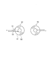
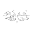
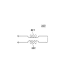
図1は、本発明の第1実施形態の非接触式電力伝送装置1に使用される電磁誘導用コイル20,31である給電コイル20及び受電コイル31の平面図を示し、図2は、給電コイル20と受電コイル31とが相互に対向された状態を側方からみた断面図を示している。また、図3は、本発明の第1実施形態にかかる非接触式電力伝送装置1の基本原理を表すブロック図を示し、図4は、その給電装置10が備える共振回路13の等価回路図を示している。
[First Embodiment]
FIG. 1 is a plan view of a
まず、図3及び図4を参照して、非接触式電力伝送装置1の構成について説明する。
First, the configuration of the contactless
非接触式電力伝送装置1は、給電装置10と受電装置30とから構成されている。
The non-contact
給電装置10は、受電装置30に電力を供給する共振回路13と、共振回路13を駆動する駆動回路15と、駆動回路15を制御する制御回路16とを備えている。また、当該給電装置10の駆動に必要な電圧を印加するために、外部から供給される交流電圧を整流して所定の直流電圧を生成するAC/DC変換回路11と、駆動回路15にパルス波を印加するためのパルス波発信装置12とを備えている。
The
AC/DC変換回路11には、例えば、電源ケーブルを介して、家庭用AC電源(AC100V〜240V))が供給される。そして、このAC/DC変換回路11は、供給された家庭用交流電圧を所定の直流電圧に変換し、変換した直流電圧を出力する。なお、このAC/DC変換回路11は、変換した直流電圧を、給電装置10が備える図示しない別回路(例えば、外部機器との通信を行う通信制御回路)に出力し、当該別回路を駆動している。
The AC /
パルス波発信装置12には、AC/DC変換回路11から出力された直流電圧が入力される。そして、パルス波発信装置12は、例えば0V−5Vのパルス波を駆動回路15に出力している。ただし、パルス波発信器12により発信されるパルス波のハイレベルにおける電圧は、仕様に応じ適切な値を発信すればよい。
The DC voltage output from the AC /
共振回路13は、一次側コンデンサ14及び給電コイル20を備えたLC直列回路から構成されており、駆動回路15からの出力に基づいて電磁誘導を生じさせ、受電装置30に設けられた受電コイル31に交流電圧を発生させている。この実施形態では、給電コイル20は二つの平面スパイラルコイル21,22が並列接続されて構成されている。なお、図4は、共振回路13として、LCR直列回路を示しているが、図4に示した符号17はキャパシタを駆動する回路の内部抵抗Rpを表している。
The
駆動回路15には、パルス波発信装置12から発信されたパルス波が入力される。この駆動回路15は、制御回路16によって入力された交流電圧を共振回路13に出力するか否かの制御が行われつつ共振回路13へパルス波を出力している。
A pulse wave transmitted from the pulse
そして、制御回路16は、図示しない制御部の制御に基づいて駆動回路15を駆動させるか否かを制御している。
The
一方、受電装置30は、給電装置10の共振回路13の駆動に伴う電磁誘導により起電力が生ずる受電コイル31と、受電コイル31に発生した起電力の電力変換を行う電力変換回路32とを備えている。なお、この受電装置30の回路に生じる負荷抵抗を符号33で表している。
On the other hand, the
受電コイル31は、給電コイル20に印加された電圧に伴ってこの受電コイル31の両端に電圧を発生させて誘導電流を発生させ、電力変換回路32に出力している。
The
電力変換回路32は、整流回路を有し、入力された交流電流を直流電流に変換して図示しない充電器または電子機器に出力するようになっている。なお、例えば、整流回路は、ダイオードブリッジ回路によって構成されている。
The
次に、図1及び図2を参照して電磁誘導用コイル20,31の構成を説明する。 Next, the configuration of the electromagnetic induction coils 20 and 31 will be described with reference to FIGS.
給電コイル20は、外側に配置された第1給電コイル21と、内側に配置された第2給電コイル22から構成されている。これら第1給電コイル21及び第2給電コイル22はいずれも平坦な平面スパイラルコイルにより構成されている。
The feeding
第1給電コイル21は、その素線21aが渦巻状に巻かれてドーナツ状に形成されており、その中央に空間部が設けられ、この空間部がコイル収容部25として構成されている。一方、第2給電コイル22も、その素線22aが渦巻状に巻かれて形成されており、その中心には素線22aの存在しない空間部が設けられている。即ち、第2給電コイル22は空芯平面スパイラルコイルである。そして、第2給電コイル22は、第1給電コイル21に形成されたコイル収容部25の内側に収容されている。コイル収容部25に第2給電コイル22が収容された状態において、給電コイル20の厚み方向に関し、第1給電コイル21から第2給電コイル22が突出することのないように第1給電コイル21及び第2給電コイル22は一平面をなしている。なお、第2給電コイル22を第1給電コイル21のコイル収容部25に収容する際に、第1給電コイル21の内縁と、第2給電コイル22の外縁との間に少なくとも1mmの隙間を形成するとよい。
The
これら第1給電コイル21と第2給電コイル22とは、両者が同一方向に磁束を形成させるように並列接続されている。例えば、第1給電コイル21及び第2給電コイル22の双方を時計回りに外から内に巻いて形成した場合、第1給電コイル21及び第2給電コイル22の外周側の素線21a,22a同士を接続すると共に、第1給電コイル21及び第2給電コイル22の内周側の素線21a,22a同士を接続し、両者を並列接続する。
The
また、第1給電コイル21のインダクタンスの値と、第2給電コイル22のインダクタンスの値は略同値となるように、第1給電コイル21及び第2給電コイル22は形成されている。これにより、給電コイル20に電流を流した際に、第1給電コイル21と第2給電のいずれかにのみ流れてしまうことを防止し、第1給電コイル21と第2給電の双方に電流が流れることを確保している。
The
一方、受電コイル31も、素線31aを渦巻状に巻いて形成した平面スパイラルコイルから構成されている。この受電コイル31は、その外径が第2給電コイル22の外径とほぼ同寸に形成されると共に、その中心部には素線31aの存在しない空間部が形成されている。即ち、給電コイル20は空芯平面スパイラルコイルとして構成され、その外径及び内径はともに第2給電コイル22とほぼ同寸に形成されている。
On the other hand, the
以上の給電装置10及び受電装置30を用いて給電装置10から受電装置30に電力伝送する際には、図2に示すように、給電コイル20と受電コイル31とを相互に対向させて、両者の間で電磁誘導を生じさせることで行われる。給電コイル20と受電コイル31とを対向させる際には、給電コイル20と受電コイル31との中心をできるだけ一致させる。
When power is transmitted from the
次に、本実施形態にかかる非接触式電力伝送装置1における電力伝送の基本原理について説明する。
Next, the basic principle of power transmission in the contactless
この非接触式電力伝送装置1では、電磁誘導を利用して給電装置10から受電装置30に電力を伝送している。即ち、受電装置30が備える受電コイル31の起電力は、給電コイル20により形成される磁束が受電コイル31を鎖交する磁束の大きさに影響を受ける。そして、給電コイル20が形成する磁束の大きさは、給電コイル20を流れる電流により決定される。このことから、給電コイル20に流れる電流を大きく、発生する電圧を低下させることが、伝送効率を向上させて受電コイル31の起電力を向上させるためには重要である。
In the non-contact
この点に関し、本実施形態委かかる非接触式電力伝送装置1では、給電装置10が共振回路13を備えていることから、共振回路13において、給電コイル20と一時側コンデンサ14と間で共振現象を起こさせている。これにより、デジタル信号が正弦波形に変換され、かつ、共振状態においては、回路のインピーダンスが最小となり、得られる電流が最大となる。このような給電装置10の共振を利用して最大限の電力を受電装置30に伝送させている。
In this regard, in the contactless
また、電磁誘導を利用する場合、受電装置30が備える受電コイル31の電力は、電圧の2乗に比例し、抵抗値に反比例をする。このため、受電コイル31に発生する電圧の低下を防止することも重要である。より詳細には、受電コイル電圧の負荷抵抗RLの依存性について、負荷抵抗RLが低い領域では受電コイル電圧を上昇させる一方で、負荷抵抗RLの高い領域では受電コイル電圧を低下させることで、受電コイル電圧を負荷抵抗RL変化に対し一定に保たれることがきわめて重要となる。
When electromagnetic induction is used, the power of the
以上の点について、給電装置10が共振回路13を備えている。共振回路13では、コイルに発生する電圧は、Q値に影響を受け、Q値が定まればコイルに生じる電圧を決定することから、Q値に着目する。なお、Q値とは共振の度合いや鋭さを表す値であり、Qの値が低いということは共振を素早くコントロールし、素早くとめることができていることを示し、逆にQ値が高いということは共振が長く続いているということである。このQ値は次の式(1)で表される。
With respect to the above points, the
Q=1/R×√(L/C)・・・(1) Q = 1 / R × √ (L / C) (1)
式(1)から明らかなように、Q値は、抵抗値Rと、キャパシタンスCの平方根の値に反比例し、インダクタンスLの平方根の値に比例する。Q値を小さくするには、抵抗値Rを大きくするか、キャパシタンスCを大きくするか、又はインダクタンスLを小さくすることが必要である。 As apparent from the equation (1), the Q value is inversely proportional to the resistance value R and the square root value of the capacitance C, and is proportional to the square root value of the inductance L. In order to reduce the Q value, it is necessary to increase the resistance value R, increase the capacitance C, or decrease the inductance L.
この点に関し、仮に抵抗値Rを大きくすると発熱し、キャパシタンスCを大きくすれば共振周波数が低下するという不都合がある。このため、インダクタンスLをさげることが最適である。 In this regard, if the resistance value R is increased, heat is generated, and if the capacitance C is increased, the resonance frequency is lowered. For this reason, it is optimal to reduce the inductance L.
ここで、本実施形態の給電コイル20のように第1給電コイル21の内側に第2給電コイル22を配置した場合における合成インダクタンスを求める。第1給電コイル21と第2給電コイル22の合成インダクタンスをLL、第1給電コイル21のインダクタンスをLp1,第2給電コイル22のインダクタンスをLp2とする。合成インダクタンスLLをLp1とLp2とで表すと次の式(2)で表すことができる。
Here, the combined inductance in the case where the
LL=Lp1×Lp2/(Lp1+Lp2)・・・(2) LL = Lp1 × Lp2 / (Lp1 + Lp2) (2)
いま、第2給電コイル22のインダクタンスLp2の値が第1給電コイル21のインダクタンスLp1と同値であるとすれば、合成インダクタンスLLは、式(3)のように表すことができる。
Now, assuming that the value of the inductance Lp2 of the
LL=Lp1/2・・・(3) LL = Lp1 / 2 (3)
このように、本実施形態にかかる給電装置10の給電コイル20によれば、一般的なシングルタイプの平面スパイラルコイルと比較してインダクタンスの値を約半分に低下させることができることになる。
Thus, according to the
このように、給電コイル20のインダクタンスの値を低下させるとで、給電装置10が備える共振回路13のQ値を下げることができる。そして、給電装置10のQ値を下げることで、受電装置30では、受電コイル31の電圧は、負荷抵抗RLの変化に対し、より一定に維持され、使用したい実用領域における電圧を上昇せしめ、受電コイル電圧の負荷抵抗値の変化に対応する変化を減少させて電圧の変化を平坦にして、負荷抵抗に依存する領域を広くすることができる。
Thus, by reducing the inductance value of the
既述のように、受電装置30は、電力変換回路32を具備している。この電力変換回路32には種々のICが使用される。一般的なシングルタイプの平面スパイラルコイルを使用していた場合には、電圧の変化が大きいかったため、耐圧領域の広いICを選択しなければならなかったが、電圧の変化が減少して平坦にされることにより、耐圧領域の狭いICを選択する事が可能となる。
As described above, the
以上、給電コイルとして2つの平面スパイラルコイルを使用した2重コイルの場合を例に説明したが、これに限定されるものではなく、平面スパイラルコイルを3つ以上使用した多重コイルを使用して給電コイルを形成してもよい。 As described above, the case of a double coil using two planar spiral coils as an example of the feeding coil has been described as an example. However, the present invention is not limited to this, and power is supplied using a multiple coil using three or more planar spiral coils. A coil may be formed.
図5は、3つの平面スパイラルコイルを使用して給電コイル40を形成したものを示している。
FIG. 5 shows a structure in which the feeding
この給電コイル40は、中央に空間部がそれぞれ形成された平面スパイラルコイルが用いられている。各平面スパイラルコイルは、相互の内縁寸法及び外縁寸法が順次小さくなるように形成され、外側から順に第1給電コイル41、第2給電コイル、第3給電コイルのように配置されている。
The
具体的には、第2給電コイル42の外径は、第1給電コイル41の内径より小さく形成され、第3給電コイル43の外径は第2給電コイル42の内径より小さく形成されている。そして、第1〜第3の給電コイル41,42,43は、第2給電コイル42が第1給電コイル41の中央に形成された空間部の内側に配置され、さらに、第3給電コイル43は、第2給電コイル42の中央に形成された空間部の内側に配置されている。この場合においても、第1給電コイル41の内縁と第2給電コイル42の外縁との間、及び第2給電コイル42の内縁と第3給電コイル42の外縁との間にはそれぞれ1mm以上の隙間を形成するとよい。
Specifically, the outer diameter of the
また、第1〜第3の給電コイル41,42,43は、給電コイル40の厚み方向に関し、相互に突出することなく平面状をなしている。さらに、第1〜第3の給電コイル41,42,43は、それぞれの最外周に位置する素線同士が接続されると共に、最内周に位置する素線同士が接続されて並列接続されている。
The first to third power supply coils 41, 42, and 43 have a planar shape without protruding from each other in the thickness direction of the
なお、このように複数の平面スパイラルコイルで給電コイルを形成した場合においても、最も内側に配置された平面スパイラルコイルの外径は、受電コイルの外径と略同寸に形成するよい。 Even when the feeding coil is formed of a plurality of planar spiral coils as described above, the outer diameter of the innermost planar spiral coil may be formed to be approximately the same as the outer diameter of the power receiving coil.
以上、平面スパイラルコイルの外形が円形であるものを例に説明したが、平面スパイラルコイルの外形は三角形、四角形、五角形、六角形などの多角形に形成してもよい。 As described above, the planar spiral coil has a circular outer shape as an example. However, the planar spiral coil may be formed in a polygonal shape such as a triangle, a quadrangle, a pentagon, or a hexagon.
図6は、六角形に形成した電磁誘導コイルを示している。 FIG. 6 shows an electromagnetic induction coil formed in a hexagon.
給電コイル45は、外寸が大きく形成された第1給電コイル46と外寸の小さく形成された第2給電コイル47とから構成されている。第1給電コイル46は、その外形が六角形となるようにその素線が渦巻状に巻かれ、中央には素線の存在しない空間部が形成されている。同様に、第2給電コイル47も、その中央に空間部が形成されるようにして、外形が六角形をなすように渦巻状に素線が巻かれて形成されている。そして、第1給電コイル46を構成する素線と第2給電コイル47を構成する素線とは、同一軸が中心となるように巻かれて構成されるように、第1給電コイル46の中央に形成された空間部の内側に第2給電コイル47が配置されて給電コイル45は構成される。
The feeding
なお、この給電コイル45についても、第1給電コイル46と第2給電コイルとが、厚み方向に関して相互に突出されることなく平面状をなしている。また、第1給電コイル46の内縁と、第2給電コイル47の外縁との間には1mm以上の隙間を形成するとよい。
In addition, also about this feeding
一方、受電コイル48も、その外形が六角形をなすようにして素線が渦巻状に巻かれて構成されている。この受電コイル48は、その外縁寸法及び内縁寸法が給電コイル45のうち、内側に配置されている第2給電コイル47の外縁寸法及び内縁寸法とほぼ同寸に形成されている。
On the other hand, the
[第2実施形態]
次に、図7及び図8を参照して、本発明の第2実施形態について説明する。
[Second Embodiment]
Next, a second embodiment of the present invention will be described with reference to FIGS.
既述のように、電磁誘導を利用して電力伝送するには、給電装置10が備える共振回路13のQ値を下げることが効果的である。この第2実施形態においても、Q値を下げるために採用した構成である。なお、この第2実施形態は、電磁誘導用コイル50,60の構成のみが第1実施形態にかかる非接触式電力伝送装置1とは異なり、その他の給電装置10の構成及び受電装置30の構成は同じであるので、ここでは電磁誘導用コイル50,60についてのみ説明する。
As described above, in order to transmit power using electromagnetic induction, it is effective to lower the Q value of the
この電磁誘導用コイル50,60をなす給電コイル50も、2個の平面スパイラルコイル51,52から構成されている。給電コイル50は、2個の平面スパイラルコイル51,52を構成するそれぞれの素線51a,52aが並列に並べられ、並べられた状態で渦巻状に巻かれるようにして構成されている。各素線51a,52aが並列に並べられた状態で渦巻状に巻かれることにより、給電コイル50を半径方向に見た場合、各平面スパイラルコイル51,52を構成するそれぞれの素線51a,52aは交互に並べられる。そして、形成された給電コイル50は、一平面を構成している。この給電コイル50についても、二つの平面スパイラルコイル51,52は、それぞれの最外周の素線51a,52a同士が接続されると共に、最内周の素線51a,52a同士が接続されて並列に接続される。なお、この給電コイル50においても、その中心部分には、素線51a,52aが存在しない空間部が設けられ、空芯平面スパイラルコイルとなされている。
The
なお、2個の平面スパイラルコイル51,52は、素線径及び素線長がほぼ同寸の同一材料の素線によって形成されており、両者のインダクタンス値は略同値となされている。
The two planar spiral coils 51 and 52 are formed of strands of the same material whose strand diameter and strand length are approximately the same, and the inductance values of the two
一方、受電コイル60は、1本の素線60aが渦巻状に巻かれ構成された平面スパイラルコイルである。その外径は給電コイル50の外径とほぼ同寸に形成されている。また、中心部分には素線60aの存在しない空間部が形成されており、空芯平面スパイラルコイルとなされている。その中心部分に形成される空間部の内径も、給電コイル50の中央部分に形成された空間部の内径とほぼ同寸に形成されている。
On the other hand, the
これら給電コイル50と受電コイル60を使用して電力伝送を行う際には、図8に示すように、給電コイル50と受電コイル60とを対向させる。この際、両者の中心がほぼ一致されるように配置する。
When power transmission is performed using the
次に、本実施形態にかかる電磁誘導用コイル50,60の基本的な考え方について説明する。 Next, the basic concept of the electromagnetic induction coils 50 and 60 according to the present embodiment will be described.
この実施形態においても、インダクタンス値を下げることでQ値を下げて電力伝送の効率を向上させている点で第1実施形態にかかる非接触式電力伝送装置1と基本思想は同様である。この給電コイル50では、インダクタンス値を下げるために、平面スパイラルコイル51,52の巻数を少なくしている。もっとも、単純に巻数を少なくしたのでは、給電コイル50の外寸が小さくなる。そうすると、給電コイル50と受電コイル60との間で磁束の漏れが生じてしまう。
Also in this embodiment, the basic idea is the same as that of the non-contact
このため、給電コイル50の巻数を少なくしつつ、外寸を維持するために、2個の平面スパイラルコイル51,52を構成するそれぞれの素線51a,52aを並列に並べ、並べられた状態で素線51a,52aを渦巻状に巻いて給電コイル50を構成しているのである。
For this reason, in order to maintain the outer dimension while reducing the number of turns of the feeding
この第2実施形態に関しても、給電装置10は、給電コイル50をその構成要素とする共振回路13を備えているため、共振回路13において、給電コイル20とコンデンサ14と間で共振現象を起こさせている。これにより、デジタル信号が正弦波形に変換され、かつ、共振状態においては、回路のインピーダンスが最小となり、得られる電流が最大となる。このような給電装置10の共振を利用して最大限の電力を受電装置30に伝送させている。
Also in the second embodiment, since the
また、給電コイル50を第2実施形態のように形成することで、給電装置10が備える共振回路13のQ値を下げることができ、受電コイル電圧の負荷抵抗RLの依存性について、負荷抵抗RLが低い領域では受電コイル電圧を上昇させる一方で、負荷抵抗RLの高い領域では受電コイル電圧を低下させて、受電コイル電圧を負荷抵抗RL変化に対し一定にすることができる。
In addition, by forming the
なお、第2実施形態についても、給電コイル及び受電コイルの外形は三角形、四角形、五角形、六角形などの多角形に形成してもよい。 Also in the second embodiment, the outer shape of the feeding coil and the receiving coil may be formed in a polygon such as a triangle, a quadrangle, a pentagon, and a hexagon.
[第3実施形態]
次に、図9及び図10を参照して本発明の第3実施形態について説明する。図9は給電コイル70及び受電コイル80の平面図を示し、図10は、対向された給電コイル70及び受電コイル80における、図9のA部におけるA−A断面の拡大図を示したものである。なお、この実施形態においても、電磁誘導用コイル70,80の構成のみが第1実施形態にかかる非接触式電力伝送装置1とは異なり、その他の給電装置10の構成及び受電装置30の構成及び作用は、図3に示したものと同じであるので、電磁誘導用コイル70,80についてのみ説明する。
[Third Embodiment]
Next, a third embodiment of the present invention will be described with reference to FIGS. FIG. 9 is a plan view of the
給電コイル70は、3つの平面スパイラルコイル71,72,73の群から構成されている。この給電コイル70は、各平面スパイラルコイル71,72,73を構成している素線が並列に並べられ、これら3本の素線が一つの中心軸を中心として渦巻状に巻かれ、平面状に形成されている。これら3つの平面スパイラルコイル71,72,73は、その素線径及び素線長が相互に同寸の同一材料の素線により形成されている。このため、3つの平面スパイラルコイルのインダクタンス値は略同値となっている。
The feeding
この給電コイル70について、給電コイル70の最外周を第1周目とした場合、図10に示すように、各周では、外側に平面スパイラルコイル71の素線が位置し、中央に平面スパイラルコイル72の素線が位置し、そして内側に平面スパイラルコイル73の素線が位置している。なお、この図10では外側から数え第n周目から第n+4周目までを示している。
When the outermost periphery of the
そして、この給電コイルで70では、各平面スパイラルコイル71,72,73の最外周及び最内周においてそれぞれの素線の端部に接続端子を設けている。これにより、共振回路13にこれら接続端子を選択して接続するようにして、3つの平面スパイラルコイル71,72,73のうち、いずれか一つのコイルを択一的に選択可能になっており、選択した平面スパイラルコイルにのみ電流を流して電磁誘導に利用する。例えば、図9及び図10に示すように、平面スパイラルコイル72を選択して共振回路13に接続し、他の平面スパイラルコイル71,73は、共振回路13には接続しないことで、平面スパイラルコイル72のみを電磁誘導に利用する。もっとも、選択する平面スパイラルコイルは、他のものを選択しても構わない。
In the feeding
一方、受電コイル80は、一本の素線が渦巻状に巻かれ平面状に形成されている。この受電コイル80は、給電コイル70を構成する3つの平面スパイラルコイル71,72,73の素線と素線径が同寸の素線が使用されて、その外径及び内径が給電コイル70の外径及び内径と略同寸に形成されている。
On the other hand, the
このように、給電コイル70と受電コイル80とを形成した場合、給電コイル70にあっては、電磁誘導に利用される平面スパイラルコイルは、3つのうち1つだけなので、電磁誘導に利用される給電コイル70の平面スパイラルコイルは、その巻数が受電コイル80の巻数の1/3となる。
Thus, when the
この第3実施形態では、給電コイル70において電磁誘導に利用する平面スパイラルコイルの巻数を少なくすることでインダクタンス値を減少させることができ、その結果、Q値を下げている。
In the third embodiment, the inductance value can be reduced by reducing the number of turns of the planar spiral coil used for electromagnetic induction in the
そして、第3実施形態においても、給電装置10は、給電コイル50をその構成要素とする共振回路13を備えているため、共振回路13において、給電コイル20とコンデンサ14と間で共振現象を起こさせている。これにより、デジタル信号が正弦波形に変換され、かつ、共振状態においては、回路のインピーダンスが最小となり、得られる電流が最大となる。このような給電装置10の共振を利用して最大限の電力を受電装置30に伝送させている。
Also in the third embodiment, since the
また、給電装置10が備える共振回路13のQ値を下げることで、受電コイル電圧の負荷抵抗RLの依存性について、負荷抵抗RLが低い領域では受電コイル電圧を上昇させる一方で、負荷抵抗RLの高い領域では受電コイル電圧を低下させて、受電コイル電圧を負荷抵抗RL変化に対し一定にすることができる。
In addition, by reducing the Q value of the
さらに、この第3実施形態においては、給電コイル70において、3つの平面スパイラルコイル71,72,73のうちいずれか一つを利用するため、給電コイル70の内側に位置する素線と外側に位置する素線との間に、いわゆる近接効果が生じることがない。例えば、図10に示すように、平面スパイラルコイル72を選択し、平面スパイラルコイル72にのみ電流を流した場合、平面スパイラルコイル72を構成する素線同士の間には、選択しなかった平面スパイラルコイル71と平面スパイラルコイル73の素線が存在する。このため、平面スパイラルコイル72の素線同士が相互に密着することが無く、近接効果が生じることがないのである。
Further, in the third embodiment, since any one of the three planar spiral coils 71, 72, 73 is used in the
なお、給電コイル70において、選択すべき平面スパイラルコイルの素線に着色したり、あるいは端子部分にビニールチューブ等の目印を付けるなどして、選択すべき平面スパイラルコイルを他の平面スパイラルコイルと区別するための識別手段を設けるとよい。
In the
以上、給電コイルを3つの平面スパイラルコイルの群で構成した場合について説明したが、これには限定されず、2つの平面スパイラルコイルの群で給電コイルを構成したり、4つ以上の平面スパイラルコイルの群で給電コイルを構成してもよい。なお、給電コイルを3つ以外の平面スパイラルコイル群で構成した場合においても、共振回路に接続して電磁誘導に利用するものを択一的に選択する。 As described above, the case where the power feeding coil is configured by a group of three planar spiral coils has been described. However, the present invention is not limited to this, and the power feeding coil is configured by a group of two planar spiral coils, or four or more planar spiral coils. You may comprise a feed coil by the group of. Even when the power feeding coil is constituted by a group of planar spiral coils other than three, one that is connected to the resonance circuit and used for electromagnetic induction is alternatively selected.
このように、給電コイルをN回巻の複数の平面スパイラルコイル群で構成することで、インダクタンスの値を受電コイルのインダンクタンスの値に対し1/Nとすることができる。そして、給電コイルを所望の巻数に形成することで、給電コイルと受電コイルのインダクタンス比を任意に設定することができる。しかも、電磁誘導に利用するコイルをN個の中から選択するように構成することで、電流の流れる素線同士が密着することが無く、近接効果の発生を効果的に防止できる。 In this way, by configuring the power supply coil with a plurality of N-turn planar spiral coil groups, the inductance value can be reduced to 1 / N with respect to the inductance value of the power receiving coil. And the inductance ratio of a feeding coil and a receiving coil can be arbitrarily set by forming a feeding coil in a desired number of turns. In addition, by configuring the coil to be used for electromagnetic induction to be selected from N, the strands through which current flows are not in close contact with each other, and the generation of the proximity effect can be effectively prevented.
なお、この第3実施形態についても、給電コイル及び受電コイルの外形は三角形、四角形、五角形、六角形などの多角形に形成してもよい。 In the third embodiment, the outer shape of the feeding coil and the receiving coil may be formed in a polygon such as a triangle, a quadrangle, a pentagon, and a hexagon.
[第4実施形態]
次に図11及び図12を参照して本発明の第4実施形態について説明する。図11は、第4実施形態にかかる非接触式電力伝送装置に使用する給電コイル90と受電コイル100の平面図を示し、図12は、対向された給電コイル90と受電コイル100とに関し、図11のB部のB−B断面に着いての拡大部分断面図を示したものである。
[Fourth Embodiment]
Next, a fourth embodiment of the present invention will be described with reference to FIGS. FIG. 11 is a plan view of the
給電コイル90は、4つの平面スパイラルコイル91,92,93,94の群により構成されている。4つの平面スパイラルコイル91,92,93,94の群は、並列に並べられた4本の素線が同一軸を中心にして渦巻状に巻かれるようにして平面状に形成される。図12は、給電コイル90を構成している各平面スパイラルコイル91,92,93,94について、外側から第n周目の素線と第n+1周目の素線の配列を示している。各周において、各平面スパイラルコイル91,92,93,94の素線は、外側から平面スパイラルコイル91の素線、平面スパイラルコイル92の素線、平面スパイラルコイル93の素線、平面スパイラルコイル94の素線の順に配列されている。
The feeding
なお、給電コイル90を構成している各平面スパイラルコイル91,92,93,94は、その素線は、同寸の素線径のものが使用されている。また、各平面スパイラルコイル91,92,93,94の素線長は略同寸に形成されている。このため、各平面スパイラルコイル91,92,93,94のインダクタンス値は略同値となっている。
The planar spiral coils 91, 92, 93, 94 constituting the
これに対し、受電コイルは、1本の素線が渦巻状に巻かれ、かつ、平面状に形成されることで構成されている。給電コイルの外径は受電コイルの外径と略同寸に形成されているため、給電コイルを構成する各平面コイルは、受電コイルの巻数の1/4の巻数である。 On the other hand, the power receiving coil is configured by a single wire wound in a spiral shape and formed in a planar shape. Since the outer diameter of the power feeding coil is formed to be approximately the same as the outer diameter of the power receiving coil, each planar coil constituting the power feeding coil is ¼ the number of turns of the power receiving coil.
そして、この給電コイルで90についても、各平面スパイラルコイル91,92,93,94の最外周及び最内周においてそれぞれの素線の端部に接続端子を設けている。これにより、共振回路13にこれら接続端子を選択して接続するようにして、4つの平面スパイラルコイル91,92,93,94の中から所望のコイルを選択可能になっている。この給電コイル90については、給電コイル90を構成する4つの平面コイル群の中から、素線が最も外側に位置するように巻かれた平面スパイラルコイル91と、コイル群の中から、外側から3番目に位置する平面スパイラルコイル93とが選択され、この2つの平面スパイラルコイル91,93が共振回路に接続されて電磁誘導に利用される。2つの平面スパイラルコイル91,93を選択することで、第n周目においては、平面スパイラルコイル91と、平面スパイラルコイル93との間には、平面スパイラルコイル92が介在し、第n周目と第n+1周目においては、平面スパイラルコイル91と、平面スパイラルコイル93との間には、平面スパイラルコイル94が介在することになる。
And also with respect to 90 in this feeding coil, connection terminals are provided at the ends of the respective strands at the outermost and innermost circumferences of the respective planar spiral coils 91, 92, 93, 94. Thus, a desired coil can be selected from the four planar spiral coils 91, 92, 93, 94 by selecting and connecting these connection terminals to the
このように、この給電コイル90では、電磁誘導に利用するために選択された平面スパイラルコイル同士の間には、選択されない平面スパイラルコイルが介在し、電磁誘導に利用される平面スパイラルコイルの素線同士が相互に密着しあわないように構成される。
As described above, in the
そして、選択された2つの平面スパイラルコイル91,93は、それぞれの最外周を構成する素線同士が接続されると共に、最内周の素線同士が接続されて両者が並列接続される。なお、選択された2つの平面スパイラルコイル91,93の素線には、他の平面スパイラルコイル92,94と区別するために、色を付けたり、端子部分にビニールチューブ等の目印を付けるなどして識別可能にされる。 The two selected planar spiral coils 91 and 93 are connected to each other in the outermost periphery, and are connected in parallel with the innermost strands connected to each other. The strands of the two selected planar spiral coils 91 and 93 are colored to distinguish them from the other planar spiral coils 92 and 94, or a mark such as a vinyl tube is attached to the terminal portion. Can be identified.
以上のように構成することで、この第4実施形態でも、給電コイル90のインダクタンス値を減少させることができ、その結果、Q値を下げている。そして、給電コイル90を備えた給電装置10の共振回路13では、給電コイル20とコンデンサ14と間で共振現象が生じ、デジタル信号が正弦波形に変換され、かつ、共振状態においては、回路のインピーダンスが最小となり、得られる電流が最大となる。このような給電装置10の共振を利用して最大限の電力を受電装置30に伝送させている。
By configuring as described above, also in the fourth embodiment, the inductance value of the feeding
また、給電装置10が備える共振回路13のQ値を下げることで、受電コイル電圧の負荷抵抗RLの依存性について、負荷抵抗RLが低い領域では受電コイル電圧を上昇させる一方で、負荷抵抗RLの高い領域では受電コイル電圧を低下させて、受電コイル電圧を負荷抵抗RL変化に対し一定にすることができる。
In addition, by reducing the Q value of the
さらに、給電コイル90において、電磁誘導に利用するために選択される平面スパイラルコイルは、選択されない平面スパイラルコイルを間に介在させているため、電磁誘導に利用される平面スパイラルコイルの素線同士が相互に密着せず、近接効果が生じることがない。
Furthermore, since the planar spiral coil selected for use in electromagnetic induction in the
以上、平面スパイラルコイル91,93を選択した場合について説明したが、平面スパイラルコイル92,94を選択して給電コイル90を構成してもよい。この場合、選択した平面スパイラルコイル92,94の素線の間には、選択しなかった平面スパイラルコイル91,93の素線が介在される。このため、近接効果の発生を防止できる。
Although the case where the planar spiral coils 91 and 93 are selected has been described above, the feeding
また、給電コイルが4つの平面スパイラルコイルの場合を例に説明したが、5つ以上の平面スパイラルコイルの群で給電コイルを構成してもよい。この場合にも、電磁誘導に利用するために選択する平面スパイラルコイルの間には、選択されない平面スパイラルコイルの素線が介在されるようにして給電コイルを構成する。 Moreover, although the case where the feeding coil is four planar spiral coils has been described as an example, the feeding coil may be configured by a group of five or more planar spiral coils. Also in this case, the feeding coil is configured such that the element wires of the unselected planar spiral coil are interposed between the planar spiral coils selected for use in electromagnetic induction.
この第4実施形態においても、給電コイルを構成する平面スパイラルコイルの数を変更して、各平面スパイラルコイルの巻数と受電コイルの巻数との比率を変化させることで、給電コイルのインダクタンスと受電コイルのインダクタンスの比率を自在に設定できる。 Also in the fourth embodiment, by changing the number of planar spiral coils constituting the feeding coil and changing the ratio between the number of turns of each planar spiral coil and the number of windings of the receiving coil, the inductance of the feeding coil and the receiving coil The inductance ratio can be set freely.
なお、この第4実施形態においても、給電コイル及び受電コイルの外形は三角形、四角形、五角形、六角形などの多角形に形成してもよい。 Also in the fourth embodiment, the outer shape of the feeding coil and the receiving coil may be formed in a polygon such as a triangle, a quadrangle, a pentagon, and a hexagon.
[第5実施形態]
次に図13及び図14を参照して本発明の第5実施形態について説明する。図13は、給電コイル110及び受電コイル120の平面図を示し、図14は、対向された給電コイル110及び受電コイル120における、図13のC部におけるC−C断面の拡大図を示したものである。なお、この実施形態においても、電磁誘導用コイル70,80の構成のみが第1実施形態にかかる非接触式電力伝送装置1とは異なり、その他の給電装置10の構成及び受電装置30の構成及び作用は、図3に示したものと同じであるので、電磁誘導用コイル110,120についてのみ説明する。
[Fifth Embodiment]
Next, a fifth embodiment of the present invention will be described with reference to FIGS. FIG. 13 is a plan view of the
給電コイル110は、3つの平面スパイラルコイル111,112,113の群から構成されている。この給電コイル110は、各平面スパイラルコイル111,112,113を構成する素線が並列に並べられ、これら3本の素線が一つの中心軸を中心として渦巻状に巻かれるようにして、平面状に形成されている。これら3つの平面スパイラルコイル111,112,113は、その素線径及び素線長が相互に同寸で、かつ、同一材料の素線により形成されている。このため、3つの平面スパイラルコイル111,112,113のインダクタンス値は略同値となっている。
The feeding
この給電コイル110は、その最外周を第1周目とした場合、図14に示すように、各周では、外側に平面スパイラルコイル111の素線が位置し、中央に平面スパイラルコイル112の素線が位置し、そして内側に平面スパイラルコイル113の素線が位置している。なお、この図14では外側第n周目と第n+1周目を示している。
As shown in FIG. 14, when the outermost circumference of the
そして、この給電コイル110についても、各素線の端部には端子が設けられ、3つの平面スパイラルコイル111,112,113のうち、いずれか一つのコイルを択一的に選択可能になっており、選択した平面スパイラルコイルにのみ電流を流して電磁誘導に利用する。例えば、図13及び図14に示すように、平面スパイラルコイル112を選択して共振回路13に接続し、他の平面スパイラルコイル111,113は、共振回路には接続しないことで、平面スパイラルコイル112のみを電磁誘導に利用する。もっとも、選択する平面スパイラルコイルは、他のものを選択しても構わない。
The feeding
一方、受電コイル120は、2つの平面スパイラルコイル121,122から構成されている。受電コイル120は、並列に並べられた2本の素線が渦巻状に巻かれ平面状に形成されている。この受電コイル120は、給電コイル110を構成する3つの平面スパイラルコイル111,112,113の素線と素線径が同寸の素線が使用されて、その外径及び内径が給電コイル110の外径及び内径と略同寸に形成されている。そして、平面スパイラルコイル121,122の各素線の端部には端子が設けられており、そのいずれかを回路に接続可能となっていて、2つの平面スパイラルコイル121,122のうち一方のみが選択されて電磁誘導に利用される。
On the other hand, the
この第5実施形態のように、給電コイル110と受電コイル120とを形成した場合、電磁誘導に利用される平面スパイラルコイルのインダクタンス比は、2:3となり、給電コイル110において電磁誘導に利用する平面スパイラルコイルのインダクタンス値を小さくし、その結果、Q値を下げている。
When the
そして、第5実施形態においても、給電装置10の共振回路13において、給電コイル20とコンデンサ14と間で共振現象が生じ、印加されたデジタル信号が正弦波形に変換される。また、共振状態においては、回路のインピーダンスが最小となり、得られる電流が最大となる。このような給電装置10の共振を利用して最大限の電力を受電装置30に伝送させている。
Also in the fifth embodiment, in the
また、給電装置10が備える共振回路13のQ値を下げることで、受電コイル電圧の負荷抵抗RLの依存性について、負荷抵抗RLが低い領域では受電コイル電圧を上昇させる一方で、負荷抵抗RLの高い領域では受電コイル電圧を低下させて、受電コイル電圧を負荷抵抗RL変化に対し一定にすることができる。
In addition, by reducing the Q value of the
さらに、この第5実施形態においては、給電コイル110及び受電コイル120のいずれついても、電磁誘導に利用される平面スパイラルコイルの素線同士の間には、選択しない平面スパイラルコイルの素線が介在するため、近接効果の発生を防止できる。
Furthermore, in this fifth embodiment, any of the wires of the planar spiral coil that is not selected is interposed between the strands of the planar spiral coil used for electromagnetic induction in any of the feeding
なお、給電コイル110及び受電コイル120のいずれについても、選択すべき平面スパイラルコイルの素線に着色したり、あるいは端子部分にビニールチューブ等の目印を付けるなどして、選択すべき平面スパイラルコイルを他の平面スパイラルコイルと区別するための識別手段を設けるとよい。
For both the
以上、給電コイルを3つの平面スパイラルコイルの群で構成し、受電コイルを2つの平面スパイラルコイルで構成した場合について説明したが、これには限定されず、給電コイルを構成する平面スパイラルコイルの数を、受電コイルを構成する平面スパイラルコイルの数より多くして、給電コイルの巻数を受電コイルの巻数よりも少なくするのであれば、給電コイル及び受電コイルを他の数の平面スパイラルコイルで構成してもよい。 The case where the power feeding coil is configured by a group of three planar spiral coils and the power receiving coil is configured by two planar spiral coils has been described above, but is not limited thereto, and the number of planar spiral coils constituting the power feeding coil is described. If the number of turns of the power feeding coil is made smaller than the number of turns of the power receiving coil, the power feeding coil and the power receiving coil are composed of other numbers of planar spiral coils. May be.
このように、給電コイルをN回巻の複数の平面スパイラルコイル群で構成する一方で、受電コイルをM回巻の複数の平面スパイラルコイル群で構成し、その巻数比をN:M(ただし、N<M)とすれば、これに対応して給電コイルのインダクタンスの値と受電コイルのインダンクタンスの値との比率をN:M(ただし、N<M)と自在に設定することが可能となる。 In this way, the power supply coil is composed of a plurality of N-turn planar spiral coil groups, while the power receiving coil is comprised of a plurality of M-turn planar spiral coil groups, and the turns ratio is N: M (however, If N <M), the ratio between the inductance value of the feeding coil and the inductance value of the receiving coil can be set to N: M (where N <M). It becomes.
なお、給電コイルと受電コイルのインダクタンス比を自在に変更可能とする場合、図15及び図16に示すように給電コイル及び受電コイルを設けてもよい。 When the inductance ratio between the power feeding coil and the power receiving coil can be freely changed, a power feeding coil and a power receiving coil may be provided as shown in FIGS.
図15及び図16は、第5実施形態における別の実施例を示したものである。図15は給電コイル130及び受電コイル140の平面図を示し、図16は、対向する給電コイル130及び受電コイル140における図15のD部のD−D断面の拡大図を示したものである。
15 and 16 show another example in the fifth embodiment. FIG. 15 is a plan view of the
給電コイル130は、第3実施形態の給電コイル90と同様の構成からなり、4つの平面スパイラルコイル131,132,133,134の群により構成されている。4つの平面スパイラルコイル131,132,133,134の群は、並列に並べられた4本の素線が同一軸を中心にして渦巻状に巻かれるようにして平面状に形成される。図16は、給電コイル130を構成している各平面スパイラルコイル131,132,133,134について、外側から第n周目の素線と第n+1周目の素線の配列を示している。各周において、各平面スパイラルコイル131,132,133,134の素線は、外側から平面スパイラルコイル131の素線、平面スパイラルコイル132の素線、平面スパイラルコイル133の素線、平面スパイラルコイル134の素線の順に配列されている。
The
なお、各平面スパイラルコイル131,132,133,134は、素線径及び素線長が略同寸の同一材料の素線から形成されており、各平面スパイラルコイル131,132,133,134のインダクタンス値は略同値となされている。 In addition, each planar spiral coil 131,132,133,134 is formed from the strand of the same material whose strand diameter and strand length are substantially the same dimension, and each planar spiral coil 131,132,133,134 is The inductance value is substantially the same value.
一方、受電コイル140は、2つの平面スパイラルコイル141,142から構成されている。受電コイル140は、並列に並べられた2本の素線が渦巻状に巻かれ平面状に形成されている。この受電コイル140は、給電コイル130を構成する4つの平面スパイラルコイル131,132,133,134の素線と素線径が同寸の素線が使用されて、その外径及び内径が給電コイル130の外径及び内径と略同寸に形成されている。
On the other hand, the
この実施例における給電コイル130では、4つの平面スパイラルコイル131,132,133,134のうち2つの平面スパイラルコイル131,133が選択され、選択された2つの平面スパイラルコイル131,133は、それぞれの最外周に位置する素線同士が接続されると共に、最内周の素線同士が接続されて並列接続される。そして、2つの平面スパイラルコイル131,133が共振回路13に接続されて電磁誘導に利用される。このため、図16に示すように、選択された平面スパイラルコイル13,133の素線の間には、選択されなかった平面スパイラルコイル132,134の素線が介在する。
In the
一方、受電コイル140では、2つの平面スパイラルコイル141,142のうち、平面スパイラルコイル141のみが選択されて電磁誘導に利用される。図16は、受電コイル140を構成する平面スパイラルコイル141,142の素線について、外側から第m周目〜第m+4周目までを示しているが、この図16に示すように、電磁誘導に利用される平面スパイラルコイル141の素線同士の間には、選択されなかった平面スパイラルコイル142の素線が介在する。
On the other hand, in the
この実施例のように電磁誘導用コイルである給電コイル130及び1受電コイル140を構成した場合も、給電コイル130の巻数が受電コイル140の巻数よりも少ないため、給電コイルのインダクタンスの値を小さくすることができ、これによりQ値を小さくできる。
Even when the
そして、この場合においても、給電コイルを所望の数の平面スパイラルコイル群で構成すると共に、受電コイルを所望の数の平面スパイラルコイルの群で構成することで、給電コイルの巻数と受電コイルの巻数とを自在に設定でき、その結果、給電コイルのインダクタンスと受電コイルのインダクタンスの比率を所望の値に事由に設定することが可能となる。ただし、この場合においても、給電コイルの巻数Nを受電コイルの巻数Mよりも小さくすることが必要である。 Even in this case, the power supply coil is configured by a desired number of planar spiral coil groups, and the power reception coil is configured by a desired number of planar spiral coil groups. As a result, the ratio between the inductance of the power feeding coil and the inductance of the power receiving coil can be set to a desired value. However, even in this case, it is necessary to make the number N of turns of the feeding coil smaller than the number M of turns of the receiving coil.
なお、この第5実施形態についても、給電コイル及び受電コイルの外形は三角形、四角形、五角形、六角形などの多角形に形成してもよい。 In the fifth embodiment as well, the outer shape of the feeding coil and the receiving coil may be formed in a polygon such as a triangle, a quadrangle, a pentagon, and a hexagon.
[第6実施形態]
次に、図17を参照して、本発明の第6実施形態について説明する。図17は、第6実施形態にかかる非接触式電力伝送装置に使用される給電コイル150と受電コイル160の平面図を示している。
[Sixth Embodiment]
Next, a sixth embodiment of the present invention will be described with reference to FIG. FIG. 17 is a plan view of the
給電コイル150は、外側に配置されたドーナツ状の第1給電コイル151と、第1給電コイル151の内側に配置された第2給電コイル152とから構成され、さらに、第2給電コイル152は、2つの平面スパイラルコイル153,154の群により構成されている。即ち、既述の第1実施形態にかかる給電コイル20と第2実施形態にかかる給電コイル50とを組み合わせたような構成である。
The feeding
第1給電コイル151は、素線を渦巻状に巻いて平坦なドーナツ状に形成したものであり、その中央には素線の存在しない空間部が形成されている。そして、第2給電コイル152は、第1給電コイル151の中央に形成された空間部の内側に配置されている。この2個の平面スパイラルコイル153,154の群により構成された第2給電コイル152は、並列に並べられた2本の素線が同一軸を中心として渦巻状に巻かれるようにして形成されている。そして、第1給電コイル151及び第2給電コイル152は、さらに同一の軸が中心となるように配置されている。
The
このようにして構成された給電コイル150は、第1給電コイル151と第2給電コイル152とが、給電コイル150の厚み方向に関し相互に突出することなく平面状に形成されている。
The
第2給電コイルを構成している2つの平面スパイラルコイル153,154は、それぞれの最外周に位置する素線同士が接続されると共に、最内周の素線同士が接続されて並列に接続されている。さらに、並列接続された2つの平面スパイラルコイルと、第1給電コイル151とは、それぞれの最外周同士及び最内周同士が接続されて並列に接続されている。
The two planar spiral coils 153 and 154 constituting the second feeding coil are connected to each other in parallel with each other, with the innermost strands being connected to each other and the innermost strands being connected to each other. ing. Further, the two planar spiral coils connected in parallel and the
なお、第1給電コイル151、平面スパイラルコイル153,154のインダクタンス値は略同値となるように、素線径、素線長、及び素線の材質が選定される。
The wire diameter, the wire length, and the material of the wire are selected so that the inductance values of the
これ対し、受電コイル160は、1本の素線が渦巻状に巻かれて平面状に形成される。この受電コイル160の外径及び内径は、第2給電コイル152の外径及び内径と略同寸に形成される。
On the other hand, the
この実施形態においても、給電コイル150では、第1給電コイル151と第2給電コイル152の合成インダクタンスとして求めることができ、しかも、第2給電コイル152は2つの平面スパイラルコイルから構成されていることから巻数が少ないことから、インダクタンスの値を減少させることができる。その結果、給電装置10において共振回路13におけるQ値を低減させることができる。
Also in this embodiment, the
[第7実施形態]
次に、図18を参照して本発明の第7実施形態について説明する。図18は、第7実施形態にかかる非接触式電力伝送装置に使用される給電コイル170と受電コイル160の平面図を示したものである。なお、この実施形態における受電コイルの構成は、上記の第6実施形態にかかる受電コイル160の構成と同様であるので、ここでは図面に同一符号を付してその説明は省略する。
[Seventh Embodiment]
Next, a seventh embodiment of the present invention will be described with reference to FIG. FIG. 18 is a plan view of the feeding
この実施形態にかかる給電コイル170は、外側に第1給電コイル171を設けると共に、その内側に第2給電コイル172が設けられている。
The
第1給電コイル171は、素線が渦巻状に巻かれてドーナツ状に形成さている。その中央には、素線の存在しない空間部が形成されている。
The
第2給電コイル172は、3つの平面スパイラルコイル173,174,175の群から構成されたもので、並列に並べられた3本の素線が同一軸を中心に渦巻状に巻かれて平面状に形成されている。3つの平面スパイラルコイル173,174,175は、渦巻状に巻かれた各周において、外側から平面スパイラルコイル173の素線、中央に平面スパイラルコイル174の素線、そして内側に平面スパイラルコイル175の素線の順に配置されている。そして、第2給電コイル172は、第1給電コイル171の中央に形成された空間部の内側に配置される。この状態において、第1給電コイル171と、第2給電コイル172とは、給電コイル170の厚み方向に関し相互に突出することなく平面状に構成される。
The
この実施形態において、第2給電コイル172は、3つの平面スパイラルコイル173,174,175のなから所望のものを択一的に選択することができるようになっており、電磁誘導には、3つの中から選択された平面スパイラルコイルのみが利用される。例えば、図18に示した例においては、3つの平面スパイラルコイル173,174,175の中から平面スパイラルコイル175が選択され、電磁誘導に利用される。そして、この給電コイル170では、第2給電コイル172において選択された平面スパイラルコイル175と第1給電コイル171とは、それぞれの最外周の素線同士と最内周の素線同士とが接続され、両者が並列接続される。ただし、選択する平面スパイラルコイルは、他の平面スパイラルコイルでもよい。
In this embodiment, the
なお、この実施形態においては、第1給電コイル171を構成する素線、第2給電コイル172における3つの平面スパイラルコイル173,174,175を構成している各素線は、その素線径、素線長及び材質が同一のものにより構成されるなどして、インダクタンス値が略同値となされている。
In this embodiment, the strands constituting the
この実施形態においても、給電コイル170では、そのインダクタンスの値を減少させて、Q値を下げている。また、第2給電コイル172では、選択された平面スパイラルコイル175の素線同士の間には、選択されない平面スパイラルコイル173,174の素線が介在するので、近接効果の発生を防止できる。なお、この実施形態においても、第2給電コイルを2つの平面スパイラルコイルの群で構成したり、4つ以上の平面スパイラルコイルの群で構成しても構わない。
Also in this embodiment, in the
[第8実施形態]
図19は、本発明の第9実施形態にかかる非接触式電力伝送装置に使用される給電コイル180及び受電コイル160の平面図を示している。なお、この第8実施形態においても受電コイル160の構成は第6実施形態にかかる受電コイル160と同様の構成であるため、その説明は省略する。
[Eighth Embodiment]
FIG. 19 is a plan view of the
この実施形態にかかる給電コイル180は、外側に第1給電コイル181を設けると共に、その内側に第2給電コイル182が設けられている。
The
第1給電コイル181は、素線が渦巻状に巻かれてドーナツ状に形成さている。その中央には、素線の存在しない空間部が形成されている。
The
一方、第2給電コイル182は、4つの平面スパイラルコイル183,184,185,186の群から構成されている。4つの平面スパイラルコイル183,184,185,186は、並列に並べられた4本の素線が同一軸を中心として渦巻状に巻かれ、平面状に形成される。4つの平面スパイラルコイル183,184,185,186の群として構成された第2給電コイル182は、渦巻状に巻かれた各周において、外側から、平面スパイラルコイル183の素線、平面スパイラルコイル184の素線、平面スパイラルコイル185の素線、平面スパイラルコイル186の素線の順に配置される。
On the other hand, the
そして、第2給電コイル182においては、4つの平面スパイラルコイル183,184,185,186の中から2つの平面スパイラルコイルが選択されて電磁誘導に利用される。図19に示した例では、2つの平面スパイラルコイル184,186が選択されている。選択された平面スパイラルコイル184,186は、それぞれの最外周の素線同士が接続されると共に、最内周の素線同士が接続されて並列接続される。また、並列接続された平面スパイラルコイル184,186と、第1給電コイルとは、それぞれの最外周の素線同士と最内周の素線同士が接続されてさらに並列に接続される。ただし、選択する平面スパイラルコイルは、他の2つの平面スパイラルコイル183,185でもよい。
In the
この実施形態においても、第1給電コイル181を構成する素線、第2給電コイル182における4つの平面スパイラルコイル183,184,185,186を構成している各素線は、その素線径、素線長及び材質が同一のものにより構成されるなどして、インダクタンス値が略同値となされている。
Also in this embodiment, the strands constituting the
そして、この実施形態においても、給電コイル180では、そのインダクタンスの値を減少させて、Q値を下げている。また、第2給電コイル182では、選択された平面スパイラルコイル184,186の素線同士の間には、選択されない平面スパイラルコイル183,185の素線が介在するので、近接効果の発生を防止できる。なお、この実施形態においても、第2給電コイルを5つ以上の複数の平面スパイラルコイルの群で構成しても構わない。
Also in this embodiment, in the
[第9実施形態]
次に図20を参照して、本発明の第9実施形態について説明する。図20は、第9実施形態にかかる非接触式電力伝送装置に使用される給電コイル190と受電コイル200の平面図を示したものである。
[Ninth Embodiment]
Next, a ninth embodiment of the present invention will be described with reference to FIG. FIG. 20 is a plan view of the
給電コイル190は、外側に第1給電コイル191が設けられ、その内側に第2給電コイル192が設けられている。
The feeding
第1給電コイル191は、素線が渦巻状に巻かれてドーナツ状に形成さている。その中央には、素線の存在しない空間部が形成されている。
The first
第2給電コイル192は、3つの平面スパイラルコイル193,194,195の群から構成されたもので、並列に並べられた3本の素線が同一軸を中心に渦巻状に巻かれて平面状に形成されている。3つの平面スパイラルコイル193,194,195は、渦巻状に巻かれた各周において、外側から平面スパイラルコイル193の素線、平面スパイラルコイル194の素線、平面スパイラルコイル195の順に配置される。そして、第2給電コイル192は、第1給電コイル191の中央に形成された空間部の内側に配置され、第1給電コイル191と、第2給電コイル192とは、給電コイル170の厚み方向に関し相互に突出することなく平面状に構成される。
The
この実施形態では、第2給電コイル192は、3つの平面スパイラルコイル193,194,195のなから所望のものを択一的に選択でき、電磁誘導には、選択された平面スパイラルコイルのみが利用される。図20には、平面スパイラルコイル195が選択され、電磁誘導に利用される場合を例に示している。さらに、選択された平面スパイラルコイル195と第1給電コイル191とは、それぞれの最外周の素線同士と最内周の素線同士とが接続され、両者が並列接続される。
In this embodiment, the
なお、この実施形態においては、第1給電コイル191を構成する素線、3つの平面スパイラルコイル193,194,195を構成している各素線は、その素線径、素線長及び材質が同一のものにより構成されるなどして、インダクタンス値が略同値となされている。
In this embodiment, the strands constituting the
これに対し、受電コイル200は、2つの平面スパイラルコイル201,102から構成されている。受電コイル200は、並列に並べられた2本の素線が同一軸を中心に渦巻状に巻かれるようにして、平面状に形成される。この平面スパイラルコイル201、202は、素線径、素線長及び材質が同一の素線により形成される。そして、2つの平面スパイラルコイルのうち一方のみが選択され、受電装置の回路に接続されて電磁誘導に利用される。この受電コイル200は、その外径及び内径が第2給電コイルの外径及び内径とほぼ同寸に形成される。
On the other hand, the
このように給電コイル及び受電コイルを構成することで、給電側においてQ値を下げることができるだけでなく、給電コイル及び受電コイルにおいて、素線間に生じる近接効果を防止できる。 By configuring the power feeding coil and the power receiving coil in this way, not only can the Q value be lowered on the power feeding side, but also the proximity effect that occurs between the strands in the power feeding coil and the power receiving coil can be prevented.
なお、この実施形態においても、第1給電コイルを構成する平面スパイラルコイル群の数を所望の数に構成し、その巻数を所望の巻数に構成すると共に、受電コイルを構成する平面スパイラルコイル群の数を所望の数に設け、その巻数を所望の巻数に構成することで、給電コイルのインダクタンス値と受電コイルのインダクタンス値の比率を自在に設定することが可能となる。もっとも、この場合に、給電コイルの巻数を受電コイルの巻数より少なくすることは必要である。 Also in this embodiment, the number of planar spiral coil groups constituting the first feeding coil is configured to a desired number, the number of turns is configured to a desired number, and the number of planar spiral coil groups configuring the power receiving coil is By providing the desired number of turns and configuring the desired number of turns, it is possible to freely set the ratio between the inductance value of the power feeding coil and the inductance value of the power receiving coil. However, in this case, it is necessary to make the number of turns of the feeding coil smaller than the number of turns of the receiving coil.
なお、給電コイルのインダクタンス値と受電コイルのインダクタンス値の比率を自在に設定する場合に関し、図21に示したように給電コイル及び受電コイルを構成することもできる。図21は、別の実施例にかかる給電コイル210及び受電コイル200の平面図を示したものである。なお、この実施例における受電コイル200の構成は、図20に示した受電コイルと同様であるので、図面に同一符号を付して、その説明をここでは省略する。
In addition, regarding the case where the ratio between the inductance value of the power feeding coil and the inductance value of the power receiving coil is set freely, the power feeding coil and the power receiving coil can be configured as shown in FIG. FIG. 21 is a plan view of a
この実施形態にかかる給電コイル210は、外側に第1給電コイル211が設けられ、その内側に第2給電コイル212が設けられている。
The
第1給電コイル211は、素線が渦巻状に巻かれてドーナツ状に形成さている。その中央には、素線の存在しない空間部が形成されている。
The
一方、第2給電コイル212は、4つの平面スパイラルコイル213,214,215,216の群から構成されている。4つの平面スパイラルコイル213,214,215,216は、並列に並べられた4本の素線が同一軸を中心として渦巻状に巻かれ、平面状に形成される。4つの平面スパイラルコイル213,21,215,216は、渦巻状に巻かれた各周において、外側から、平面スパイラルコイル213の素線、平面スパイラルコイル214の素線、平面スパイラルコイル215の素線、平面スパイラルコイル216の素線の順に配置される。
On the other hand, the
そして、第2給電コイル212では、2つの平面スパイラルコイルが選択されて電磁誘導に利用される。選択する際には、選択する平面スパイラルコイルの素線の間に、選択されない平面スパイラルコイルの素線が介在されるように選択する。図19に示した例では、2つの平面スパイラルコイル214,216が選択されている。選択された平面スパイラルコイル214,216は、それぞれの最外周の素線同士が接続されると共に、最内周の素線同士が接続されて並列接続される。また、並列接続された平面スパイラルコイル214,216と、第1給電コイル211とは、それぞれの最外周の素線同士と最内周の素線同士が接続されてさらに並列に接続される。
In the
この実施形態においても、第1給電コイル211を構成する素線、4つの平面スパイラルコイル213,214,215,216を構成している各素線は、その素線径、素線長及び材質が同一のものにより構成されるなどして、インダクタンス値が略同値となされている。
Also in this embodiment, the strands constituting the
この実施例においても、第1給電コイルを構成する平面スパイラルコイル群の数を所望の数に構成し、その巻数を所望の巻数に構成すると共に、受電コイルを構成する平面スパイラルコイル群の数を所望の数に設け、その巻数を所望の巻数にこう制す得ることで、給電コイルのインダクタンス値と受電コイルのインダクタンス値の比率を自在に設定することが可能となる。もっとも、この場合に、給電コイルの巻数を受電コイルの巻数より少なくすることは必要である。 Also in this embodiment, the number of planar spiral coil groups constituting the first feeding coil is configured to a desired number, the number of turns is configured to a desired number, and the number of planar spiral coil groups configuring the power receiving coil is By providing the desired number of turns and controlling the number of turns to a desired number, the ratio of the inductance value of the power feeding coil and the inductance value of the power receiving coil can be freely set. However, in this case, it is necessary to make the number of turns of the feeding coil smaller than the number of turns of the receiving coil.
[第10実施形態]
次に、図22及び図23を参照して、本発明の第10実施形態について説明する。図22は、第10実施形態にかかる非接触式電力伝送装置に使用される給電コイルのブロック図を示し、図23は、給電コイルの部分断面拡大図を示したものである。
[Tenth embodiment]
Next, a tenth embodiment of the present invention will be described with reference to FIGS. FIG. 22 is a block diagram of a power feeding coil used in the non-contact power transmission apparatus according to the tenth embodiment, and FIG. 23 is a partial cross-sectional enlarged view of the power feeding coil.
この給電コイル220は2つの平面スパイラルコイル221,222を直列に接続して構成したものである。2つの平面スパイラルコイル221,222は、並列に並べられた2本の素線が同一軸を中心にして渦巻状に巻かれ、平面状に形成されている。なお、形成された給電コイル220は、その中央に素線の存在しない空間部が設けられている。この2つの平面スパイラルコイル221,222は、それぞれの最内周において接続されることで直列に接続される。即ち、一方の平面スパイラルコイル221は、外側から内側に向けて渦巻状に巻かれ、その素線同士の間には、一定の隙間が形成される。他方の平面スパイラルコイル222は、平面スパイラルコイル221の素線間に形成されている隙間の間に素線が配置され、内側から外側に向けて渦巻状に巻かれるようにして形成される。
The
なお、平面スパイラルコイルを直列に接続して給電コイルを構成する場合、図24に示すように、2つの平面スパイラルコイル231,232をその厚み方向に重ねて構成しても構わない。この図24に示す給電コイル230は、2つの平面スパイラルコイル231,232が重ねられ、これらの最内周において素線同士が接続されて直列に接続される。
In the case where the power supply coil is configured by connecting the planar spiral coils in series, as shown in FIG. 24, two planar spiral coils 231 and 232 may be stacked in the thickness direction. In the
以上、本発明の非接触式電力伝送装置における様々な実施形態について説明した。次に、本発明の非接触式電力伝送装置における電力伝送の効率を確認するために行った。シミュレーション結果及び実験結果について説明する。 Heretofore, various embodiments of the contactless power transmission device of the present invention have been described. Next, it performed in order to confirm the efficiency of the power transmission in the non-contact-type power transmission apparatus of this invention. Simulation results and experimental results will be described.
第1に、本発明の非接触式電力伝送装置1における電力伝送効率を確認するために、第1実施形態において説明したダブルコイルタイプの給電コイルを用いて次のような実験を行った。
First, in order to confirm the power transmission efficiency in the non-contact
実験は、給電装置10に備えられた共振回路13に電圧1V振幅のパルス波を印加し、インダクタンス値、抵抗値を求めた。印加するパルス波の周波数は、1kHz、10kHz、100kHz、250kHz、500kHz、1000kHzの6種類について行った。なお、比較のために、一般的なシングルタイプの平面スパイラルコイルと、第1給電コイル21及び第2給電コイル22からなる平面スパイラルコイルとについて実験を行った。この一般的な平面スパイラルコイルを使用したものの共振回路の等価回路図は図10に示したものである。
In the experiment, a pulse wave having a voltage of 1 V was applied to the
表1は、実験に使用した給電コイル20の寸法を示したものである。なお、一般的なシングルタイプの給電コイルは、本実施形態における内側に配置される第2給電コイル22のみを使用した場合である。
Table 1 shows the dimensions of the feeding

表2は、求めたインダクタンス値と抵抗値を示している。この表2において、シングルコイルとは、一般的な給電コイルを意味し、ダブルコイルとは、本実施形態にかかる給電コイル20を意味する。
Table 2 shows the obtained inductance value and resistance value. In Table 2, a single coil means a general power supply coil, and a double coil means a
この表2から明らかなように、一般的なシングルタイプの平面スパイラルコイルを給電コイルとして使用した場合に比べ、本実施形態にかかる給電コイル20の方がいずれの周波数においても、インダクタンス値及び抵抗値は双方共に低下していることが分かる。インダクタンス値にあっては、40%〜41.7%の低下が見られ、抵抗値については、34.2%〜48%の低下が見られる。
As is apparent from Table 2, the
また、印加しパルス波の周波数が1kHzのときの相互インダクタンスと、結合係数を求めた。なお、このときに使用した受電コイル31の物理的な使用は、コイルの内径が、10.45mm、外径が32.55mm、素線径が0.52mm、巻数が19回、そして、インダクタンス値が7.26μHである。
Further, the mutual inductance and the coupling coefficient when the frequency of the applied pulse wave was 1 kHz were determined. The physical use of the
表3は、求めた相互インダクタンス値Mと結合係数kを示したものである。 Table 3 shows the obtained mutual inductance value M and the coupling coefficient k.
この表3に示すように、結合係数kはそれほど差が出なかったが、相互インダクタンス値Mは、29.7%の低下が見られる。 As shown in Table 3, the coupling coefficient k did not differ so much, but the mutual inductance value M was reduced by 29.7%.
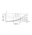
第2に、給電コイルが一つの平面スパイラルコイルからなる一般的な電力伝送装置(以下、シングルコイルの場合という。)と、本発明の第1実施形態にかかる非接触式電力伝送装置1(以下、ダブルコイルの場合という)とで受電コイル電圧の負荷抵抗RLに対する依存特性にどの程度の差が生じるかを確認するべく行ったシミュレーションの結果を比較する。シミュレーションは、結合係数kが0.5、0.25、0.1の3タイプについてそれぞれ行った。 Second, a general power transmission device (hereinafter referred to as a single coil) in which the feeding coil is a single planar spiral coil and a non-contact power transmission device 1 (hereinafter referred to as a single coil) according to the first embodiment of the present invention. And the case of a double coil) are compared with the results of simulations performed to confirm how much difference occurs in the dependence characteristics of the receiving coil voltage on the load resistance RL. The simulation was performed for each of the three types having a coupling coefficient k of 0.5, 0.25, and 0.1.
図25は、シングルコイルの場合についてシミュレーションした結果のグラフを示し、図26は、ダブルコイルの場合にかかるシミュレーションした結果のグラフを示している。図25及び図26において、横軸は受電装置側の回路の負荷抵抗を示し、縦軸は受電コイル電圧を示している。 FIG. 25 shows a graph of a result of simulation for the case of a single coil, and FIG. 26 shows a graph of a result of simulation for a case of a double coil. 25 and 26, the horizontal axis indicates the load resistance of the circuit on the power receiving device side, and the vertical axis indicates the power receiving coil voltage.
図25と図26の比較から明らかなように、受電コイル電圧は、ダブルコイルの場合の方が負荷抵抗が小さい場合には上昇し、負荷抵抗が大きな場合には下がっていることが分かる。既述のように、負荷抵抗に対する受電コイル電圧の変化が大きい場合、受電側において電源IC等を選定する際には、それだけ耐圧領域の広いものしか選定することができなかった。しかし、本実施形態の非接触式電力伝送装置1では、このシミュレーション結果から明らかなように、受電側において、耐圧領域の広いものを選定する必要のないことが分かる。即ち、選択することができるICの種類、幅が広がるのである。
As is clear from the comparison between FIG. 25 and FIG. 26, it can be seen that the power receiving coil voltage increases when the load resistance is small and decreases when the load resistance is large. As described above, when the change in the receiving coil voltage with respect to the load resistance is large, when the power supply IC or the like is selected on the power receiving side, only those having a wide withstand voltage region can be selected. However, in the contactless
第3に、給電コイルが1つの平面スパイラルコイルからなる一般的な非接触式電力伝送装置(以下、シングルコイルの場合という。)と、本発明の第1実施形態にかかる非接触式電力伝送装置1(ダブルコイルの場合)とにいて、受電特性の比較実験を行った。実験は、給電側の共振回路に周波数250kHzの5V振幅のパルス波を印加し、給電コイルと受電コイルの結合係数を0.25となるように設定し、受電側において、負荷抵抗RLが5Ω、10Ω、25Ω、50Ω、75Ω、100Ω、250Ω、500Ω、750Ω、及び1000Ωの時の、受電コイル端電圧Vout(ただし、信号の状態での電圧振幅)、負荷抵抗電流Iout(ただし、信号の状態での電流振幅)を測定した。そして、測定結果に基づいて負荷抵抗での消費電力Pw、受電コイル端電圧VoutのDC換算値Vdco、負荷抵抗電流IoutのDC換算値Idcを算出し、算出結果を比較した。 Third, a general non-contact power transmission device (hereinafter referred to as a single coil) in which the feeding coil is a single planar spiral coil, and a non-contact power transmission device according to the first embodiment of the present invention. 1 (in the case of a double coil), a comparative experiment of power reception characteristics was conducted. In the experiment, a 5 V amplitude pulse wave with a frequency of 250 kHz is applied to the resonance circuit on the power supply side, the coupling coefficient between the power supply coil and the power reception coil is set to 0.25, and the load resistance RL is 5Ω on the power reception side. 10Ω, 25Ω, 50Ω, 75Ω, 100Ω, 250Ω, 500Ω, 750Ω, and 1000Ω, receiving coil end voltage Vout (however, voltage amplitude in the signal state), load resistance current Iout (however, in the signal state) Current amplitude). Then, based on the measurement results, the power consumption Pw at the load resistance, the DC conversion value Vdco of the receiving coil end voltage Vout, and the DC conversion value Idc of the load resistance current Iout were calculated, and the calculation results were compared.
なお、測定結果に基づいて負荷抵抗での消費電力Pw、受電コイル端電圧VoutのDC換算値Vdco、負荷抵抗電流IoutのDC換算値Idcは、それぞれ次の換算式により求めている。 Based on the measurement results, the power consumption Pw at the load resistance, the DC converted value Vdco of the receiving coil end voltage Vout, and the DC converted value Idc of the load resistance current Iout are obtained by the following conversion formulas.
Pw=(Vout×Iout)/√2
Vdco=Vout/√2
Idc=Iout/√2
Pw = (Vout × Iout) / √2
Vdco = Vout / √2
Idc = Iout / √2
表4は、ダブルコイルの場合の実験結果を示し、表5は、シングルコイルの場合の実験結果をそれぞれ示している。 Table 4 shows the experimental results in the case of a double coil, and Table 5 shows the experimental results in the case of a single coil.
そして、表4及び表5に示した受電コイル端電圧Vout、負荷抵抗電流Iout、消費電力Pwについてダブルコイルの場合のものと、シングルコイルの場合のものとを抜き出してそれぞれ比較したものが、表6〜表8である。なお、表6の上段において示した、VoutDは、ダブルコイルの場合に関する受電コイル端電圧Voutを、VoutSは、シングルコイルに関する受電コイル端電圧Voutをそれぞれ示している。同様に表7、表8において、上段に示した「D」の記号は、ダブルコイルの場合を表し、「S」の記号は、シングルコイルの場合を表している。 Then, for the receiving coil end voltage Vout, the load resistance current Iout, and the power consumption Pw shown in Tables 4 and 5, the case of the double coil and the case of the single coil are extracted and compared, respectively. 6 to Table 8. In addition, VoutD shown in the upper part of Table 6 represents the receiving coil end voltage Vout for the case of the double coil, and VoutS represents the receiving coil end voltage Vout for the single coil. Similarly, in Tables 7 and 8, the symbol “D” shown in the upper part represents the case of a double coil, and the symbol “S” represents the case of a single coil.
また、表6〜表8のデータに基づいて、受電側の負荷抵抗に対する受電コイル端電圧Vout、負荷抵抗電流Iout、消費電力Pwの変化をグラフに表したものが図27〜図29である。 27 to 29 are graphs showing changes in the receiving coil end voltage Vout, the load resistance current Iout, and the power consumption Pw with respect to the load resistance on the power receiving side based on the data in Tables 6 to 8.
表6及び図27に示されているように、負荷抵抗に対する受電コイル端電圧Voutは、負荷抵抗が1Ω〜25Ωの範囲では、ダブルコイルの場合の方が、シングルコイルの場合よりも電圧が高くなっている。一方、負荷抵抗が25Ωを超え、1000Ωまでの範囲においては、シングルコイルの場合には、負荷抵抗が大きくなるにつれ、電圧が大幅に大高くなっているが、ダブルコイルの場合には、負荷抵抗が大きくなっても、電圧の上昇がそれほど大きくなく、シングルコイルの場合に対する電圧の差が次第に広がっていることがわかる。 As shown in Table 6 and FIG. 27, the receiving coil end voltage Vout with respect to the load resistance is higher in the case of the double coil than in the case of the single coil when the load resistance is in the range of 1Ω to 25Ω. It has become. On the other hand, in the range of load resistance exceeding 25Ω and up to 1000Ω, in the case of a single coil, the voltage increases significantly as the load resistance increases, but in the case of a double coil, the load resistance increases. It can be seen that the increase in voltage does not increase so much, and the voltage difference with respect to the single coil gradually widens.
これに対し、表7及び図28に示しされているように、負荷抵抗に対する負荷抵抗電流Ioutは、負荷抵抗が1Ω〜25Ωの範囲では、ダブルコイルの場合の方が、シングルコイルの場合よりも電流値が大きくなっている。一方、負荷抵抗が25Ωを超え、1000Ωまでの範囲においては、逆に、ダブルコイルの場合の方が、シングルコイルの場合よりも電流値が小さくなっている。 On the other hand, as shown in Table 7 and FIG. 28, the load resistance current Iout with respect to the load resistance is larger in the case of the double coil than in the case of the single coil when the load resistance is in the range of 1Ω to 25Ω. The current value is large. On the other hand, in the range where the load resistance exceeds 25Ω and reaches 1000Ω, the current value is smaller in the case of the double coil than in the case of the single coil.
そして、表8及び図29に示したように、負荷抵抗に対する消費電力Pwは、負荷抵抗が1Ω〜25Ωの範囲では、ダブルコイルの場合の方が、シングルコイルの場合よりも大きな値となっている。一方、負荷抵抗が25Ωを超え、1000Ωまでの範囲においては、ダブルコイルの場合の方が、シングルコイルの場合に比べ消費電力Pwは小さくなっていることが分かる。 As shown in Table 8 and FIG. 29, the power consumption Pw with respect to the load resistance is larger in the case of the double coil than in the case of the single coil when the load resistance is in the range of 1Ω to 25Ω. Yes. On the other hand, in the range where the load resistance exceeds 25Ω and up to 1000Ω, the power consumption Pw is smaller in the case of the double coil than in the case of the single coil.
この実験結果から明らかなように、給電側においてQ値を下げることで、受電側において、負荷抵抗が1Ω〜25Ωの範囲では、受電コイル端電圧Voutを引き上げることができる。このことから、受電コイルの起電力を向上させることができる。一方、負荷抵抗が25Ωを超える範囲においては、負荷抵抗電流Ioutを引き下げることができる。このことから、発熱を抑えることができ、その結果、受電コイルの起電力を向上させることができるのである。 As is clear from the experimental results, by reducing the Q value on the power supply side, the power receiving coil end voltage Vout can be increased on the power receiving side when the load resistance is in the range of 1Ω to 25Ω. From this, the electromotive force of a receiving coil can be improved. On the other hand, in the range where the load resistance exceeds 25Ω, the load resistance current Iout can be reduced. Thus, heat generation can be suppressed, and as a result, the electromotive force of the power receiving coil can be improved.
さらに、上記シミュレーション結果においても述べたように、負荷抵抗に対する受電コイル電圧の変動を抑えることで、受電側において、耐圧領域の広いものを選定する必要のないことが分かる。即ち、選択することができるICの種類、幅が広がるのである。 Furthermore, as described in the simulation result, it is understood that it is not necessary to select a power receiving side having a wide withstand voltage region by suppressing fluctuations in the receiving coil voltage with respect to the load resistance. That is, the types and widths of ICs that can be selected are expanded.
1 電力伝送装置
10 給電装置
11 AC/DC変換回路
12 DC/AC変換回路
13 共振回路
14 駆動回路
15 制御回路
20 給電コイル
21 第1給電コイル
22 第2給電コイル
30 受電装置
31 受電コイル
40 給電コイル
41 第1給電コイル
42 第2給電コイル
43 第3給電コイル
45 給電コイル
46 第1給電コイル
47 第2給電コイル
48 受電コイル
50 給電コイル
51,52 平面スパイラルコイル
60 受電コイル
70 給電コイル
71,72,73 平面スパイラルコイル
80 受電コイル
90 給電コイル
91,92,93,94 平面スパイラルコイル
DESCRIPTION OF
100 受電コイル
110 給電コイル
111,112,113 平面スパイラルコイル
120 受電コイル
121,122 平面スパイラルコイル
130 給電コイル
140 受電コイル
141,142 平面スパイラルコイル
150 給電コイル
151 第1給電コイル
152 第2給電コイル
153,154 平面スパイラルコイル
160 受電コイル
170 給電コイル
171 第1給電コイル
172 第2給電コイル
173,174,175 平面スパイラルコイル
180 給電コイル
181 第1給電コイル
182 第2給電コイル
183,184,185,186 平面スパイラルコイル
190 給電コイル
191 第1給電コイル
192 第2給電コイル
193,194,195 平面スパイラルコイル
DESCRIPTION OF
200 受電コイル
201,202平面スパイラルコイル
210 給電コイル
211 第1給電コイル
212 第2給電コイル
213,214,215,126 平面スパイラルコイル
220 給電コイル
221,222 平面スパイラルコイル
230 給電コイル
231,232 平面スパイラルコイル
200
Claims (44)
前記給電装置は、前記給電コイルを含めて構成される共振回路を有し、
前記給電コイルは、複数の平面コイルで構成され、これら複数の平面コイルは、その素線が同一軸を中心として巻かれて形成され、かつ互いの自己インダクタンスの値が略同値とされたことを特徴とする非接触式電力伝送装置。 A power feeding device including a power feeding coil made of a planar coil formed by winding a wire in a spiral shape; and a power receiving device equipped with a power receiving coil made of a planar coil formed by winding the wire in a spiral shape, the power feeding A non-contact power transmission device that transmits electric power from the power feeding device to the power receiving device using electromagnetic induction between a coil and the power receiving coil,
The power feeding device has a resonance circuit configured including the power feeding coil,
The feeding coil is composed of a plurality of planar coils, and the plurality of planar coils are formed by winding the strands around the same axis, and the self-inductance values of the coils are substantially the same. A contactless power transmission device.
前記複数の平面コイルは、それぞれの前記空間部に外縁寸法の小さな平面コイルが順次配置され、
前記複数の平面コイルは並列接続されていることを特徴とする請求項2に記載の非接触式電力伝送装置。 The plurality of planar coils constituting the power supply coil are formed such that a space portion is formed in the center, and the inner edge dimension and the outer edge dimension of each other are sequentially reduced.
In the plurality of planar coils, planar coils having small outer edge dimensions are sequentially arranged in the space portions.
The contactless power transmission device according to claim 2, wherein the plurality of planar coils are connected in parallel.
前記2つの平面コイルのそれぞれの巻数が前記受電コイルの巻数よりも少ないことを特徴とする請求項3に記載の非接触式電力伝送装置。 The planar coil constituting the feeding coil is composed of two planar coils formed by winding two strands arranged in parallel around the same axis, at least the planar coil arranged at the innermost part. And the two planar coils are connected in parallel,
The contactless power transmission device according to claim 3, wherein the number of turns of each of the two planar coils is smaller than the number of turns of the power receiving coil.
前記平面コイル群を構成する各平面コイルは、前記受電コイルの巻数よりも少なく巻かれ、
前記平面コイル群の中から選択された平面コイルに電流が流されることを特徴とする請求項3に記載の非接触式電力伝送装置。 The planar coil arranged at least at the innermost of the planar coils constituting the feeding coil is constituted by a planar coil group formed by winding a plurality of strands arranged in parallel around the same axis,
Each planar coil constituting the planar coil group is wound less than the number of turns of the power receiving coil,
The contactless power transmission device according to claim 3, wherein a current is passed through a planar coil selected from the planar coil group.
前記平面コイル群を構成する各平面コイルは、前記受電コイルの巻数よりも少なく巻かれ、
前記平面コイル群の中から、それぞれの間に少なくとも1本の素線を挟んで選択された複数の素線により構成される平面コイルを並列に接続して電流が流されることを特徴とする請求項4に記載の非接触式電力伝送装置。 Among the planar coils constituting the power supply coil, at least the planar coil arranged in the innermost part is composed of a planar coil group formed by winding at least four strands arranged in parallel around the same axis. ,
Each planar coil constituting the planar coil group is wound less than the number of turns of the power receiving coil,
The planar coil comprised of a plurality of strands selected from the planar coil group with at least one strand sandwiched therebetween is connected in parallel to pass a current. Item 5. The non-contact power transmission device according to Item 4.
受電側の前記平面コイル群の中から選択された平面コイルが電磁誘導に利用されることを特徴とする請求項6又は請求項7に記載の非接触式電力伝送装置。 The power receiving coil is constituted by a planar coil group formed by winding a plurality of strands arranged in parallel around the same axis,
The contactless power transmission device according to claim 6 or 7, wherein a planar coil selected from the planar coil group on the power receiving side is used for electromagnetic induction.
前記2つの平面コイルは並列接続されたことを特徴とする請求項2に記載の非接触式電力伝送装置。 The feeding coil is composed of two planar coils formed by winding two strands arranged in parallel around the same axis,
The non-contact power transmission apparatus according to claim 2, wherein the two planar coils are connected in parallel.
前記平面コイル群を構成する各平面コイルは、前記受電コイルの巻数よりも少なく巻かれて形成され、
前記平面コイル群の中から選択された平面コイルに電流が流されることを特徴とする請求項2に記載の非接触式電力伝送装置。 The feeding coil is composed of a planar coil group formed by winding a plurality of strands arranged in parallel around the same axis,
Each planar coil constituting the planar coil group is formed by winding less than the number of turns of the power receiving coil,
The non-contact power transmission device according to claim 2, wherein a current is passed through a planar coil selected from the planar coil group.
前記平面コイル群を構成する各平面コイルは、前記受電コイルの巻数よりも少なく巻かれ、
前記平面コイル群の中から、それぞれの間に少なくとも1本の素線を挟んで選択された複数の素線により構成される平面コイルを並列に接続して電流が流されることを特徴とする請求項2に記載の非接触式電力伝送装置。 The feeding coil is constituted by a planar coil group formed by winding at least four strands arranged in parallel around the same axis,
Each planar coil constituting the planar coil group is wound less than the number of turns of the power receiving coil,
The planar coil comprised of a plurality of strands selected from the planar coil group with at least one strand sandwiched therebetween is connected in parallel to pass a current. Item 3. The non-contact power transmission device according to Item 2.
受電側の前記平面コイル群の中から選択された平面コイルが電磁誘導に利用されることを特徴とする請求項10又は請求項11に記載の非接触式電力伝送装置。 The power receiving coil is constituted by a planar coil group formed by winding a plurality of strands arranged in parallel around the same axis,
The contactless power transmission device according to claim 10 or 11, wherein a planar coil selected from the planar coil group on the power receiving side is used for electromagnetic induction.
各平面コイルの最内周の素線同士が接続されたことを特徴とする請求項13に記載の非接触式電力伝送装置。 The two planar coils are formed by winding two strands arranged in parallel around the same axis,
The contactless power transmission device according to claim 13, wherein the innermost strands of each planar coil are connected to each other.
前記給電装置は、前記給電コイルを含めて構成される共振回路を有し、
前記給電コイルは、複数の平面コイルで構成され、これら複数の平面コイルは、その素線が同一軸を中心として巻かれて形成され、かつ互いの自己インダクタンスの値が略同値とされたことを特徴とする給電装置。 Used to transmit power using electromagnetic induction from a feeding coil consisting of a planar coil formed by winding a strand to a receiving coil consisting of a planar coil formed by winding a strand. A power supply device,
The power feeding device has a resonance circuit configured including the power feeding coil,
The feeding coil is composed of a plurality of planar coils, and the plurality of planar coils are formed by winding the strands around the same axis, and the self-inductance values of the coils are substantially the same. Characteristic power supply device.
前記複数の平面コイルは、それぞれの前記空間部に外縁寸法の小さな平面コイルが順次配置され、
前記複数の平面コイルは並列接続されていることを特徴とする請求項16に記載の給電装置。 The plurality of planar coils constituting the power supply coil are formed such that a space portion is formed in the center, and the inner edge dimension and the outer edge dimension of each other are sequentially reduced.
In the plurality of planar coils, planar coils having small outer edge dimensions are sequentially arranged in the space portions.
The power feeding device according to claim 16, wherein the plurality of planar coils are connected in parallel.
前記平面コイル群の中から選択された平面コイルに電流が流されることを特徴とする請求項17に記載の給電装置。 The planar coil arranged at least at the innermost of the planar coils constituting the feeding coil is constituted by a planar coil group formed by winding a plurality of strands arranged in parallel around the same axis,
The power feeding device according to claim 17, wherein a current is passed through a planar coil selected from the planar coil group.
前記平面コイル群の中から、それぞれの間に少なくとも1本の素線を挟んで選択された複数の素線により構成される平面コイルを並列に接続して電流が流されることを特徴とする請求項17に記載の給電装置。 Among the planar coils constituting the power supply coil, at least the planar coil arranged in the innermost part is composed of a planar coil group formed by winding at least four strands arranged in parallel around the same axis. ,
The planar coil comprised of a plurality of strands selected from the planar coil group with at least one strand sandwiched therebetween is connected in parallel to pass a current. Item 18. The power feeding device according to Item 17.
前記2つの平面コイルは並列接続されたことを特徴とする請求項16に記載の給電装置。 The feeding coil is composed of two planar coils formed by winding two strands arranged in parallel around the same axis,
The power feeding device according to claim 16, wherein the two planar coils are connected in parallel.
前記平面コイル群の中から択一的に選択された平面コイルに電流が流されることを特徴とする請求項16に記載の給電装置。 The feeding coil is composed of a planar coil group formed by winding a plurality of strands arranged in parallel around the same axis,
The power feeding device according to claim 16, wherein a current is caused to flow through a planar coil that is alternatively selected from the group of planar coils.
前記平面コイル群の中から、それぞれの間に少なくとも1本の素線を挟んで選択された複数の素線により構成される平面コイルを並列に接続して電流が流されることを特徴とする請求項16に記載の給電装置。 The feeding coil is constituted by a planar coil group formed by winding at least four strands arranged in parallel around the same axis,
The planar coil comprised of a plurality of strands selected from the planar coil group with at least one strand sandwiched therebetween is connected in parallel to pass a current. Item 17. The power feeding device according to Item 16.
各平面コイルの最内周の素線同士が接続されたことを特徴とする請求項24に記載の給電装置。 The two planar coils are formed by winding two strands arranged in parallel around the same axis,
The power feeding device according to claim 24, wherein the innermost strands of each planar coil are connected to each other.
前記受電コイルは、並列に並べられた複数の素線が同一軸を中心に巻かれて形成された平面コイル群により構成され、
受電側の前記平面コイル群の中から選択された平面コイルが電磁誘導に利用されることを特徴とする受電装置。 Used to transmit power using electromagnetic induction from a feeding coil consisting of a planar coil formed by winding a strand to a receiving coil consisting of a planar coil formed by winding a strand. A power receiving device,
The power receiving coil is constituted by a planar coil group formed by winding a plurality of strands arranged in parallel around the same axis,
A power receiving apparatus, wherein a planar coil selected from the group of planar coils on a power receiving side is used for electromagnetic induction.
前記給電コイルは、複数の平面コイルで構成され、これら複数の平面コイルは、その素線が同一軸を中心として巻かれて形成され、かつ互いの自己インダクタンスの値が略同値とされたことを特徴とする電磁誘導用コイル。 Non-contact transmission of electric power using electromagnetic induction between a feeding coil composed of a planar coil formed by winding a wire in a spiral shape and a power receiving coil composed of a planar coil formed by winding a wire in a spiral shape A coil for electromagnetic induction used in an electric power transmission device,
The feeding coil is composed of a plurality of planar coils, and the plurality of planar coils are formed by winding the strands around the same axis, and the self-inductance values of the coils are substantially the same. Characteristic coil for electromagnetic induction.
前記複数の平面コイルは、それぞれの前記空間部に外縁寸法の小さな平面コイルが順次配置され、
前記複数の平面コイルは並列接続されていることを特徴とする請求項28に記載の電磁誘導用コイル。 The plurality of planar coils constituting the power supply coil are formed such that a space portion is formed in the center, and the inner edge dimension and the outer edge dimension of each other are sequentially reduced.
In the plurality of planar coils, planar coils having small outer edge dimensions are sequentially arranged in the space portions.
29. The electromagnetic induction coil according to claim 28, wherein the plurality of planar coils are connected in parallel.
前記2つの平面コイルのそれぞれの巻数が前記受電コイルの巻数よりも少ないことを特徴とする請求項29に記載の電磁誘導用コイル。 Of the planar coils constituting the power supply coil, at least the planar coil arranged in the innermost part is composed of two planar coils formed by winding two strands arranged in parallel around the same axis. And the two planar coils are connected in parallel,
30. The electromagnetic induction coil according to claim 29, wherein the number of turns of each of the two planar coils is smaller than the number of turns of the power receiving coil.
前記平面コイル群を構成する各平面コイルは、前記受電コイルの巻数よりも少なく巻かれて形成され、
前記平面コイル群には、この平面コイル群を構成する各平面コイルの中から電流を流す平面コイルを選択可能とする接続端子が設けられていることを特徴とする請求項29に記載の電磁誘導用コイル。 The planar coil arranged at least at the innermost of the planar coils constituting the feeding coil is constituted by a planar coil group formed by winding a plurality of strands arranged in parallel around the same axis,
Each planar coil constituting the planar coil group is formed by winding less than the number of turns of the power receiving coil,
30. The electromagnetic induction according to claim 29, wherein the planar coil group is provided with a connection terminal capable of selecting a planar coil that allows current to flow from each planar coil constituting the planar coil group. Coil.
前記平面コイル群を構成する各平面コイルは、前記受電コイルの巻数よりも少なく巻かれて形成され、
前記平面コイル群には、この平面コイル群を構成する各平面コイルの中から電流を流す複数の平面コイルを、選択されない他の平面コイルの素線をそれぞれの間に挟んで選択可能な接続端子が設けられ、
選択された前記複数の平面コイルが並列に接続されていることを特徴とする請求項29に記載の電磁誘導用コイル。 Among the planar coils constituting the power supply coil, at least the planar coil arranged in the innermost part is composed of a planar coil group formed by winding at least four strands arranged in parallel around the same axis. ,
Each planar coil constituting the planar coil group is formed by winding less than the number of turns of the power receiving coil,
In the planar coil group, a plurality of planar coils that allow current to flow from among the planar coils that constitute the planar coil group, and a connection terminal that can be selected by sandwiching the wires of other planar coils that are not selected. Is provided,
30. The electromagnetic induction coil according to claim 29, wherein the plurality of selected planar coils are connected in parallel.
受電側の前記平面コイル群には、この平面コイル群の中から電磁誘導に利用される平面コイルを選択可能な接続端子が設けられたことを特徴とする請求項32又は請求項33に記載の電磁誘導用コイル。 The power receiving coil is constituted by a planar coil group formed by winding a plurality of strands arranged in parallel around the same axis,
The planar coil group on the power receiving side is provided with a connection terminal capable of selecting a planar coil to be used for electromagnetic induction from the planar coil group. Electromagnetic induction coil.
前記2つの平面コイルのそれぞれの巻数が前記受電コイルの巻数よりも少ないことを特徴とする請求項28に記載の電磁誘導用コイル。 The planar coil constituting the feeding coil is composed of two planar coils formed by winding two strands arranged in parallel around the same axis, and the two planar coils are connected in parallel. ,
The coil for electromagnetic induction according to claim 28, wherein the number of turns of each of the two planar coils is smaller than the number of turns of the power receiving coil.
前記平面コイル群を構成する各平面コイルは、前記受電コイルの巻数よりも少なく巻かれ、
前記平面コイル群には、この平面コイル群を構成する各平面コイルの中から電流を流す平面コイルを選択可能とする接続端子が設けられていることを特徴とする請求項28に記載の電磁誘導用コイル。 The feeding coil is composed of a planar coil group formed by winding a plurality of strands arranged in parallel around the same axis,
Each planar coil constituting the planar coil group is wound less than the number of turns of the power receiving coil,
29. The electromagnetic induction according to claim 28, wherein the planar coil group is provided with a connection terminal capable of selecting a planar coil that allows current to flow from each planar coil constituting the planar coil group. Coil.
前記平面コイル群を構成する各平面コイルは、前記受電コイルの巻数よりも少なく巻かれ、
前記平面コイル群には、この平面コイル群を構成する各平面コイルの中から電流を流す複数の平面コイルを、選択されない他の平面コイルの素線をそれぞれの間に挟んで選択可能な接続端子が設けられ、
選択された前記複数の平面コイルが並列に接続されていることを特徴とする請求項28に記載の電磁誘導用コイル。 The feeding coil is constituted by a planar coil group formed by winding at least four strands arranged in parallel around the same axis,
Each planar coil constituting the planar coil group is wound less than the number of turns of the power receiving coil,
In the planar coil group, a plurality of planar coils that allow current to flow from among the planar coils that constitute the planar coil group, and a connection terminal that can be selected by sandwiching the wires of other planar coils that are not selected. Is provided,
29. The electromagnetic induction coil according to claim 28, wherein the selected plurality of planar coils are connected in parallel.
前記平面コイル群には、この平面コイル群を構成する各平面コイルの中から電磁誘導に利用する平面コイルを選択可能とする接続端子が設けられていることを特徴とする請求項38又は請求項39に記載の電磁誘導用コイル。 The power receiving coil is constituted by a planar coil group formed by winding a plurality of strands arranged in parallel around the same axis,
The said planar coil group is provided with the connection terminal which enables selection of the planar coil utilized for electromagnetic induction from each planar coil which comprises this planar coil group. 39. The electromagnetic induction coil according to 39.
各平面コイルの最内周の素線同士が接続されたことを特徴とする請求項43に記載の電磁誘導用コイル。 The two planar coils are formed by winding two strands arranged in parallel around the same axis,
44. The electromagnetic induction coil according to claim 43, wherein innermost strands of each planar coil are connected to each other.
Priority Applications (1)
| Application Number | Priority Date | Filing Date | Title |
|---|---|---|---|
| JP2010255216A JP5710220B2 (en) | 2010-11-15 | 2010-11-15 | Non-contact power transmission device, and power feeding device, power receiving device and electromagnetic induction coil used therefor |
Applications Claiming Priority (1)
| Application Number | Priority Date | Filing Date | Title |
|---|---|---|---|
| JP2010255216A JP5710220B2 (en) | 2010-11-15 | 2010-11-15 | Non-contact power transmission device, and power feeding device, power receiving device and electromagnetic induction coil used therefor |
Publications (3)
| Publication Number | Publication Date |
|---|---|
| JP2012110080A true JP2012110080A (en) | 2012-06-07 |
| JP2012110080A5 JP2012110080A5 (en) | 2013-12-12 |
| JP5710220B2 JP5710220B2 (en) | 2015-04-30 |
Family
ID=46495078
Family Applications (1)
| Application Number | Title | Priority Date | Filing Date |
|---|---|---|---|
| JP2010255216A Expired - Fee Related JP5710220B2 (en) | 2010-11-15 | 2010-11-15 | Non-contact power transmission device, and power feeding device, power receiving device and electromagnetic induction coil used therefor |
Country Status (1)
| Country | Link |
|---|---|
| JP (1) | JP5710220B2 (en) |
Cited By (12)
| Publication number | Priority date | Publication date | Assignee | Title |
|---|---|---|---|---|
| WO2014109460A1 (en) * | 2013-01-09 | 2014-07-17 | 한국전기연구원 | Wireless power transmission system for free-position wireless charging of multiple devices |
| KR101497140B1 (en) * | 2013-01-09 | 2015-03-03 | 한국전기연구원 | Wireless Power Transfer System for Free Positioning Charging of Multiple Devices |
| WO2015040650A1 (en) * | 2013-09-17 | 2015-03-26 | パナソニックIpマネジメント株式会社 | Contactless power transmission device |
| KR20150090065A (en) * | 2012-10-19 | 2015-08-05 | 퀄컴 인코포레이티드 | System and method for inductance compensation in wireless power transfer |
| JP2015231329A (en) * | 2014-06-03 | 2015-12-21 | ヒタチ−エルジー データ ストレージ コリア,インコーポレイティド | Wireless power transmission device |
| JP2016093088A (en) * | 2014-11-01 | 2016-05-23 | パナソニックIpマネジメント株式会社 | Power transmission device, vehicle having the same and radio power transmission system |
| JP2016093087A (en) * | 2014-11-01 | 2016-05-23 | パナソニックIpマネジメント株式会社 | Power transmission device, vehicle having the same and radio power transmission system |
| JPWO2014024934A1 (en) * | 2012-08-07 | 2016-07-25 | レキオ・パワー・テクノロジー株式会社 | Lighting device, power supply device and lighting fixture |
| JP2017526323A (en) * | 2014-07-08 | 2017-09-07 | ワイトリシティ コーポレーションWitricity Corporation | Resonator balancing in wireless power transfer systems |
| CN107507697A (en) * | 2017-08-25 | 2017-12-22 | 深圳顺络电子股份有限公司 | A kind of coil, wireless charging structure and preparation method thereof, electronic equipment |
| JP2020516222A (en) * | 2017-04-07 | 2020-05-28 | オッポ広東移動通信有限公司Guangdong Oppo Mobile Telecommunications Corp., Ltd. | Wireless charging device, device to be charged and control method thereof |
| US10726989B2 (en) | 2015-12-01 | 2020-07-28 | Ihi Corporation | Coil device |
Citations (5)
| Publication number | Priority date | Publication date | Assignee | Title |
|---|---|---|---|---|
| JP2005312285A (en) * | 2004-03-23 | 2005-11-04 | Japan Science & Technology Agency | Device and method for non-contact power feeding and the device with built-in structure |
| JP2008136311A (en) * | 2006-11-29 | 2008-06-12 | Asuka Electron Kk | Composite planar coil |
| JP2009158598A (en) * | 2007-12-25 | 2009-07-16 | Panasonic Electric Works Co Ltd | Planar coil and non-contact power transfer device using the same |
| JP2010016235A (en) * | 2008-07-04 | 2010-01-21 | Panasonic Electric Works Co Ltd | Plane coil |
| JP2010040699A (en) * | 2008-08-04 | 2010-02-18 | Showa Aircraft Ind Co Ltd | Noncontacting feed device |
-
2010
- 2010-11-15 JP JP2010255216A patent/JP5710220B2/en not_active Expired - Fee Related
Patent Citations (5)
| Publication number | Priority date | Publication date | Assignee | Title |
|---|---|---|---|---|
| JP2005312285A (en) * | 2004-03-23 | 2005-11-04 | Japan Science & Technology Agency | Device and method for non-contact power feeding and the device with built-in structure |
| JP2008136311A (en) * | 2006-11-29 | 2008-06-12 | Asuka Electron Kk | Composite planar coil |
| JP2009158598A (en) * | 2007-12-25 | 2009-07-16 | Panasonic Electric Works Co Ltd | Planar coil and non-contact power transfer device using the same |
| JP2010016235A (en) * | 2008-07-04 | 2010-01-21 | Panasonic Electric Works Co Ltd | Plane coil |
| JP2010040699A (en) * | 2008-08-04 | 2010-02-18 | Showa Aircraft Ind Co Ltd | Noncontacting feed device |
Cited By (19)
| Publication number | Priority date | Publication date | Assignee | Title |
|---|---|---|---|---|
| JPWO2014024934A1 (en) * | 2012-08-07 | 2016-07-25 | レキオ・パワー・テクノロジー株式会社 | Lighting device, power supply device and lighting fixture |
| KR20150090065A (en) * | 2012-10-19 | 2015-08-05 | 퀄컴 인코포레이티드 | System and method for inductance compensation in wireless power transfer |
| JP2015537499A (en) * | 2012-10-19 | 2015-12-24 | クアルコム,インコーポレイテッド | System and method for inductance compensation in wireless power transfer |
| KR102150138B1 (en) | 2012-10-19 | 2020-08-31 | 위트리시티 코포레이션 | System and method for inductance compensation in wireless power transfer |
| US9711278B2 (en) | 2013-01-09 | 2017-07-18 | Korea Electrotechnology Research Institute | Wireless power transmission system for free-position wireless charging of multiple devices |
| KR101497140B1 (en) * | 2013-01-09 | 2015-03-03 | 한국전기연구원 | Wireless Power Transfer System for Free Positioning Charging of Multiple Devices |
| WO2014109460A1 (en) * | 2013-01-09 | 2014-07-17 | 한국전기연구원 | Wireless power transmission system for free-position wireless charging of multiple devices |
| US10141105B2 (en) | 2013-01-09 | 2018-11-27 | Korea Electrotechnology Research Institute | Wireless power transmission system for free-position wireless charging of multiple devices |
| WO2015040650A1 (en) * | 2013-09-17 | 2015-03-26 | パナソニックIpマネジメント株式会社 | Contactless power transmission device |
| CN105765677A (en) * | 2013-09-17 | 2016-07-13 | 松下知识产权经营株式会社 | Contactless power transmission device |
| EP3057113A4 (en) * | 2013-09-17 | 2016-08-17 | Panasonic Ip Man Co Ltd | Contactless power transmission device |
| JP2015231329A (en) * | 2014-06-03 | 2015-12-21 | ヒタチ−エルジー データ ストレージ コリア,インコーポレイティド | Wireless power transmission device |
| JP2017526323A (en) * | 2014-07-08 | 2017-09-07 | ワイトリシティ コーポレーションWitricity Corporation | Resonator balancing in wireless power transfer systems |
| JP2016093087A (en) * | 2014-11-01 | 2016-05-23 | パナソニックIpマネジメント株式会社 | Power transmission device, vehicle having the same and radio power transmission system |
| JP2016093088A (en) * | 2014-11-01 | 2016-05-23 | パナソニックIpマネジメント株式会社 | Power transmission device, vehicle having the same and radio power transmission system |
| US10726989B2 (en) | 2015-12-01 | 2020-07-28 | Ihi Corporation | Coil device |
| JP2020516222A (en) * | 2017-04-07 | 2020-05-28 | オッポ広東移動通信有限公司Guangdong Oppo Mobile Telecommunications Corp., Ltd. | Wireless charging device, device to be charged and control method thereof |
| US11437848B2 (en) | 2017-04-07 | 2022-09-06 | Guangdong Oppo Mobile Telecommunications Corp., Ltd. | Wireless charging device, device to-be-charged, and method for controlling charging |
| CN107507697A (en) * | 2017-08-25 | 2017-12-22 | 深圳顺络电子股份有限公司 | A kind of coil, wireless charging structure and preparation method thereof, electronic equipment |
Also Published As
| Publication number | Publication date |
|---|---|
| JP5710220B2 (en) | 2015-04-30 |
Similar Documents
| Publication | Publication Date | Title |
|---|---|---|
| JP5710220B2 (en) | Non-contact power transmission device, and power feeding device, power receiving device and electromagnetic induction coil used therefor | |
| KR101248499B1 (en) | Plane coil | |
| JP6450027B2 (en) | Wireless power transmitter and receiver for vehicles | |
| US9876396B2 (en) | Wireless power transmitting apparatus and wireless power transmission system | |
| EP2581921B1 (en) | Wireless power transmitter | |
| US10923966B2 (en) | Coil structures for alignment and inductive wireless power transfer | |
| US9742199B2 (en) | Contactless power supply system and contactless extension plug | |
| JP3226466U (en) | Coil module and wireless electric energy transmission circuit using the same | |
| US20130307469A1 (en) | Contactless power supply system and power transmission coil for contactless power supply system | |
| JP2009504115A (en) | Wireless charger with improved charging efficiency variation | |
| CN104952606B (en) | Wireless power transmission coil and Contactless power transmission device | |
| JP2012110080A5 (en) | ||
| JP2009106126A (en) | Power transmitter, power transmission device and power receiving device of power transmitter | |
| JP6551853B2 (en) | Power transmission device, vehicle equipped with power transmission device and wireless power transmission system | |
| US11387680B2 (en) | Coreless power transformer | |
| KR20210034781A (en) | Wireless power transfer apparatus and system including the same | |
| CN108462261B (en) | Coil module, electric energy transmitting circuit and electric energy receiving circuit | |
| EP3507884A1 (en) | Segmented and longitudinal receiver coil arrangements for wireless power transfer | |
| JP2014230474A (en) | Non-contact power supply system | |
| KR101216752B1 (en) | Flyback converter using coaxial cable transformer | |
| US20150188364A1 (en) | Wireless power receiving apparatus and wireless power transmitting apparatus | |
| TWM508836U (en) | A wireless charging coil PCB structure | |
| JP5612956B2 (en) | Non-contact power transmission device | |
| JP2011229202A (en) | Wireless power transmission coil | |
| JP6384633B2 (en) | Coil antenna, power feeding device, power receiving device, and wireless power feeding system |
Legal Events
| Date | Code | Title | Description |
|---|---|---|---|
| A521 | Written amendment |
Free format text: JAPANESE INTERMEDIATE CODE: A523 Effective date: 20131029 |
|
| A621 | Written request for application examination |
Free format text: JAPANESE INTERMEDIATE CODE: A621 Effective date: 20131029 |
|
| A977 | Report on retrieval |
Free format text: JAPANESE INTERMEDIATE CODE: A971007 Effective date: 20140704 |
|
| A131 | Notification of reasons for refusal |
Free format text: JAPANESE INTERMEDIATE CODE: A131 Effective date: 20140729 |
|
| A521 | Written amendment |
Free format text: JAPANESE INTERMEDIATE CODE: A523 Effective date: 20140929 |
|
| A131 | Notification of reasons for refusal |
Free format text: JAPANESE INTERMEDIATE CODE: A131 Effective date: 20141104 |
|
| A521 | Written amendment |
Free format text: JAPANESE INTERMEDIATE CODE: A523 Effective date: 20150105 |
|
| TRDD | Decision of grant or rejection written | ||
| A01 | Written decision to grant a patent or to grant a registration (utility model) |
Free format text: JAPANESE INTERMEDIATE CODE: A01 Effective date: 20150203 |
|
| A61 | First payment of annual fees (during grant procedure) |
Free format text: JAPANESE INTERMEDIATE CODE: A61 Effective date: 20150304 |
|
| R150 | Certificate of patent or registration of utility model |
Ref document number: 5710220 Country of ref document: JP Free format text: JAPANESE INTERMEDIATE CODE: R150 |
|
| R250 | Receipt of annual fees |
Free format text: JAPANESE INTERMEDIATE CODE: R250 |
|
| R250 | Receipt of annual fees |
Free format text: JAPANESE INTERMEDIATE CODE: R250 |
|
| R250 | Receipt of annual fees |
Free format text: JAPANESE INTERMEDIATE CODE: R250 |
|
| LAPS | Cancellation because of no payment of annual fees |