JP2012107675A - Rolling bearing and method for manufacturing rolling bearing - Google Patents
Rolling bearing and method for manufacturing rolling bearing Download PDFInfo
- Publication number
- JP2012107675A JP2012107675A JP2010255900A JP2010255900A JP2012107675A JP 2012107675 A JP2012107675 A JP 2012107675A JP 2010255900 A JP2010255900 A JP 2010255900A JP 2010255900 A JP2010255900 A JP 2010255900A JP 2012107675 A JP2012107675 A JP 2012107675A
- Authority
- JP
- Japan
- Prior art keywords
- bearing
- rolling
- rolling bearing
- pulley
- hydrogen embrittlement
- Prior art date
- Legal status (The legal status is an assumption and is not a legal conclusion. Google has not performed a legal analysis and makes no representation as to the accuracy of the status listed.)
- Pending
Links
Images


Abstract
Description
本発明は、転がり軸受に関し、特に、軌道部材および転動体のうち少なくとも1つの軸受部材がJIS規格SUJ2からなる転がり軸受および転がり軸受の製造方法に関するものである。 The present invention relates to a rolling bearing, and more particularly to a rolling bearing in which at least one bearing member of a raceway member and a rolling element is made of JIS standard SUJ2, and a method for manufacturing the rolling bearing.
水が混入する条件下、すべりを伴う条件下、通電が起きる条件下などで転がり軸受が使用されると、水または潤滑剤が分解して発生した水素が軌道部材および転動体の鋼中に侵入することにより早期はく離が起きることがある。水素は鋼の疲労強度を著しく低下させるため、軌道部材および転動体の接触要素間が油膜で分断される弾性流体潤滑と考えられる条件でも、接触要素の交番せん断応力が最大になる転がり表層内部に亀裂が発生することがある。この亀裂が伝播して早期はく離に至ることがある。今後、コンパクト化や省エネ化に対応するため、水が混入する条件下、すべりを伴う条件下、通電が起きる条件下など転がり軸受の使用条件はますます厳しくなる傾向にある。そのため、耐水素脆性に優れた転がり軸受が必要になると予想される。 When rolling bearings are used under conditions where water is mixed, slipping, or energized, hydrogen generated by decomposition of water or lubricant will enter the steel of the raceway member and rolling element. Doing so may cause early peeling. Since hydrogen significantly reduces the fatigue strength of steel, even in conditions that are considered to be elastohydrodynamic lubrication in which the contact element between the raceway member and rolling element is divided by an oil film, the alternating shear stress of the contact element is maximized inside the rolling surface layer. Cracks may occur. This crack may propagate and lead to early peeling. In the future, in order to cope with downsizing and energy saving, the usage conditions of rolling bearings tend to become more severe, such as conditions where water is mixed, conditions involving slippage, and conditions where energization occurs. Therefore, it is expected that a rolling bearing having excellent hydrogen embrittlement resistance will be required.
転がり軸受の耐水素脆性を向上させる従来技術として、たとえば特開2000−282178号公報(特許文献1)には、鉄鋼材料中のCr(クロム)含有率を所定の値にして不動態膜であるクロム酸化膜を所定の厚さで形成することにより、鉄鋼材料中への水素の侵入を抑制することが開示されている。 As a conventional technique for improving the hydrogen embrittlement resistance of a rolling bearing, for example, Japanese Patent Application Laid-Open No. 2000-282178 (Patent Document 1) discloses a passive film having a predetermined Cr (chromium) content in a steel material. It is disclosed that the entry of hydrogen into a steel material is suppressed by forming a chromium oxide film with a predetermined thickness.
また、鋼の強化のために窒化処理が有効であることが知られている。たとえば、論文「鋼中窒素濃度を正確に管理した浸炭窒化SUJ2鋼の人工痕付与による圧痕起点型はく離寿命評価」(非特許文献1)には、窒素濃度を正確に管理した鋼の圧痕起点型はく離寿命評価が開示されている。 It is also known that nitriding treatment is effective for strengthening steel. For example, in the paper “Evaluation of indentation-origin type peeling life by artificial marking of carbonitrided SUJ2 steel with precisely controlled nitrogen concentration in steel” (Non-Patent Document 1), the indentation-initiated type of steel with precisely controlled nitrogen concentration A peel life assessment is disclosed.
上記公報では、Cr含有率を所定の値にするためにCrを多く添加することで炭化物が粗大化し、それが応力集中源となって早期はく離が起きることがある。 また、不動態膜には、水素の拡散を遅くする効果があるが、発生した水素が鋼表面に吸着するのを促進する効果もある。したがって、間欠的に使われる転がり軸受の場合には、停止時に水素が散逸するため、不動態膜によって鋼中への水素の侵入を遅らせることは、早期はく離の抑制に有効と考えられる。しかしながら、連続して使われる転がり軸受の場合には、不動態膜が多くの水素を吸着するため、鋼中に侵入する水素量が増すので、早期はく離が発生する可能性が高くなる。今後、無人で連続稼動される転がり軸受が増えることが予想される。従来技術では、特にそのような用途に対して早期はく離の抑制が不十分である。 In the above-mentioned publication, carbide is coarsened by adding a large amount of Cr in order to set the Cr content to a predetermined value, which may become a stress concentration source and cause early separation. In addition, the passive film has an effect of slowing the diffusion of hydrogen, but also has an effect of promoting the adsorption of the generated hydrogen on the steel surface. Therefore, in the case of a rolling bearing that is used intermittently, hydrogen is dissipated at the time of stoppage. Therefore, it is considered effective to suppress early separation by delaying the penetration of hydrogen into the steel by the passive film. However, in the case of a rolling bearing that is used continuously, the passive film adsorbs a lot of hydrogen, so that the amount of hydrogen that penetrates into the steel increases, so that there is a high possibility that early separation will occur. In the future, it is expected that the number of rolling bearings that are continuously operated unattended will increase. In the prior art, suppression of early peeling is insufficient particularly for such applications.
また、Crの含有率を所定の値にした特殊鋼材は、コストが高くなるという問題がある。また、Crの含有率を所定の値にした特殊鋼材は、海外で調達することが困難であるという問題がある。 Moreover, the special steel material which made the content rate of Cr predetermined value has the problem that cost becomes high. Moreover, there is a problem that it is difficult to procure a special steel material having a predetermined Cr content.
また、上記論文では、耐水素脆性については検討されていないため、対水素脆性を向上させることはできない。 Further, in the above paper, hydrogen embrittlement resistance is not studied, so that hydrogen embrittlement cannot be improved.
また、軸受の発熱は、軸の熱膨張をもたらし、加工精度悪化の原因の1つとなる。たとえばマシニングセンタなどの工作機械において高速回転で使用される工作機械主軸用転がり軸受では、高速回転時の発熱を避けるため低トルク化することが重要である。このため、工作機械主軸用転がり軸受は、発熱の原因となる軸受の摩擦トルクを低減するため潤滑油量を極限まで少なくしている。そのため、十分な潤滑油が供給される場合と比較して、油膜厚さが減少するので、すべりによる潤滑油のせん断応力が大きくなることから、水素が発生しやすくなると推定される。また、工作機械主軸用転がり軸受には、特にアンギュラ玉軸受が多用されている。アンギュラ玉軸受では、転動体(玉)と軌道部材(軌道輪)との間には必ずすべりが生じている。さらに、実際の使用においては、軌道部材および転動体へのクーラントの浸入が避けられない。水溶性クーラントの場合、クーラントの進入は、水が混入することに他ならない。したがって、工作機械主軸用転がり軸受では、水素が鋼中に侵入することにより早期はく離が発生しやすい。 Further, the heat generation of the bearing causes thermal expansion of the shaft, which is one of the causes of deterioration of machining accuracy. For example, in a rolling bearing for a main spindle of a machine tool used at a high speed in a machine tool such as a machining center, it is important to reduce the torque in order to avoid heat generation during the high speed rotation. For this reason, the rolling bearings for machine tool main spindles reduce the amount of lubricating oil as much as possible in order to reduce the friction torque of the bearings that causes heat generation. For this reason, the oil film thickness is reduced as compared with the case where sufficient lubricating oil is supplied, and the shear stress of the lubricating oil due to slip increases, so that hydrogen is likely to be generated. In addition, angular ball bearings are frequently used as rolling bearings for machine tool spindles. In angular ball bearings, slip always occurs between the rolling elements (balls) and the race members (race rings). Further, in actual use, it is inevitable that coolant enters the raceway member and the rolling element. In the case of water-soluble coolant, the entry of the coolant is nothing but water mixing. Therefore, in a rolling bearing for a machine tool main shaft, early peeling is likely to occur due to hydrogen penetrating into steel.
本発明は、上記課題を鑑みてなされたものであり、その目的は、水素脆性起因の早期はく離を抑制できる転がり軸受を提供することである。 This invention is made | formed in view of the said subject, The objective is to provide the rolling bearing which can suppress the early peeling resulting from hydrogen embrittlement.
本発明者は、鋭意検討した結果、軌道部材および転動体のうち少なくとも1つの軸受部材の転走面の窒化処理および軸受部材の焼戻温度の最適化によって、塑性変形しにくくして原子空孔を生成しにくくすることにより、転がり軸受の耐水素脆性が向上することを見出した。本発明者は、軌道部材および転動体のうち少なくとも1つの軸受部材として、素材のコストと調達性を鑑み、転がり軸受に最もよく用いられる高炭素クロム軸受鋼SUJ2(JIS規格)を選択した。 As a result of intensive studies, the present inventor has made the atomic vacancies difficult to plastically deform by nitriding the rolling surface of at least one bearing member of the race member and the rolling element and optimizing the tempering temperature of the bearing member. It has been found that the hydrogen embrittlement resistance of a rolling bearing is improved by making it difficult to generate the. The present inventor has selected high-carbon chromium bearing steel SUJ2 (JIS standard) most frequently used for rolling bearings as the bearing member and at least one of the rolling elements in view of the cost and availability of the material.
本発明者は、軸受部材の転走面に窒化処理を施して焼入した後、耐水素脆性を向上するために焼戻温度を最適化した。軸受部材の転走面に窒化処理を施すことによって軸受部材が塑性変形しにくくなる。本発明者は、軸受部材の転走面に窒化処理を施すことによって軸受部材が塑性変形しにくくなることで軸受部材の耐水素脆性が向上することを見出した。 The inventor optimized the tempering temperature in order to improve hydrogen embrittlement resistance after nitriding the rolling contact surface of the bearing member and quenching. By subjecting the rolling surface of the bearing member to nitriding treatment, the bearing member is hardly plastically deformed. The present inventor has found that the hydrogen embrittlement resistance of the bearing member is improved by performing nitriding treatment on the rolling surface of the bearing member to make the bearing member difficult to be plastically deformed.
焼戻温度の最適化の根拠は、水素脆化機構として有力な水素助長ひずみ誘起空孔理論に基づいている。塑性変形により原子空孔が増加するが、水素が関与すると原子空孔密度の増大を助長することを系統だった実験によって見出したことがこの理論の根拠となっている。本発明者は、この理論に着目し、焼戻温度の最適化によって耐水素脆性が向上することを見出した。 The basis for optimizing the tempering temperature is based on the theory of hydrogen-assisted strain-induced vacancies, which is a powerful hydrogen embrittlement mechanism. The number of vacancies increases due to plastic deformation, but this theory is based on the fact that it has been found by systematic experiments that when hydrogen is involved, it increases the vacancy density. The inventor paid attention to this theory and found that hydrogen embrittlement resistance was improved by optimizing the tempering temperature.
本発明の転がり軸受は、円環状の軌道を有する軌道部材と、軌道部材に接触し、円環状の軌道上に転動自在に配置された複数の転動体とを備えている。軌道部材および転動体のうち少なくとも1つの軸受部材は、JIS規格SUJ2からなっている。軸受部材は焼入れされている。軸受部材は窒化処理された転走面を有している。軸受部材に直径19.05mmのSUJ2製標準転がり軸受用鋼球を荷重3.18kNで押し付け、10秒間保持した後に除荷することにより軸受部材に形成される圧痕の深さが0.2μm以下である。転走面のロックウェルCスケール硬さがHRC61.2以上HRC63.3以下である。 The rolling bearing of the present invention includes a raceway member having an annular raceway and a plurality of rolling elements that are in contact with the raceway member and are arranged so as to be freely rollable on the annular raceway. At least one bearing member of the race member and the rolling element is made of JIS standard SUJ2. The bearing member is quenched. The bearing member has a nitriding rolling surface. By pressing a steel ball for SUJ2 standard rolling bearings with a diameter of 19.05 mm on the bearing member with a load of 3.18 kN, holding it for 10 seconds and then unloading it, the depth of the impression formed on the bearing member is 0.2 μm or less. is there. The Rockwell C scale hardness of the rolling surface is HRC61.2 or more and HRC63.3 or less.
軸受部材の転走面に窒化処理を施すことによって軸受部材が塑性変形しにくくなる。軸受部材の転走面に窒化処理を施すことによって軸受部材が塑性変形しにくくなることで、軸受部材の耐水素脆性が向上する。 By subjecting the rolling surface of the bearing member to nitriding treatment, the bearing member is hardly plastically deformed. By subjecting the rolling surface of the bearing member to nitriding treatment, the bearing member is less likely to be plastically deformed, thereby improving the hydrogen embrittlement resistance of the bearing member.
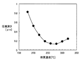
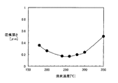
また、塑性変形により原子空孔密度は増大する。圧痕深さによって塑性変形しにくさが示される。つまり圧痕深さが小さければ塑性変形しにくいといえる。圧痕深さは、目安として0.2μm以下であれば塑性変形しにくいといえる。そこで、焼戻温度と圧痕深さとの関係を詳細に調査したところ、240℃以上300℃以下で焼戻処理を施せば、軸受部材に直径19.05mmのSUJ2製標準転がり軸受用鋼球を荷重3.18kNで押し付け、10秒間保持した後に除荷することにより軸受部材に形成される圧痕の深さが0.2μm以下となることがわかった。 Moreover, the atomic vacancy density increases due to plastic deformation. The indentation depth indicates the difficulty of plastic deformation. In other words, if the indentation depth is small, it can be said that plastic deformation is difficult. If the indentation depth is 0.2 μm or less as a guide, it can be said that plastic deformation is difficult. Therefore, when the relationship between the tempering temperature and the indentation depth was investigated in detail, if a tempering treatment was performed at 240 ° C. or higher and 300 ° C. or lower, SUJ2 standard rolling bearing steel balls with a diameter of 19.05 mm were loaded on the bearing member It was found that the depth of the indentation formed on the bearing member was 0.2 μm or less by unloading after pressing at 3.18 kN and holding for 10 seconds.
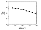
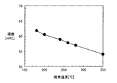
また、焼戻温度240℃以上300℃以下の範囲における軸受部材の転走面のロックウェルCスケール硬さは、HRC61.2以上HRC63.3以下となることがわかった。
Further, it was found that the Rockwell C scale hardness of the rolling surface of the bearing member in the range of
したがって、窒化処理された転走面を有する軸受部材に焼戻温度240℃以上300℃以下で焼戻しを施すことにより、塑性変形しにくくして原子空孔を生成しにくくすることができる。これにより、耐水素脆性を向上することができるので水素脆性起因の早期はく離を抑制できる。 Therefore, by tempering the bearing member having a rolling surface subjected to nitriding treatment at a tempering temperature of 240 ° C. or higher and 300 ° C. or lower, it is difficult to plastically deform and to make it difficult to generate atomic vacancies. Thereby, since hydrogen embrittlement resistance can be improved, early peeling due to hydrogen embrittlement can be suppressed.
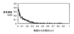
上記の転がり軸受において好ましくは、転走面の表面窒化濃度が0.05質量%以上0.4質量%以下である。 In the above rolling bearing, the surface nitriding concentration of the rolling surface is preferably 0.05% by mass or more and 0.4% by mass or less.
転走面の表面窒化濃度は0.05質量%未満では窒化による寿命向上の効果が十分に得られない。転走面の表面窒化濃度が0.4質量%より大きいとCr炭窒化物が多く生成されるため焼入性に寄与するCr量が欠乏する。そのため、十分な焼入性が確保できない。よって、転走面の表面窒化濃度が0.05質量%以上0.4質量%以下とすることで、窒化による寿命向上の効果を十分に得ることができ、十分な焼入性を確保することもできる。 If the surface nitridation concentration of the rolling surface is less than 0.05% by mass, the effect of improving the life by nitriding cannot be obtained sufficiently. If the surface nitridation concentration on the rolling surface is larger than 0.4% by mass, a large amount of Cr carbonitride is produced, so that the Cr amount contributing to hardenability is deficient. Therefore, sufficient hardenability cannot be ensured. Therefore, when the surface nitridation concentration of the rolling surface is 0.05 mass% or more and 0.4 mass% or less, the effect of improving the life by nitriding can be sufficiently obtained, and sufficient hardenability is ensured. You can also.
本発明者は転動体として、生産性を鑑み、窒化処理されていないJIS規格SUJ2を選択した。圧痕深さは、目安として0.2μm以下であれば塑性変形しにくいといえる。そこで、焼戻温度と圧痕深さとの関係を詳細に調査したところ、240℃以上280℃以下で焼戻処理を施せば、転動体に直径19.05mmのSUJ2製標準転がり軸受用鋼球を荷重1.97kNで押し付け、10秒間保持した後に除荷することにより転動体に形成される圧痕の深さが0.2μm以下となることがわかった。したがって、焼戻温度を240℃以上280℃以下で焼戻しを施すことにより、塑性変形しにくくして原子空孔を生成しにくくすることができる。これにより、耐水素脆性を向上することができるので水素脆性起因の早期はく離を抑制できる。 The present inventor has selected JIS standard SUJ2 which is not nitrided in consideration of productivity as a rolling element. If the indentation depth is 0.2 μm or less as a guide, it can be said that plastic deformation is difficult. Therefore, when the relationship between the tempering temperature and the indentation depth was investigated in detail, if a tempering treatment was performed at 240 ° C. or higher and 280 ° C. or lower, a SUJ2 standard rolling bearing steel ball having a diameter of 19.05 mm was loaded on the rolling element. It was found that by pressing at 1.97 kN and holding for 10 seconds before unloading, the depth of the indentation formed on the rolling element was 0.2 μm or less. Therefore, by performing tempering at a tempering temperature of 240 ° C. or higher and 280 ° C. or lower, it is difficult to plastically deform and make it difficult to generate atomic vacancies. Thereby, since hydrogen embrittlement resistance can be improved, early peeling due to hydrogen embrittlement can be suppressed.
上記の転がり軸受において好ましくは、転動体全体のロックウェルCスケール硬さがHRC57.0以上HRC58.9以下である。焼戻温度240以上280以下の範囲における転動体全体のロックウェルCスケール硬さは、HRC57.0以上HRC58.9以下である。
In the rolling bearing described above, the Rockwell C scale hardness of the entire rolling element is preferably HRC57.0 or more and HRC58.9 or less. The Rockwell C scale hardness of the whole rolling element in the range of tempering
上記の転がり軸受において好ましくは、転動体がセラミックスを含む材質よりなっている。本発明の転がり軸受によれば、転動体が水素脆性を示さないセラミックスを含む材質よりなっているため、耐水素脆性を向上することができるので水素脆性起因の早期はく離を抑制できる。 In the above rolling bearing, the rolling element is preferably made of a material containing ceramics. According to the rolling bearing of the present invention, since the rolling element is made of a material containing ceramics that does not exhibit hydrogen embrittlement, the hydrogen embrittlement resistance can be improved, so that early separation due to hydrogen embrittlement can be suppressed.
上記の転がり軸受において好ましくは、転動体を保持するための保持器をさらに備え、保持器が金属を含む材質よりなっている。本発明の転がり軸受によれば、通電が起きる条件下では、金属保持器の方が樹脂保持器よりも水素脆性起因の早期はく離が起きにくいので、水素脆性起因の早期はく離を抑制できる。 Preferably, the rolling bearing further includes a cage for holding the rolling elements, and the cage is made of a material containing metal. According to the rolling bearing of the present invention, under the condition where energization occurs, the metal cage is less likely to cause early peeling due to hydrogen embrittlement than the resin cage, and therefore, early peeling due to hydrogen embrittlement can be suppressed.
本発明の転がり軸受の製造方法によれば、円環状の軌道を有する軌道部材と、軌道部材に接触し、円環状の軌道上に転動自在に配置された複数の転動体とを備え、以下の工程を有している。軌道部材および転動体のうち少なくとも1つの軸受部材を、JIS規格SUJ2の材質からなるように準備する。軸受部材の転走面に窒化処理を施して焼入れする。焼入れられた軸受部材を240℃以上300℃以下で焼戻しする。 According to the method of manufacturing a rolling bearing of the present invention, the rolling bearing includes a raceway member having an annular raceway, and a plurality of rolling elements that are in contact with the raceway member and are arranged to be freely rollable on the annular raceway. It has the process of. At least one bearing member of the race member and the rolling element is prepared to be made of a material of JIS standard SUJ2. The rolling surface of the bearing member is subjected to nitriding treatment and quenched. The quenched bearing member is tempered at 240 ° C. or higher and 300 ° C. or lower.
軸受部材の転走面に窒化処理を施して焼入れすることにより軸受部材が塑性変形しにくくする。軸受部材の転走面に窒化処理を施して軸受部材が塑性変形しにくくなることで、軸受部材の耐水素脆性が向上する。 The bearing member is hard to be plastically deformed by performing nitriding treatment and quenching on the rolling surface of the bearing member. By subjecting the rolling surface of the bearing member to nitriding treatment and making the bearing member difficult to plastically deform, the hydrogen embrittlement resistance of the bearing member is improved.
焼入れられた軸受部材を240℃以上300℃以下で焼戻しすることにより、軸受部材を塑性変形しにくくして原子空孔を生成しにくくすることができる。これにより、耐水素脆性を向上することができるので水素脆性起因の早期はく離を抑制できる。 By tempering the quenched bearing member at 240 ° C. or higher and 300 ° C. or lower, the bearing member is less likely to be plastically deformed, and it is possible to make it difficult to generate atomic vacancies. Thereby, since hydrogen embrittlement resistance can be improved, early peeling due to hydrogen embrittlement can be suppressed.
上記の転がり軸受の製造方法において好ましくは、窒化処理は850℃の温度でRXガスにアンモニアガスを添加した雰囲気中で行われる。これにより、軸受部材の転走面に十分な窒化処理を施して軸受部材が塑性変形しにくくなることで、軸受部材の耐水素脆性を向上することができる。 In the above rolling bearing manufacturing method, the nitriding treatment is preferably performed at a temperature of 850 ° C. in an atmosphere in which ammonia gas is added to RX gas. Thereby, sufficient nitriding treatment is performed on the rolling surface of the bearing member to make the bearing member difficult to be plastically deformed, so that the hydrogen embrittlement resistance of the bearing member can be improved.
上記の転がり軸受において好ましくは、モータの主軸と、主軸の外周面に対向するように配置されるハウジングとをさらに備え、主軸をハウジングに対して回転可能に支持する。 Preferably, the rolling bearing further includes a main shaft of the motor and a housing disposed so as to face the outer peripheral surface of the main shaft, and the main shaft is rotatably supported with respect to the housing.
本発明の転がり軸受によれば、水素脆性起因の早期はく離を抑制できるので、軸受に水が混入する条件下、すべりを伴う条件下、通電が起きる条件下などの厳しい使用条件下においても長寿命なモータ用転がり軸受を提供することができる。 According to the rolling bearing of the present invention, since early peeling due to hydrogen embrittlement can be suppressed, a long service life can be obtained even under severe use conditions such as conditions where water is mixed in the bearing, conditions involving slippage, and conditions where energization occurs. It is possible to provide a rolling bearing for a simple motor.
上記の転がり軸受において好ましくは、工作機械の主軸と、主軸の外周面に対向するように配置されるハウジングとをさらに備え、主軸をハウジングに対して回転可能に支持する。 Preferably, the rolling bearing further includes a main shaft of the machine tool and a housing disposed so as to face the outer peripheral surface of the main shaft, and the main shaft is rotatably supported with respect to the housing.
本発明の転がり軸受によれば、水素脆性起因の早期はく離を抑制できるので、軸受に水が混入する条件下、すべりを伴う条件下、通電が起きる条件下などの厳しい使用条件下においても長寿命な工作機械主軸用転がり軸受を提供することができる。また、高速回転時の発熱の原因となる軸受の摩擦トルクを低減するため潤滑油の油膜厚さを減少させた使用条件下においても長寿命な工作機械主軸用転がり軸受を提供することができる。 According to the rolling bearing of the present invention, since early peeling due to hydrogen embrittlement can be suppressed, a long service life can be obtained even under severe use conditions such as conditions where water is mixed in the bearing, conditions involving slippage, and conditions where energization occurs. A rolling bearing for a main spindle of a machine tool can be provided. Further, it is possible to provide a rolling bearing for a machine tool spindle that has a long life even under use conditions in which the oil film thickness of the lubricating oil is reduced in order to reduce the friction torque of the bearing that causes heat generation during high-speed rotation.
上記の転がり軸受において好ましくは、車輪の回転側部材と、回転側部材の外周面に対向するように配置される固定側部材とをさらに備え、回転側部材を固定側部材に対して回転可能に支持する。 Preferably, the rolling bearing further includes a rotation-side member of the wheel and a fixed-side member disposed so as to face the outer peripheral surface of the rotation-side member, and the rotation-side member is rotatable with respect to the fixed-side member. To support.
本発明の転がり軸受によれば、水素脆性起因の早期はく離を抑制できるので、軸受に水が混入する条件下、すべりを伴う条件下、通電が起きる条件下などの厳しい使用条件下においても長寿命な車輪用転がり軸受を提供することができる。また、軸受が振動する条件下においても水素脆性起因の早期はく離を抑制できるので、長寿命な車輪用転がり軸受を提供することができる。 According to the rolling bearing of the present invention, since early peeling due to hydrogen embrittlement can be suppressed, a long service life can be obtained even under severe use conditions such as conditions where water is mixed in the bearing, conditions involving slippage, and conditions where energization occurs. A rolling bearing for a wheel can be provided. Further, since the early peeling due to hydrogen embrittlement can be suppressed even under conditions where the bearing vibrates, a long-life wheel rolling bearing can be provided.
上記の転がり軸受において好ましくは、オルタネータの主軸と、主軸の外周面に対向するように配置されるハウジングとをさらに備え、主軸をハウジングに対して回転可能に支持する。 Preferably, the rolling bearing further includes a main shaft of the alternator and a housing disposed so as to face the outer peripheral surface of the main shaft, and the main shaft is rotatably supported with respect to the housing.
本発明の転がり軸受によれば、水素脆性起因の早期はく離を抑制できるので、軸受に水が混入する条件下、すべりを伴う条件下、通電が起きる条件下などの厳しい使用条件下においても長寿命なオルタネータ用転がり軸受を提供することができる。特に急加減速条件下で接触要素間にすべりが生じる影響により水素脆性起因の早期はく離が起きやすい使用条件下において、水素脆性起因の早期はく離を抑制することにより長寿命なオルタネータ用転がり軸受を提供することができる。また、サーペンタイン化に伴う負荷荷重の増加および荷重変動の増大によって従来よりもすべりが誘発される条件下においても水素脆性起因の早期はく離を抑制できるので、長寿命なオルタネータ用転がり軸受を提供することができる。 According to the rolling bearing of the present invention, since early peeling due to hydrogen embrittlement can be suppressed, a long service life can be obtained even under severe use conditions such as conditions where water is mixed in the bearing, conditions involving slippage, and conditions where energization occurs. A rolling bearing for an alternator can be provided. Providing rolling bearings for alternators that have a long life by suppressing early delamination due to hydrogen embrittlement, especially under operating conditions where sliding due to hydrogen embrittlement is likely to occur due to the effect of slippage between contact elements under rapid acceleration / deceleration conditions can do. In addition, it is possible to suppress the early peeling due to hydrogen embrittlement even under conditions where slippage is induced more than before due to increased load load and increased load fluctuation associated with serpentine formation, so a rolling bearing for an alternator with a long life is provided. Can do.
上記の転がり軸受において好ましくは、主軸と、主軸の外周面に対向するように配置されるプーリ本体とをさらに備え、主軸をプーリ本体に対して回転可能に支持する。 Preferably, the rolling bearing further includes a main shaft and a pulley main body disposed so as to face the outer peripheral surface of the main shaft, and the main shaft is rotatably supported with respect to the pulley main body.
本発明の転がり軸受によれば、水素脆性起因の早期はく離を抑制できるので、軸受に水が混入する条件下、すべりを伴う条件下、通電が起きる条件下などの厳しい使用条件下においても長寿命なプーリ用転がり軸受を提供することができる。また、サーペンタイン化に伴う負荷荷重の増加および荷重変動の増大によって従来よりもすべりが誘発される条件下においても水素脆性起因の早期はく離を抑制できるので、長寿命なプーリ用転がり軸受を提供することができる。 According to the rolling bearing of the present invention, since early peeling due to hydrogen embrittlement can be suppressed, a long service life can be obtained even under severe use conditions such as conditions where water is mixed in the bearing, conditions involving slippage, and conditions where energization occurs. A pulley rolling bearing can be provided. Also, since it is possible to suppress early peeling due to hydrogen embrittlement even under conditions in which slippage is induced more than before due to increased load load and increased load fluctuation associated with serpentine conversion, a long-life pulley rolling bearing is provided. Can do.
上記の転がり軸受において好ましくは、カーエアコン電磁クラッチプーリと、カーエアコン電磁クラッチプーリの内周面に対向するように配置されるプーリ用軸受支持部材とをさらに備え、カーエアコン電磁クラッチプーリをプーリ用軸受支持部材に対して回転可能に支持する。 Preferably, the rolling bearing further includes a car air conditioner electromagnetic clutch pulley and a pulley bearing support member disposed so as to face the inner peripheral surface of the car air conditioner electromagnetic clutch pulley, and the car air conditioner electromagnetic clutch pulley is used for the pulley. The bearing support member is rotatably supported.
本発明の転がり軸受によれば、水素脆性起因の早期はく離を抑制できるので、軸受に水が混入する条件下、すべりを伴う条件下、通電が起きる条件下などの厳しい使用条件下においても長寿命なカーエアコン電磁クラッチプーリ用転がり軸受を提供することができる。また、サーペンタイン化に伴う負荷荷重の増加および荷重変動の増大によって従来よりもすべりが誘発される条件下においても水素脆性起因の早期はく離を抑制できるので、長寿命なカーエアコン電磁クラッチプーリ用転がり軸受を提供することができる。 According to the rolling bearing of the present invention, since early peeling due to hydrogen embrittlement can be suppressed, a long service life can be obtained even under severe use conditions such as conditions where water is mixed in the bearing, conditions involving slippage, and conditions where energization occurs. A rolling bearing for a car air conditioner electromagnetic clutch pulley can be provided. In addition, rolling bearings for car air conditioner electromagnetic clutch pulleys that have a long service life can be prevented because early peeling due to hydrogen embrittlement can be suppressed even under conditions in which slippage is induced more than before due to increased load load and increased load fluctuation associated with serpentine conversion. Can be provided.
上記の転がり軸受において好ましくは、無段変速機のプーリ軸と、プーリ軸の外周面に対向するように配置されるハウジングとをさらに備え、プーリ軸をハウジングに対して回転可能に支持する。 Preferably, the rolling bearing further includes a pulley shaft of the continuously variable transmission and a housing disposed so as to face the outer peripheral surface of the pulley shaft, and the pulley shaft is rotatably supported with respect to the housing.
本発明の転がり軸受によれば、水素脆性起因の早期はく離を抑制できるので、軸受に水が混入する条件下、すべりを伴う条件下、通電が起きる条件下などの厳しい使用条件下においても長寿命な無段変速機用転がり軸受を提供することができる。また、軸受のアキシャルすきまを抑えるために軸受内外輪の溝曲率が小さく設定されたことにより軸受運転時の差動すべりが大きくなる条件下においても水素脆性起因の早期はく離を抑制できるので長寿命な無段変速機用転がり軸受を提供することができる。 According to the rolling bearing of the present invention, since early peeling due to hydrogen embrittlement can be suppressed, a long service life can be obtained even under severe use conditions such as conditions where water is mixed in the bearing, conditions involving slippage, and conditions where energization occurs. It is possible to provide a rolling bearing for a continuously variable transmission. In addition, since the groove curvature of the inner and outer rings of the bearing is set to be small in order to suppress the axial clearance of the bearing, it is possible to suppress early peeling due to hydrogen embrittlement even under conditions where differential sliding during bearing operation is large. A rolling bearing for a continuously variable transmission can be provided.
上記の転がり軸受において好ましくは、転がり軸受は、シェル形針状ころ軸受である。シェル形針状ころ軸受は、急加減速などのすべりを伴う条件下、特に、電磁クラッチの切り替えにより急加減速する自動車のエアーコンプレッサの支持に用いられる場合、始動時の加速が早いABS(Antilock Brake System)ポンプの支持に用いられる場合、汎用エンジンのコンロッドの大端に用いられる場合などに、転動体にすべりが生じやすく、水素脆性起因の早期はく離が起きることがある。 In the above rolling bearing, preferably, the rolling bearing is a shell needle roller bearing. Shell-shaped needle roller bearings have a fast acceleration at the time of start-up (antilock) when they are used to support air compressors in automobiles that are rapidly accelerated or decelerated by switching electromagnetic clutches, especially under conditions involving sliding such as sudden acceleration / deceleration. When used to support a Brake System pump, when it is used at the large end of a connecting rod of a general-purpose engine, the rolling element is likely to slip, and early separation due to hydrogen embrittlement may occur.
本発明の転がり軸受によれば、このような条件下においても水素脆性起因の早期はく離を抑制できるので長寿命なシェル形針状ころ軸受を提供することができる。 According to the rolling bearing of the present invention, since it is possible to suppress early separation due to hydrogen embrittlement even under such conditions, a long-life shell needle roller bearing can be provided.
上記の転がり軸受において好ましくは、転がり軸受は、ソリッド形針状ころ軸受である。ソリッド形針状ころ軸受は、急加減速などのすべりを伴う条件下、特に、電磁クラッチの切り替えにより急加減速する自動車のエアーコンプレッサの支持に用いられる場合、始動時の加速が早いトランスミッションの支持に用いられる場合、汎用エンジンのコンロッドの大端に用いられる場合などに、接触要素間にすべりが生じやすく、水素脆性起因の早期はく離が起きることがある。 In the above rolling bearing, preferably, the rolling bearing is a solid needle roller bearing. Solid needle roller bearings support transmissions that accelerate quickly during start-up, especially when used to support air compressors in automobiles that accelerate and decelerate suddenly by switching electromagnetic clutches under conditions involving sudden acceleration and deceleration. In the case of being used for a large-sized connecting rod of a general-purpose engine, slippage between contact elements is likely to occur, and early peeling due to hydrogen embrittlement may occur.
本発明の転がり軸受によれば、このような条件下においても水素脆性起因の早期はく離を抑制できるので長寿命なソリッド形針状ころ軸受を提供することができる。 According to the rolling bearing of the present invention, since it is possible to suppress early separation due to hydrogen embrittlement even under such conditions, a solid needle roller bearing having a long life can be provided.
上記の転がり軸受において好ましくは、転がり軸受は、スラスト針状ころ軸受である。スラスト針状ころ軸受は、転動体内外の周速差により、運転中は絶えず転動輪との間にすべりが生じており、水素脆性起因の早期はく離が起きることがある。スラスト針状ころ軸受は、急加減速などのすべりを伴う条件下でも水素脆性起因の早期はく離が起きることがある。本発明の転がり軸受によれば、このような条件下においても水素脆性起因の早期はく離を抑制できるので長寿命なスラスト針状ころ軸受を提供することができる。 In the above rolling bearing, preferably, the rolling bearing is a thrust needle roller bearing. The thrust needle roller bearing is constantly slipped from the rolling wheel during operation due to the difference in peripheral speed between the inside and outside of the rolling element, and may cause early separation due to hydrogen embrittlement. Thrust needle roller bearings may experience early peeling due to hydrogen embrittlement even under conditions involving slippage such as rapid acceleration and deceleration. According to the rolling bearing of the present invention, since it is possible to suppress early separation due to hydrogen embrittlement even under such conditions, a long-life thrust needle roller bearing can be provided.
上記の転がり軸受において好ましくは、転がり軸受は、保持器を含んでいる。保持器付き針状ころ軸受は、急加減速などのすべりを伴う条件下、特に、始動時の加速が速い自動車のトランスミッションのアイドラー軸受として用いられる場合、CVT(Continuously Variable Transmission)の遊星ピニオン支持軸受として用いられる場合、二輪エンジンや汎用エンジンのコンロッドの大端用軸受として用いられる場合などに、転動体にすべりが生じやすく、水素脆性起因の早期はく離が起きることがある。本発明の転がり軸受によれば、このような条件下においても水素脆性起因の早期はく離を抑制できるので長寿命な保持器付き針状ころ軸受を提供することができる。 In the above rolling bearing, the rolling bearing preferably includes a cage. A needle roller bearing with a cage is a planetary pinion support bearing of CVT (Continuously Variable Transmission), particularly when used as an idler bearing for a vehicle transmission that accelerates quickly during acceleration, such as sudden acceleration / deceleration. When used as a bearing for a large end of a connecting rod of a two-wheeled engine or a general-purpose engine, the rolling element easily slips and may cause early peeling due to hydrogen embrittlement. According to the rolling bearing of the present invention, since it is possible to suppress early separation due to hydrogen embrittlement even under such conditions, a long-life needle roller bearing with a cage can be provided.
以上説明したように、本発明の転がり軸受および転がり軸受の製造方法によれば、水素脆性起因の早期はく離を抑制できる。 As described above, according to the rolling bearing and the manufacturing method of the rolling bearing of the present invention, early separation due to hydrogen embrittlement can be suppressed.
以下、本発明の一実施の形態について図に基づいて説明する。
まず、本発明の一実施の形態における転がり軸受を備えたモータの構成について説明する。
Hereinafter, an embodiment of the present invention will be described with reference to the drawings.
First, the structure of the motor provided with the rolling bearing in one embodiment of the present invention will be described.
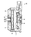
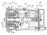
図1を参照して、本発明の一実施の形態におけるモータ90は、円盤状の形状を有し、コイルを備えたロータ91と、ロータ91を取り囲むように配置されたフレーム(ハウジング)93と、ロータ91の中心(回転軸)を含む部位に接続されるとともにフレーム93を貫通し、ロータ91と一体に軸まわりに回転可能に構成された主軸92とを備えている。そして、主軸92の外周面92Aと、フレーム93において主軸92の外周面92Aに対向する部分との間には、モータ用転がり軸受としてのグリース封入深溝玉軸受1が嵌め込まれている。すなわち、グリース封入深溝玉軸受1は、モータ90の主軸92を、主軸92の外周面92Aに対向するように配置されるフレーム93に対して回転自在に支持するモータ用転がり軸受である。
Referring to FIG. 1, a
さらに、モータ90は、フレーム93の内部において、ロータ91の外周面に対向するようにフレーム93に対して固定して配置された磁石を含むステータ96と、ロータ91において、ロータ91から見て主軸92がフレーム93の外部に突出する側とは反対側の部位に接続され、ロータ91と一体に回転可能に構成された整流子94と、整流子94に接触するようにフレーム93に対して固定して配置されたブラシ95とを備えている。
Furthermore, the
次に、上記グリース封入深溝玉軸受1について説明する。
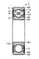
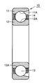
図2および図3を参照して、グリース封入深溝玉軸受1は、第1軌道部材としての外輪11と、第2軌道部材としての内輪12と、複数の転動体としての玉13と、保持器14と、シール部材15とを備えている。外輪11の内周面には、円環状の第1転走面としての外輪転走面11Aが形成されている。内輪12の外周面には、外輪転走面11Aに対向する円環状の第2転走面としての内輪転走面12Aが形成されている。また、複数の玉13には、転動体転走面としての玉転走面13A(玉13の表面)が形成されている。そして、当該玉13は、外輪転走面11Aおよび内輪転走面12Aの各々に玉転走面13Aにおいて接触し、円環状の保持器14により周方向に所定のピッチで配置されることにより、円環状の軌道上に転動自在に保持されている。
Next, the grease filled deep
2 and 3, a grease-filled deep
1対のシール部材15は、外輪11および内輪12に挟まれる空間、より具体的には外輪転走面11Aおよび内輪転走面12Aに挟まれる空間である軌道空間を閉じるように、外輪11と内輪12との間において、外輪11および内輪12の幅方向の両端部のそれぞれに配置されている。以上の構成により、グリース封入深溝玉軸受1の外輪11および内輪12は、互いに相対的に回転可能となっている。また、上記軌道空間には、グリース組成物16が封入されている。
The pair of
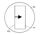
軌道部材としての外輪11、内輪12および転動体としての玉13のうち少なくとも1つの軸受部材は、JIS規格SUJ2からなっている。軌道部材としての外輪11、内輪12および転動体としての玉13のうち少なくとも1つの軸受部材は、焼入れされている。軌道部材としての外輪11、内輪12および転動体としての玉13のうち少なくとも1つの軸受部材は、窒化処理された転走面11A,12A,13Aを有している。窒化処理された領域NRは、外輪11、内輪12および転動体としての玉13の表面から内側に向かって形成されている。なお、以降の図では窒化処理された領域NRは図示されていないが、同様に外輪11、内輪12および転動体としての玉13の表面から内側に向かって形成されている。
At least one bearing member among the
軌道部材としての外輪11、内輪12および転動体としての玉13のうち少なくとも1つの軸受部材に直径19.05mmのSUJ2製標準転がり軸受用鋼球を荷重3.18kNで押し付け、10秒間保持した後に除荷することにより軸受部材に形成される圧痕の深さが0.2μm以下となっている。その軸受部材の転走面のロックウェルCスケール硬さがHRC61.2以上HRC63.3以下となっている。
After pressing a steel ball for SUJ2 standard rolling bearing with a diameter of 19.05 mm with a load of 3.18 kN to at least one bearing member among the
また、軌道部材としての外輪11、内輪12および転動体としての玉13のうち少なくとも1つの軸受部材の転走面11A、12A、13Aの表面窒化濃度が0.05質量%以上0.4質量%以下となっている。
Further, the surface nitriding concentration of the rolling surfaces 11A, 12A, and 13A of at least one bearing member among the
また、転動体としての玉13は、窒化処理されていないJIS規格SUJ2が選択されてもよい。この場合、玉13に直径19.05mmのSUJ2製標準転がり軸受用鋼球を荷重1.97kNで押し付け、10秒間保持した後に除荷することにより軸受部材に形成される圧痕の深さが0.2μm以下となっている。
Moreover, the ball |
また、転動体全体のロックウェルCスケール硬さがHRC57.0以上HRC58.9以下となっている。 Moreover, the Rockwell C scale hardness of the whole rolling element is HRC57.0 or more and HRC58.9 or less.
また、転動体としての玉13は、セラミックスを含む材質よりなることが好ましい。セラミックスとしては、窒化珪素やサイアロンなどが適用され得る。
Moreover, it is preferable that the ball |
セラミックスがサイアロンの1つであるβサイアロンを主成分とする焼結体である場合には、低圧(たとえば1MPa以下)の圧力下で焼結されるため、10MPa以上の圧力下で加圧焼結する窒化けい素を主成分とする焼結体よりも低コストで製造できる。 When the ceramic is a sintered body mainly composed of β sialon, which is one of sialon, it is sintered under a pressure of low pressure (for example, 1 MPa or less), so pressure sintering is performed under a pressure of 10 MPa or more. It can be manufactured at a lower cost than a sintered body mainly composed of silicon nitride.
βサイアロンを主成分とする焼結体は、βサイアロンが主成分であり、残部が不純物からなる焼結体である。βサイアロンは、Si6-ZALZN8-Zの組成式で表され、Zが0.1≦Z≦3.5の範囲を満たすように構成されている。不純物は、原料に由来するもの、または製造工程において混入するものを含み、不可避的不純物も含む。焼結助剤としては、マグネシウム(Mg)、アルミニウム(Al)、珪素(Si)、チタン(Ti)、希土類元素の酸化物、窒化物、酸窒化物のうち少なくとも1種類以上を採用することができる。焼結助剤は、焼結体のうち20質量%以下とすることが望ましい。 A sintered body containing β sialon as a main component is a sintered body in which β sialon is a main component and the balance is made of impurities. β sialon is represented by a composition formula of Si 6-Z AL Z N 8-Z and is configured so that Z satisfies a range of 0.1 ≦ Z ≦ 3.5. Impurities include those derived from raw materials or mixed in the manufacturing process, and also include inevitable impurities. As the sintering aid, at least one of magnesium (Mg), aluminum (Al), silicon (Si), titanium (Ti), rare earth element oxide, nitride, and oxynitride may be employed. it can. The sintering aid is preferably 20% by mass or less in the sintered body.
また、転動体としての玉13を保持するための保持器14は、金属を含む材質よりなることが好ましい。
Moreover, it is preferable that the holder |
次に、モータ90の動作について説明する。図1を参照して、図示しない電源から配線を介してブラシ95に供給された電流は、整流子94を介してロータ91のコイルを流れる。このとき、ロータ91のコイルを流れる電流と、磁石を含むステータ96により形成される磁界とにより生じる電磁力により、ロータ91は主軸92の軸まわりに、フレーム93に対して回転する。さらに、ロータ91が所定の角度回転すると、整流子94およびブラシ95のはたらきにより、ロータ91のコイルを流れる電流の向きが逆になり、さらにロータ91が回転する。これが繰り返されることにより、ロータ91はハウジングに対して連続的に回転し、当該回転は主軸92により外部に取り出される。
Next, the operation of the
次に、本発明の一実施の形態におけるモータ用転がり軸受の製造方法について説明する。 Next, the manufacturing method of the rolling bearing for motors in one embodiment of this invention is demonstrated.
図4を参照して、まず工程(S100)において、JIS規格SUJ2から構成される鋼材を準備する鋼材準備工程が実施される。具体的には、たとえばJIS規格SUJ2から構成される棒鋼や鋼線などが準備される。 Referring to FIG. 4, first, in a step (S100), a steel material preparation step for preparing a steel material composed of JIS standard SUJ2 is performed. Specifically, for example, steel bars or steel wires composed of JIS standard SUJ2 are prepared.
次に工程(S200)において、上記鋼材を成形することにより、モータ用転がり軸受の軸受部材の概略形状に成形された鋼製部材を作製する成形工程が実施される。具体的には、たとえば上記棒鋼や鋼線などに対して鍛造、旋削などの加工が実施されることにより、図2および図3に示される外輪11、内輪12、玉13などの概略形状に成形された鋼製部材が作製される。上記工程(S100)および(S200)は、モータ用転がり軸受の軸受部材の概略形状に成形された鋼製部材が準備される鋼製部材準備工程を構成する。
Next, in a process (S200), the shaping | molding process which produces the steel member shape | molded by the schematic shape of the bearing member of the rolling bearing for motors by shape | molding the said steel material is implemented. Specifically, for example, forging, turning, and the like are performed on the above-described steel bars and steel wires, and the
次に、工程(S300)において、鋼製部材に対して、A1点以上の温度からMS点以下の温度に冷却されることにより、当該鋼製部材が焼入硬化される焼入硬化工程が実施される。その後、工程(S400)において、焼入硬化された鋼製部材が、240℃以上300℃以下の温度域に加熱されて焼戻される焼戻工程が実施される。上記工程(S300)および(S400)は、鋼製部材が熱処理される熱処理工程を構成する。この熱処理工程の詳細については後述する。 Next, in the step (S300), the steel member is cooled from a temperature of A1 point or higher to a temperature of MS point or lower, whereby a quench hardening step is performed in which the steel member is hardened and hardened. Is done. Thereafter, in the step (S400), a tempering step is performed in which the quench-hardened steel member is heated to a temperature range of 240 ° C. or higher and 300 ° C. or lower and tempered. The steps (S300) and (S400) constitute a heat treatment step in which the steel member is heat treated. Details of this heat treatment step will be described later.
次に工程(S500)において、仕上げ工程が実施される。具体的には、熱処理工程が実施された鋼製部材に対して研削加工などの仕上げ加工が実施されることにより、外輪11、内輪12、玉13などが仕上げられる。これにより、本発明の一実施の形態におけるモータ用転がり軸受の軸受部材の製造方法が完了し、モータ用転がり軸受の軸受部材としての外輪11、内輪12、玉13などが完成する。
Next, in step (S500), a finishing step is performed. Specifically, the
さらに、工程(S600)において、組立て工程が実施される。具体的には、工程(S100)〜(S500)において作製された外輪11、内輪12、玉13と、別途準備された保持器14などとが組合わされて、本発明の一実施の形態におけるモータ用転がり軸受としてのグリース封入深溝玉軸受1が組立てられる。これにより、本発明の一実施の形態におけるモータ用転がり軸受の製造方法が完了し、モータ用転がり軸受としてのグリース封入深溝玉軸受1が完成する。
Further, in the process (S600), an assembly process is performed. Specifically, the
次に、熱処理工程の詳細について説明する。図5において、横方向は時間を示しており右に行くほど時間が経過していることを示している。また、図5において、縦方向は温度を示しており上に行くほど温度が高いことを示している。 Next, details of the heat treatment step will be described. In FIG. 5, the horizontal direction indicates time, and the time elapses toward the right. In FIG. 5, the vertical direction indicates the temperature, and the higher the temperature, the higher the temperature.
図5を参照して、工程(S200)において作製された鋼製部材は、まず、A1点以上の温度である温度T1に加熱され、時間t1だけ保持される。このとき、鋼製部材は、たとえばRXガスにアンモニアガスを添加した雰囲気中において加熱される。これにより、軸受部材の転走面となる鋼製部材の表面に窒化処理が施される。その後、鋼製部材が、たとえば油中に浸漬されることにより(油冷)、A1点以上の温度からMS点以下の温度に冷却されて、焼入が完了する。以上の手順により、焼入硬化工程が完了する。 Referring to FIG. 5, the steel member produced in the step (S200) is first heated to a temperature T1 that is a temperature equal to or higher than the A1 point, and is held for a time t1. At this time, the steel member is heated in an atmosphere in which ammonia gas is added to RX gas, for example. Thereby, the nitriding treatment is performed on the surface of the steel member which becomes the rolling surface of the bearing member. Thereafter, the steel member is immersed in oil (oil cooling), for example, to be cooled from a temperature not lower than the A1 point to a temperature not higher than the MS point, and quenching is completed. The quench hardening process is completed by the above procedure.
さらに、焼入硬化された鋼製部材がA1点以下の温度である温度T2に加熱され、t2だけ保持された後、たとえば室温まで空冷(放冷)されることにより焼戻工程が実施される。以上の工程により、本発明の一実施の形態における熱処理工程が完了する。 Furthermore, after the quench-hardened steel member is heated to a temperature T2 that is a temperature of A1 or lower and held for t2, the tempering step is performed by, for example, air cooling (cooling) to room temperature. . Through the above steps, the heat treatment step in one embodiment of the present invention is completed.
ここで、温度T1は、たとえば850℃の温度である。一方、時間t1は、たとえば180分間である。 Here, the temperature T1 is, for example, a temperature of 850 ° C. On the other hand, the time t1 is, for example, 180 minutes.
また、温度T2は、たとえば240℃以上300℃以下の温度である。一方、時間t2は、たとえば120分間である。 Moreover, temperature T2 is a temperature of 240 degreeC or more and 300 degrees C or less, for example. On the other hand, the time t2 is 120 minutes, for example.
ここで、A1点とは、鋼を加熱するときに、鋼の組織がフェライトからオーステナイトへ変態を開始する温度に相当する点を示す。また、MS点とは、オーステナイト化した鋼を冷却するときに、鋼の組織がマルテンサイトへ変態を開始する温度に相当する点を示す。 Here, the A1 point indicates a point corresponding to a temperature at which the steel structure starts transformation from ferrite to austenite when the steel is heated. Moreover, MS point shows the point corresponded to the temperature which the structure | tissue of steel starts a transformation to a martensite when austenitized steel is cooled.
上記本発明の一実施の形態におけるモータ用転がり軸受の軸受部材の製造方法では、鋼製部材準備工程において、素材のコストと調達性を鑑みてJIS規格SUJ2からなる鋼製部材が準備される。そして、焼入硬化工程において、窒化処理として850℃の温度でRXガスにアンモニアガスを添加した雰囲気中で焼入が施された上で、焼戻工程において鋼製部材が240℃以上300℃以下に加熱されて焼戻が実施される。その結果、上記本発明の一実施の形態におけるモータ用転がり軸受の軸受部材の製造方法によれば、モータ用転がり軸受の軸受部材を構成する鋼において、塑性変形しにくくして原子空孔を生成しにくくすることができる。 In the method for manufacturing a bearing member of a rolling bearing for a motor according to an embodiment of the present invention, a steel member made of JIS standard SUJ2 is prepared in the steel member preparation step in view of the cost and procurement of the material. In the quench hardening process, after quenching in an atmosphere in which ammonia gas is added to RX gas at a temperature of 850 ° C. as a nitriding process, the steel member is 240 ° C. or more and 300 ° C. or less in the tempering process. And tempering is performed. As a result, according to the manufacturing method of the bearing member of the rolling bearing for motor according to the above-described embodiment of the present invention, the steel constituting the bearing member of the rolling bearing for motor is less likely to be plastically deformed and generates atomic vacancies. Can be difficult.
転動体は生産性を鑑みて、窒化処理されていないJIS規格SUJ2からなっていてもよい。続いて、窒化処理されていないJIS規格SUJ2からなる転動体を有するモータ用転がり軸受の製造方法について説明する。 In consideration of productivity, the rolling element may be made of JIS standard SUJ2 which is not nitrided. Then, the manufacturing method of the rolling bearing for motors which has a rolling element which consists of JIS standard SUJ2 which is not nitrided is demonstrated.
図4を参照して、まず工程(S100)において、JIS規格SUJ2から構成される鋼材を準備する鋼材準備工程が実施される。具体的には、たとえばJIS規格SUJ2から構成される棒鋼や鋼線などが準備される。 Referring to FIG. 4, first, in a step (S100), a steel material preparation step for preparing a steel material composed of JIS standard SUJ2 is performed. Specifically, for example, steel bars or steel wires composed of JIS standard SUJ2 are prepared.
次に工程(S200)において、上記鋼材を成形することにより、モータ用転がり軸受の転動体の概略形状に成形された鋼製部材を作製する成形工程が実施される。具体的には、たとえば上記棒鋼や鋼線などに対して鍛造、旋削などの加工が実施されることにより、図2および図3に示される玉13の概略形状に成形された鋼製部材が作製される。上記工程(S100)および(S200)は、モータ用転がり軸受の軸受部材の概略形状に成形された鋼製部材が準備される鋼製部材準備工程を構成する。
Next, in a process (S200), the shaping | molding process which produces the steel member shape | molded by the rough shape of the rolling element of the rolling bearing for motors by shape | molding the said steel material is implemented. Specifically, for example, a steel member formed into the general shape of the
次に、工程(S300)において、鋼製部材に対して、A1点以上の温度からMS点以下の温度に冷却されることにより、当該鋼製部材が焼入硬化される焼入硬化工程が実施される。その後、工程(S400)において、焼入硬化された鋼製部材が、240℃以上280℃以下の温度域に加熱されて焼戻される焼戻工程が実施される。上記工程(S300)および(S400)は、鋼製部材が熱処理される熱処理工程を構成する。この熱処理工程の詳細については後述する。 Next, in the step (S300), the steel member is cooled from a temperature of A1 point or higher to a temperature of MS point or lower, whereby a quench hardening step is performed in which the steel member is hardened and hardened. Is done. Thereafter, in the step (S400), a tempering step is performed in which the quench-hardened steel member is heated to a temperature range of 240 ° C. or higher and 280 ° C. or lower and tempered. The steps (S300) and (S400) constitute a heat treatment step in which the steel member is heat treated. Details of this heat treatment step will be described later.
次に工程(S500)において、仕上げ工程が実施される。具体的には、熱処理工程が実施された鋼製部材に対して研削加工などの仕上げ加工が実施されることにより、玉13が仕上げられる。これにより、本発明の一実施の形態におけるモータ用転がり軸受の玉13が完成する。
Next, in step (S500), a finishing step is performed. Specifically, the
さらに、工程(S600)において、組立て工程が実施される。具体的には、工程(S100)〜(S500)において作製された玉13と、別途準備された外輪11、内輪12、保持器14などとが組合わされて、本発明の一実施の形態におけるモータ用転がり軸受としてのグリース封入深溝玉軸受1が組立てられる。これにより、本発明の一実施の形態における窒化処理されていないJIS規格SUJ2からなる転動体を有するモータ用転がり軸受の製造方法が完了し、モータ用転がり軸受としてのグリース封入深溝玉軸受1が完成する。
Further, in the process (S600), an assembly process is performed. Specifically, the
次に、熱処理工程の詳細について説明する。図5において、横方向は時間を示しており右に行くほど時間が経過していることを示している。また、図5において、縦方向は温度を示しており上に行くほど温度が高いことを示している。 Next, details of the heat treatment step will be described. In FIG. 5, the horizontal direction indicates time, and the time elapses toward the right. In FIG. 5, the vertical direction indicates the temperature, and the higher the temperature, the higher the temperature.
図5を参照して、工程(S200)において作製された鋼製部材は、まず、A1点以上の温度である温度T1に加熱され、時間t1だけ保持される。このとき、鋼製部材は、たとえばRXガス雰囲気中において加熱される。その後、鋼製部材が、たとえば油中に浸漬されることにより(油冷)、A1点以上の温度からMS点以下の温度に冷却されて、ずぶ焼入が完了する。以上の手順により、焼入硬化工程が完了する。 Referring to FIG. 5, the steel member produced in the step (S200) is first heated to a temperature T1 that is a temperature equal to or higher than the A1 point, and is held for a time t1. At this time, the steel member is heated, for example, in an RX gas atmosphere. Thereafter, the steel member is immersed, for example, in oil (oil cooling), so that the steel member is cooled from the temperature of the A1 point or higher to the temperature of the MS point or lower to complete the quenching. The quench hardening process is completed by the above procedure.
さらに、焼入硬化された鋼製部材がA1点以下の温度である温度T2に加熱され、t2だけ保持された後、たとえば室温まで空冷(放冷)されることにより焼戻工程が実施される。以上の工程により、本発明の一実施の形態における熱処理工程が完了する。 Furthermore, after the quench-hardened steel member is heated to a temperature T2 that is a temperature of A1 or lower and held for t2, the tempering step is performed by, for example, air cooling (cooling) to room temperature. . Through the above steps, the heat treatment step in one embodiment of the present invention is completed.
ここで、温度T1は、たとえば850℃の温度である。一方、時間t1は、たとえば80分間である。 Here, the temperature T1 is, for example, a temperature of 850 ° C. On the other hand, the time t1 is, for example, 80 minutes.
また、温度T2は、たとえば240℃以上280℃以下の温度である。一方、時間t2は、たとえば120分間である。 The temperature T2 is, for example, a temperature of 240 ° C. or higher and 280 ° C. or lower. On the other hand, the time t2 is 120 minutes, for example.
なお、上記では、本発明の一実施の形態の転がり軸受の一例としてグリース深溝玉軸受について説明した。また、本発明の一実施の形態の転がり軸受が適用される装置の一例として、モータについて説明した。本発明の一実施の形態の転がり軸受は、上記に限定されず、アンギュラ玉軸受、円筒ころ軸受などであってもよい。また、本発明の一実施の形態の転がり軸受は、工作機械主軸用転がり軸受に適用されてもよい。以下、本発明の一実施の形態の転がり軸受の別の例としてアンギュラ玉軸受および円筒ころ軸受について説明し、これらを備えた工作機械の構成について説明する。 In the above description, the grease deep groove ball bearing has been described as an example of the rolling bearing according to the embodiment of the present invention. Moreover, the motor was demonstrated as an example of the apparatus with which the rolling bearing of one embodiment of this invention is applied. The rolling bearing according to an embodiment of the present invention is not limited to the above, and may be an angular ball bearing, a cylindrical roller bearing, or the like. Moreover, the rolling bearing of one embodiment of the present invention may be applied to a rolling bearing for a machine tool main shaft. Hereinafter, an angular ball bearing and a cylindrical roller bearing will be described as another example of the rolling bearing according to the embodiment of the present invention, and the configuration of a machine tool including these will be described.
図6を参照して、本発明の一実施の形態における工作機械100は、円筒状の形状を有する主軸101と、主軸101の外周面を取り囲むハウジング102と、外輪の外周面がハウジングの内壁102Aに接触するとともに、内輪の内周面が主軸101の外周面101Aに接触するように、主軸101とハウジング102との間に嵌め込まれて配置された工作機械主軸用転がり軸受としてのアンギュラ玉軸受10(フロント軸受)および円筒ころ軸受20(リア軸受)を備えている。これにより、主軸101は、ハウジング102に対して軸まわりに回転自在に支持されている。
Referring to FIG. 6,
また、主軸101には、外周面101Aの一部を取り囲むようにモータロータ103Bが設置されており、ハウジング102の内壁102Aには、モータロータ103Bに対向する位置にモータステータ103Aが設置されている。このモータステータ103Aおよびモータロータ103Bは、モータ103(ビルトインモータ)を構成している。これにより、主軸101は、モータ103の動力によって、ハウジング102に対して相対的に回転可能となっている。
A
すなわち、アンギュラ玉軸受10および円筒ころ軸受20は、主軸101が回転することにより被加工物を加工する工作機械100において、回転駆動される主軸101を、主軸101に隣接して配置される部材であるハウジング102に対して回転自在に支持する工作機械主軸用転がり軸受である。
That is, the
次に、上記アンギュラ玉軸受10について説明する。
図7を参照して、アンギュラ玉軸受10は、工作機械主軸用転がり軸受の軸受部材である第1軌道部材としての外輪11と、第2軌道部材としての内輪12と、複数の転動体としての玉13と、保持器14とを備えている。外輪11には、円環状の第1転走面としての外輪転走面11Aが形成されている。内輪12には、外輪転走面11Aに対向する円環状の第2転走面としての内輪転走面12Aが形成されている。また、複数の玉13には、転動体転走面としての玉転走面13A(玉13の表面)が形成されている。そして、当該玉13は、外輪転走面11Aおよび内輪転走面12Aの各々に玉転走面13Aにおいて接触し、円環状の保持器14により周方向に所定のピッチで配置されることにより円環状の軌道上に転動自在に保持されている。これにより、外輪11と内輪12とは互いに相対的に回転可能となっている。
Next, the
Referring to FIG. 7, an
ここで、アンギュラ玉軸受10においては、玉13と外輪11との接触点と、玉13と内輪12との接触点とを結ぶ直線は、ラジアル方向(アンギュラ玉軸受10の回転軸に垂直な方向)に対して角度をなしている。そのため、ラジアル方向の荷重が負荷されると、アキシャル方向(アンギュラ玉軸受10の回転軸の方向)への分力が生じる。図6を参照して、本発明の一実施の形態の工作機械100では、前方側(主軸101の先端101B側)に同じ向きのアンギュラ玉軸受10を2つ配置するとともに、後方側(モータロータ103B側)には、前方側とは逆向きのアンギュラ玉軸受10を2つ配置することにより、当該分力を相殺している。
Here, in the
次に、上記円筒ころ軸受20について説明する。
図8を参照して、円筒ころ軸受20は、基本的には上述のアンギュラ玉軸受10と同様の構成を備えており、同様の効果を有している。しかし、円筒ころ軸受20は、軌道部材および転動体の構成において、アンギュラ玉軸受10とは異なっている。
Next, the
Referring to FIG. 8, the
すなわち、円筒ころ軸受20は、工作機械主軸用転がり軸受の軸受部材である第1軌道部材としての外輪11と、第2軌道部材としての内輪12と、複数の転動体としての円筒ころ23と、保持器14とを備えている。外輪11には、円環状の第1転走面しての外輪転走面11Aが形成されている。内輪12には、外輪転走面11Aに対向する円環状の第2転走面としての内輪転走面12Aが形成されている。また、複数の円筒ころ23には、転動体転走面としてのころ転走面23A(円筒ころ23の外周面)が形成されている。そして、当該円筒ころ23は、外輪転走面11Aおよび内輪転走面12Aの各々にころ転走面23Aにおいて接触し、円環状の保持器14により周方向に所定のピッチで配置されることにより円環状の軌道上に転動自在に保持されている。これにより、外輪11と内輪12とは互いに相対的に回転可能となっている。
That is, the
次に、工作機械100の動作について説明する。図6を参照して、モータ103のモータステータ103Aに図示しない電源から電力が供給されることにより、モータロータ103Bを軸まわりに回転させる駆動力が発生する。これにより、ハウジング102に対してアンギュラ玉軸受10および円筒ころ軸受20により回転自在に支持されている主軸101は、モータロータ103Bとともにハウジング102に対して相対的に回転する。このように、主軸101が回転することにより、主軸101の先端101Bに取り付けられた図示しない工具が被加工物を切削、研削等して、被加工物を加工することができる。
Next, the operation of the
本発明の一実施の形態における工作機械主軸用転がり軸受の製造方法は、上記モータ用転がり軸受の製造方法と成形工程を除き同様である。成形工程では、図7および図8に示される外輪11、内輪12、玉13、円筒ころ13などの概略形状に成形された鋼製部材が作製される。これ以外の製造方法については説明を繰り返さない。
The manufacturing method of the rolling bearing for machine tool spindles according to the embodiment of the present invention is the same as the manufacturing method of the rolling bearing for motor, except for the molding step. In the forming step, steel members formed into a schematic shape such as the
続いて、本発明の一実施の形態の工作機械主軸用転がり軸受の別の一例としての少量の潤滑油で潤滑する転がり軸受を備えた潤滑装置について説明する。 Next, a lubrication apparatus including a rolling bearing that is lubricated with a small amount of lubricating oil as another example of the rolling bearing for a machine tool spindle according to an embodiment of the present invention will be described.
なお、上述した本発明の一実施の形態の構成と同一の要素については同一の符号を付し、説明を繰り返さない。 The same elements as those of the above-described embodiment of the present invention are denoted by the same reference numerals, and description thereof will not be repeated.
図9を参照して、この潤滑装置40は、アンギュラ玉軸受30と、潤滑油導入部材31と、蓋部材32と、内輪間座33とを主に備えている。なお、図9では見やすくするため、潤滑油が導入される部分の周辺を図示し、この潤滑装置40が適用される主軸、ハウジングなどは図示していない。
Referring to FIG. 9, the lubricating
アンギュラ玉軸受30の内輪12は、潤滑油導入部材31から吐出される潤滑油を受ける油受け円周溝34を有している。油受け円周溝34は、潤滑油導入部材31に隣接する端面に設けられている。内輪12の外径面には、その内輪転走面12A側が大径となる斜面部12Bが形成されている。斜面部12Bは、油受け円周溝34内に溜まる潤滑油を、この潤滑油に作用する遠心力と表面張力とで内輪12の内輪転走面12Aに導くように形成されている。
The
潤滑油導入部材31は、側面からアンギュラ玉軸受30に向けて軸方向に延びる鍔状部31aを有している。鍔状部31aの先端にはシール部31bが形成されている。シール部31bは、保持器14の内径面と内輪12の間における玉13の近傍に配置されている。シール部31bは、内径面が内輪12の斜面部12Bと同一角度αの傾斜面に形成されている。このシール部31bは、内輪12の斜面部12Bに隙間δを持って配置されている。潤滑油導入部材31は、潤滑油供給路31cと吐出口31dとを有している。潤滑油供給路31cと吐出口31dとは連通している。吐出口31dは、内輪12の油受け円周溝34に対向して開口している。
The lubricating
潤滑油導入部材31における鍔状部31aのシール部31bよりも基端側の部分には、内径側に向けて開口する排油円周溝31eが形成されている。この排油円周溝31eは図示しない排油回収路に連通している。排油回収路を通して排油が回収されるよう構成されている。
An oil draining
この潤滑装置40では、潤滑油導入部材31の吐出口31dから吐出される油のうち、極微量がアンギュラ玉軸受30の潤滑油として使用され、大半量は内輪12の冷却に供される。内輪12の油受け円周溝34に吐出された油のうちの極微量は、内輪12の回転に伴う遠心力と油の表面張力により、斜面部12Bに沿ってアンギュラ玉軸受30内に導入され、潤滑油として使用される。
In the
この潤滑油として、たとえばISO VG2相当のごく低粘度の潤滑油が使用される。
この少量の潤滑油で潤滑する転がり軸受の製造方法は、上記モータ用転がり軸受の製造方法と成形工程を除き同様である。成形工程では、図9に示される外輪11、内輪12、玉13などの概略形状に成形された鋼製部材が作製される。これ以外の製造方法については説明を繰り返さない。
As this lubricating oil, for example, a very low viscosity lubricating oil equivalent to ISO VG2 is used.
The manufacturing method of the rolling bearing lubricated with this small amount of lubricating oil is the same as the manufacturing method of the rolling bearing for motor, except for the molding step. In the forming step, steel members formed into a schematic shape such as the
この潤滑装置40では、油量を削減しつつ、さらに低粘度の潤滑油を使用しているため、低トルク化は達成され得る。
In the
さらに、別の少量の潤滑油で潤滑する転がり軸受を備えた潤滑装置について説明する。
なお、上述した本発明の一実施の形態の構成と同一の要素については同一の符号を付し、説明を繰り返さない。
Furthermore, a lubrication apparatus including a rolling bearing that is lubricated with another small amount of lubricating oil will be described.
The same elements as those of the above-described embodiment of the present invention are denoted by the same reference numerals, and description thereof will not be repeated.
図10を参照して、この潤滑装置60は、アンギュラ玉軸受50と、間座61と、グリース溜まり形成部材62とを主に有している。なお、図10では見やすくするため、潤滑油が導入される部分の周辺を図示し、この潤滑装置60が適用される主軸、ハウジングなどは図示していない。
Referring to FIG. 10, this
アンギュラ玉軸受50の外輪11には、段差面11bが、玉13から離れる外輪11の外径側に延びるように設けられている。
On the
グリース溜まり形成部材62は、内部にグリースを溜めるためのグリース溜まり部63を形成したリング状の部材である。
The grease
間座61とグリース溜まり形成部材62とで挟まれる内部空間がグリース溜まり部63を構成している。グリース溜まり形成部材62は、グリース溜まり部63にグリースを封入した後に、グリース溜まり形成部材62の側壁部の外側を間座61の側壁部の内側に当接させることにより、間座61に対して図示しない主軸の軸方向に位置決めされている。
An internal space sandwiched between the
間座61とグリース溜まり形成部材62との間には図示しない密封材が介在されている。この密閉材によりグリース漏れ防止が図られている。
A sealing material (not shown) is interposed between the
グリース溜まり形成部材62の先端部62aは、外輪11の内径面に沿って配置されている。先端部62aの先端が段差面11bに対向して配置されている。 先端部62aと外輪11との間に流路64および隙間65が形成されている。
The
先端部62aの周壁と、これに対面する外輪11の内径面部分とで流路64が形成されている。先端部62aの端面と、これに対面する段差面11bとで図示しない主軸の軸方向に微小なギャップ量Δとなる隙間65が形成されている。隙間65は、流路64に連通し、外輪転走面の縁部に開口している。隙間65のギャップ量Δは、たとえば0.05〜0.1mmに構成されている。
A
先端部62aの端面に続く内径面は、玉13に近接したテーパ面66を有しており、このテーパ面66と玉13との間に潤滑油が溜まり易くなるように構成されている。テーパ面66と玉13との距離は、テーパ面66に付着した油が玉13の表面に転移可能な大きさの極小隙間とすることが好ましく、たとえば0.2mm以下に構成されている。
The inner diameter surface following the end surface of the
この別の少量の潤滑油で潤滑する転がり軸受の製造方法は、上記モータ用転がり軸受の製造方法と成形工程を除き同様である。成形工程では、図10に示される外輪11、内輪12、玉13などの概略形状に成形された鋼製部材が作製される。これ以外の製造方法については説明を繰り返さない。
The manufacturing method of the rolling bearing lubricated with the other small amount of lubricating oil is the same as the manufacturing method of the rolling bearing for motor, except for the molding step. In the forming step, steel members formed into a schematic shape such as the
この潤滑装置60では、グリース溜まり部63から毛細管現象を利用して微量の基油がアンギュラ玉軸受50内部に導入されている。この方法では、グリースの増ちょう剤を保持器14などで撹拌することによるトルクが発生しないため、低発熱となるので高速運転が可能である。
In the
また、本発明の一実施の形態の転がり軸受は、車輪用転がり軸受に適用されてもよい。以下、本発明の一実施の形態の転がり軸受の別の例として車輪用転がり軸受について説明し、これを備えた車輪の構成について説明する。 Moreover, the rolling bearing of one embodiment of the present invention may be applied to a wheel rolling bearing. Hereinafter, a wheel rolling bearing will be described as another example of the rolling bearing according to the embodiment of the present invention, and the configuration of the wheel provided with the same will be described.
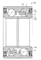
図11および図12を参照して、車輪用転がり軸受である複列アンギュラ玉軸受110は、ホイール111とタイヤ112よりなる車輪120(駆動輪)を支持するハブ輪113などの回転側部材を、ナックル114などの固定側部材に対して回転可能に支持するものである。
Referring to FIGS. 11 and 12, a double-row angular
この複列アンギュラ玉軸受110は、外輪11と、内輪12と、玉13と、保持器14と、シール部材15と、磁気エンコーダ115とを主に有している。内輪12はハブ輪113の外周面に嵌合されており、外輪11はナックル114の内周面に嵌合されている。
This double-row
外輪11は1つの部材から構成されている。内輪12は2つの部材から構成されている。複数の玉13は、複列に配置されている。複数の玉13は、外輪転走面11Aおよび内輪転走面12Aの各々に玉転走面13Aにおいて接触し、くし型形状の保持器14により周方向に所定のピッチで配置されることにより円環状の軌道上に転動自在に保持されている。これにより、外輪11と内輪12とは互いに相対的に回転可能となっている。
The
玉13と外輪11との接触点と、玉13と内輪12との接触点とを結ぶ直線は、ラジアル方向(複列アンギュラ玉軸受110の回転軸に垂直な方向)に対して角度をなしている。そのため、ラジアル方向の荷重が負荷されると、アキシャル方向(複列アンギュラ玉軸受110の回転軸の方向)への分力が生じる。隣り合う玉13の玉13と外輪11との接触点と玉13と内輪12との接触点とを結ぶ直線は、分力を相殺するように逆向きに配置されている。
A straight line connecting the contact point between the
外輪11の内径と内輪12の外径にはシール部材15が挿入されている。このシール部材15により、複列アンギュラ玉軸受内からの油の漏れや複列アンギュラ玉軸受外からの異物や水分の侵入を防止することができる。
磁気エンコーダ115は、内輪12の端部外径に圧入されており、その状態で周方向に多極磁化された磁性部材が、ナックル114に固定された磁気センサ116と近接対峙している。これにより、車輪の回転速度を高精度に検出することができる。
The
次に、車輪120の動作について説明する。ナックル114などの固定側部材に対して、ハブ輪113などの回転側部材が回転することにより、車輪120が回転する。
Next, the operation of the
本発明の一実施の形態における車輪用転がり軸受の製造方法は、上記モータ用転がり軸受の製造方法と成形工程を除き同様である。成形工程では、図12に示される外輪11、内輪12、玉13、などの概略形状に成形された鋼製部材が作製される。これ以外の製造方法については説明を繰り返さない。
The method for manufacturing a wheel rolling bearing according to an embodiment of the present invention is the same as the method for manufacturing the rolling bearing for motor, except for the molding step. In the forming step, steel members formed into a schematic shape such as the
なお、上記本発明の一実施の形態においては、一例として、モータ用転がり軸受、工作機械主軸用転がり軸受、車輪用転がり軸受、グリース深溝玉軸受、アンギュラ玉軸受、円筒ころ軸受、複列アンギュラ玉軸受およびこれらが備える軌道部材および転動体について説明した。本発明の転がり軸受およびその軸受部材は、これらに限られず、他の形態の転がり軸受およびそれが備える軌道部材および転動体であってもよい。たとえば、他の形態の転がり軸受は、ラジアル軸受であってもよく、スラスト軸受であってもよい。軌道部材は、外輪、内輪などを含む。また、転動体は、内輪、外輪、軌道盤との間で転走面を成していてもよい。転動体は、玉、円筒ころ、円錐ころなどを含む。 In the embodiment of the present invention described above, as an example, a rolling bearing for a motor, a rolling bearing for a machine tool spindle, a rolling bearing for a wheel, a grease deep groove ball bearing, an angular contact ball bearing, a cylindrical roller bearing, a double row angular contact ball The bearings and the race members and rolling elements included in the bearings have been described. The rolling bearing and the bearing member thereof according to the present invention are not limited to these, and may be other forms of rolling bearings, raceway members and rolling elements included therein. For example, the rolling bearing of another form may be a radial bearing or a thrust bearing. The track member includes an outer ring and an inner ring. Moreover, the rolling element may form a rolling surface between the inner ring, the outer ring, and the bearing disc. The rolling elements include balls, cylindrical rollers, tapered rollers and the like.
なお、軌道部材としての外輪、内輪および転動体としての玉の素材として、JIS規格SUJ2で説明したが、JIS規格SUJ2の相当材である52100(AISIまたはSAE規格)、100Cr6(DIN規格)、GCr15(GSB規格)も適用することができる。 In addition, as the material of the outer ring as the race member, the inner ring and the ball as the rolling element, the JIS standard SUJ2 has been described. (GSB standard) can also be applied.
さらに、本発明の一実施の形態の別の例について説明する。
本発明の一実施の形態の転がり軸受は、オルタネータ用転がり軸受に適用されてもよい。以下、本発明の一実施の形態の転がり軸受の別の例としてオルタネータ用転がり軸受について説明し、これを備えたオルタネータの構成について説明する。
Furthermore, another example of the embodiment of the present invention will be described.
The rolling bearing according to one embodiment of the present invention may be applied to an alternator rolling bearing. Hereinafter, an alternator rolling bearing will be described as another example of the rolling bearing according to the embodiment of the present invention, and the configuration of the alternator including the same will be described.
図13を参照して、本発明の一実施の形態におけるオルタネータ200は、シャフト(主軸)201と、ロータ202と、ステータ203と、プーリ204と、ハウジング205と、オルタネータ用転がり軸受であるグリース封入深溝玉軸受1とを主に有している。
Referring to FIG. 13, an
ロータ202を取り囲むようにハウジング205が配置されている。ロータ202の中央部を貫通し、ハウジング205の壁面を貫通するようにシャフト201が配置されている。ハウジング205の内部において、ロータ202の外周面に対向するようにステータ203が配置されている。
A
シャフト201の一方端部の外周面の一部と対向するようにハウジング205が配置されている。シャフト201とハウジング205との間にはオルタネータ用転がり軸受であるグリース封入深溝玉軸受1が配置されている。グリース封入深溝玉軸受1によってシャフト201がハウジング205に対して回転可能に支持されている。シャフト201の一方端部の先端部には、ハウジング205の外部において、円環状の形状を有するプーリ204が取り付けられている。プーリ204の外周面には、図示していない伝動ベルトが掛けられる係合溝206が設けられている。
A
このオルタネータ用転がり軸受であるグリース封入深溝玉軸受1は、上記本発明の一実施の形態におけるモータ用転がり軸受としてのグリース封入深溝玉軸受1と同様の構成を有している。
The grease-enclosed deep
オルタネータ用転がり軸受であるグリース封入深溝玉軸受1は、図示しないエンジンなどの動力源で発生した動力を利用して動作するオルタネータ200において、この動力により回転駆動されるシャフト201を隣接して配置されるハウジング205に対して回転自在に支持する、たとえば自動車用の電装・補機用転がり軸受である。
A grease-filled deep
なお、一般的に、ロータ202とプーリ204との間において、シャフト201の一方端部に配置されたグリース封入深溝玉軸受1は、フロント軸受と呼ばれる。また、シャフト201の他方端部に配置されたグリース封入深溝玉軸受1は、リア軸受と呼ばれる。曲げモーメントなどの応力が大きいフロント軸受のグリース封入深溝玉軸受1のほうが、リア軸受のグリース封入深溝玉軸受1より、水素脆性はく離が生じやすい。
In general, the grease-filled deep
次にオルタネータ200の動作について説明する。係合溝206の形成されたプーリ204の外周面には、図示しないエンジンなどの動力源からの動力によって回転する図示しない伝達ベルトが掛けられる。この伝達ベルトが回転することにより、プーリ204は、ハウジング205に対してグリース封入深溝玉軸受1により軸支されたシャフト201と一体に、シャフト201の軸まわりに回転する。ロータ202は、シャフト201と一体にシャフト201の軸まわりに回転する。このとき、ロータ202は、ロータ202の外周面に対向し、ハウジング205に固定されて配置されたステータ203に対して相対的に回転する。その結果、ロータ202とステータ203との間の電磁誘導作用によりステータ203のコイルに起電力が発生する。
Next, the operation of the
このオルタネータ用転がり軸受であるグリース封入深溝玉軸受1の製造方法は、上記本発明の一実施の形態におけるモータ用転がり軸受としてのグリース封入深溝玉軸受1の製造方法と同様である。
The manufacturing method of the grease-enclosed deep
オルタネータ用転がり軸受は、急加減速条件下で接触要素間にすべりが生じる影響により水素脆性起因の早期はく離が起きやすい。また、通電の影響で水素脆性起因の早期はく離が起きることがある。また、昨今の省スペース化に伴い、オルタネータを含む電装補機部品を駆動するベルトはサーペンタイン化されている。ここでサーペンタイン化とは、一本のベルトで複数の補機部品が駆動されることをいう。サーペンタイン化することにより、補機部品毎に別のベルトは不要になるため省スペース化が可能となる。サーペンタイン化に伴い、負荷荷重が増加する傾向および荷重変動が大きくなる傾向であるため、従来よりもすべりが誘発されやすくなる。 Alternator rolling bearings are prone to early peeling due to hydrogen embrittlement due to the effect of slippage between contact elements under rapid acceleration / deceleration conditions. In addition, early peeling due to hydrogen embrittlement may occur due to the influence of electricity. Further, with recent space savings, belts for driving electrical accessory parts including alternators have been made serpentine. Here, serpentine formation means that a plurality of accessory parts are driven by a single belt. By using serpentine, a separate belt is not required for each accessory part, so that space can be saved. With serpentine formation, the load tends to increase and the load fluctuation tends to increase, so that slip is more likely to be induced than in the prior art.
オルタネータ用転がり軸受であるグリース封入深溝玉軸受1は、内輪回転で使用されるため、外輪11の一部の負荷回転が多い。そのため、その外輪11の一部に水素脆性起因の早期はく離が起きやすいので、外輪11に本発明の一実施の形態の軸受部材が適用されることが好ましい。
Since the grease-filled deep
また、本発明の一実施の形態の転がり軸受は、プーリ用転がり軸受に適用されてもよい。以下、本発明の一実施の形態の転がり軸受の別の例としてプーリ用転がり軸受について説明し、これを備えたプーリの構成について説明する。 Moreover, the rolling bearing of one embodiment of the present invention may be applied to a pulley rolling bearing. Hereinafter, a pulley rolling bearing will be described as another example of a rolling bearing according to an embodiment of the present invention, and a configuration of a pulley including the same will be described.
図14を参照して、本発明の一実施の形態におけるプーリ210は、プーリ本体211と、プーリ用転がり軸受であるグリース封入深溝玉軸受1とを主に有している。
Referring to FIG. 14, a
プーリ本体211は、円環状の形状を有している。プーリ本体211の外周面には、図示していない伝動ベルトが掛けられる伝動ベルト掛けまわし部212が設けられている。プーリ本体211の内径側の中央部に、シャフト(主軸)218が貫通するための貫通孔213が形成されている。この貫通孔213の内周面とグリース封入深溝玉軸受1の外輪11とが接触するように、プーリ本体211にグリース封入深溝玉軸受1が嵌め込まれている。
The
より具体的には、プーリ本体211は、内周面に貫通孔を有する円筒状の内周円筒部214と、内周円筒部214の幅方向(軸方向)における一方の端部から径方向外側に延びるフランジ部215と、フランジ部215から幅方向(軸方向)に延びる外周円筒部216と、内周円筒部214の幅方向(軸方向)における他方の端部から径方向内側に延びる鍔部217とを有している。グリース封入深溝玉軸受1の外輪11がプーリ本体211の内周円筒部214および鍔部217に接触するように嵌め込まれている。
More specifically, the
また、グリース封入深溝玉軸受1の内輪12には、シャフト218が嵌め込まれることにより取り付けられている。
Further, a
このプーリ用転がり軸受であるグリース封入深溝玉軸受1は、上記本発明の一実施の形態におけるモータ用転がり軸受としてのグリース封入深溝玉軸受1と同様の構成を有している。
The grease-enclosed deep
プーリ用転がり軸受であるグリース封入深溝玉軸受1は、図示しないエンジンなどの動力源で発生した動力を利用して動作するプーリ210において、この動力により回転駆動されるプーリ本体211をプーリ210を貫通して配置されるシャフト218に対して回転自在に支持する、たとえば自動車用の電装・補機用転がり軸受である。
The grease-enclosed deep
次にプーリ210の動作について説明する。伝動ベルト掛けまわし部212の形成されたプーリ本体211の外周面には、図示しないエンジンなどの動力源からの動力によって回転する図示しない伝達ベルトが掛けられる。この伝達ベルトが回転することにより、プーリ210は、グリース封入深溝玉軸受1により軸支されたシャフト218と一体に、シャフト218の軸まわりに回転する。これにより、プーリ210は、伝動ベルトが掛けられる軸同士の距離が固定されているような場合に、伝動ベルトに張力を与えるテンショナーとしての機能を果たし得る。また、これにより、プーリ210は、障害となるエンジンルームないの各種装置との接触の回避などの目的で伝動ベルトの走行方向を変えるためのアイドラーとしての機能を果たし得る。
Next, the operation of the
このプーリ用転がり軸受であるグリース封入深溝玉軸受1の製造方法は、上記本発明の一実施の形態におけるモータ用転がり軸受としてのグリース封入深溝玉軸受1の製造方法と同様である。
The manufacturing method of the grease-enclosed deep
プーリ用転がり軸受は、特にすべりや通電の影響で水素脆性起因の早期はく離が起きることがある。また、昨今の省スペース化に伴い、プーリを含む電装補機部品を駆動するベルトはサーペンタイン化されている。負荷荷重が増加する傾向および荷重変動が大きくなる傾向にあって、サーペンタイン化によって従来よりもすべりが誘発されやすくなる。 Rolling bearings for pulleys may be separated at an early stage due to hydrogen embrittlement, especially due to the effects of sliding and energization. In addition, with recent space savings, belts for driving electrical accessory parts including pulleys have been made serpentine. The load load tends to increase and the load fluctuation tends to increase, and slipping is more easily induced by serpentine formation.
プーリ用転がり軸受であるグリース封入深溝玉軸受1は、外輪回転で使用されるため、内輪12の一部の負荷回転が多い。そのため、その内輪12の一部に水素脆性起因の早期はく離が起きやすいので、内輪12に本発明の一実施の形態の軸受部材が適用されることが好ましい。
Since the grease-enclosed deep
また、本発明の一実施の形態の転がり軸受は、カーエアコン電磁クラッチプーリ用転がり軸受に適用されてもよい。以下、本発明の一実施の形態の転がり軸受の別の例としてカーエアコン電磁クラッチプーリ用転がり軸受について説明し、これを備えたカーエアコン電磁クラッチプーリ機構付きコンプレッサの構成について説明する。 Moreover, the rolling bearing of one embodiment of the present invention may be applied to a rolling bearing for a car air conditioner electromagnetic clutch pulley. Hereinafter, a rolling bearing for a car air conditioner electromagnetic clutch pulley will be described as another example of a rolling bearing according to an embodiment of the present invention, and the configuration of a compressor with a car air conditioner electromagnetic clutch pulley mechanism including the same will be described.
図15を参照して、このコンプレッサは、片斜板タイプの斜板式コンプレッサ220とコンプレッサ用プーリ機構230とを備えている。
Referring to FIG. 15, the compressor includes a swash plate type
まず、片斜板タイプの斜板式コンプレッサ220について説明する。
片斜板タイプの斜板式コンプレッサ220は、ハウジング221と、そのハウジング221にたとえばねじ止め固定されたプーリ用軸受支持部材234と、主軸223と、その主軸223に取り付けられた回転部材225と、その回転部材225の回転に伴って揺動運動をする斜板222と、その斜板222に連結されたピストンロッド226と、そのピストンロッド226の反対側に連結されたピストン224とを有している。
First, the swash plate type
A swash plate type
回転部材225とプーリ用軸受支持部材234との間には、スラスト荷重を受ける支持構造として複列のスラスト針状ころ軸受よりなる回転部材・プーリ支持部材軸受231が配置されている。また斜板222と回転部材225との間には、スラスト荷重を受ける支持構造として複列のスラスト針状ころ軸受よりなる斜板支持軸受233が配置されている。
Between the
このコンプレッサ220では、主軸223の回転に伴って回転部材225が回転し、それにより斜板222が揺動運動する。この斜板222の揺動運動によりピストンロッド226が往復運動して、ピストンロッド226に連結されたピストン224がシリンダ内を往復運動する。
In the
次に、コンプレッサ用プーリ機構230について説明する。
コンプレッサ220のハウジング221にプーリ用軸受支持部材234がねじ止め固定されている。また、プーリ用軸受支持部材234にクラッチ用電磁石235が固着されている。他方、主軸223の軸端に動力伝達部材236が嵌着されている。プーリ用転がり軸受であるグリース封入深溝玉軸受1の外周にカーエアコン電磁クラッチプーリ237が嵌合されている。
Next, the
A pulley bearing
主軸223とプーリ用軸受支持部材234との間には、主軸支持軸受232が配置されている。またカーエアコン電磁クラッチプーリ237の内周面とプーリ用軸受支持部材234との間には、カーエアコン電磁クラッチプーリ用転がり軸受であるグリース封入深溝玉軸受1が配置されている。
A main shaft support bearing 232 is disposed between the
このカーエアコン電磁クラッチプーリ用転がり軸受であるグリース封入深溝玉軸受1は、上記本発明の一実施の形態におけるモータ用転がり軸受としてのグリース封入深溝玉軸受1と同様の構成を有している。
The grease-enclosed deep
このプーリ機構230では、クラッチ用電磁石235を励磁しまたは非励磁にすることによって、図示していない駆動力によって回転しているカーエアコン電磁クラッチプーリ237の回転駆動力が主軸223に伝達されてコンプレッサが動作したり、またはカーエアコン電磁クラッチプーリ237の回転駆動力が主軸223に伝達されなくなってコンプレッサが動作を停止したりする。
In the
次に、コンプレッサ用軸受について説明する。
コンプレッサ用軸受は、コンプレッサ220に使用されるコンプレッサ用軸受とプーリ機構230に使用されるコンプレッサ用軸受とに大別される。
Next, the compressor bearing will be described.
The compressor bearing is roughly classified into a compressor bearing used for the
コンプレッサ220に使用されるコンプレッサ用軸受には、斜板222と回転部材225とを回転自在に支持する斜板支持軸受233、および回転部材225とプーリ用軸受支持部材234とを回転自在に支持する回転部材・プーリ支持部材軸受231が該当する。
The compressor bearing used in the
また、プーリ機構230に使用されるコンプレッサ用軸受には、主軸223とプーリ用軸受支持部材234とを回転自在に支持する主軸支持軸受232、およびカーエアコン電磁クラッチプーリ237とプーリ用軸受支持部材234とを回転自在に支持するカーエアコン電磁クラッチプーリ用転がり軸受であるグリース封入深溝玉軸受1が該当する。
The compressor bearings used in the
回転部材・プーリ支持部材軸受231および斜板支持軸受233には、スラスト針状ころ軸受が使用されている。このスラスト針状ころ軸受として、後述する図19に示すスラスト針状ころ軸受270が使用されてもよい。主軸支持軸受232には、針状ころ軸受または円筒ころ軸受が使用されている。この円筒ころ軸受として、図8に示す円筒ころ軸受20が使用されてもよい。カーエアコン電磁クラッチプーリ用転がり軸受であるグリース封入深溝玉軸受1には、図2に示すグリース封入深溝玉軸受が使用されている。カーエアコン電磁クラッチプーリ用転がり軸受には複列アンギュラ玉軸受が使用されてもよい。複列アンギュラ玉軸受として、図12に示す複列アンギュラ玉軸受110が使用されてもよい。
Thrust needle roller bearings are used for the rotary member / pulley support member bearing 231 and the swash
コンプレッサ220に使用されるコンプレッサ用軸受には、ピストン224の衝撃に耐えるために、ころ径の大きいスラスト針状ころ軸受が使用されている。また、スラスト針状ころ軸受では、針状ころと軌道面とが線接触する構造であって、針状ころと転がり線接触する軌道面は、軸受の回転中心から外径側に向かうほど周速度は大きくなる。
A thrust needle roller bearing having a large roller diameter is used for the compressor bearing used in the
コンプレッサ220に使用されるコンプレッサ用軸受であるスラスト針状ころ軸受は、通常の軸受のような軌道盤を有していないで、複数の針状ころが保持器に保持されて軌道面に線接触して回転する。斜板支持軸受233においては、斜板222および回転部材225がそれぞれ軌道面を有する部材となり、回転部材・プーリ支持部材軸受231においては、回転部材225およびプーリ用軸受支持部材234がそれぞれ軌道面を有する部材となる。
A thrust needle roller bearing, which is a compressor bearing used in the
このカーエアコン電磁クラッチプーリ用転がり軸受であるグリース封入深溝玉軸受1の製造方法は、上記本発明の一実施の形態におけるモータ用転がり軸受としてのグリース封入深溝玉軸受1の製造方法と同様である。
The manufacturing method of the grease-enclosed deep
カーエアコン電磁クラッチプーリ用転がり軸受は、特にすべりの影響で水素脆性起因の早期はく離が起きることがある。また、昨今の省スペース化に伴い、カーエアコンを含む電装補機部品を駆動するベルトはサーペンタイン化されている。負荷荷重が増加する傾向および荷重変動が大きくなる傾向にあって、サーペンタイン化によって従来よりもすべりが誘発されやすくなる。 Rolling bearings for car air conditioner electromagnetic clutch pulleys may cause early peeling due to hydrogen embrittlement, particularly due to the effect of sliding. In addition, with recent space savings, belts for driving electrical accessory parts including car air conditioners have been made serpentine. The load load tends to increase and the load fluctuation tends to increase, and slipping is more easily induced by serpentine formation.
カーエアコン電磁クラッチプーリ用転がり軸受であるグリース封入深溝玉軸受1は、外輪回転で使用されるため、内輪12の一部の負荷回転が多い。そのため、その内輪12の一部に水素脆性起因の早期はく離が起きやすいので、内輪12に本発明の一実施の形態の軸受部材が適用されることが好ましい。
Since the grease-enclosed deep
また、本発明の一実施の形態の転がり軸受は、無段変速機用転がり軸受に適用されてもよい。以下、本発明の一実施の形態の転がり軸受の別の例として無段変速機用転がり軸受について説明し、これを備えた無断変速機の構成について説明する。 Further, the rolling bearing according to one embodiment of the present invention may be applied to a continuously variable transmission rolling bearing. Hereinafter, a rolling bearing for a continuously variable transmission will be described as another example of a rolling bearing according to an embodiment of the present invention, and the configuration of a continuously variable transmission provided with the same will be described.
図16を参照して、本発明の一実施の形態における無段変速機の一例として、ベルト式無段変速機240について説明する。ベルト式無段変速機240は、プライマリプーリ軸(プーリ軸)241と、プライマリプーリ242と、セカンダリプーリ軸243と、セカンダリプーリ(プーリ軸)244と、無端ベルト245と、ケーシング(ハウジング)246と、無段変速機用転がり軸受であるグリース封入深溝玉軸受1とを主に有している。
With reference to FIG. 16, a belt-type continuously
プライマリプーリ軸241にはプライマリプーリ242が設けられている。プライマリプーリ242はプライマリプーリ固定シーブ242aとプライマリプーリ可動シーブ242bとを有している。プライマリプーリ固定シーブ242aはプライマリプーリ軸241と一体に構成されている。プライマリプーリ可動シーブ242bは、プライマリプーリ軸241に貫通されており、プライマリプーリ軸241の軸方向にスライド可能に構成されている。プライマリプーリ軸241の一方端は図示しないクラッチに接続されている。プライマリプーリ軸241の他方端はケーシング246に固定された無段変速機用転がり軸受であるグリース封入深溝玉軸受1に回転可能に支持されている。
A
セカンダリプーリ軸243にはセカンダリプーリ244が設けられている。セカンダリプーリ244はセカンダリプーリ固定シーブ244aとセカンダリプーリ可動シーブ244bとを有している。セカンダリプーリ固定シーブ244aはセカンダリプーリ軸243と一体に構成されている。セカンダリプーリ可動シーブ244bは、セカンダリプーリ軸243に貫通されており、セカンダリプーリ軸243の軸方向にスライド可能に構成されている。セカンダリプーリ軸243は、図示しない歯車機構の歯車が取り付けられた一方端を別の軸受で支持されている。セカンダリプーリ軸243の他方端はケーシング246に固定された無段変速機用転がり軸受であるグリース封入深溝玉軸受1に回転可能に支持されている。
A
プライマリプーリ242とセカンダリプーリ244との間にはV字状の無端ベルト245が張り渡されている。プライマリプーリ242は、プライマリプーリ可動シーブ242bがスライドすることによりプライマリプーリ固定シーブ242aとプライマリプーリ可動シーブ242bとの幅(プライマリプーリ幅)が変動可能に構成されている。
A V-shaped
セカンダリプーリ244は、セカンダリプーリ可動シーブ244bがスライドすることによりセカンダリプーリ固定シーブ244aとセカンダリプーリ可動シーブ244bとの幅(セカンダリプーリ幅)が変動可能に構成されている。プライマリプーリ幅およびセカンダリプーリ幅が変動することにより、プライマリプーリ242およびセカンダリプーリ244は、無端ベルト245が張り渡されているそれぞれの径方向の位置が変動するように構成されている。
The
次に、ベルト式無段変速機240の動作について説明する。プライマリプーリ軸241に図示しないエンジンからクラッチを介して駆動力が伝達される。プライマリプーリ幅およびセカンダリプーリ幅が変動されることにより、無端ベルト245が張り渡されているそれぞれの径方向の位置が変動される。これにより、プライマリプーリ軸241の駆動力がセカンダリプーリ軸243に無段変速で伝達される。セカンダリプーリ軸243から歯車機構とデファレンシャルを介して車軸に駆動力が伝達される。これにより、無段変速が達成される。
Next, the operation of the belt type continuously
この無段変速機用転がり軸受であるグリース封入深溝玉軸受1の製造方法は、上記本発明の一実施の形態におけるモータ用転がり軸受としてのグリース封入深溝玉軸受1の製造方法と同様である。
The manufacturing method of the grease-enclosed deep
無段変速機用転がり軸受については、プーリ部の回転精度を確保するため、軸受のガタ(アキシャルすきま)を抑えることが重要であり、従来は、軸受内外輪の溝曲率を小さくし、軸受のアキシャルすきまを抑える手法が採用されてきた。しかし軸受内外輪の溝曲率が小さく設定されると軸受運転時の差動すべりが大きくなり、その影響で水素脆性起因の早期はく離が起きやすくなる。 For rolling bearings for continuously variable transmissions, it is important to reduce the backlash (axial clearance) of the bearings in order to ensure the rotational accuracy of the pulley. Conventionally, the groove curvature of the bearing inner and outer rings is reduced, A technique for reducing the axial clearance has been adopted. However, if the groove curvature of the inner and outer rings of the bearing is set to be small, the differential slip during the operation of the bearing becomes large, and the early peeling due to hydrogen embrittlement is likely to occur due to the influence.
無段変速機用転がり軸受であるグリース封入深溝玉軸受1は、内輪回転で使用されるため、外輪11の一部の負荷回転が多い。そのため、その外輪11の一部に水素脆性起因の早期はく離が起きやすいので、外輪11に本発明の一実施の形態の軸受部材が適用されることが好ましい。
Since the grease-enclosed deep
また、本発明の一実施の形態の転がり軸受は、針状ころ軸受に適用されてもよい。針状ころ軸受は、急加減速などのすべりを伴う条件下で使用されると、潤滑剤が分離して水素が発生し、それが鋼中に侵入することで早期はく離が起こることがある。今後、コンパクト化や省エネ化に対応するため、針状ころ軸受の使用条件はますます厳しくなる傾向にあり、耐水素ぜい性に優れたものが必要になると予想される。 Moreover, the rolling bearing of one embodiment of the present invention may be applied to a needle roller bearing. When a needle roller bearing is used under conditions involving sliding such as rapid acceleration / deceleration, hydrogen is generated by separation of the lubricant, which may cause premature separation due to penetration into the steel. In the future, in order to cope with downsizing and energy saving, the use conditions of needle roller bearings will tend to become stricter, and it is expected that those with excellent hydrogen embrittlement resistance will be required.
本発明の一実施の形態の転がり軸受の別の例である針状ころ軸受の一例としてシェル形針状ころ軸受について説明する。 A shell-type needle roller bearing will be described as an example of a needle roller bearing which is another example of the rolling bearing according to the embodiment of the present invention.
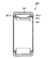
図17を参照して、シェル形針状ころ軸受250は、軌道部材としてのシェル外輪251と、複数の転動体としての針状ころ252と、保持器253とを備えている。シェル外輪251は内径面に軌道面を有している。シェル外輪251は軸方向の両端部に、径方向の内径側に突出する鍔部251aを有している。針状ころ252は軌道面に沿って配置されている。保持器253は隣接する針状ころ252の間隔を保持するように構成されている。保持器253はシェル外輪251の鍔部251aの軸方向の内側に配置されている。なお、シェル外輪251はオープンエンド形であってもよく、またクローズエンド形であってもよい。
Referring to FIG. 17, shell
本発明の一実施の形態におけるシェル形針状ころ軸受250の製造方法は、上記本発明の一実施の形態におけるモータ用転がり軸受の製造方法と成形工程を除き同様である。成形工程では、図17に示されるシェル外輪251、針状ころ252、保持器253などの概略形状に成形された鋼製部材が作製される。これ以外の製造方法については説明を繰り返さない。
The manufacturing method of the shell
シェル形針状ころ軸受は、特に、電磁クラッチの切り替えにより急加減速する自動車のエアーコンプレッサの支持に用いられる場合、始動時の加速が早いABSポンプの支持に用いられる場合、汎用エンジンのコンロッドの大端に用いられる場合などに、転動体にすべりが生じやすく、水素脆性起因の早期はく離が起きることがある。 Shell-shaped needle roller bearings are used for supporting air compressors of automobiles that accelerate and decelerate rapidly by switching electromagnetic clutches, and when used for supporting ABS pumps that accelerate quickly when starting. When used at the large end, the rolling elements are likely to slip, and early peeling due to hydrogen embrittlement may occur.
また、本発明の一実施の形態の転がり軸受の別の例である針状ころ軸受の一例としてソリッド形針状ころ軸受について説明する。 A solid needle roller bearing will be described as an example of a needle roller bearing which is another example of the rolling bearing according to the embodiment of the present invention.
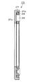
図18を参照して、ソリッド形針状ころ軸受260は、軌道部材としての外輪261と、複数の転動体としての針状ころ252と、保持器253とを備えている。外輪261は肉厚に形成され、かつ軸方向の両端部に、径方向の内径側に突出する鍔部261aを有している。保持器253は外輪261の鍔部261aの径方向の内径側に配置されている。
Referring to FIG. 18, the solid
本発明の一実施の形態におけるソリッド形針状ころ軸受260の製造方法は、上記本発明の一実施の形態におけるモータ用転がり軸受の製造方法と成形工程を除き同様である。成形工程では、図18に示される外輪261、針状ころ252、保持器253などの概略形状に成形された鋼製部材が作製される。これ以外の製造方法については説明を繰り返さない。
The manufacturing method of the solid
ソリッド形針状ころ軸受は、特に、電磁クラッチの切り替えにより急加減速する自動車のエアーコンプレッサの支持に用いられる場合、始動時の加速が早いトランスミッションの支持に用いられる場合、汎用エンジンのコンロッドの大端に用いられる場合などに、接触要素間にすべりが生じやすく、水素脆性起因の早期はく離が起きることがある。 Solid needle roller bearings, especially when used to support automobile air compressors that accelerate and decelerate suddenly by switching electromagnetic clutches, when used to support transmissions that accelerate quickly during start-up, are large in connecting rods for general-purpose engines. When used at the end, slippage between contact elements is likely to occur, and early peeling due to hydrogen embrittlement may occur.
また、本発明の一実施の形態の転がり軸受の別の例である針状ころ軸受の一例としてスラスト針状ころ軸受について説明する。 A thrust needle roller bearing will be described as an example of a needle roller bearing which is another example of the rolling bearing according to the embodiment of the present invention.
図19を参照して、スラスト針状ころ軸受270は、軌道部材としての軌道盤271と、複数の転動体としての針状ころ252と、保持器253とを備えている。軌道盤271の外形側には針状ころ252が転走する軌道盤外径部271aが形成されている。軌道盤271の先端部には径方向の内径側に突出する軌道盤突出部271bが形成されている。軌道盤突出部271bの軸方向の内側に保持器253の先端部が配置されることにより、スラスト針状ころ軸受270は針状ころ252および保持器253が軌道盤271と分離しないように構成されている。針状ころ252は軌道面に沿って径方向に配置されている。保持器253は隣接する針状ころ252の間隔を周方向に保持するように構成されている。
Referring to FIG. 19, the thrust
本発明の一実施の形態におけるスラスト針状ころ軸受270の製造方法は、上記本発明の一実施の形態におけるモータ用転がり軸受の製造方法と成形工程を除き同様である。成形工程では、図19に示される軌道盤271、針状ころ252、保持器253などの概略形状に成形された鋼製部材が作製される。これ以外の製造方法については説明を繰り返さない。
The manufacturing method of the thrust
スラスト針状ころ軸受は、転動体内外の周速差により、運転中は絶えず転動輪との間にすべりが生じており、水素脆性起因の早期はく離が起きることがある。 The thrust needle roller bearing is constantly slipped from the rolling wheel during operation due to the difference in peripheral speed between the inside and outside of the rolling element, and may cause early separation due to hydrogen embrittlement.
また、本発明の一実施の形態の針状ころ軸受は、保持器付き針状ころ軸受であってもよい。図20を参照して、保持器付き針状ころ軸受280の保持器253は金属材料で構成されていてもよい。金属材料製の保持器253は高い強度を有している。また、図21を参照して、保持器付き針状ころ軸受280の保持器253は高分子材料で構成されていてもよい。高分子材料製の保持器253は形状の自由度が高く、組み込みが容易である。
Further, the needle roller bearing according to the embodiment of the present invention may be a needle roller bearing with a cage. Referring to FIG. 20,
保持器付き針状ころ軸受は、特に、始動時の加速が速い自動車のトランスミッションのアイドラー軸受として用いられる場合、CVTの遊星ピニオン支持軸受として用いられる場合、二輪エンジンや汎用エンジンのコンロッドの大端用軸受として用いられる場合などに、転動体にすべりが生じやすく、水素脆性起因の早期はく離が起きることがある。 Needle roller bearings with cages, especially when used as idler bearings in automobile transmissions that accelerate quickly at start-up, when used as planetary pinion support bearings for CVT, for large-end connecting rods of two-wheeled engines and general-purpose engines When used as a bearing or the like, the rolling elements are likely to slip, and early peeling due to hydrogen embrittlement may occur.
次に本発明の一実施の形態の作用効果について説明する。
本発明の一実施の形態の転がり軸受は、円環状の軌道を有する軌道部材としての外輪11、内輪12と、軌道部材としての外輪11、内輪12に接触し、円環状の軌道上に転動自在に配置された複数の転動体としての玉13とを備えている。軌道部材としての外輪11、内輪12および転動体としての玉13、円筒ころ14のうち少なくとも1つの軸受部材は、JIS規格SUJ2からなっている。
Next, the function and effect of the embodiment of the present invention will be described.
A rolling bearing according to an embodiment of the present invention is in contact with an
本発明の一実施の形態の転がり軸受によれば、軌道部材としての外輪11、内輪12および転動体としての玉13のうち少なくとも1つの軸受部材は、焼入れされている。軌道部材としての外輪11、内輪12および転動体としての玉13のうち少なくとも1つの軸受部材は、窒化処理された転走面11A,12A,13Aを有している。軸受部材の転走面11A,12A,13Aに窒化処理を施すことによって軸受部材が塑性変形しにくくなる。軸受部材の転走面11A,12A,13Aに窒化処理を施すことによって軸受部材が塑性変形しにくくなることで、軸受部材の耐水素脆性が向上する。
According to the rolling bearing of an embodiment of the present invention, at least one bearing member among the
本発明の一実施の形態の転がり軸受によれば、軌道部材としての外輪11、内輪12および転動体としての玉13のうち少なくとも1つの軸受部材に直径19.05mmのSUJ2製標準転がり軸受用鋼球を荷重3.18kNで押し付け、10秒間保持した後に除荷することにより軸受部材に形成される圧痕の深さが0.2μm以下である。圧痕深さは、目安として0.2μm以下であれば塑性変形しにくいといえる。そこで、焼戻温度と圧痕深さとの関係を詳細に調査したところ、240℃以上300℃以下で焼戻処理を施せば、軸受部材に直径19.05mmのSUJ2製標準転がり軸受用鋼球を荷重3.18kNで押し付け、10秒間保持した後に除荷することにより軸受部材に形成される圧痕の深さが0.2μm以下となることがわかった。
According to the rolling bearing of an embodiment of the present invention, SUJ2 standard rolling bearing steel having a diameter of 19.05 mm is provided on at least one bearing member among the
本発明の一実施の形態の転がり軸受によれば、軌道部材としての外輪11、内輪12および転動体としての玉13のうち少なくとも1つの軸受部材の転走面のロックウェルCスケール硬さがHRC61.2以上HRC63.3以下である。焼戻温度240℃以上300℃以下の範囲における軸受部材の転走面のロックウェルCスケール硬さは、HRC61.2以上HRC63.3以下となることがわかった。
According to the rolling bearing of one embodiment of the present invention, the Rockwell C scale hardness of the rolling surface of at least one bearing member among the
したがって、窒化処理された転走面11A,12A,13Aを有する軸受部材に焼戻温度240℃以上300℃以下で焼戻しを施すことにより、塑性変形しにくくして原子空孔を生成しにくくすることができる。これにより、耐水素脆性を向上することができるので水素脆性起因の早期はく離を抑制できる。 Therefore, by tempering the bearing member having the nitriding rolling surfaces 11A, 12A, and 13A at a tempering temperature of 240 ° C. or higher and 300 ° C. or lower, it is difficult to plastically deform and make it difficult to generate atomic vacancies. Can do. Thereby, since hydrogen embrittlement resistance can be improved, early peeling due to hydrogen embrittlement can be suppressed.
また、本発明の一実施の形態の転がり軸受によれば、転走面11A,12A,13Aの表面窒化濃度が0.05質量%以上0.4質量%以下である。 Moreover, according to the rolling bearing of one embodiment of the present invention, the surface nitriding concentration of the rolling surfaces 11A, 12A, 13A is 0.05% by mass or more and 0.4% by mass or less.
転走面11A,12A,13Aの表面窒化濃度は0.05質量%未満では窒化による寿命向上の効果が十分に得られない。転走面11A,12A,13Aの表面窒化濃度が0.4質量%より大きいとCr炭窒化物が多く生成されるため焼入性に寄与するCr量が欠乏する。そのため、十分な焼入性が確保できない。転走面11A,12A,13Aの表面窒化濃度が0.05質量%以上0.4質量%以下とすることで、窒化による寿命向上の効果を十分に得ることができ、十分な焼入性を確保することもできる。 If the surface nitridation concentration of the rolling surfaces 11A, 12A, and 13A is less than 0.05% by mass, the effect of improving the life due to nitriding cannot be obtained sufficiently. If the surface nitriding concentration of the rolling surfaces 11A, 12A, and 13A is larger than 0.4% by mass, a large amount of Cr carbonitride is generated, so that the Cr amount contributing to hardenability is deficient. Therefore, sufficient hardenability cannot be ensured. By making the surface nitridation concentration of the rolling surfaces 11A, 12A, and 13A 0.05 mass% or more and 0.4 mass% or less, the effect of improving the life by nitriding can be sufficiently obtained, and sufficient hardenability can be obtained. It can also be secured.
また、本発明の一実施の形態の転がり軸受によれば、転動体として玉13は、窒化処理されていないJIS規格SUJ2であってもよい。この場合、玉13に直径19.05mmのSUJ2製標準転がり軸受用鋼球を荷重1.97kNで押し付け、10秒間保持した後に除荷することにより玉13に形成される圧痕の深さが0.2μm以下である。圧痕深さは、目安として0.2μm以下であれば塑性変形しにくいといえる。そこで、焼戻温度と圧痕深さとの関係を詳細に調査したところ、240℃以上280℃以下で焼戻処理を施せば、軸受部材に直径19.05mmのSUJ2製標準転がり軸受用鋼球を荷重1.97kNで押し付け、10秒間保持した後に除荷することにより玉13に形成される圧痕の深さが0.2μm以下となることがわかった。
Moreover, according to the rolling bearing of one embodiment of the present invention, the
したがって、窒化処理された転走面13Aを有していない玉13に焼戻温度を240℃以上280℃以下で焼戻しを施すことにより、塑性変形しにくくして原子空孔を生成しにくくすることができる。これにより、耐水素脆性を向上することができるので水素脆性起因の早期はく離を抑制できる。
Therefore, by tempering the
上記の転がり軸受において好ましくは、転動体全体のロックウェルCスケール硬さがHRC57.0以上HRC58.9以下である。焼戻温度240以上280以下の範囲における転動体全体のロックウェルCスケール硬さは、HRC57.0以上HRC58.9以下である。
In the rolling bearing described above, the Rockwell C scale hardness of the entire rolling element is preferably HRC57.0 or more and HRC58.9 or less. The Rockwell C scale hardness of the whole rolling element in the range of tempering
また、本発明の一実施の形態の転がり軸受によれば、転動体がセラミックスを含む材質よりなっていてもよい。これにより、転動体が水素脆性を示さないセラミックスを含む材質よりなっているため、耐水素脆性を向上することができるので水素脆性起因の早期はく離を抑制できる。 Moreover, according to the rolling bearing of one embodiment of the present invention, the rolling element may be made of a material containing ceramics. Thereby, since the rolling element is made of a material containing ceramics that does not exhibit hydrogen embrittlement, the hydrogen embrittlement resistance can be improved, so that early peeling due to hydrogen embrittlement can be suppressed.
また、本発明の一実施の形態の転がり軸受によれば、転動体を保持するための保持器をさらに備え、保持器が金属を含む材質よりなっていてもよい。これにより、通電が起きる条件下では、金属保持器の方が樹脂保持器よりも水素脆性起因の早期はく離が起きにくいので、水素脆性起因の早期はく離を抑制できる。 Moreover, according to the rolling bearing of one embodiment of the present invention, it may further include a cage for holding the rolling elements, and the cage may be made of a material containing metal. Thereby, under the condition where energization occurs, the metal cage is less likely to cause early peeling due to hydrogen embrittlement than the resin cage, and therefore, early peeling due to hydrogen embrittlement can be suppressed.
本発明の一実施の形態の転がり軸受の製造方法によれば、円環状の軌道を有する軌道部材としての外輪11、内輪12と、軌道部材としての外輪11、内輪12に接触し、円環状の軌道上に転動自在に配置された複数の転動体としての玉13とを備え、以下の工程を有している。軌道部材としての外輪11、内輪12および転動体としての玉13のうち少なくとも1つの軸受部材を、JIS規格SUJ2の材質からなるように準備する。軸受部材の転走面11A、12A、13Aに窒化処理を施して焼入れする。焼入れられた軸受部材を240℃以上300℃以下で焼戻しする。
According to the rolling bearing manufacturing method of an embodiment of the present invention, the
軸受部材の転走面11A、12A、13Aに窒化処理を施して焼入れすることにより軸受部材としての外輪11、内輪12、玉13が塑性変形しにくくする。軸受部材の転走面11A、12A、13Aに窒化処理を施して軸受部材が塑性変形しにくくなることで、軸受部材の耐水素脆性が向上する。
The
焼入れられた軸受部材を240℃以上300℃以下で焼戻しすることにより、軸受部材を塑性変形しにくくして原子空孔を生成しにくくすることができる。これにより、耐水素脆性を向上することができるので水素脆性起因の早期はく離を抑制できる。 By tempering the quenched bearing member at 240 ° C. or higher and 300 ° C. or lower, the bearing member is less likely to be plastically deformed, and it is possible to make it difficult to generate atomic vacancies. Thereby, since hydrogen embrittlement resistance can be improved, early peeling due to hydrogen embrittlement can be suppressed.
また、本発明の一実施の形態の転がり軸受の製造方法によれば、窒化処理は850℃の温度でRXガスにアンモニアガスを添加した雰囲気中で行われる。これにより、軸受部材の転走面11A、12A、13Aに十分な窒化処理を施して軸受部材が塑性変形しにくくなることで、軸受部材の耐水素脆性を向上することができる。 Further, according to the method for manufacturing a rolling bearing of one embodiment of the present invention, the nitriding treatment is performed at a temperature of 850 ° C. in an atmosphere in which ammonia gas is added to RX gas. Thereby, sufficient nitriding treatment is performed on the rolling surfaces 11A, 12A, and 13A of the bearing member to make the bearing member difficult to be plastically deformed, so that the hydrogen embrittlement resistance of the bearing member can be improved.
また、本発明の一実施の形態の転がり軸受によれば、図1に示すように、モータ90の主軸92と、主軸92の外周面に対向するように配置されるハウジング93とをさらに備え、主軸92をハウジング93に対して回転可能に支持してもよい。これにより、水素脆性起因の早期はく離を抑制できるので、軸受に水が混入する条件下、すべりを伴う条件下、通電が起きる条件下などの厳しい使用条件下においても長寿命なモータ用転がり軸受を提供することができる。
Further, according to the rolling bearing of the embodiment of the present invention, as shown in FIG. 1, the rolling bearing further includes a
また、本発明の一実施の形態の転がり軸受によれば、図6に示すように、工作機械100の主軸101と、主軸101の外周面に対向するように配置されるハウジング102とをさらに備え、主軸101をハウジング102に対して回転可能に支持してもよい。これにより、水素脆性起因の早期はく離を抑制できるので、軸受に水が混入する条件下、すべりを伴う条件下、通電が起きる条件下などの厳しい使用条件下においても長寿命な工作機械主軸用転がり軸受を提供することができる。また、高速回転時の発熱の原因となる軸受の摩擦トルクを低減するため潤滑油の油膜厚さを減少させた使用条件下においても長寿命な工作機械主軸用転がり軸受を提供することができる。
Further, according to the rolling bearing of the embodiment of the present invention, as shown in FIG. 6, the rolling bearing further includes a main shaft 101 of the
また、本発明の一実施の形態の転がり軸受によれば、一般的なグリース潤滑やエアオイル潤滑の場合でも有効であるが、少量の潤滑油で潤滑することにより軌道部材と転動体との間の油膜が薄い場合には特に有効である。 Further, according to the rolling bearing of one embodiment of the present invention, it is effective even in the case of general grease lubrication or air-oil lubrication, but by lubricating with a small amount of lubricating oil, between the race member and the rolling element. This is particularly effective when the oil film is thin.
上記の油量を削減しつつ、さらに低粘度の潤滑油を使用する潤滑装置40では、高速回転する工作機械主軸用転がり軸受で一般的に使用されるエアオイル潤滑よりさらに高速で運転されるためスターベーションが発生しやすい。そのためエアオイル潤滑に比べて油膜は薄くなっている。このため、この潤滑装置40では、水素が侵入しやすくなるので水素脆性起因の早期はく離の可能性が高くなる。しかしながら、本発明の一実施の形態の転がり軸受を適用することで、水素脆性起因の早期はく離を抑制できる。
The
また、上記の毛細管現象を利用する潤滑装置60では、通常のグリース潤滑以上の速度で運転する場合にはスターベーションが発生しやすい。このため、この潤滑装置60でも水素が侵入しやすくなるので水素脆性起因の早期はく離が発生する可能性が高くなる。しかしながら、本発明の一実施の形態の転がり軸受を適用することで、水素脆性起因の早期はく離を抑制できる。
Further, in the
また、本発明の一実施の形態の転がり軸受によれば、図11に示すように、車輪120の回転側部材と、回転側部材の外周面に対向するように配置される固定側部材とをさらに備え、回転側部材を固定側部材に対して回転可能に支持していてもよい。これにより、水素脆性起因の早期はく離を抑制できるので、軸受に水が混入する条件下、すべりを伴う条件下、通電が起きる条件下などの厳しい使用条件下においても長寿命な車輪用転がり軸受を提供することができる。また、軸受が振動する条件下においても水素脆性起因の早期はく離を抑制できるので、長寿命な車輪用転がり軸受を提供することができる。
Moreover, according to the rolling bearing of one embodiment of the present invention, as shown in FIG. 11, the rotation side member of the
また、本発明の一実施の形態の転がり軸受によれば、図13に示すように、オルタネータ200の主軸201と、主軸201の外周面に対向するように配置されるハウジング205とをさらに備え、主軸201をハウジング205に対して回転可能に支持していてもよい。これにより、水素脆性起因の早期はく離を抑制できるので、軸受に水が混入する条件下、すべりを伴う条件下、通電が起きる条件下などの厳しい使用条件下においても長寿命なオルタネータ用転がり軸受を提供することができる。特に急加減速条件下で接触要素間にすべりが生じる影響により水素脆性起因の早期はく離が起きやすい使用条件下において、水素脆性起因の早期はく離を抑制することにより長寿命なオルタネータ用転がり軸受を提供することができる。また、サーペンタイン化に伴う負荷荷重の増加および荷重変動の増大によって従来よりもすべりが誘発される条件下においても水素脆性起因の早期はく離を抑制できるので、長寿命なオルタネータ用転がり軸受を提供することができる。
Moreover, according to the rolling bearing of one embodiment of the present invention, as shown in FIG. 13, the rolling bearing further includes a
また、本発明の一実施の形態の転がり軸受によれば、図14に示すように、主軸218と、主軸218の外周面に対向するように配置されるプーリ本体211とをさらに備え、主軸218をプーリ本体211に対して回転可能に支持していてもよい。これにより、水素脆性起因の早期はく離を抑制できるので、軸受に水が混入する条件下、すべりを伴う条件下、通電が起きる条件下などの厳しい使用条件下においても長寿命なプーリ用転がり軸受を提供することができる。また、サーペンタイン化に伴う負荷荷重の増加および荷重変動の増大によって従来よりもすべりが誘発される条件下においても水素脆性起因の早期はく離を抑制できるので、長寿命なプーリ用転がり軸受を提供することができる。
Further, according to the rolling bearing of one embodiment of the present invention, as shown in FIG. 14, the rolling bearing further includes a
また、本発明の一実施の形態の転がり軸受によれば、図15に示すように、カーエアコン電磁クラッチプーリ237と、カーエアコン電磁クラッチプーリ237の内周面に対向するように配置されるプーリ用軸受支持部材234とをさらに備え、カーエアコン電磁クラッチプーリ237をプーリ用軸受支持部材234に対して回転可能に支持していてもよい。これにより、水素脆性起因の早期はく離を抑制できるので、軸受に水が混入する条件下、すべりを伴う条件下、通電が起きる条件下などの厳しい使用条件下においても長寿命なカーエアコン電磁クラッチプーリ用転がり軸受を提供することができる。また、サーペンタイン化に伴う負荷荷重の増加および荷重変動の増大によって従来よりもすべりが誘発される条件下においても水素脆性起因の早期はく離を抑制できるので、長寿命なカーエアコン電磁クラッチプーリ用転がり軸受を提供することができる。
Further, according to the rolling bearing of one embodiment of the present invention, as shown in FIG. 15, a car air conditioner electromagnetic
また、本発明の一実施の形態の転がり軸受によれば、図16に示すように、無段変速機240のプーリ軸241と、プーリ軸241の外周面に対向するように配置されるハウジング246とをさらに備え、プーリ軸241をハウジング246に対して回転可能に支持していてもよい。これにより、水素脆性起因の早期はく離を抑制できるので、軸受に水が混入する条件下、すべりを伴う条件下、通電が起きる条件下などの厳しい使用条件下においても長寿命な無段変速機用転がり軸受を提供することができる。また、軸受のアキシャルすきまを抑えるために軸受内外輪の溝曲率が小さく設定されたことにより軸受運転時の差動すべりが大きくなる条件下においても水素脆性起因の早期はく離を抑制できるので長寿命な無段変速機用転がり軸受を提供することができる。
Further, according to the rolling bearing of the embodiment of the present invention, as shown in FIG. 16, the
また、本発明の一実施の形態の転がり軸受は、図17に示すように、シェル形針状ころ軸受250であってもよい。シェル形針状ころ軸受は、急加減速などのすべりを伴う条件下、特に、電磁クラッチの切り替えにより急加減速する自動車のエアーコンプレッサの支持に用いられる場合、始動時の加速が早いABSポンプの支持に用いられる場合、汎用エンジンのコンロッドの大端に用いられる場合などに、転動体にすべりが生じやすく、水素脆性起因の早期はく離が起きることがある。本発明の一実施の形態の転がり軸受によれば、このような条件下においても水素脆性起因の早期はく離を抑制できるので長寿命なシェル形針状ころ軸受250を提供することができる。
Further, the rolling bearing according to one embodiment of the present invention may be a shell
また、本発明の一実施の形態の転がり軸受は、図18に示すように、ソリッド形針状ころ軸受260であってもよい。ソリッド形針状ころ軸受は、急加減速などのすべりを伴う条件下、特に、電磁クラッチの切り替えにより急加減速する自動車のエアーコンプレッサの支持に用いられる場合、始動時の加速が早いトランスミッションの支持に用いられる場合、汎用エンジンのコンロッドの大端に用いられる場合などに、接触要素間にすべりが生じやすく、水素脆性起因の早期はく離が起きることがある。本発明の一実施の形態の転がり軸受によれば、このような条件下においても水素脆性起因の早期はく離を抑制できるので長寿命なソリッド形針状ころ軸受260を提供することができる。
Further, the rolling bearing according to the embodiment of the present invention may be a solid
また、本発明の一実施の形態の転がり軸受は、図19に示すように、スラスト針状ころ軸受270であってもよい。スラスト針状ころ軸受は、転動体内外の周速差により、運転中は絶えず転動輪との間にすべりが生じており、水素脆性起因の早期はく離が起きることがある。スラスト針状ころ軸受は、急加減速などのすべりを伴う条件下でも水素脆性起因の早期はく離が起きることがある。本発明の一実施の形態の転がり軸受によれば、このような条件下においても水素脆性起因の早期はく離を抑制できるので長寿命なスラスト針状ころ軸受270を提供することができる。
Further, the rolling bearing according to the embodiment of the present invention may be a thrust
また、本発明の一実施の形態の針状ころ軸受は、図20および図21に示すように、保持器253を含んでいてもよい。保持器付き針状ころ軸受は、急加減速などのすべりを伴う条件下、特に、始動時の加速が速い自動車のトランスミッションのアイドラー軸受として用いられる場合、CVTの遊星ピニオン支持軸受として用いられる場合、二輪エンジンや汎用エンジンのコンロッドの大端用軸受として用いられる場合などに、転動体にすべりが生じやすく、水素脆性起因の早期はく離が起きることがある。本発明の一実施の形態の転がり軸受によれば、このような条件下においても水素脆性起因の早期はく離を抑制できるので長寿命な保持器付き針状ころ軸受280を提供することができる。
Moreover, the needle roller bearing of one embodiment of the present invention may include a
以下、本発明の実施例について説明する。
(実施例1)
本発明の転がり軸受の軌道部材および転動体の機械的特性を評価するため、下記の試験を行なった。以下、各試験の試験手順、試験条件、試験結果について説明する。本発明のSUJ2は、JIS規格SUJ2の化学成分を有してればよいが、本実施例では一例として表1に示す化学成分を有するSUJ2を試験片とした。本実施例のSUJ2には化学成分として、C(炭素)、Si(珪素)、Mn(マンガン)、P(リン)、S(硫黄)、Cr(クロム)、Mo(モリブデン)、Ni(ニッケル)、Cu(銅)、Al(アルミニウム)、Ti(チタン)、O(酸素)が含まれている。
Examples of the present invention will be described below.
Example 1
In order to evaluate the mechanical characteristics of the raceway member and rolling element of the rolling bearing of the present invention, the following tests were conducted. Hereinafter, the test procedure, test conditions, and test results of each test will be described. Although SUJ2 of this invention should just have a chemical component of JIS specification SUJ2, in this Example, SUJ2 which has a chemical component shown in Table 1 as an example was made into the test piece. In SUJ2 of this example, as chemical components, C (carbon), Si (silicon), Mn (manganese), P (phosphorus), S (sulfur), Cr (chromium), Mo (molybdenum), Ni (nickel) Cu (copper), Al (aluminum), Ti (titanium), and O (oxygen).

(1)圧痕付け試験
直径12mm、幅2mmで幅面が粒径1μmのダイヤモンドペーストで鏡面に最終仕上げされた円板状の複数の試験片を作成した。熱処理は、複数の試験片に対して、それぞれ850℃のRXガスにアンモニアガスを添加した雰囲気中で180分間加熱し窒化処理を施して焼入した。その後、各試験片に対して、それぞれ180℃から320℃の複数の焼戻温度で120分間の焼戻を施した。その後、各試験片の幅面の平面部分に直径19.05mmのSUJ2製標準転がり軸受用鋼球を弾性ヘルツ接触計算で最大接触面圧が4.4GPaとなる荷重3.18kNで押し付け、10秒間保持した後に除荷することにより試験片に形成された圧痕の深さを測定した。なお、弾性ヘルツ接触計算では、SUJ2のヤング率とポアソン比とは、実測値で焼戻温度に依存しなかった204GPaと0.3とを用いた。SUJ2製標準転がり軸受用鋼球のヤング率とポアソン比も、204GPaと0.3とを用いた。表2および図22に試験結果を示し、焼戻温度と圧痕深さとの関係を示す。
(1) Indentation test A plurality of disk-shaped test pieces having a final surface finished to a mirror surface with a diamond paste having a diameter of 12 mm, a width of 2 mm, and a width of 1 μm were prepared. In the heat treatment, a plurality of test pieces were each hardened by heating for 180 minutes in an atmosphere in which ammonia gas was added to RX gas at 850 ° C. for nitriding treatment. Thereafter, each test piece was tempered for 120 minutes at a plurality of tempering temperatures of 180 ° C. to 320 ° C., respectively. Thereafter, a SUJ2 standard rolling bearing steel ball having a diameter of 19.05 mm was pressed against the flat part of the width surface of each test piece with a load of 3.18 kN with a maximum contact surface pressure of 4.4 GPa calculated by elastic Hertz contact, and held for 10 seconds. Then, the depth of the indentation formed on the test piece was measured by unloading. In the elastic Hertz contact calculation, the SUJ2 Young's modulus and Poisson's ratio were 204 GPa and 0.3 which were measured values and did not depend on the tempering temperature. The Young's modulus and Poisson's ratio of SUJ2 standard rolling bearing steel balls were also 204 GPa and 0.3. The test results are shown in Table 2 and FIG. 22, and the relationship between the tempering temperature and the indentation depth is shown.
図22を参照して、260℃付近の焼戻で最も圧痕が浅くなった。すなわち、転がり軸受の軌道部材と転動体との接触要素間に作用する実用最大接触面圧以下では、焼戻温度260℃付近で最も塑性変形しにくくなるといえる。目安として、圧痕深さが0.2μm以下となる焼戻温度である、240℃以上300℃以下の範囲であれば塑性変形しにくいといえる。原子空孔は塑性変形によって、つまり転位の相互作用で生成するので、塑性変形しにくい方が耐水素脆性に優れる。したがって、240℃以上300℃以下の範囲で耐水素脆性に優れていることがわかった。 Referring to FIG. 22, the indentation became shallowest by tempering around 260 ° C. That is, it can be said that plastic deformation hardly occurs at a tempering temperature of about 260 ° C. below the maximum practical contact surface pressure acting between the contact elements between the raceway member of the rolling bearing and the rolling element. As a guide, it can be said that plastic deformation is difficult if it is in the range of 240 ° C. or more and 300 ° C. or less, which is a tempering temperature at which the indentation depth is 0.2 μm or less. Since atomic vacancies are generated by plastic deformation, that is, by interaction of dislocations, the resistance to hydrogen deformation is superior in resistance to plastic deformation. Therefore, it was found that the hydrogen embrittlement resistance was excellent in the range of 240 ° C. or higher and 300 ° C. or lower.
(2)HRC(ロックウェルCスケール)硬さ試験
硬さは焼戻温度の上昇につれて低下するのは周知のことであるが、これは硬さ測定では極めて大きな塑性変形を与えるからである。たとえば、鋼のHRC(ロックウェルCスケール)硬さ測定(先端半径0.2mmの円錐ダイヤモンド圧子、押し込み荷重は150kgf)における弾性ヘルツ接触計算での最大接触面圧は63.8GPaにもなる。なお、弾性ヘルツ接触計算では、鋼のヤング率とポアソン比は204GPaと0.3とを用い、圧子のヤング率とポアソン比とは1141GPaと0.07とを用いた。
(2) HRC (Rockwell C scale) hardness test It is well known that the hardness decreases as the tempering temperature increases. This is because the hardness measurement gives extremely large plastic deformation. For example, the maximum contact surface pressure in elastic Hertz contact calculation in steel HRC (Rockwell C scale) hardness measurement (conical diamond indenter with a tip radius of 0.2 mm, indentation load is 150 kgf) is 63.8 GPa. In the elastic Hertz contact calculation, the Young's modulus and Poisson's ratio of steel were 204 GPa and 0.3, and the Young's modulus and Poisson's ratio of indenter were 1141 GPa and 0.07.
上記(1)圧痕付け試験と同じ寸法であり、かつ同じ条件で熱処理された試験片のHRC硬さを測定した。表3および図23に試験結果を示し、焼戻温度とHRC硬さとの関係を示す。 The HRC hardness of a test piece having the same dimensions as the above (1) indentation test and heat-treated under the same conditions was measured. Table 3 and FIG. 23 show the test results and show the relationship between the tempering temperature and the HRC hardness.
図23を参照して、焼戻温度が240℃以上300℃以下の範囲におけるHRC硬さはHRC61.2以上HRC63.3以下となった。 Referring to FIG. 23, the HRC hardness in the range where the tempering temperature is 240 ° C. or higher and 300 ° C. or lower is HRC 61.2 or higher and HRC 63.3 or lower.
(3)表面窒化濃度測定試験
表面窒化濃度についてElectron Probe Micro Analyzer(EPMA)によって測定した。具体的には表4に示す測定条件で測定した。つまり、測定機器の型式として島津製作所製EPMA−1600を用いて、加速電圧15kV、スポット径2μm、測定間隔2μm、測定時間1sec(秒)で測定した。
(3) Surface nitridation concentration measurement test The surface nitridation concentration was measured by Electron Probe Micro Analyzer (EPMA). Specifically, the measurement was performed under the measurement conditions shown in Table 4. That is, using EPMA-1600 manufactured by Shimadzu Corporation as a model of the measuring instrument, measurement was performed at an acceleration voltage of 15 kV, a spot diameter of 2 μm, a measurement interval of 2 μm, and a measurement time of 1 sec (seconds).
測定方法としては、上記(1)圧痕付け試験と同じ寸法であり、かつ同じ条件で熱処理された試験片を表面と内部とが断面に現れるように切断した。切断された試験片TPを図24に示すように樹脂REに埋め込み、鏡面研磨を行った。続いて、研磨した表面を脱脂した。その後、図24中矢印方向(試験片の表面側TPSから内部に向かう方向)にEPMAによって鋼中の窒素濃度分布を測定した。これにより、転走面に相当する試験片において表面からの深さ方向の窒素濃度分布を測定した。表5および図25に試験結果を示し、窒素濃度と表面からの深さとの関係を示す。なお表5および図25は、便宜のため測定された値の一部で作成されている。 As a measuring method, a test piece having the same dimensions as the above (1) indentation test and heat-treated under the same conditions was cut so that the surface and the inside appeared in the cross section. The cut specimen TP was embedded in a resin RE as shown in FIG. 24 and mirror polished. Subsequently, the polished surface was degreased. Thereafter, the nitrogen concentration distribution in the steel was measured by EPMA in the direction of the arrow in FIG. 24 (the direction toward the inside from the surface side TPS of the test piece). As a result, the nitrogen concentration distribution in the depth direction from the surface of the test piece corresponding to the rolling surface was measured. Table 5 and FIG. 25 show the test results and show the relationship between the nitrogen concentration and the depth from the surface. Table 5 and FIG. 25 are prepared with some of the measured values for convenience.
表5および図25を参照して、この試験片では表面の窒素濃度は、0.4質量%程度となった。ここで、表面とは表面からの深さが0から0.01mmまでの範囲である。窒素濃度は、表面から深くなるにつれて小さくなる。窒化濃度は、表面からの深さが0.048mmで0.2質量%程度となり、表面からの深さが0.31mmで0.0097質量%と非常に小さくなり、表面からの深さが0.41mm以上では略0になった。 Referring to Table 5 and FIG. 25, the surface nitrogen concentration of this test piece was about 0.4% by mass. Here, the surface is a range from 0 to 0.01 mm in depth from the surface. Nitrogen concentration decreases with depth from the surface. The nitridation concentration is about 0.2% by mass when the depth from the surface is 0.048 mm, becomes very low at 0.0097% by mass when the depth from the surface is 0.31 mm, and the depth from the surface is 0. It became substantially 0 at .41 mm or more.
(4)水混入油中での転がり疲労試験
水が混入する転がり接触条件下では水が分解することにより水素が発生し、それが鋼中に侵入して早期はく離が起きる。そこで水混入油中での転がり疲労試験を行った。
(4) Rolling fatigue test in water-mixed oil Under rolling contact conditions where water is mixed, water is decomposed to generate hydrogen, which penetrates into the steel and causes early peeling. Therefore, a rolling fatigue test was conducted in water-mixed oil.
図26を参照して、テーパ形状外輪試験片80を作成した。テーパ形状外輪試験片80の寸法は、幅W14mm(公差+0、−0.01mm)、外径ODφ72mm(公差+0、−0.01mm)、テーパ形状が狭まる側の内径ID1φ51.19mm(公差±0.025mm)、テーパ形状が拡がる側の内径ID2φ67.12mm(公差±0.025mm)およびテーパ形状間の対向する角度A59.3°(公差±0.5°)である。熱処理後は研削仕上げを行い、内径軌道面は面粗さRq(二乗平均粗さ)0.03μmに超仕上げを行った。
Referring to FIG. 26, a tapered outer
熱処理は、850℃のRXガスにアンモニアガスを添加した雰囲気中で180分間加熱し窒化処理を施して焼入した。その後、実施例では、上記(1)圧痕付け試験で最も圧痕が付きにくかった焼戻温度である260℃で120分間の焼戻を施した。一方、実施例と比較するための比較例では、標準焼戻温度である180℃で120分間の焼戻を施した。 The heat treatment was performed by heating for 180 minutes in an atmosphere in which ammonia gas was added to RX gas at 850 ° C., followed by nitriding treatment and quenching. Thereafter, in the examples, tempering was performed for 120 minutes at 260 ° C., which was the tempering temperature at which indentation was hardest in the above (1) indentation test. On the other hand, in a comparative example for comparison with the example, tempering was performed at 180 ° C. which is a standard tempering temperature for 120 minutes.
図27を参照して、試験は、テーパ形状外輪試験片80にアンギュラ玉軸受(JIS規格7306B)の内輪81、13個の鋼球82、保持器83を組み合わせて行った。アンギュラ玉軸受の内輪81と鋼球82とはSUJ2標準焼入焼戻品である。水混入油は、ISO VG100の無添加タービン油(密度0.887g/cm3、40℃での動粘度100.9mm2/s、100℃での動粘度11.68mm2/s)に7質量%(公差±0.01質量%)の純水を混入して作成した。水混入油作成後、水が蒸発しないように食品包装用の薄いフィルムで封をし、2時間以上スターラーで攪拌した。その後、その水混入油で試験を行なった。水混入油は60mL注入した。図27に示すようにテーパ形状のため図中矢印Yの方向に水混入油の流れが生じる。図示しないハウジングに設けた水混入油の出入口をナイロンチューブでつないで水混入油を循環させた。
Referring to FIG. 27, the test was performed by combining tapered inner
アキシャル荷重Fa(2.94kN)のみを作用させ、1分間に2733回転の回転数で内輪を回転させた。このときの弾性ヘルツ接触計算での外輪と鋼球間の最大接触面圧は3GPaである。なお、弾性ヘルツ接触計算では、テーパ形状外輪試験片80およびSUJ2製鋼球82のヤング率とポアソン比は、204GPaと0.3とした。水混入を無視した弾性流体潤滑計算での外輪と鋼球間の油膜パラメータは約3である。ただし、鋼球の面粗さは、実測値Rqで0.0178μmで一定とした。テーパ形状外輪試験片80単体の計算寿命L10hは、2円筒モデルに変換して計算すると2611時間である。ただし、すべりの影響は無視した。はく離の検出は振動計で行った。試験は20時間行い、その間にはく離しなければ、新たに作製した水混入油に交換した。はく離が生じるまで、20時間の試験と水混入油の交換を繰り返した。
Only the axial load Fa (2.94 kN) was applied, and the inner ring was rotated at a rotational speed of 2733 revolutions per minute. The maximum contact surface pressure between the outer ring and the steel ball in the elastic Hertz contact calculation at this time is 3 GPa. In the elastic Hertz contact calculation, the Young's modulus and Poisson's ratio of the tapered
試験は実施例、比較例ともに5個ずつ行った。はく離はすべてテーパ形状外輪試験片80に生じ、すべて表層内部を起点とする形態であった。SUJ2製鋼球82は標準焼入焼戻品だが、はく離は生じなかった。これはテーパ形状外輪試験片80に比べて鋼球82は有効負荷体積が大きいためと考えられる。
The test was conducted for each of the five examples and comparative examples. All peeling occurred on the taper-shaped outer
表6に試験結果を示し、実施例と比較例のはく離寿命を2母数ワイブル分布に当てはめて求めたL10、L50およびワイブルスロープ(形状母数)eを示す。 Table 6 shows the test results, and shows L 10 , L 50 and Weibull slope (shape parameter) e obtained by applying the peeling life of the example and the comparative example to the 2-parameter Weibull distribution.
比較例のL10は42.8時間であり、計算寿命L10hである2611時間の約60分の1であった。それに対し、実施例のL10は、560.3時間と計算寿命L10hにはおよばなかったものの、比較例に対して約13倍の長寿命を示した。このことから実施例は水素脆性起因の早期はく離を起きにくくする効果を有することがわかった。
L 10 of the comparative example is 42.8 hours, was calculated
(実施例2)
本発明の転がり軸受のJIS規格SUJ2からなる転動体が窒化処理されていない場合の転動体の機械的特性を評価するため、以下、各試験の試験手順、試験条件、試験結果について説明する。なお、上記の実施例1と同様の事項について、下記に示す以外の事項は説明を繰り返さない。本発明の転がり軸受の転動体を構成するSUJ2は、JIS規格SUJ2の化学成分を有してればよいが、本実施例では一例として表1に示す化学成分を有するSUJ2を試験片とした。
(Example 2)
In order to evaluate the mechanical characteristics of the rolling element when the rolling element of the rolling bearing according to the present invention conforming to JIS standard SUJ2 is not nitrided, test procedures, test conditions, and test results of each test will be described below. In addition, about the matter similar to said Example 1, description other than what is shown below is not repeated. The SUJ2 constituting the rolling element of the rolling bearing of the present invention may have a chemical component of JIS standard SUJ2, but in this example, SUJ2 having the chemical components shown in Table 1 was used as a test piece as an example.
(1)圧痕付け試験
直径12mm、幅2mmで幅面が粒径1μmのダイヤモンドペーストで鏡面に最終仕上げされた円板状の複数の試験片を作成した。熱処理は、複数の試験片に対して、それぞれ850℃のRXガス雰囲気中で80分間加熱してずぶ焼入を施した。その後、各試験片に対して、それぞれ180℃から350℃の複数の焼戻温度で120分間の焼戻を施した。その後、各試験片の幅面の平面部分に直径19.05mmのSUJ2製標準転がり軸受用鋼球を弾性ヘルツ接触計算で最大接触面圧が3.8GPaとなる荷重1.97kNで押し付け、10秒間保持した後に除荷することにより試験片に形成された圧痕の深さを測定した。なお、弾性ヘルツ接触計算では、SUJ2のヤング率とポアソン比とは、実測値で焼戻温度に依存しなかった204GPaと0.3とを用いた。SUJ2製標準転がり軸受用鋼球のヤング率とポアソン比も、204GPaと0.3とを用いた。表7および図28に試験結果を示し、焼戻温度と圧痕深さとの関係を示す。
(1) Indentation test A plurality of disk-shaped test pieces having a final surface finished to a mirror surface with a diamond paste having a diameter of 12 mm, a width of 2 mm, and a width of 1 μm were prepared. In the heat treatment, each of the plurality of test pieces was heated in an RX gas atmosphere at 850 ° C. for 80 minutes to perform quenching. Thereafter, each test piece was tempered for 120 minutes at a plurality of tempering temperatures of 180 ° C. to 350 ° C., respectively. Thereafter, a SUJ2 standard rolling bearing steel ball having a diameter of 19.05 mm was pressed against the flat portion of the width surface of each test piece with a load of 1.97 kN with a maximum contact surface pressure of 3.8 GPa by elastic hertz contact calculation, and held for 10 seconds. Then, the depth of the indentation formed on the test piece was measured by unloading. In the elastic Hertz contact calculation, the SUJ2 Young's modulus and Poisson's ratio were 204 GPa and 0.3 which were measured values and did not depend on the tempering temperature. The Young's modulus and Poisson's ratio of SUJ2 standard rolling bearing steel balls were also 204 GPa and 0.3. Table 7 and FIG. 28 show the test results and show the relationship between the tempering temperature and the indentation depth.
図28を参照して、260℃付近の焼戻で最も圧痕が浅くなった。すなわち、転がり軸受の軌道部材と転動体との接触要素間に作用する実用最大接触面圧以下では、焼戻温度260℃付近で最も塑性変形しにくくなるといえる。目安として、圧痕深さが0.2μm以下となる焼戻温度である、240℃以上280℃以下の範囲であれば塑性変形しにくいといえる。原子空孔は塑性変形によって、つまり転位の相互作用で生成するので、塑性変形しにくい方が耐水素脆性に優れる。したがって、240℃以上280℃以下の範囲で耐水素脆性に優れていることがわかった。 Referring to FIG. 28, the indentation became shallowest when tempering around 260 ° C. That is, it can be said that plastic deformation hardly occurs at a tempering temperature of about 260 ° C. below the maximum practical contact surface pressure acting between the contact elements between the raceway member of the rolling bearing and the rolling element. As a guideline, it can be said that plastic deformation is difficult if it is in the range of 240 ° C. or higher and 280 ° C. or lower, which is the tempering temperature at which the indentation depth is 0.2 μm or less. Since atomic vacancies are generated by plastic deformation, that is, by interaction of dislocations, the resistance to hydrogen deformation is superior in resistance to plastic deformation. Therefore, it was found that the hydrogen embrittlement resistance was excellent in the range of 240 ° C. or higher and 280 ° C. or lower.
(2)HRC(ロックウェルCスケール)硬さ試験
上記(1)圧痕付け試験と同じ寸法であり、かつ同じ条件で熱処理された試験片のHRC硬さを測定した。表8および図29に試験結果を示し、焼戻温度とHRC硬さとの関係を示す。
(2) HRC (Rockwell C scale) hardness test The HRC hardness of a test piece having the same dimensions as the above (1) indentation test and heat-treated under the same conditions was measured. The test results are shown in Table 8 and FIG. 29, and the relationship between the tempering temperature and the HRC hardness is shown.
図29を参照して、焼戻温度が240℃以上280℃以下の範囲におけるHRC硬さはHRC57.0以上HRC58.9以下となった。 Referring to FIG. 29, the HRC hardness in the range where the tempering temperature is 240 ° C. or higher and 280 ° C. or lower is HRC 57.0 or higher and HRC 58.9 or lower.
(3)水混入油中での転がり疲労試験
図26に示すテーパ形状外輪試験片80を作成した。実施例1とは熱処理が異なっている。熱処理は、850℃ののRXガス雰囲気中で80分間加熱してずぶ焼入を施した。その後、実施例では、上記(1)圧痕付け試験で最も圧痕が付きにくかった焼戻温度である260℃で120分間の焼戻を施した。一方、実施例と比較するための比較例では、標準焼戻温度である180℃で120分間の焼戻を施した。
(3) Rolling fatigue test in water-mixed oil A tapered outer
実施例1と同様に、図26を参照して、試験は、テーパ形状外輪試験片80にアンギュラ玉軸受(JIS規格7306B)の内輪81、13個の鋼球82、保持器83を組み合わせて行った。これらを用いて、実施例1と同様の試験を行った。本実施例では5質量%(公差±0.01質量%)の純水を混入して水混入油を作成した。これ以外については実施例1と同様の条件で試験を行った。
Similarly to Example 1, referring to FIG. 26, the test was performed by combining tapered outer
表9に試験結果を示し、本実施例と比較例のはく離寿命を2母数ワイブル分布に当てはめて求めたL10、L50およびワイブルスロープ(形状母数)eを示す。 Table 9 shows the test results, and shows L 10 , L 50 and Weibull slope (shape parameter) e obtained by applying the peeling life of the present example and the comparative example to the 2-parameter Weibull distribution.
比較例のL10は33.7時間であり、計算寿命L10hである2611時間の約100分の1であった。それに対し、本実施例のL10は、517.3時間と計算寿命L10hには及ばなかったものの、比較例に対して約15倍の長寿命を示した。このことから本実施例は水素脆性起因の早期はく離を起きにくくする効果を有することがわかった。
L 10 of the comparative example is 33.7 hours, was calculated
なお、JIS規格SUJ2に規定された範囲の化学成分を有するSUJ2において、実施例1および実施例2と同様の試験結果が得られることを確認した。 In addition, in SUJ2 which has the chemical component of the range prescribed | regulated to JIS specification SUJ2, it confirmed that the test result similar to Example 1 and Example 2 was obtained.
上記の本発明の一実施の形態は適時組み合わせられる。
今回開示された実施の形態および実施例はすべての点で例示であって制限的なものではないと考えられるべきである。本発明の範囲は上記した説明ではなくて特許請求の範囲によって示され、特許請求の範囲と均等の意味および範囲内でのすべての変更が含まれることを意図される。
The above-described embodiment of the present invention is combined in a timely manner.
It should be understood that the embodiments and examples disclosed herein are illustrative and non-restrictive in every respect. The scope of the present invention is defined by the terms of the claims, rather than the description above, and is intended to include any modifications within the scope and meaning equivalent to the terms of the claims.
本発明は、軌道部材および転動体のうち少なくとも1つの軸受部材がJIS規格SUJ2からなる転がり軸受および転がり軸受の製造方法に特に有利に適用され得る。 The present invention can be particularly advantageously applied to a rolling bearing and a manufacturing method of a rolling bearing in which at least one bearing member of the race member and the rolling element is made of JIS standard SUJ2.
1 グリース封入深溝玉軸受、10,30,50 アンギュラ玉軸受、11,261 外輪、11A 外輪転走面、11b 段差面、12 内輪、12A 内輪転走面、12B 斜面部、13 玉、13A 玉転走面、14,253 保持器、15 シール部材、16 グリース組成物、20 円筒ころ軸受、23A ころ転走面、31 潤滑油導入部材、31a 鍔状部、31b シール部、31c 潤滑油供給路、31d 吐出口、31e 排油円周溝、32 蓋部材、33 内輪間座、34 油受け円周溝、40,60 潤滑装置、61 間座、62 グリース溜まり形成部材、62a 先端部、63 グリース溜まり部、64 流路、65 隙間、66 テーパ面、80 テーパ形状外輪試験片、81 内輪、82 鋼球、83 保持器、90,103 モータ、91 ロータ、92,101,223 主軸、92A 外周面、93 フレーム、94 整流子、95 ブラシ、96 ステータ、100 工作機械、101A 外周面、101B 先端、102,221 ハウジング、102A 内壁、103A モータステータ、103B モータロータ、110 複列アンギュラ玉軸受、111 ホイール、112 タイヤ、113 ハブ輪、114 ナックル、115 磁気エンコーダ、116 磁気センサ、120 車輪、200 オルタネータ、201,218 シャフト、202 ロータ、203 ステータ、204 プーリ、205 ハウジング、210 プーリ、211 プーリ本体、220 コンプレッサ、222 斜板、224 ピストン、225 回転部材、226 ピストンロッド、230 コンプレッサ用プーリ機構、231 回転部材・プーリ支持部材軸受、232 主軸支持軸受、233 斜板支持軸受、234 プーリ用軸受支持部材、235 クラッチ用電磁石、236 動力伝達部材、237 カーエアコン電磁クラッチプーリ、240 ベルト式無段変速機、241 プライマリプーリ軸、242 プライマリプーリ、242a プライマリプーリ固定シーブ、242b プライマリプーリ可動シーブ、243 セカンダリプーリ軸、244 セカンダリプーリ、244a セカンダリプーリ固定シーブ、244b セカンダリプーリ可動シーブ、245 無端ベルト、246 ケーシング、250 シェル形針状ころ軸受、251 シェル外輪、251a 鍔部、252 針状ころ、260 ソリッド形針状ころ軸受、270 スラスト針状ころ軸受、271 軌道盤、271a 軌道盤外径部、271b 軌道盤突出部、280 保持器付き針状ころ軸受。 DESCRIPTION OF SYMBOLS 1 Grease filled deep groove ball bearing 10, 30, 50 Angular contact ball bearing, 11, 261 Outer ring, 11A Outer ring rolling surface, 11b Stepped surface, 12 Inner ring, 12A Inner ring rolling surface, 12B Slope, 13 Ball, 13A Ball rolling Running surface, 14,253 Cage, 15 Seal member, 16 Grease composition, 20 Cylindrical roller bearing, 23A Roller rolling surface, 31 Lubricating oil introduction member, 31a Hook-shaped portion, 31b Seal portion, 31c Lubricating oil supply path, 31d Discharge port, 31e Oil draining circumferential groove, 32 Lid member, 33 Inner ring spacer, 34 Oil receiving circumferential groove, 40,60 Lubricator, 61 spacer, 62 Grease reservoir forming member, 62a Tip, 63 Grease reservoir Part, 64 flow path, 65 gap, 66 taper surface, 80 taper-shaped outer ring test piece, 81 inner ring, 82 steel ball, 83 cage, 90, 103 motor 91 rotor, 92, 101, 223 spindle, 92A outer peripheral surface, 93 frame, 94 commutator, 95 brush, 96 stator, 100 machine tool, 101A outer peripheral surface, 101B tip, 102, 221 housing, 102A inner wall, 103A motor stator, 103B motor rotor, 110 double row angular contact ball bearing, 111 wheel, 112 tire, 113 hub wheel, 114 knuckle, 115 magnetic encoder, 116 magnetic sensor, 120 wheel, 200 alternator, 201, 218 shaft, 202 rotor, 203 stator, 204 pulley , 205 housing, 210 pulley, 211 pulley body, 220 compressor, 222 swash plate, 224 piston, 225 rotating member, 226 piston rod, 230 compressor Pulley mechanism, 231 rotating member / pulley support member bearing, 232 spindle support bearing, 233 swash plate support bearing, 234 pulley bearing support member, 235 electromagnet for clutch, 236 power transmission member, 237 car air conditioner electromagnetic clutch pulley, 240 belt Type continuously variable transmission, 241 primary pulley shaft, 242 primary pulley, 242a primary pulley fixed sheave, 242b primary pulley movable sheave, 243 secondary pulley shaft, 244 secondary pulley, 244a secondary pulley fixed sheave, 244b secondary pulley movable sheave, 245 endless Belt, 246 casing, 250 shell needle roller bearing, 251 shell outer ring, 251a collar, 252 needle roller, 260 solid needle roller bearing, 270 thrust needle roller Bearing, 271 washer, 271a washer outer diameter, 271b washer protrusion, 280 needle roller bearing with cage.
Claims (8)
前記軌道部材に接触し、円環状の前記軌道上に転動自在に配置された複数の転動体とを備え、
前記軌道部材および前記転動体のうち少なくとも1つの軸受部材は、JIS規格SUJ2からなり、
前記軸受部材は焼入れされており、かつ
前記軸受部材は窒化処理された転走面を有しており、
前記軸受部材に直径19.05mmのSUJ2製標準転がり軸受用鋼球を荷重3.18kNで押し付け、10秒間保持した後に除荷することにより前記軸受部材に形成される圧痕の深さが0.2μm以下であり、
前記転走面のロックウェルCスケール硬さがHRC61.2以上HRC63.3以下である、転がり軸受。 A raceway member having an annular raceway;
A plurality of rolling elements which are in contact with the raceway member and arranged to roll on the raceway,
At least one bearing member of the raceway member and the rolling element is made of JIS standard SUJ2,
The bearing member is hardened, and the bearing member has a nitriding rolling surface;
By pressing a steel ball for SUJ2 standard rolling bearing with a diameter of 19.05 mm against the bearing member with a load of 3.18 kN, holding for 10 seconds and then unloading, the depth of indentation formed on the bearing member is 0.2 μm. And
A rolling bearing having a Rockwell C scale hardness of HRC61.2 or more and HRC63.3 or less of the rolling surface.
前記転動体に直径19.05mmのSUJ2製標準転がり軸受用鋼球を荷重1.97kNで押し付け、10秒間保持した後に除荷することにより前記転動体に形成される圧痕の深さが0.2μm以下である、請求項1または2に記載の転がり軸受。 The rolling element is made of JIS standard SUJ2 which is not nitrided,
A steel ball for SUJ2 standard rolling bearing with a diameter of 19.05 mm is pressed against the rolling element at a load of 1.97 kN, held for 10 seconds, and then unloaded, so that the depth of indentation formed on the rolling element is 0.2 μm. The rolling bearing according to claim 1 or 2, wherein:
前記保持器が金属を含む材質よりなる、請求項1〜5のいずれかに記載の転がり軸受。 Further comprising a cage for holding the rolling element,
The rolling bearing according to claim 1, wherein the cage is made of a material containing metal.
前記軌道部材および前記転動体のうち少なくとも1つの軸受部材を、JIS規格SUJ2の材質からなるように準備する工程と、
前記軸受部材の転走面に窒化処理を施して焼入れする工程と、
焼入れられた前記軸受部材を240℃以上300℃以下で焼戻しする工程とを備えた、転がり軸受の製造方法。 A rolling bearing manufacturing method comprising: a raceway member having an annular raceway; and a plurality of rolling elements that are in contact with the raceway member and arranged to roll on the raceway raceway,
Preparing at least one bearing member of the raceway member and the rolling element so as to be made of a material of JIS standard SUJ2,
Nitriding the rolling surface of the bearing member and quenching;
And a step of tempering the quenched bearing member at 240 ° C. or higher and 300 ° C. or lower.
Priority Applications (3)
| Application Number | Priority Date | Filing Date | Title |
|---|---|---|---|
| JP2010255900A JP2012107675A (en) | 2010-11-16 | 2010-11-16 | Rolling bearing and method for manufacturing rolling bearing |
| EP11840850.9A EP2642145A4 (en) | 2010-11-16 | 2011-10-26 | Rolling element bearing, and method for producing rolling element bearing |
| PCT/JP2011/074642 WO2012066913A1 (en) | 2010-11-16 | 2011-10-26 | Rolling element bearing, and method for producing rolling element bearing |
Applications Claiming Priority (1)
| Application Number | Priority Date | Filing Date | Title |
|---|---|---|---|
| JP2010255900A JP2012107675A (en) | 2010-11-16 | 2010-11-16 | Rolling bearing and method for manufacturing rolling bearing |
Related Child Applications (1)
| Application Number | Title | Priority Date | Filing Date |
|---|---|---|---|
| JP2015077737A Division JP6368271B2 (en) | 2015-04-06 | 2015-04-06 | Manufacturing method of rolling bearing |
Publications (1)
| Publication Number | Publication Date |
|---|---|
| JP2012107675A true JP2012107675A (en) | 2012-06-07 |
Family
ID=46493510
Family Applications (1)
| Application Number | Title | Priority Date | Filing Date |
|---|---|---|---|
| JP2010255900A Pending JP2012107675A (en) | 2010-11-16 | 2010-11-16 | Rolling bearing and method for manufacturing rolling bearing |
Country Status (1)
| Country | Link |
|---|---|
| JP (1) | JP2012107675A (en) |
Cited By (8)
| Publication number | Priority date | Publication date | Assignee | Title |
|---|---|---|---|---|
| JP2014025505A (en) * | 2012-07-25 | 2014-02-06 | Ntn Corp | Rolling bearing |
| JP2014035062A (en) * | 2012-08-10 | 2014-02-24 | Ntn Corp | Deep groove ball bearing |
| JP2014077481A (en) * | 2012-10-10 | 2014-05-01 | Ntn Corp | Tapered roller bearing |
| US10087989B2 (en) | 2013-06-06 | 2018-10-02 | Ntn Corporation | Bearing component and rolling bearing |
| US10094422B2 (en) | 2013-06-06 | 2018-10-09 | Ntn Corporation | Bearing component and rolling bearing |
| US10107335B2 (en) | 2013-06-06 | 2018-10-23 | Ntn Corporation | Bearing component and rolling bearing |
| US10156259B2 (en) | 2013-06-06 | 2018-12-18 | Ntn Corporation | Bearing component and rolling bearing |
| JP2021004404A (en) * | 2019-06-27 | 2021-01-14 | Ntn株式会社 | Rolling component and rolling bearing |
Citations (9)
| Publication number | Priority date | Publication date | Assignee | Title |
|---|---|---|---|---|
| JPH07139550A (en) * | 1993-11-16 | 1995-05-30 | Koyo Seiko Co Ltd | Alternator for automobile |
| JP2003049841A (en) * | 2001-08-07 | 2003-02-21 | Nsk Ltd | Rolling device and retainer for rolling device |
| JP2009185943A (en) * | 2008-02-07 | 2009-08-20 | Ntn Corp | Thrust roller bearing |
| JP2009204122A (en) * | 2008-02-28 | 2009-09-10 | Nsk Ltd | Rolling bearing |
| JP2009204024A (en) * | 2008-02-26 | 2009-09-10 | Nsk Ltd | Large rolling bearing |
| JP2009235448A (en) * | 2008-03-26 | 2009-10-15 | Ntn Corp | Bearing component for papermaking machine, rolling bearing for papermaking machine and papermaking machine |
| JP2009287636A (en) * | 2008-05-28 | 2009-12-10 | Ntn Corp | Grease filled bearing |
| JP2009287703A (en) * | 2008-05-30 | 2009-12-10 | Ntn Corp | Grease filled rolling bearing |
| JP2010185548A (en) * | 2009-02-13 | 2010-08-26 | Nsk Ltd | Rolling bearing |
-
2010
- 2010-11-16 JP JP2010255900A patent/JP2012107675A/en active Pending
Patent Citations (9)
| Publication number | Priority date | Publication date | Assignee | Title |
|---|---|---|---|---|
| JPH07139550A (en) * | 1993-11-16 | 1995-05-30 | Koyo Seiko Co Ltd | Alternator for automobile |
| JP2003049841A (en) * | 2001-08-07 | 2003-02-21 | Nsk Ltd | Rolling device and retainer for rolling device |
| JP2009185943A (en) * | 2008-02-07 | 2009-08-20 | Ntn Corp | Thrust roller bearing |
| JP2009204024A (en) * | 2008-02-26 | 2009-09-10 | Nsk Ltd | Large rolling bearing |
| JP2009204122A (en) * | 2008-02-28 | 2009-09-10 | Nsk Ltd | Rolling bearing |
| JP2009235448A (en) * | 2008-03-26 | 2009-10-15 | Ntn Corp | Bearing component for papermaking machine, rolling bearing for papermaking machine and papermaking machine |
| JP2009287636A (en) * | 2008-05-28 | 2009-12-10 | Ntn Corp | Grease filled bearing |
| JP2009287703A (en) * | 2008-05-30 | 2009-12-10 | Ntn Corp | Grease filled rolling bearing |
| JP2010185548A (en) * | 2009-02-13 | 2010-08-26 | Nsk Ltd | Rolling bearing |
Cited By (8)
| Publication number | Priority date | Publication date | Assignee | Title |
|---|---|---|---|---|
| JP2014025505A (en) * | 2012-07-25 | 2014-02-06 | Ntn Corp | Rolling bearing |
| JP2014035062A (en) * | 2012-08-10 | 2014-02-24 | Ntn Corp | Deep groove ball bearing |
| JP2014077481A (en) * | 2012-10-10 | 2014-05-01 | Ntn Corp | Tapered roller bearing |
| US10087989B2 (en) | 2013-06-06 | 2018-10-02 | Ntn Corporation | Bearing component and rolling bearing |
| US10094422B2 (en) | 2013-06-06 | 2018-10-09 | Ntn Corporation | Bearing component and rolling bearing |
| US10107335B2 (en) | 2013-06-06 | 2018-10-23 | Ntn Corporation | Bearing component and rolling bearing |
| US10156259B2 (en) | 2013-06-06 | 2018-12-18 | Ntn Corporation | Bearing component and rolling bearing |
| JP2021004404A (en) * | 2019-06-27 | 2021-01-14 | Ntn株式会社 | Rolling component and rolling bearing |
Similar Documents
| Publication | Publication Date | Title |
|---|---|---|
| WO2012066913A1 (en) | Rolling element bearing, and method for producing rolling element bearing | |
| JP5529526B2 (en) | Rolling bearing | |
| JP2012107675A (en) | Rolling bearing and method for manufacturing rolling bearing | |
| JP5194532B2 (en) | Rolling bearing | |
| US8535457B2 (en) | Rolling member, rolling bearing and process for manufacturing rolling member | |
| US9206490B2 (en) | Bearing part, rolling bearing, and methods of manufacturing them | |
| JP4348964B2 (en) | Rolling bearing for belt type continuously variable transmission and method for manufacturing the same | |
| JP5538877B2 (en) | Rolling bearing | |
| EP3042977B1 (en) | Method of testing the suitability of use of a rolling component | |
| JP6368271B2 (en) | Manufacturing method of rolling bearing | |
| JP2008255399A (en) | Rolling bearing | |
| WO2011040267A1 (en) | Rolling bearing | |
| JP2012107676A (en) | Rolling bearing and method for manufacturing rolling bearing | |
| JP5076274B2 (en) | Rolling bearing | |
| JP6308971B2 (en) | Rolling bearing and manufacturing method of rolling bearing | |
| JP2008008419A (en) | Rolling bearing for automobile electric equipment or accessory | |
| JP2003278768A (en) | Rolling bearing for belt type continuously variable transmission | |
| JP2008308743A (en) | Rolling member for machine tool, and rolling bearing for machine tool | |
| JP4345417B2 (en) | Rolling bearing | |
| JP4114422B2 (en) | Rolling bearing for belt type continuously variable transmission | |
| JP5263863B2 (en) | Automotive electrical equipment and auxiliary equipment | |
| JP6101014B2 (en) | Rolling bearing | |
| JP5263862B2 (en) | Machine Tools | |
| JP2007284737A (en) | Rolling member for automobile electrical system/auxiliary machinery, and rolling bearing for automobile electrical system/auxiliary machinery | |
| JP2009041744A (en) | Rolling bearing for belt type continuously variable transmission |
Legal Events
| Date | Code | Title | Description |
|---|---|---|---|
| A621 | Written request for application examination |
Free format text: JAPANESE INTERMEDIATE CODE: A621 Effective date: 20130814 |
|
| A131 | Notification of reasons for refusal |
Free format text: JAPANESE INTERMEDIATE CODE: A131 Effective date: 20140507 |
|
| A521 | Written amendment |
Free format text: JAPANESE INTERMEDIATE CODE: A523 Effective date: 20140704 |
|
| A02 | Decision of refusal |
Free format text: JAPANESE INTERMEDIATE CODE: A02 Effective date: 20150106 |