JP2012107601A - Internal combustion engine - Google Patents
Internal combustion engine Download PDFInfo
- Publication number
- JP2012107601A JP2012107601A JP2010259051A JP2010259051A JP2012107601A JP 2012107601 A JP2012107601 A JP 2012107601A JP 2010259051 A JP2010259051 A JP 2010259051A JP 2010259051 A JP2010259051 A JP 2010259051A JP 2012107601 A JP2012107601 A JP 2012107601A
- Authority
- JP
- Japan
- Prior art keywords
- internal combustion
- combustion engine
- egr
- ratio
- performance
- Prior art date
- Legal status (The legal status is an assumption and is not a legal conclusion. Google has not performed a legal analysis and makes no representation as to the accuracy of the status listed.)
- Granted
Links
Images


Classifications
-
- Y—GENERAL TAGGING OF NEW TECHNOLOGICAL DEVELOPMENTS; GENERAL TAGGING OF CROSS-SECTIONAL TECHNOLOGIES SPANNING OVER SEVERAL SECTIONS OF THE IPC; TECHNICAL SUBJECTS COVERED BY FORMER USPC CROSS-REFERENCE ART COLLECTIONS [XRACs] AND DIGESTS
- Y02—TECHNOLOGIES OR APPLICATIONS FOR MITIGATION OR ADAPTATION AGAINST CLIMATE CHANGE
- Y02T—CLIMATE CHANGE MITIGATION TECHNOLOGIES RELATED TO TRANSPORTATION
- Y02T10/00—Road transport of goods or passengers
- Y02T10/10—Internal combustion engine [ICE] based vehicles
- Y02T10/12—Improving ICE efficiencies
Abstract
Description
本発明は、EGRシステムを備えた内燃機関(エンジン)の出力性能、燃費性能、排気性能などを改善することができる内燃機関の制御技術に関する。 The present invention relates to an internal combustion engine control technique that can improve output performance, fuel consumption performance, exhaust performance, and the like of an internal combustion engine (engine) equipped with an EGR system.
内燃機関からの排気を浄化して大気汚染の拡大を抑制することは重要な課題であるが、このためのシステム(装置)の一つとして、排気の一部を燃焼室内に還流させて再燃焼させることで燃焼温度を下げ、排気中の窒素酸化物(以下、NOxという)の濃度(排出量)を低減するための所謂EGR(Exhaust Gas Recirculation:排気再循環)システムが知られている(特許文献1など参照)。 Purifying the exhaust from the internal combustion engine to suppress the spread of air pollution is an important issue. As one of the systems (apparatus) for this purpose, a part of the exhaust is recirculated into the combustion chamber and recombusted. A so-called EGR (Exhaust Gas Recirculation) system is known for reducing the combustion temperature and reducing the concentration (exhaust amount) of nitrogen oxides (hereinafter referred to as NOx) in exhaust gas (patent) Reference 1 etc.).
しかしながら、燃焼室内に還流される排気(EGRガス)の流量を増やしてEGR率(EGRガス量/(新気量+EGRガス量)×100(%))を高めることによって、より一層、NOx排出量を低減しようとすると、ススの排出量が増える傾向にある。 However, by increasing the flow rate of exhaust gas (EGR gas) recirculated into the combustion chamber and increasing the EGR rate (EGR gas amount / (new air amount + EGR gas amount) × 100 (%)), the amount of NOx emissions is further increased. If we try to reduce it, soot emissions tend to increase.
すなわち、NOx排出量と、ススを含むPM(パティキュレートマター:粒子状物質=主に黒煙(スス)、SOFと称される燃え残った燃料や潤滑油の成分、サルフェートと称される軽油燃料中の硫黄分から生成される成分、その他の固体物質を含む)の排出量と、は所謂トレードオフの関係にある。 That is, NOx emissions and PM containing soot (particulate matter: particulate matter = mainly black smoke (soot), unburned fuel and sour component called SOF, light oil fuel called sulphate The amount of emissions of the components generated from the sulfur content therein and other solid substances) is in a so-called trade-off relationship.
このため、従来においては、例えば、噴射された燃料と空気のミキシングを改善すべく、小噴口径の燃料噴射弁や高圧噴射を併用するなどして、スス排出量(スス排出濃度)の改善を図りつつ、NOx排出量とスス排出量を両立可能なポイントを探し出すようなことが行われている。 For this reason, conventionally, in order to improve the mixing of injected fuel and air, for example, a fuel injection valve with a small nozzle diameter and high pressure injection are used together to improve the soot discharge amount (soot discharge concentration). Searching for a point where both NOx emission and soot emission can be achieved while trying.
しかしながら、このような高圧噴射化にも限度があるため、ディーゼルパティキュレートフィルタ(Diesel Particulate Filter)や各種の触媒(選択還元型NOx触媒など)を備えた後処理システムへの負担が大きくなっているのが現状であり、コスト低減を図ることが難しいといった実情がある。 However, since there is a limit to such high-pressure injection, the burden on an aftertreatment system including a diesel particulate filter and various catalysts (selective reduction type NOx catalyst, etc.) is increasing. However, it is difficult to reduce costs.
本発明は、かかる実情に鑑みなされたもので、簡単かつ低コストな構成でありながら、燃焼改善により出力性能、燃費性能、排気性能などの各種の性能の改善に貢献することができ、以って後処理システムへの負担を軽減することができる内燃機関を提供することを目的とする。 The present invention has been made in view of such circumstances, and can contribute to improvement of various performances such as output performance, fuel consumption performance, and exhaust performance by improving combustion while having a simple and low-cost configuration. An object of the present invention is to provide an internal combustion engine that can reduce the burden on the aftertreatment system.
このため、本発明に係る内燃機関は、
燃焼室内に導かれる吸気(新気(外気)、EGRガスなど)の酸素モル分率が目標酸素モル分率となるように、空気過剰率、EGR率、残留ガス率の少なくとも1つを制御することを特徴とする。
Therefore, the internal combustion engine according to the present invention is
At least one of the excess air ratio, EGR ratio, and residual gas ratio is controlled so that the oxygen mole fraction of the intake air (fresh air (outside air), EGR gas, etc.) guided into the combustion chamber becomes the target oxygen mole fraction. It is characterized by that.
本発明は、軽負荷時において、スワール比を強める制御を行うことを特徴とすることができる。 The present invention can be characterized in that control is performed to increase the swirl ratio at light loads.
本発明において、空気過剰率は、可変バルブ機構によるバルブ開閉特性の制御によって吸気充填効率を変化させることで制御されることを特徴とすることができる。 In the present invention, the excess air ratio can be controlled by changing the intake charging efficiency by controlling the valve opening / closing characteristics by a variable valve mechanism.
本発明によれば、簡単かつ低コストな構成でありながら、燃焼改善により出力性能、燃費性能、排気性能などの各種の性能の改善に貢献することができ、以って後処理システムへの負担を軽減することができる内燃機関を提供することができる。 According to the present invention, although it is a simple and low-cost configuration, it can contribute to improvement of various performances such as output performance, fuel consumption performance, and exhaust performance by improving combustion, and thus a burden on the post-processing system. It is possible to provide an internal combustion engine that can reduce the above.
以下、本発明に係る一実施の形態を、添付の図面を参照しつつ説明する。なお、以下で説明する実施の形態により、本発明が限定されるものではない。 DESCRIPTION OF EXEMPLARY EMBODIMENTS Hereinafter, an embodiment of the invention will be described with reference to the accompanying drawings. The present invention is not limited to the embodiments described below.
本発明の一実施の形態に係る内燃機関の燃焼改善のための制御は、以下のような考えに基づいている。 The control for improving the combustion of the internal combustion engine according to the embodiment of the present invention is based on the following idea.
本発明者等は、2009年9月1日第20回内燃機関シンポジウム(文献番号20090082、文献名「現在のディーゼル燃焼でのススモデルに関する一考察」、著者 工藤
有吾、中島 大)にて、以下のような知見について発表している。
The inventors of the present invention are as follows at the 20th internal combustion engine symposium on September 1, 2009 (literature number 20090082, literature title “A Study on the Soot Model in Current Diesel Combustion”, Authors Arisa Kudo and Dai Nakajima). It is announced about such knowledge.
ここでは、その概略について記載するが、同一の空気過剰率状態において、EGR率を上げると(EGR量を増加させると)、EGRガス中には酸素が含まれるために筒内酸素モル濃度は増えることになるため、ススの排出量の低減が期待できそうであるが、実際のエンジン実験では、スス排出量が悪化する傾向がある。 Here, although the outline is described, when the EGR rate is increased (when the EGR amount is increased) in the same excess air ratio state, the oxygen molar concentration in the cylinder increases because oxygen is contained in the EGR gas. Therefore, it seems that reduction of soot emissions can be expected, but in actual engine experiments, soot emissions tend to deteriorate.
ここで、筒内ガスの酸素モル分率(Oxygen molecular fraction)を、空気過剰率と、EGR率と、残留ガス率を用いて表す。
酸素モル分率≒0.21×(1−eol) ・・・・(1)
eol=((e+r)/(1+r))/λ
e:EGR ratio(EGR率)
r:Residual ratio(残留ガス率)
λ:Excess air ratio(空気過剰率)
Here, the oxygen molar fraction of the in-cylinder gas is expressed using the excess air ratio, the EGR ratio, and the residual gas ratio.
Oxygen mole fraction≈0.21 × (1-eol) (1)
eol = ((e + r) / (1 + r)) / λ
e: EGR ratio (EGR rate)
r: Residual ratio (residual gas rate)
λ: Excess air ratio (excess air ratio)
上記(1)式より、空気過剰率に対してEGR率を上げると、筒内酸素モル分率が減少することが分かる。
従って、筒内(シリンダ内、燃焼室内)に噴射された燃料の噴流内において、着火直前の混合気の当量比が同一であっても、空気過剰率に対してEGR率が高いほど混合気内の不活性ガス割合が増えて、燃焼によるガス温度増加分は小さくなることが分かる。
From the above equation (1), it is understood that when the EGR rate is increased with respect to the excess air ratio, the in-cylinder oxygen mole fraction decreases.
Therefore, even if the equivalence ratio of the air-fuel mixture immediately before ignition is the same in the jet of fuel injected into the cylinder (in the cylinder, the combustion chamber), the higher the EGR rate with respect to the excess air ratio, It can be seen that the proportion of the inert gas increases and the increase in gas temperature due to combustion decreases.
また、空気過剰率を一定に保ち、EGR率を上げると、スス排出量が増えることが実験により確認されているが、このことは、既述したように、EGRガスの導入により筒内酸素濃度が高くなっても、スス排出量が悪化することを示している。 In addition, it has been experimentally confirmed that if the excess air ratio is kept constant and the EGR rate is increased, the amount of soot emission increases. As described above, this is because the introduction of EGR gas causes the in-cylinder oxygen concentration to increase. This shows that the soot emission deteriorates even if becomes higher.
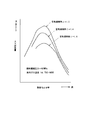
しかし、図5に示したように、スス排出量は酸素モル分率に対して上に凸となるような特性があることが確認された。また、同一の酸素モル分率であっても、空気過剰率が高くなるほど、スス排出量が減少される傾向があることが確認された。 However, as shown in FIG. 5, it was confirmed that the soot discharge amount has a characteristic that it protrudes upward with respect to the oxygen mole fraction. Further, it was confirmed that the soot discharge tends to decrease as the excess air ratio increases even at the same oxygen mole fraction.
また、図6に示すように、EGR率が低い場合には、圧縮上死点ガス温度(燃焼室内平均ガス温度)を上げてゆくとスス排出量が減少する温度領域があることが確認された。 Further, as shown in FIG. 6, it was confirmed that when the EGR rate is low, there is a temperature region in which the soot discharge amount decreases as the compression top dead center gas temperature (combustion chamber average gas temperature) is increased. .
更に、図7に示すように、空気過剰率1.4のときに、酸素モル分率に対してスス排出量が単調増加する傾向にあるような酸素モル分率の範囲においては、空気過剰率2.0、圧縮上死点ガス温度1100Kにすることにより、酸素モル分率に対してスス排出量が漸減するような傾向がみられる。 Further, as shown in FIG. 7, when the excess air ratio is 1.4, the excess air ratio is within the range of the oxygen mole fraction where the soot emission tends to monotonously increase with respect to the oxygen mole fraction. By setting the compression top dead center gas temperature to 2.0 and 1100 K, the soot discharge tends to gradually decrease with respect to the oxygen mole fraction.
従って、EGRシステムを備えEGRを実行する内燃機関においては、運転状態(回転速度、負荷、機関温度など)に応じて、例えば、目標性能(出力性能、燃費性能、排気性能(NOx排出量、スス排出量、パーティキュレート排出量)など)を達成することができる目標酸素モル分率を定め、その目標酸素モル分率を達成するように、空気過剰率、EGR率、残留ガス率などを制御することが、目標性能を効果的に達成するうえで有効である。 Therefore, in an internal combustion engine equipped with an EGR system and executing EGR, for example, target performance (output performance, fuel consumption performance, exhaust performance (NOx emissions, soot), etc., depending on operating conditions (rotation speed, load, engine temperature, etc.). The target oxygen mole fraction that can achieve the target emissions molar fraction is controlled, and the excess air ratio, EGR ratio, residual gas ratio, etc. are controlled to achieve the target oxygen mole fraction. Is effective in effectively achieving the target performance.
このため、本実施の形態では、内燃機関の性能実験等を行って、運転状態(内燃機関の回転速度、負荷、機関温度など)に応じて、目標性能(出力性能、燃費性能、排気性能(NOx排出量、スス排出量、パーティキュレート排出量)など)を達成することができる目標酸素モル分率を取得して、運転状態に応じた目標酸素モル分率の設定マップ等を作成し、これを記憶しておいて、実際の酸素モル分率が目標酸素モル分率となるような制御を行う。 For this reason, in the present embodiment, a performance experiment or the like of the internal combustion engine is performed, and the target performance (output performance, fuel consumption performance, exhaust performance (in accordance with the rotational speed of the internal combustion engine, load, engine temperature, etc.)) ( NOx emissions, soot emissions, particulate emissions, etc.) are obtained, and a target oxygen mole fraction setting map according to the operating state is created. Is stored, and control is performed so that the actual oxygen mole fraction becomes the target oxygen mole fraction.
このため、本実施の形態では、後述するが、内燃機関の実際の酸素モル分率を取得するため、酸素濃度を取得することができる酸素濃度センサを、例えば排気通路に配設する。なお、EGRガスが合流した後の吸気通路に酸素濃度センサを配設する構成とすることもできる。 For this reason, in this embodiment, as will be described later, an oxygen concentration sensor capable of acquiring the oxygen concentration is provided, for example, in the exhaust passage in order to acquire the actual oxygen mole fraction of the internal combustion engine. Note that an oxygen concentration sensor may be provided in the intake passage after the EGR gas has merged.
更に、本実施の形態に係る内燃機関においては、目標モル分率を実現するために、同一運転状態(内燃機関の回転速度や負荷など)において吸気充填効率(空気過剰率)、残留ガス率、EGR率を可変制御可能に構成されている。例えば、吸気充填効率(空気過剰率)、残留ガス率については後述するVVA機構により、EGR率についてはEGRシステムにより制御することができる。 Furthermore, in the internal combustion engine according to the present embodiment, in order to achieve the target molar fraction, the intake charge efficiency (excess air ratio), residual gas ratio, The EGR rate can be variably controlled. For example, the intake charge efficiency (excess air ratio) and the residual gas ratio can be controlled by a VVA mechanism which will be described later, and the EGR ratio can be controlled by an EGR system.
より具体的には、本実施の形態に係る内燃機関1には、図1に示すように、図示しないエアクリーナ等を介して外気(新気)が吸入されるが、該新気は吸気通路2を介して過給機3のコンプレッサ(インペラ)3Aに導かれて所定に圧縮された後、吸気通路2に介装されるインタークーラ4を介して所定に冷却されて、燃焼室(シリンダ)5内に導かれるようになっている。
More specifically, as shown in FIG. 1, outside air (fresh air) is sucked into the internal combustion engine 1 according to the present embodiment through an air cleaner or the like (not shown). After being guided to a compressor (impeller) 3A of the supercharger 3 through a compressor and compressed to a predetermined level, it is cooled to a predetermined level via an intercooler 4 interposed in the
そして、燃焼室5から排出される燃焼後のガスは、燃焼室5に臨んで開口される排気ポート(図示せず)を介して排気通路(排気マニホールド部分)6に導かれ、その後、過給機3の排気タービン3Bに回転エネルギを供給した後、排気通路6の下流に配設されている図示しない排気処理装置(酸化触媒、NOx低減触媒、ディーゼルパティキュレートフィルタなど)において所定の処理を受けて浄化され、大気中に排出される。
Then, the gas after combustion discharged from the
また、本実施の形態では、燃焼後のガス(すなわち、排気)の一部を吸気(新気)と共に燃焼室5に再び導くことで、燃焼温度を低下させてNOxの低減を図るためのEGR装置100が設けられている。
Further, in the present embodiment, part of the gas after combustion (that is, exhaust gas) is led again to the
本実施の形態に係るEGR装置(システム)100は、例えば、排気通路(排気マニホールド部分)6に連通されるEGR通路(排気還流通路)101を含んで構成され、該EGR通路101には当該EGR通路101を流れる排気(EGRガス:還流排気)を所定に冷却するためのEGRクーラ110が介装されている。
The EGR device (system) 100 according to the present embodiment includes, for example, an EGR passage (exhaust gas recirculation passage) 101 that communicates with an exhaust passage (exhaust manifold portion) 6, and the
EGR通路101と、吸気通路2と、の接続部付近には、EGRバルブ120が介装され、所定の運転状態において、所定に開弁されて、排気通路6を流れる排気の一部をEGRガスとして、EGRクーラ110により冷却しつつ、内燃機関1の吸気通路2に導くようになっている。
An
なお、EGR率の制御については、例えば、内燃機関の性能実験等を行って、運転状態(内燃機関の回転速度、負荷、機関温度など)に応じて、目標NOx排出量などを達成することができる目標EGR率が予め取得され、これに従って、EGR装置100のEGRバルブ120の開度が制御されるようになっている。
As for the control of the EGR rate, for example, a performance experiment of the internal combustion engine or the like is performed, and the target NOx emission amount or the like is achieved according to the operating state (rotational speed, load, engine temperature, etc. of the internal combustion engine). A target EGR rate that can be obtained is acquired in advance, and the opening degree of the
更に、本実施の形態に係る内燃機関1には、燃焼室5に臨んで設けられる吸気弁(及び/或いは排気弁)を駆動する動弁機構にはVVA(Variable Valve Actuation)機構200が備えられ、吸気弁(及び/或いは排気弁)の開閉タイミングやリフト量などの開閉特性を可変に制御することができるように構成されている。
Furthermore, the internal combustion engine 1 according to the present embodiment is provided with a VVA (Variable Valve Actuation)
なお、VVA機構200によれば、例えば、吸気弁(及び/或いは排気弁)の開閉タイミングやリフト量などを、筒内負圧の発生状態や吸気脈動などに応じて制御することで、低速から高速、更には軽負荷から高負荷まで広範囲な運転領域において吸気充填効率を効果的に増加させることが可能である。
Note that, according to the
このような構成を備えた内燃機関1において、本実施の形態では、運転状態(負荷や回転速度や機関温度など)に応じて設定されている目標酸素モル分率を達成するために、内燃機関1の燃焼室5に導入される吸気(新気+EGRガス)の実際の酸素モル分率を算出(取得)するための基本情報として、内燃機関1の燃焼室5に導入される吸気(新気+EGRガス)の酸素濃度を取得するが、そのために検出データが利用される酸素濃度センサ300が、排気通路に配設されている。
In the internal combustion engine 1 having such a configuration, in the present embodiment, in order to achieve the target oxygen mole fraction set according to the operating state (load, rotation speed, engine temperature, etc.), the internal combustion engine As basic information for calculating (acquiring) the actual oxygen mole fraction of intake air (new air + EGR gas) introduced into one
なお、本実施の形態では、酸素濃度センサ300の入手容易性や耐久性などの観点から排気通路に配設した場合を例示しているが、これに限定されるものではなく、EGRガスが合流した後の吸気通路2に酸素濃度センサ300を配設するような構成とすることもできる。
In the present embodiment, the case where the
そして、内燃機関1を制御するECU(図示せず)では、水温センサからの信号に基づいて冷却水温(機関温度)を取得し、クランク角センサなどからの信号に基づいてエンジン回転速度を取得すると共に、必要に応じてクランク角度位置などを取得することができるようになっている。 An ECU (not shown) that controls the internal combustion engine 1 acquires a cooling water temperature (engine temperature) based on a signal from a water temperature sensor, and acquires an engine rotation speed based on a signal from a crank angle sensor or the like. At the same time, the crank angle position and the like can be acquired as necessary.
また、ECUには、運転者のアクセルペダルの操作量(加速要求度合い)が入力され、ECUでは運転者の加速要求度合いに基づいて内燃機関1の燃料噴射供給量を設定すると共に、実際の燃料噴射弁の開弁信号などに基づいて内燃機関1の実際の負荷情報などを取得できるようになっている。 In addition, the operation amount (acceleration request level) of the driver's accelerator pedal is input to the ECU, and the ECU sets the fuel injection supply amount of the internal combustion engine 1 based on the driver's acceleration request level and the actual fuel. The actual load information of the internal combustion engine 1 can be acquired based on the valve opening signal of the injection valve.
更に、ECUには、VVA機構200によるバルブ開閉特性を制御するために必要な情報として、カム角センサなどからの信号が入力されている。
Further, a signal from a cam angle sensor or the like is input to the ECU as information necessary for controlling the valve opening / closing characteristics of the
このような構成を有する本実施の形態に係る内燃機関1においては、以下のような制御が行われる。
すなわち、図2に示すように、内燃機関1においては、比較的軽負荷(light load)な運転状態からアクセルペダルを踏み込んで比較的高負荷(heavy load)な運転状態へ移行する場合(登坂開始時など)、従来のように回転速度と燃料噴射量(燃料投入量)により内燃機関1の制御を行う場合、運転状態の変化度合い(過渡特性)に実際の制御が良好に追従することができず、酸素が不足した燃焼状態となり易く、スス排出量が増加するおそれがあった。
In the internal combustion engine 1 according to the present embodiment having such a configuration, the following control is performed.
That is, as shown in FIG. 2, in the internal combustion engine 1, when the accelerator pedal is depressed from a relatively light load operation state to a relatively high load operation state (uphill starting) When the internal combustion engine 1 is controlled by the rotational speed and the fuel injection amount (fuel injection amount) as in the past, the actual control can follow the change degree (transient characteristics) of the operating state well. Therefore, it is easy to become a combustion state in which oxygen is insufficient, and there is a possibility that the amount of soot emission increases.
逆に、比較的高負荷な運転状態からアクセルペダルの踏み代を少なくして比較的軽負荷な運転状態へ移行する場合(登坂終了時など)、従来のように回転速度と燃料噴射量(燃料投入量)により内燃機関1の制御を行う場合、運転状態の変化度合い(過渡特性)に実際の制御が良好に追従することができず、酸素が多い燃焼状態となり易く、NOx排出量が増加するおそれがあった。 Conversely, when shifting from a relatively high load operation state to a relatively light load operation state with a reduced accelerator pedal stroke (such as when climbing is completed), the rotational speed and fuel injection amount (fuel) When the internal combustion engine 1 is controlled by the input amount), the actual control cannot satisfactorily follow the degree of change in the operating state (transient characteristics), and the combustion state with a lot of oxygen tends to occur, and the NOx emission amount increases. There was a fear.
本実施の形態では、ECUが、酸素センサ300の検出結果などに基づいて、実際の酸素モル分率を取得して、目標酸素モル濃度となるように、VVA機構200を制御するようになっている。
In the present embodiment, the ECU acquires the actual oxygen mole fraction based on the detection result of the
図2の下段に示したように、ECUでは、筒内負圧の発生状態や吸気脈動などを利用して最大に吸気充填効率を増やすことができるポイントAと、全負荷におけるPmax(最大筒内圧力)が所定以上とならないためのポイントCと、の間で、目標酸素モル分率を達成可能な吸気弁の開時期Bを設定する。なお、ポイントAとポイントCが同一時期となる場合は、ポイントCを吸気弁の開弁時期Bとする。 As shown in the lower part of FIG. 2, the ECU uses a point A where the in-cylinder negative pressure is generated and intake pulsation, etc., to maximize the intake charge efficiency and Pmax (maximum in-cylinder) at full load. The intake valve opening timing B capable of achieving the target oxygen mole fraction is set between the point C for preventing the pressure) from exceeding a predetermined level. In addition, when the point A and the point C become the same time, the point C is set as the valve opening time B of the intake valve.
これにより、過渡運転時(上記の場合に限らず、負荷は変化せず回転速度が変化する場合や、回転速度は変化せず負荷が変化するような場合も含む)において、実際の酸素モル分率を取得し、目標酸素モル分率を達成することができるように、VVA機構200を制御するようにしたので、過渡運転時におけるNOx排出量の増大やスス排出量の悪化を抑制することができる。
Thus, during transient operation (not limited to the above case, including the case where the load does not change and the rotational speed changes, and the case where the rotational speed does not change and the load changes), the actual oxygen mole fraction Since the
従って、本実施の形態によれば、内燃機関1に既に備わっているシステムを有効に活用するものであるため、構成の複雑化やコストの増大などを招くことなく、燃焼改善を図ることができ、以って出力性能、燃費性能、排気性能などの各種の性能の改善を促進することができ、延いては後処理システムへの負担を軽減することができる内燃機関を提供することができる。 Therefore, according to the present embodiment, since the system already provided in the internal combustion engine 1 is effectively used, combustion improvement can be achieved without causing a complicated configuration and an increase in cost. Accordingly, it is possible to provide an internal combustion engine that can promote improvement in various performances such as output performance, fuel consumption performance, exhaust performance, and, in turn, can reduce the burden on the aftertreatment system.
なお、酸素モル分率を制御する手法としては、上述したような吸気弁の開閉特性を制御して吸気充填効率(空気過剰率)を制御することによる手法に限定されるものではなく、例えばVVA機構200により排気弁の開閉特性などを制御することによって残留ガス率を制御して酸素モル分率を所望に制御することも可能である。
The technique for controlling the oxygen mole fraction is not limited to the technique by controlling the intake valve opening / closing characteristics as described above to control the intake charge efficiency (excess air ratio), for example, VVA. It is also possible to control the oxygen mole fraction as desired by controlling the residual gas ratio by controlling the opening / closing characteristics of the exhaust valve by the
また、例えばEGR装置(システム)100のEGRバルブ120の開度を制御することで(目標EGR率に対応した目標開度に対して増減補正を施すなどして)、EGR率を制御して酸素モル分率を所望に制御することも可能である。
Further, for example, by controlling the opening degree of the
更に、本実施の形態に係る内燃機関1においては、図3に示すように、燃焼室5内に吸気を導く吸気ポートを、各気筒に2つずつ配設した構成を採用することができる。
Furthermore, in the internal combustion engine 1 according to the present embodiment, as shown in FIG. 3, it is possible to employ a configuration in which two intake ports for introducing intake air into the
2つの吸気ポートのうち、ダイレクショナルポート211は、比較的直線的な吸気通路により形成されており、燃焼室5の下方に向けて直線的で直接的に吸気を通気抵抗の小さい状態で導入させることができるようにシリンダヘッドに形成されている。
Of the two intake ports, the
この一方、ヘリカルポート212は、図3平面に略直交する方向から見て所定に曲がって形成され、燃焼室5の周方向への旋回成分(スワール成分)を与えながら吸気を導入させることができるようにシリンダヘッドに形成されている。
On the other hand, the
例えば、酸素モル分率が小さい場合(eol=((e+r)/(1+r))/λが大きい場合)には、スス排出量が多くなる傾向にあるため、そのような場合には、ヘリカルポート212側の吸気弁のリフト量を大きくするなどして、スワール比を上げて、スス排出量の低減を図るように制御する。 For example, when the oxygen mole fraction is small (eol = ((e + r) / (1 + r)) / λ is large), the soot discharge tends to increase. In such a case, the helical port Control is performed to increase the swirl ratio by increasing the lift amount of the intake valve on the 212 side and reduce the soot discharge amount.
一方、酸素モル分率が大きい場合(eol=((e+r)/(1+r))/λが小さい場合)にはスス排出量が低くなる傾向となるため、そのような場合には(スス排出量が少ないような場合)、ダイレクショナルポート211側の吸気弁のリフト量を大きくするなどして、スワール比を抑えて、NOx排出量を低減するような制御を行う。
On the other hand, when the oxygen mole fraction is large (eol = ((e + r) / (1 + r)) / λ is small), the soot discharge tends to be low. In such a case (soot discharge) In the case where there is a small amount), control is performed such that the swirl ratio is suppressed and the NOx emission amount is reduced by increasing the lift amount of the intake valve on the
また、図4に示すように、吸気弁のリフトを2段階で制御する場合には、低リフトから高リフトへ移るまでの時間を、それぞれのポート毎に制御するように構成することができる。 Further, as shown in FIG. 4, when the lift of the intake valve is controlled in two stages, it is possible to configure the time until the shift from the low lift to the high lift is controlled for each port.
なお、ヘリカルポート212側の吸気弁より先に、ダイレクショナルポート211側の吸気弁を高リフトへ移行させることで、筒内負圧が正圧に近づくため、ヘリカルポート212側から流入する空気量が減るため、スワール比を小さくすることができる。
Since the in-cylinder negative pressure approaches positive pressure by shifting the intake valve on the
逆に、ダイレクショナルポート211側の吸気弁より先に、ヘリカルポート212側の吸気弁を高リフトへ移行させることで、筒内負圧が大きい状態でヘリカルポート212側から空気を流入させることができるため、スワール比を大きくすることができる。
Conversely, the intake valve on the
このように、本実施の形態によれば、酸素モル分率に応じて、スワール比を制御するようにしたので、より一層、内燃機関の出力性能、燃費性能、排気性能などの改善に貢献することができる。 As described above, according to the present embodiment, the swirl ratio is controlled in accordance with the oxygen mole fraction, which further contributes to improvements in output performance, fuel consumption performance, exhaust performance, and the like of the internal combustion engine. be able to.
更に、ディーゼル燃焼を行う内燃機関1では、軽負荷領域(燃料噴射量が少ない運転領域)においては、燃料噴射量が少なく噴霧運動量が小さくなるため、燃料噴霧の周囲の雰囲気を燃焼している部分に良好に取り込むことができないため、あまり良好な燃焼を行うことができない。 Further, in the internal combustion engine 1 that performs diesel combustion, in the light load region (operation region where the fuel injection amount is small), the fuel injection amount is small and the spray momentum is small. Therefore, it is not possible to perform good combustion.
このような軽負荷運転領域では、例えば、VVA機構200を利用して、筒内へ導入される吸気(新気(外気)+EGRガス)量をできるだけ多くすることで筒内密度を増加させ、それによって燃焼改善を図ってスス排出量を低減することが可能である。
In such a light load operation region, for example, by using the
また、このような軽負荷領域において、スワール比を上げることができれば、噴霧運動量の不足を補って、燃料噴霧の周囲の雰囲気を燃焼している部分に良好に取り込ませることが可能となり、燃焼の改善を図ることができスス排出量を低減することができる。 In addition, if the swirl ratio can be increased in such a light load region, the shortage of the spray momentum can be compensated, and the atmosphere around the fuel spray can be well taken into the burning part, and the combustion can be reduced. Improvements can be made and soot emissions can be reduced.
このため、本実施の形態に係る内燃機関1では、軽負荷領域においては、スワール比を上げるように、VVA機構200を制御する。
For this reason, in the internal combustion engine 1 according to the present embodiment, the
スワール比を大きくするためには、上述したと同様に、ダイレクショナルポート211側の吸気弁のリフト量よりヘリカルポート212側の吸気弁のリフト量を上げたり、2段リフトの場合には先にヘリカルポート212側の吸気弁を高リフトへ移行させるようにすることで達成することができる。
In order to increase the swirl ratio, in the same way as described above, the lift amount of the intake valve on the
ところで、軽負荷領域は空気過剰率が大きいので酸素モル分率は大きな値となる一方、高負荷領域では空気過剰率が小さくなるので酸素モル分率は小さな値となる傾向にあるため、酸素モル分率に応じて、スワール比を制御することによって、内燃機関の出力性能、燃費性能、排気性能などの改善に貢献することができることになる。 By the way, since the excess air ratio is large in the light load region, the oxygen mole fraction has a large value, whereas in the high load region, the excess oxygen ratio becomes small, so the oxygen mole fraction tends to be small. By controlling the swirl ratio according to the fraction, it is possible to contribute to improvements in the output performance, fuel consumption performance, exhaust performance, etc. of the internal combustion engine.
例えば、酸素モル分率が大きな領域(軽負荷領域)では、スワール比を大きくして、燃焼の改善を図ってスス排出量を低減するような制御を行う一方で、酸素モル分率が小さな領域(高負荷領域)では、スワール比を小さくして、例えばダイレクショナルポート211を主に利用することで通気抵抗減による吸気量(充填効率)の増加を図ったり、オーバースワール等による噴霧干渉を抑制するような制御を行うことができる。
For example, in a region where the oxygen mole fraction is large (light load region), control is performed to increase the swirl ratio to improve combustion and reduce soot emissions, while the oxygen mole fraction is small. In (high load area), the swirl ratio is reduced, for example, the
このように、本実施の形態によれば、運転状態(負荷や回転速度など)に応じて設定される酸素モル分率に応じてスワール比を制御するようにしたので、より一層、内燃機関の出力性能、燃費性能、排気性能などの改善に貢献することができる。 As described above, according to the present embodiment, the swirl ratio is controlled according to the oxygen mole fraction set according to the operating state (load, rotation speed, etc.). This can contribute to improvements in output performance, fuel consumption performance, exhaust performance, etc.
ところで、本発明に係る内燃機関としては、ディーゼルエンジンが適用可能であるが、これに限定されるものではなく、アルコールその他の物質を燃料としてディーゼル燃焼を行う燃焼機関に適用することができ、移動式・定置式の何れに限定されるものではない。 By the way, as an internal combustion engine according to the present invention, a diesel engine is applicable, but is not limited to this, and can be applied to a combustion engine that performs diesel combustion using alcohol or other substances as a fuel. It is not limited to either a formula or a stationary formula.
また、VVA機構200は、特に限定されるものではなく、アクチュエータにより弁を駆動するような機構の他、カムを切り替えたり、カムを相対移動させたりするタイプの可変バルブ制御機構を採用することもできる。
The
更に、スワール比の制御は、VVA機構200による吸気弁の駆動制御によるものに限定されるものではなく、例えばバタフライバルブによってヘリカルポート212への吸気の流入を制御するようなスワール制御システムを利用することも可能である。
Furthermore, the control of the swirl ratio is not limited to that by the drive control of the intake valve by the
また、本発明は、排気タービン式過給機(ターボチャージャ)を備えた内燃機関に限定されるものではなく、他の排気を利用した過給機(プレッシャーウェーブ式など)や機械的に駆動されるスーパーチャージャーなどにも適用可能であるし、このような過給機を備えない所謂自然吸気式の内燃機関にも適用可能である。 Further, the present invention is not limited to an internal combustion engine having an exhaust turbine supercharger (turbocharger), but may be a turbocharger (such as a pressure wave type) using other exhaust or mechanically driven. The present invention can be applied to a supercharger or the like, or to a so-called naturally aspirated internal combustion engine that does not include such a supercharger.
更に、排気通路には、触媒装置やパティキュレートフィルタなどの後処理システムを介装することもできる。 Further, an aftertreatment system such as a catalyst device or a particulate filter can be interposed in the exhaust passage.
以上で説明した実施の形態は、本発明を説明するための例示に過ぎず、本発明の要旨を逸脱しない範囲内において、種々変更を加え得ることは可能である。 The embodiment described above is merely an example for explaining the present invention, and various modifications can be made without departing from the gist of the present invention.
1 内燃機関
2 吸気通路
3 排気過給機(ターボチャージャ)
5 燃焼室(シリンダ、筒内)
100 EGR装置
120 EGRバルブ
200 VVA機構(可変バルブ機構に相当)
211 ダイレクショナルポート
212 ヘリカルポート
300 酸素濃度センサ
1
5 Combustion chamber (cylinder, in cylinder)
100
211
Claims (3)
3. The internal combustion engine according to claim 1, wherein the excess air ratio is controlled by changing the intake charging efficiency by controlling the valve opening / closing characteristics by a variable valve mechanism.
Priority Applications (1)
| Application Number | Priority Date | Filing Date | Title |
|---|---|---|---|
| JP2010259051A JP5765921B2 (en) | 2010-11-19 | 2010-11-19 | Internal combustion engine |
Applications Claiming Priority (1)
| Application Number | Priority Date | Filing Date | Title |
|---|---|---|---|
| JP2010259051A JP5765921B2 (en) | 2010-11-19 | 2010-11-19 | Internal combustion engine |
Publications (2)
| Publication Number | Publication Date |
|---|---|
| JP2012107601A true JP2012107601A (en) | 2012-06-07 |
| JP5765921B2 JP5765921B2 (en) | 2015-08-19 |
Family
ID=46493460
Family Applications (1)
| Application Number | Title | Priority Date | Filing Date |
|---|---|---|---|
| JP2010259051A Active JP5765921B2 (en) | 2010-11-19 | 2010-11-19 | Internal combustion engine |
Country Status (1)
| Country | Link |
|---|---|
| JP (1) | JP5765921B2 (en) |
Cited By (3)
| Publication number | Priority date | Publication date | Assignee | Title |
|---|---|---|---|---|
| JP2015058924A (en) * | 2013-09-20 | 2015-03-30 | いすゞ自動車株式会社 | Hybrid system, hybrid vehicle and method of controlling hybrid system |
| JP2016003589A (en) * | 2014-06-16 | 2016-01-12 | スズキ株式会社 | Combustion timing estimation device and combustion timing estimation method for homogeneous charge compression self-ignition internal combustion engine |
| JP2017082799A (en) * | 2016-12-16 | 2017-05-18 | スズキ株式会社 | Control device for pre-mixing compression self-ignition type internal combustion engine |
Citations (12)
| Publication number | Priority date | Publication date | Assignee | Title |
|---|---|---|---|---|
| JPH01125555A (en) * | 1987-11-09 | 1989-05-18 | Kunio Terao | Method for driving spark ignition engine |
| JPH09126060A (en) * | 1995-11-08 | 1997-05-13 | Isuzu Motors Ltd | Method and device for controlling exhaust gas reflux |
| JPH1037786A (en) * | 1996-07-19 | 1998-02-10 | Nippon Soken Inc | Control device of diesel engine |
| JP2000274286A (en) * | 1999-03-19 | 2000-10-03 | Nissan Motor Co Ltd | Direct injection type diesel engine |
| JP2002227705A (en) * | 2001-01-30 | 2002-08-14 | Nissan Motor Co Ltd | Control device for diesel engine |
| JP2004332658A (en) * | 2003-05-09 | 2004-11-25 | Nissan Motor Co Ltd | Ignition timing control device for internal combustion engine |
| JP2006083735A (en) * | 2004-09-15 | 2006-03-30 | Toyota Motor Corp | Control device for internal combustion engine |
| JP2006249972A (en) * | 2005-03-09 | 2006-09-21 | Toyota Motor Corp | Fuel injection controller for internal combustion engine |
| JP2006274977A (en) * | 2005-03-30 | 2006-10-12 | Nissan Motor Co Ltd | Control device for internal combustion engine |
| JP2006312933A (en) * | 2005-05-03 | 2006-11-16 | Crf Scpa | Method for controlling air intake flow of internal combustion engine |
| US20100024787A1 (en) * | 2008-08-01 | 2010-02-04 | Chi John N | Apparatus, system, and method for controlling exhaust emissions using a pre-filter |
| JP2010121606A (en) * | 2008-11-21 | 2010-06-03 | Mitsubishi Fuso Truck & Bus Corp | Optimization method for engine control parameter |
-
2010
- 2010-11-19 JP JP2010259051A patent/JP5765921B2/en active Active
Patent Citations (12)
| Publication number | Priority date | Publication date | Assignee | Title |
|---|---|---|---|---|
| JPH01125555A (en) * | 1987-11-09 | 1989-05-18 | Kunio Terao | Method for driving spark ignition engine |
| JPH09126060A (en) * | 1995-11-08 | 1997-05-13 | Isuzu Motors Ltd | Method and device for controlling exhaust gas reflux |
| JPH1037786A (en) * | 1996-07-19 | 1998-02-10 | Nippon Soken Inc | Control device of diesel engine |
| JP2000274286A (en) * | 1999-03-19 | 2000-10-03 | Nissan Motor Co Ltd | Direct injection type diesel engine |
| JP2002227705A (en) * | 2001-01-30 | 2002-08-14 | Nissan Motor Co Ltd | Control device for diesel engine |
| JP2004332658A (en) * | 2003-05-09 | 2004-11-25 | Nissan Motor Co Ltd | Ignition timing control device for internal combustion engine |
| JP2006083735A (en) * | 2004-09-15 | 2006-03-30 | Toyota Motor Corp | Control device for internal combustion engine |
| JP2006249972A (en) * | 2005-03-09 | 2006-09-21 | Toyota Motor Corp | Fuel injection controller for internal combustion engine |
| JP2006274977A (en) * | 2005-03-30 | 2006-10-12 | Nissan Motor Co Ltd | Control device for internal combustion engine |
| JP2006312933A (en) * | 2005-05-03 | 2006-11-16 | Crf Scpa | Method for controlling air intake flow of internal combustion engine |
| US20100024787A1 (en) * | 2008-08-01 | 2010-02-04 | Chi John N | Apparatus, system, and method for controlling exhaust emissions using a pre-filter |
| JP2010121606A (en) * | 2008-11-21 | 2010-06-03 | Mitsubishi Fuso Truck & Bus Corp | Optimization method for engine control parameter |
Cited By (3)
| Publication number | Priority date | Publication date | Assignee | Title |
|---|---|---|---|---|
| JP2015058924A (en) * | 2013-09-20 | 2015-03-30 | いすゞ自動車株式会社 | Hybrid system, hybrid vehicle and method of controlling hybrid system |
| JP2016003589A (en) * | 2014-06-16 | 2016-01-12 | スズキ株式会社 | Combustion timing estimation device and combustion timing estimation method for homogeneous charge compression self-ignition internal combustion engine |
| JP2017082799A (en) * | 2016-12-16 | 2017-05-18 | スズキ株式会社 | Control device for pre-mixing compression self-ignition type internal combustion engine |
Also Published As
| Publication number | Publication date |
|---|---|
| JP5765921B2 (en) | 2015-08-19 |
Similar Documents
| Publication | Publication Date | Title |
|---|---|---|
| US10570808B2 (en) | Method and system for controlling engine | |
| JP4780059B2 (en) | Control device for internal combustion engine | |
| JP2010096049A (en) | Control device of internal combustion engine | |
| JP5403277B2 (en) | Internal combustion engine | |
| JP2009216059A (en) | Control device for internal combustion engine | |
| JP5765921B2 (en) | Internal combustion engine | |
| JP2009002275A (en) | Control system of internal combustion engine | |
| JP6001497B2 (en) | Intake device for internal combustion engine | |
| JP4591403B2 (en) | Control device for internal combustion engine | |
| EP2706218B1 (en) | Internal combustion engine operation control method | |
| JP2010209683A (en) | Control device for internal combustion engine | |
| JP4114008B2 (en) | Control device for spark ignition direct injection engine with turbocharger | |
| JP2002364412A (en) | Exhaust emission control device for engine with turbo supercharger | |
| JP5689830B2 (en) | Internal combustion engine | |
| JP4258388B2 (en) | Internal combustion engine and operation control device for internal combustion engine | |
| JP6699272B2 (en) | Engine and control method thereof | |
| JP2008038622A (en) | Exhaust emission control device and method of internal combustion engine | |
| JP4404841B2 (en) | Control device for internal combustion engine | |
| JP6406158B2 (en) | Engine control device | |
| JP5983285B2 (en) | Turbocharged engine | |
| KR101226058B1 (en) | Valve Operation Control Method for Preventing the Carbon Deposition of Spark Plug in a Direct Injection Gasoline Engine | |
| JP2007327379A (en) | Control device for internal combustion engine system | |
| JP6638499B2 (en) | Engine and engine control method | |
| JP4405275B2 (en) | Control device for internal combustion engine | |
| JP4278573B2 (en) | Exhaust gas purification device for internal combustion engine |
Legal Events
| Date | Code | Title | Description |
|---|---|---|---|
| A621 | Written request for application examination |
Free format text: JAPANESE INTERMEDIATE CODE: A621 Effective date: 20131018 |
|
| A977 | Report on retrieval |
Free format text: JAPANESE INTERMEDIATE CODE: A971007 Effective date: 20140422 |
|
| A131 | Notification of reasons for refusal |
Free format text: JAPANESE INTERMEDIATE CODE: A131 Effective date: 20140430 |
|
| A521 | Request for written amendment filed |
Free format text: JAPANESE INTERMEDIATE CODE: A523 Effective date: 20140626 |
|
| A131 | Notification of reasons for refusal |
Free format text: JAPANESE INTERMEDIATE CODE: A131 Effective date: 20141114 |
|
| A521 | Request for written amendment filed |
Free format text: JAPANESE INTERMEDIATE CODE: A523 Effective date: 20150109 |
|
| TRDD | Decision of grant or rejection written | ||
| A01 | Written decision to grant a patent or to grant a registration (utility model) |
Free format text: JAPANESE INTERMEDIATE CODE: A01 Effective date: 20150609 |
|
| A61 | First payment of annual fees (during grant procedure) |
Free format text: JAPANESE INTERMEDIATE CODE: A61 Effective date: 20150616 |
|
| R150 | Certificate of patent or registration of utility model |
Ref document number: 5765921 Country of ref document: JP Free format text: JAPANESE INTERMEDIATE CODE: R150 |
|
| R250 | Receipt of annual fees |
Free format text: JAPANESE INTERMEDIATE CODE: R250 |
|
| R250 | Receipt of annual fees |
Free format text: JAPANESE INTERMEDIATE CODE: R250 |
|
| R250 | Receipt of annual fees |
Free format text: JAPANESE INTERMEDIATE CODE: R250 |
|
| R250 | Receipt of annual fees |
Free format text: JAPANESE INTERMEDIATE CODE: R250 |