JP2012105977A - Apparatus and method for providing electric cable within magnetic resonance imaging system - Google Patents
Apparatus and method for providing electric cable within magnetic resonance imaging system Download PDFInfo
- Publication number
- JP2012105977A JP2012105977A JP2011242975A JP2011242975A JP2012105977A JP 2012105977 A JP2012105977 A JP 2012105977A JP 2011242975 A JP2011242975 A JP 2011242975A JP 2011242975 A JP2011242975 A JP 2011242975A JP 2012105977 A JP2012105977 A JP 2012105977A
- Authority
- JP
- Japan
- Prior art keywords
- cable
- support structure
- rigid support
- tube
- electrical
- Prior art date
- Legal status (The legal status is an assumption and is not a legal conclusion. Google has not performed a legal analysis and makes no representation as to the accuracy of the status listed.)
- Granted
Links
- 238000002595 magnetic resonance imaging Methods 0.000 title claims abstract description 54
- 238000000034 method Methods 0.000 title claims abstract description 21
- 230000008878 coupling Effects 0.000 claims abstract description 6
- 238000010168 coupling process Methods 0.000 claims abstract description 6
- 238000005859 coupling reaction Methods 0.000 claims abstract description 6
- 239000004593 Epoxy Substances 0.000 claims description 6
- 238000007906 compression Methods 0.000 claims description 4
- 230000006835 compression Effects 0.000 claims description 4
- 239000003365 glass fiber Substances 0.000 claims description 2
- 238000003384 imaging method Methods 0.000 description 32
- 238000012545 processing Methods 0.000 description 17
- 230000007246 mechanism Effects 0.000 description 16
- 239000000463 material Substances 0.000 description 11
- 238000002788 crimping Methods 0.000 description 7
- 238000004382 potting Methods 0.000 description 7
- 238000003860 storage Methods 0.000 description 7
- 238000010586 diagram Methods 0.000 description 6
- 230000014509 gene expression Effects 0.000 description 5
- 229910052734 helium Inorganic materials 0.000 description 5
- 239000001307 helium Substances 0.000 description 5
- SWQJXJOGLNCZEY-UHFFFAOYSA-N helium atom Chemical compound [He] SWQJXJOGLNCZEY-UHFFFAOYSA-N 0.000 description 5
- 230000008569 process Effects 0.000 description 5
- 238000002059 diagnostic imaging Methods 0.000 description 4
- 238000004891 communication Methods 0.000 description 3
- 238000002591 computed tomography Methods 0.000 description 3
- 238000004590 computer program Methods 0.000 description 3
- 230000007717 exclusion Effects 0.000 description 3
- 230000006870 function Effects 0.000 description 3
- 238000012986 modification Methods 0.000 description 3
- 230000004048 modification Effects 0.000 description 3
- 238000013480 data collection Methods 0.000 description 2
- 230000005284 excitation Effects 0.000 description 2
- 239000012212 insulator Substances 0.000 description 2
- 239000007788 liquid Substances 0.000 description 2
- 229910052751 metal Inorganic materials 0.000 description 2
- 239000002184 metal Substances 0.000 description 2
- 230000003287 optical effect Effects 0.000 description 2
- 230000003068 static effect Effects 0.000 description 2
- 238000004804 winding Methods 0.000 description 2
- 230000000712 assembly Effects 0.000 description 1
- 238000000429 assembly Methods 0.000 description 1
- 230000005540 biological transmission Effects 0.000 description 1
- 239000003518 caustics Substances 0.000 description 1
- 239000003795 chemical substances by application Substances 0.000 description 1
- 230000000295 complement effect Effects 0.000 description 1
- 238000001514 detection method Methods 0.000 description 1
- 230000005672 electromagnetic field Effects 0.000 description 1
- 239000000945 filler Substances 0.000 description 1
- 239000006260 foam Substances 0.000 description 1
- 238000003780 insertion Methods 0.000 description 1
- 230000037431 insertion Effects 0.000 description 1
- 238000002372 labelling Methods 0.000 description 1
- 238000004519 manufacturing process Methods 0.000 description 1
- 150000002739 metals Chemical class 0.000 description 1
- 229910052755 nonmetal Inorganic materials 0.000 description 1
- 150000002843 nonmetals Chemical class 0.000 description 1
- 238000001208 nuclear magnetic resonance pulse sequence Methods 0.000 description 1
- 238000009206 nuclear medicine Methods 0.000 description 1
- 230000002093 peripheral effect Effects 0.000 description 1
- 238000002600 positron emission tomography Methods 0.000 description 1
- 230000002787 reinforcement Effects 0.000 description 1
- 239000011347 resin Substances 0.000 description 1
- 229920005989 resin Polymers 0.000 description 1
- 239000004065 semiconductor Substances 0.000 description 1
- 230000008054 signal transmission Effects 0.000 description 1
- 238000002603 single-photon emission computed tomography Methods 0.000 description 1
- 125000006850 spacer group Chemical group 0.000 description 1
- 229910001220 stainless steel Inorganic materials 0.000 description 1
- 239000010935 stainless steel Substances 0.000 description 1
- 238000002604 ultrasonography Methods 0.000 description 1
- 230000000007 visual effect Effects 0.000 description 1
Images


Classifications
-
- G—PHYSICS
- G01—MEASURING; TESTING
- G01R—MEASURING ELECTRIC VARIABLES; MEASURING MAGNETIC VARIABLES
- G01R33/00—Arrangements or instruments for measuring magnetic variables
- G01R33/20—Arrangements or instruments for measuring magnetic variables involving magnetic resonance
- G01R33/28—Details of apparatus provided for in groups G01R33/44 - G01R33/64
- G01R33/32—Excitation or detection systems, e.g. using radio frequency signals
- G01R33/36—Electrical details, e.g. matching or coupling of the coil to the receiver
-
- G—PHYSICS
- G01—MEASURING; TESTING
- G01R—MEASURING ELECTRIC VARIABLES; MEASURING MAGNETIC VARIABLES
- G01R33/00—Arrangements or instruments for measuring magnetic variables
- G01R33/20—Arrangements or instruments for measuring magnetic variables involving magnetic resonance
- G01R33/28—Details of apparatus provided for in groups G01R33/44 - G01R33/64
- G01R33/38—Systems for generation, homogenisation or stabilisation of the main or gradient magnetic field
- G01R33/385—Systems for generation, homogenisation or stabilisation of the main or gradient magnetic field using gradient magnetic field coils
- G01R33/3858—Manufacture and installation of gradient coils, means for providing mechanical support to parts of the gradient-coil assembly
-
- Y—GENERAL TAGGING OF NEW TECHNOLOGICAL DEVELOPMENTS; GENERAL TAGGING OF CROSS-SECTIONAL TECHNOLOGIES SPANNING OVER SEVERAL SECTIONS OF THE IPC; TECHNICAL SUBJECTS COVERED BY FORMER USPC CROSS-REFERENCE ART COLLECTIONS [XRACs] AND DIGESTS
- Y10—TECHNICAL SUBJECTS COVERED BY FORMER USPC
- Y10T—TECHNICAL SUBJECTS COVERED BY FORMER US CLASSIFICATION
- Y10T29/00—Metal working
- Y10T29/49—Method of mechanical manufacture
- Y10T29/49002—Electrical device making
Landscapes
- Physics & Mathematics (AREA)
- Condensed Matter Physics & Semiconductors (AREA)
- General Physics & Mathematics (AREA)
- Magnetic Resonance Imaging Apparatus (AREA)
- Details Of Indoor Wiring (AREA)
Abstract
Description
本明細書に開示した主題は全般的には診断撮像システムに関し、またさらに詳細には磁気共鳴撮像(MRI)システム内部へのケーブル(特に、MRIシステム内部に電気接続を提供するケーブル)の装着に関する。 The subject matter disclosed herein relates generally to diagnostic imaging systems, and more particularly to mounting cables within a magnetic resonance imaging (MRI) system, particularly cables that provide electrical connections within the MRI system. .
MRIシステムは、時間的に一定の(すなわち、均一で静的な)主要磁場すなわち主磁場を発生させる超伝導マグネットを含むことが可能である。MRIデータ収集は、MRIシステムのガントリの内部を延びるケーブルを通して信号を受け取る磁場傾斜コイルを用いて主要磁場内部に磁気モーメントを励起させることによって達成される。例えばある関心領域を撮像するためには、磁場傾斜コイルを順次式にパルス動作させてMRIスキャナのボア内にパルス状の傾斜磁場を生成し、関心領域に対応したボリュームを選択的に励起させて関心領域のMR画像を収集している。作成により得られる画像は、関心領域の構造及び機能を示している。 The MRI system can include a superconducting magnet that generates a main magnetic field that is constant in time (ie, uniform and static). MRI data collection is accomplished by exciting a magnetic moment inside the main magnetic field using a magnetic field gradient coil that receives signals through cables extending inside the gantry of the MRI system. For example, in order to image a region of interest, a magnetic field gradient coil is sequentially pulsed to generate a pulsed gradient magnetic field in the bore of the MRI scanner, and a volume corresponding to the region of interest is selectively excited. MR images of the region of interest are collected. The image obtained by the creation shows the structure and function of the region of interest.
従来のMRIシステムでは、傾斜コイルに対する電気接続に関する装着機構は、傾斜コイルに信号を伝送するケーブルを適正に支持しなければならない。時変動する磁場を発生させるために傾斜コイルに(例えば、パルスシーケンスの一部として)印加される電流パルスは、傾斜コイルに動きや振動を生じさせるうず電流を誘導する可能性がある。適正な支持が設けられず、またコイルのパルス動作中の電磁気結合や振動などからの過剰な動きが生じると、得られた画像内に画像アーチファクト(例えば、画像内の白画素など)が生じる可能性がある。しかし、装着機構の剛性が過剰であると、傾斜コイル端子上に電磁気結合や振動に由来する応力がかかることになり、このためにケーブルや端子の破損を生じる可能性がある。 In conventional MRI systems, the mounting mechanism for electrical connection to the gradient coil must properly support the cable that transmits signals to the gradient coil. Current pulses applied to a gradient coil (eg, as part of a pulse sequence) to generate a time-varying magnetic field can induce eddy currents that cause movement and vibration in the gradient coil. If there is no proper support and excessive movement from electromagnetic coupling or vibration during coil pulse operation, image artifacts (eg white pixels in the image) may occur in the resulting image. There is sex. However, when the rigidity of the mounting mechanism is excessive, stress due to electromagnetic coupling or vibration is applied to the gradient coil terminal, which may cause damage to the cable and the terminal.
これらの問題点を解決しようと試みたブラケットやプレートなどの周知の方法や装着機構は、据付けが困難であり、重量が大きく、費用が高く、また歪み取りなどの追加的な構成要素を必要とすることがあり、このため別の問題(例えば、留め具の緩みなど)が生じる可能性がある。こうした周知の方法及び装着機構でも同様に、支持提供の不十分や支持提供の過剰に関連する問題のうちの幾つかが依然として難点となることがある。 Known methods and mounting mechanisms, such as brackets and plates that attempt to solve these problems, are difficult to install, are heavy, expensive, and require additional components such as distortion relief. This can cause other problems (eg, loose fasteners). As with these known methods and mounting mechanisms, some of the problems associated with poor support provision and excessive support provision may still be problematic.
一実施形態では、ある断面を有するチャンネルを画定する剛性の支持構造と、該チャンネルの断面と比べて断面がより小さい電気ケーブルと、を含む磁気共鳴撮像(MRI)システム向けのケーブルアセンブリを提供する。この電気ケーブルは、剛性の支持構造がその電気ケーブルを接続させる先の可動構成要素からの動きに抗するためにMRIシステムの静止構成要素に結合するように構成されるようにして剛性の支持構造のチャンネルの内部に確保されている。 In one embodiment, a cable assembly for a magnetic resonance imaging (MRI) system is provided that includes a rigid support structure defining a channel having a cross section and an electrical cable having a smaller cross section than the cross section of the channel. . The electrical cable is configured so that the rigid support structure is configured to couple to a stationary component of the MRI system to resist movement from a movable component to which the electrical cable is connected. Secured inside the channel.
別の実施形態では、MRIシステムのマグネットフランジと、チャンネルを画定すると共に該マグネットフランジと結合された剛性のチューブと、を含む磁気共鳴撮像(MRI)システム向けの電気接続機構を提供する。本電気接続機構はさらに、剛性のチューブの内部を延びると共にここに確保された電気ケーブルと電気端子とを含んでおり、該電気ケーブルの一方の端部は該電気端子に接続されている。 In another embodiment, an electrical connection mechanism for a magnetic resonance imaging (MRI) system is provided that includes a magnet flange of an MRI system and a rigid tube that defines a channel and is coupled to the magnet flange. The electrical connection mechanism further includes an electrical cable and an electrical terminal extending through the rigid tube and secured therein, and one end of the electrical cable is connected to the electrical terminal.
さらに別の実施形態では、磁気共鳴撮像(MRI)システム向けの支持付ケーブルを設けるための方法は、剛性のチューブの内部に電気ケーブルを挿入するステップと、該剛性のチューブの内部で電気ケーブルを確保しケーブルアセンブリを形成するステップと、を含む。本方法はさらに、電気ケーブルの一方の端部がMRIシステムの傾斜コイルの傾斜コイル端子に接続されるようにしてケーブルアセンブリをMRIシステムのマグネットフランジに結合させるステップを含む。 In yet another embodiment, a method for providing a supported cable for a magnetic resonance imaging (MRI) system includes inserting an electrical cable inside a rigid tube, and connecting the electrical cable inside the rigid tube. Securing and forming a cable assembly. The method further includes coupling the cable assembly to the magnetic flange of the MRI system such that one end of the electrical cable is connected to the gradient coil terminal of the gradient coil of the MRI system.
上述した要約並びにある種の実施形態に関する以下の詳細な説明は、添付の図面と共に読むことによってさらに十分な理解が得られよう。これらの図面が様々な実施形態の機能ブロックからなる図を表している場合も、必ずしもこれらの機能ブロックがハードウェア回路間で分割されることを意味するものではない。したがって例えば、1つまたは複数の機能ブロック(例えば、プロセッサやメモリ)を単一のハードウェア(例えば、汎用の信号プロセッサまたはランダムアクセスメモリ、ハードディスク、その他)の形で実現させることがある。同様にそのプログラムは、スタンドアロンのプログラムとすること、オペレーティングシステム内のサブルーチンとして組み込まれること、インストールしたソフトウェアパッケージの形で機能させること、その他とすることができる。こうした様々な実施形態は図面に示した配置や手段に限定されるものではないことを理解すべきである。 The foregoing summary, as well as the following detailed description of certain embodiments, will be better understood when read in conjunction with the appended drawings. Even when these drawings represent diagrams including functional blocks of various embodiments, it does not necessarily mean that these functional blocks are divided among hardware circuits. Thus, for example, one or more functional blocks (eg, processor or memory) may be implemented in the form of a single piece of hardware (eg, a general purpose signal processor or random access memory, a hard disk, etc.). Similarly, the program can be a stand-alone program, incorporated as a subroutine in the operating system, functioning in an installed software package, or the like. It should be understood that these various embodiments are not limited to the arrangements and instrumentality shown in the drawings.
本明細書で使用する場合、単数形で「a」や「an」の語を前に付けて記載した要素やステップは、これに関する複数の要素やステップも排除していない(こうした排除を明示的に記載している場合を除く)と理解すべきである。さらに、「一実施形態」に対する言及は、記載した特徴も組み込んでいる追加的な実施形態の存在を排除すると理解されるように意図したものではない。さらに特に明示的に否定する記述をしない限り、ある具体的な性状を有する1つまたは複数の構成要素を「備える(comprising)」または「有する(having)」実施形態は、当該性状を有しないこうした構成要素を追加的に含むことがある。 As used herein, an element or step prefixed with the words “a” or “an” does not exclude a plurality of elements or steps in this context (an explicit exclusion of such an exclusion). Should be understood). Furthermore, references to “one embodiment” are not intended to be interpreted as excluding the existence of additional embodiments that also incorporate the recited features. In addition, unless specifically stated to the contrary, embodiments that “comprise” or “have” one or more components that have a particular property are those that do not have that property. May contain additional components.
磁気共鳴撮像(MRI)システム内部において電気ケーブルなどの電気接続を支持し装着するための方法及び装置を提供する。例えば様々な実施形態は、傾斜コイル電気接続のための電気ケーブルの少なくとも一部分を囲繞している支持構造(例えば、チューブやチャンネル)を提供する。このケーブルは支持体内部において、例えばポッティングや圧着留めによることを含む様々な方法で維持されることがある。少なくとも1つの実施形態を実施することによって、MRIシステム内部での電気ケーブルの振動に対して、例えば傾斜コイルへの接続の箇所において抗すると共にここで振動を逃がしている。 Methods and apparatus are provided for supporting and mounting electrical connections, such as electrical cables, within a magnetic resonance imaging (MRI) system. For example, various embodiments provide a support structure (eg, a tube or channel) that surrounds at least a portion of an electrical cable for gradient coil electrical connection. This cable may be maintained within the support in a variety of ways, including, for example, by potting or crimping. By implementing at least one embodiment, the vibration of the electrical cable inside the MRI system is countered, for example, at the point of connection to the gradient coil, and here the vibration is released.
これらの様々な実施形態は電気ケーブルによる実現形態に限定されるものではなく、光ケーブル(ただし、これに限らない)などの別のケーブルによる接続にも使用し得ることに留意すべきである。さらに、様々な実施形態を電気接続が傾斜コイルに対して設けられるように記載することがあるが、MRIシステム内部の無線周波数(RF)コイルに対するなど別の接続を製作することもできる。 It should be noted that these various embodiments are not limited to electrical cable implementations, and may be used for connections with other cables such as, but not limited to, optical cables. Further, although various embodiments may be described such that electrical connections are provided to the gradient coils, other connections can be made, such as to radio frequency (RF) coils within the MRI system.
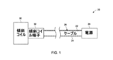
図1は、様々な実施形態に従って形成されたケーブル支持機構20の簡略ブロック図を表している。ケーブル支持機構20は、MRIシステム内部に剛性に装着されながらも例えば電磁気結合や振動により生じる力の吸収が可能である支持構造24によってケーブル22を支持し維持している。支持構造24は、ケーブル22の少なくとも一部分をその内部において支持することが可能な任意の構造(例えば、ケーブル22の一部または全部を囲繞するチューブやチャンネル)とすることが可能である。例えば支持構造24は、支持構造24内部でケーブル22を周回方向に取り囲んでギャップ26が設けられるようにケーブル22の断面と比べて若干大きな断面(例えば、直径)を有するチューブとすることがある。ギャップ26のサイズは、例えばケーブル22のサイズ、ケーブル22に加わると予測される力の量、その他に基づいて異ならせることがある。
FIG. 1 depicts a simplified block diagram of a
幾つかの実施形態ではそのケーブル22は、電源28(例えば、パルス発生源)とMRIシステム内部にある移動可能な構成要素などの1つまたは複数の構成要素との間に電気接続を提供する。例えばケーブル22は、MRIシステムの外部(または、MRIシステムのマグネットシステムの外部)にある電源28とMRIシステム内部にある1つまたは複数の構成要素との間に電気接続を提供する適当な任意の電気ケーブルまたはワイヤとすることができる。この1つまたは複数の構成要素は、電気端子(傾斜コイル端子32として図示)などの接続部材を介してケーブル22に接続された1つまたは複数の傾斜コイル30などMRIシステム内部にあって電力または信号を要求する任意の構成要素とすることがある。この接続部材は、MRIシステムに適した端子接続など適当な任意の接続部材とすることがある。この1つまたは複数の傾斜コイル30や付属の構成要素はその動作時に移動することがあり得ることに留意すべきである。
In some embodiments, the
ケーブル支持機構20は、MRIシステムの任意の部分(例えば、MRIシステムのガントリの内部の一部分を示した図2に示すようなマグネットフランジ40などの静止構成要素)にケーブル22を装着するのために利用されることがある。支持構造24はケーブル22の長さ全体を囲繞することもケーブル22の長さの一部を囲繞することもあることに留意すべきである。例えば、ケーブル22のうちコイル端子32に隣接した(例えば、1インチにある)部分として図示している傾斜コイル端子32を囲繞する端子領域42内において、ケーブル22は支持構造24から延び出ており支持構造24により囲繞されないことがある。したがってこの端子領域42においてケーブル22は、歪み取りのための柔軟性を可能とさせるように様々な実施形態では支持されていない。
The
図2から分かるように支持構造24は、ブラケットや適当な別の任意の装着デバイスとし得る複数の留め具44によってフランジ40に装着されている。ケーブル22は例証を目的として示したものであり、幾つかの実施形態では支持構造24により部分的に取り囲まれることも支持構造24にその全体が取り囲まれることもあり得ることに留意すべきである。留め具44は、ボルトやその他の適当なタイプの確保部材によってフランジ40に対して確保されることがある。支持要件、ケーブル22の長さ、ケーブル22内の周回数や曲げの数、その他に基づくなどして留め具44を図示した数より多く設けることも少なく設けることもあることに留意すべきである。留め具44は、フランジ40上の支持構造24の位置を確実に維持するように、様々な実施形態では支持構造24の少なくとも一部分がフランジ40と接触するようにして、支持構造24の外部に対して(例えば、フランジ40の端部平面に対して)確保している。しかし別の実施形態ではその支持構造24は、例えば留め具44の底部が高くなっている場合に、フランジ40からある間隔だけ離されることがある。
As can be seen in FIG. 2, the
留め具44は、支持構造24から離間させることや、その一部として形成させることがある。幾つかの実施形態ではその留め具44は、支持構造24の周縁部の少なくとも一部分をその内部に受け容れると共に支持構造24をフランジ40に対して確保するための湾曲部分を含む。
The
外部電源28(図1参照)と傾斜コイル30に電力を提供するケーブル22との間に接続を提供するインタフェース48などの別の留め具や構成要素が設けられることがあり得ることに留意すべきである。様々な実施形態では、ケーブル22と異なる追加のケーブル50(または、ワイヤ)によって電源28をインタフェース48に接続している。ケーブル50は支持構造24を含まないことがある。
It should be noted that other fasteners and components may be provided such as an
フランジ40は図示した実施形態では、その中を通過するボア46を有するマグネットフランジである。例えばフランジ40は、MRIシステムの超伝導マグネットを支持するマグネットコイル支持構造56(例えば、マグネット巻型)の各端部上に設けられることがある。内側支持構造54をフランジ40に装着しているブラケット52などのその他の構成要素が設けられることがある。さらにマグネットコイル支持構造56は、マグネットコイル支持構造56を垂直方向に維持するため、また任意選択ではフランジ40を床などの支持物に対して確保してその動きに抗するまたは動きを防止するための脚部58を含むことがある。
In the illustrated embodiment, the
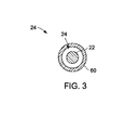
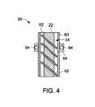
支持構造24に関しては様々な実施形態及び構成を提供することができ、ここでこれについて説明することにする。異なる実施形態について別々に図示し説明しているが、実施形態やその特徴のうちの1つまたは幾つかが組み合わされることもあり得ることに留意すべきである。さらに図示した実施形態に対して様々な構成や修正が企図されよう。図3及び4は、ケーブル22をその内部に受け容れるためにその中を通る通路またはチャンネルを有するチューブ60(例えば、剛性のコンジット)から形成させた支持構造24の一実施形態を表している。チューブ60は様々な実施形態では、ギャップ26を画定するようにケーブル22の断面と比べてより大きな断面を有する剛性の構造として形成されている。チューブ60は、例えばステンレス鋼などの金属からなど任意の剛性材料から形成されることがある。しかし、剛性特性を提供するようなその他の金属や非金属が用いられることもある。チューブ60の剛性は、チューブ60の長さ、予測される移動量その他に基づいて決定されることがある。
Various embodiments and configurations may be provided for the
様々な実施形態ではそのケーブル22は、ポッティング後に追加の支持または補強が得られるようにケーブル22にガラス繊維をらせん状に巻き付けてチューブ60の内部にポッティングされるまたは埋め込まれている。したがって図3及び4に示した支持構造24によって、中空の剛性チューブ60の内部にポッティングされたケーブル22が提供される。チューブ60内部でのケーブル22のポッティングは、ギャップ26をある材料で満たすことを含む。例えば幾つかの実施形態ではそのケーブル22はチューブ60の内部に挿入されており、この後でギャップ26を満たすためにチューブ60をエポキシ62で満たしている。次いでエポキシ62を硬化させている(例えば、樹脂や硬化剤を用いた適当な任意の硬化処理過程によってエポキシ62を形成させることがある)。ギャップ26を満たすためには、ギャップ26を満たすような膨張特性を有し得る発泡体などのその他の材料が利用されることがある。
In various embodiments, the
ポッティング処理過程中にチューブ60内部の中央にケーブル22を維持するためにスペーサ(図示せず)を利用することがあることに留意すべきである。チューブ60の中心内にケーブル22を正確に中央揃えすることがあるが、任意選択ではその内部で例えばポッティング中に生じ得るオフセットを受けることがあることに留意すべきである。
It should be noted that a spacer (not shown) may be utilized to maintain the
したがってポッティング処理過程は、振動に抗するためにケーブル22がチューブ60の内部に収容されるような硬化性の材料でギャップ26を満たしており、これはまた湿気やその他の腐食性物質に抗するように作用することができる。ポッティング処理過程は、所望のまたは必要な振動抵抗量に基づいた様々な硬化度まで充填材料を硬化させることがある。
Thus, the potting process fills the
図から理解できるように留め具44は、チューブ60をフランジ40(図2参照)に対して装着する際に使用するための開口部64を含むことがある。例えば、開口部64を通るようにボルトやその他の確保部材が挿入され、またこれがフランジ40内の補完的開口部(例えば、内ねじ付きボア)の内部に確保されることがある。
As can be seen from the figure, the
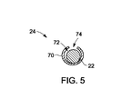
別の実施形態ではその支持構造24は、図5〜7に示したようなスロット付きチューブ70を含んでおり、このスロット付きチューブ70はチューブ60の様な完全収容式のチャンネルを形成していない。スロット付きチューブ70もチューブ60と同様に、その内部にギャップ72を提供するようにケーブル22の断面と比べてより大きな断面を有する。スロット付きチューブ70は、その周縁部に沿って軸方向に延びるスロット74を含む。スロット74は、スロット付きチューブ70の端部間に、以下で説明するような機械的な圧着を可能にするような空間を画定する。チューブ70も剛性の材料から形成させているが、スロット付きチューブ70内部にケーブル22を確保するように変形、圧縮または圧着を可能にするような材料特性または厚さを有することもあり得る。
In another embodiment, the
様々な実施形態ではそのケーブル22は図5に示すように、スロット付きチューブ70の内部に挿入されると共に、スロット付きチューブの内側表面の一部分に当たった状態に置かれている。図から理解できるように、スロット74の位置を含むケーブル22の周縁部の一部分に沿ってギャップ72が設けられている。次いでスロット74は、圧着用プライヤー(または、適当な別のデバイス)を用いて力学的な力を加え端部間の間隔を短縮させることなどによって押し合わされまたは圧着されており、これによりスロット74がより小さくなると共に、図6に示すようにスロット付きチューブ70内部にケーブル22が確保される。スロット付きチューブ70に圧力が加えられると、スロット付きチューブ70の構造も、その中を通過するように画定されたチャンネルの断面が円形ではなく若干長円形の形状となるように若干変形を受けることがあることに留意すべきである。しかし別の実施形態ではその断面は概ね円形の形状を維持している。
In various embodiments, the
図から理解できるように、スロット74を互いに近づけるように圧搾するために圧力が加えられた後においてもスロット付きチューブ70内部のケーブル22の位置が維持されるように、図6内のケーブル22の周縁部の大部分はスロット付きチューブ70の内側表面と接している。様々な実施形態ではスロット付きチューブ70に加えられる圧力によって、スロット付きチューブ70はケーブル22の周縁部のかなりの部分の周りで圧縮される。したがってケーブル22は、チューブ60と同様のフランジ40(図2参照)に対して確保し得るスロット付きチューブ70により画定される剛性のチャンネルの内部に維持される。
As can be seen from the figure, the position of the
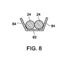
幾つかの実施形態では、例えば図8〜10に示したように支持構造24内部に複数のケーブル22を維持させることがある。これらの実施形態では、圧縮可能な支持構造80の内部に複数のケーブル22(図8〜10では2本のケーブル22を示している)が確保されている。ケーブル22は例えば、正及び負の電気接続ケーブルとすることができる。別の実施形態と同様に圧縮可能な支持構造80は、2本のケーブル22の断面と比べて(この実施形態では底部と側部において)より大きな断面を有する。圧縮可能な支持構造80を1つの平面状の底部82と2つの角度が付いた壁84を有するように図示しているが、圧縮可能な支持構造80も同じくスロット付きチューブ70と同様の実質的に円形の断面を有し得ることに留意すべきである。
In some embodiments,
圧縮可能な支持構造80は圧縮可能な壁84を含む。したがって圧縮可能な支持構造80はここでも剛性の材料から形成されているが、圧縮または圧着によって圧縮可能な支持構造80内部にケーブル22を確保することを可能とできるような材料特性や厚さを有することがある。
The
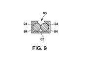
様々な実施形態では、ケーブル22は圧縮可能な支持構造80内部に挿入されると共に、図8に示すように圧縮可能な支持構造80の底部82の内側表面に当たった状態に置かれている。次いで角度が付いた壁84は、圧着用プライヤー(または、適当な別のデバイス)を用いて力学的な力を加え、角度が付いた壁84の両端間の間隔を短縮させることによって圧縮されて変形される(押し合わされるまたは圧着される)。例えば図9に示すように、角度が付いた壁84を圧縮した後に、ケーブル22の位置を平行配列に維持するように圧縮可能な支持構造80の断面がその内部に矩形のチャンネルを画定する概して矩形となるようにして角度が付いた壁84を変形させることがある。
In various embodiments, the
圧縮の後もスロット86は依然として存在しているが、ケーブル22は圧縮可能な支持構造80の内部の適所に確保されることに留意すべきである。圧縮可能な支持構造80に加えられる圧力は様々な実施形態では、ケーブル22が平行に整列して維持されるようにケーブル22の周りで圧縮可能な支持構造80を圧縮し変形させている。したがってケーブル22は、チューブ60と同様にフランジ40(図2参照)に対して確保し得る圧縮可能な支持構造80により画定される剛性のチャンネルの内部に維持されている。
It should be noted that the
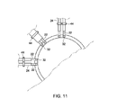
様々な実施形態に対する変形形態や修正形態も企図される。例えば圧縮可能な支持構造80ではなく、2本のケーブル22(または、これより多数のケーブル22)を平行な軸に沿って(円形のチューブと同様に)一体に保持するようにラッピング構造またはラッピング法が利用されることがある。動作時には、傾斜コイル30(図1参照)のパルス動作中などにおいて2本のケーブル22を通過して伝送されるパルスが相殺される。図11に示した別の例ではケーブル22の長さは、傾斜コイル端子32の位置などにおいて支持構造24から延び出ており、歪みを逃がすための柔軟性が提供される。支持構造24は、所望のまたは必要に応じた(例えば、異なる形状の断面を有するように)サイズ設定及び形状とすること、並びに所望のまたは必要に応じた(例えば、接続要件に基づいた)サイズ設定及び形状とすることがあることに留意すべきである。
Variations and modifications to the various embodiments are also contemplated. For example, rather than a
したがって、電気ケーブルをその内部に確保しているMRIシステムに対する支持及び装着機構が提供される。この支持構造は、ケーブルを支持すると共に振動などの動きに抗するための剛性を提供する。 Accordingly, a support and mounting mechanism for the MRI system that secures the electrical cable therein is provided. This support structure provides rigidity to support the cable and resist movement such as vibration.
様々な実施形態に従ったMRIシステム向けの支持付ケーブルを提供するための方法90を図12に示している。方法90は、電気ケーブルを支持構造内に挿入すること(92)を含む。この電気ケーブルは、適当な任意のケーブル(例えば、MRIシステムの1つまたは複数の傾斜コイルを制御するための電気信号を伝送することが可能なケーブルなど)とすることができる。様々な実施形態ではその支持構造は、ケーブルの周りに円周状のギャップを提供する一方でケーブルを完全にまたは部分的に囲繞する通路またはチャンネルを画定する剛性の構造である。
A
支持構造内部にケーブルを挿入するとそのケーブルは94において、支持構造によりケーブル全体またはケーブルの実質的にすべてが囲繞されてケーブルアセンブリが形成されるように確保される。例えばその支持構造は、ケーブルがチューブ内部でポッティングされるようにエポキシで満たされるチューブとすることがある。別の実施形態ではそのチューブは、1つまたは複数のケーブルがその内部で圧着留めされるようにスロット付きとすることがある。このケーブルアセンブリは、ケーブルのうちに支持構造の端部を超えて延びた可撓性の長さ部分を含むと共に、可撓性ケーブル部分を画定することがあることに留意すべきである。 Upon insertion of the cable within the support structure, the cable is secured at 94 such that the support structure surrounds the entire cable or substantially all of the cable to form a cable assembly. For example, the support structure may be a tube filled with epoxy so that the cable is potted inside the tube. In another embodiment, the tube may be slotted so that one or more cables are crimped therein. It should be noted that the cable assembly may include a flexible length portion of the cable that extends beyond the end of the support structure and may define a flexible cable portion.
このケーブルアセンブリは次いで96において、MRIシステム内部で結合されており、したがって例えば電源やパルス発生源(例えば、MRIシステムの外部にある)と傾斜コイルなどの内部の構成要素との間に電気接続を提供することが可能である。このケーブルアセンブリは、MRIシステム内部にあるマグネットフランジなど様々な静止部分に対して結合させることがある。 This cable assembly is then coupled at 96 within the MRI system, thus providing an electrical connection between, for example, a power source or pulse source (eg, external to the MRI system) and internal components such as gradient coils. It is possible to provide. This cable assembly may be coupled to various stationary parts such as a magnet flange inside the MRI system.
様々な実施形態の支持付ケーブル構造またはアセンブリは、図13に示すような撮像システム100などの異なるタイプの診断用医学撮像システムと接続させて設けられることがある。撮像システム100を単一モダリティの撮像システムとして図示しておりまたこれをMRIシステムとすることがあるが、様々な実施形態はマルチモダリティ撮像システム内にまたはこれに付属して実現し得ることを理解されたい。撮像システム100は、コンピュータ断層(CT)、陽電子放出断層(PET)、単一光子放出コンピュータ断層(SPECT)及び超音波システムなどの異なるタイプの医用撮像システムと組み合わせること、あるいは画像(特に人の画像)の作成が可能な別の任意のシステムと組み合わせることができる。さらに、これらの様々な実施形態は人を対象とした撮像のための医用撮像システムに限定されるものではなく、人間以外の対象、手荷物その他を撮像するための獣医学システムや非医用システムを含むこともある。
Various embodiments of supported cable structures or assemblies may be provided in connection with different types of diagnostic medical imaging systems, such as
図13を参照すると撮像システム100は、撮像ユニット104(例えば、撮像スキャナ)を有する撮像部分102と、プロセッサ108やその他のコンピュータ処理デバイスや制御器デバイスを含み得る処理部分106と、を含む。特に撮像ユニット104により撮像システム100は、対象物や患者114をスキャンして画像データ(対象物や患者114の全体の画像データのこともその一部の画像データのこともある)を収集することが可能となる。撮像ユニット104は、画像データの収集を可能とさせる1つまたは複数の撮像構成要素(その内部のマグネットや磁気巻き線など)を含んだガントリ110を含む。マルチモダリティ撮像システムでは、磁気共鳴撮像用のマグネット(複数のこともある)以外に、コンピュータ断層撮像用のX線源及び検出器、あるいは核医学撮像用のガンマカメラが設けられることがある。これらの撮像構成要素は、有線式やワイヤレス式とし得る通信リンク116を介して処理部分106に伝送される画像データを表す信号を発生させている。これらの信号は様々なプロトコルその他で構成され得ることに留意すべきである。さらに撮像ユニット104による撮像スキャンの間において、ガントリ110とその上またはその中に装着された撮像構成要素は静止したまま維持されることも、ボア112を通過する検査軸を規定する回転中心の周りでまたは回転中心に沿って回転させることもあり得ることにも留意すべきである。患者114は例えばモータ式テーブル118を用いてガントリ110の内部に位置決めされることがある。
Referring to FIG. 13, the
したがって動作時において、これらの撮像構成要素のうちの1つまたは幾つかの出力が処理部分106に送られる、またこの反対方向に送られており、これには例えば制御インタフェース120を介したプロセッサ108へのまたはこれからの信号の送信を含むことがある。プロセッサ108はさらに、例えばユーザ入力や所定のスキャンに基づいてモータ式テーブル118または撮像構成要素の位置を制御するための制御信号を発生させることもある。スキャン中に、撮像構成要素からの磁気共鳴画像データなどの画像データは、制御インタフェース120を介してデータインタフェース122を通してプロセッサ108に伝送されることがある。データの収集及び処理に使用されるプロセッサ108と付属のハードウェア及びソフトウェアとのことを、全体としてワークステーション124と呼ぶことがある。ワークステーション124は、ユーザ入力デバイス(キーボード126及び/またはマウス、ポインタその他などのその他の入力デバイス)と、モニタ128と、を含む。モニタ128は画像データを表示させると共に、タッチ画面が有効であればユーザから入力を受け取ることもある。
Thus, in operation, the output of one or several of these imaging components is sent to the
例証のみを目的として撮像システム100は、撮像部分102と、本明細書に記載したようなプロセッサまたはその他のコンピュータ処理デバイスや制御器デバイスを含み得る処理部分106と、を含むのが一般的である図14に示すようなMRIシステムとして実現させることがある。撮像システム100はガントリ110の内部に、マグネットコイル支持構造上に支持され得るコイルから形成した超伝導マグネット130を含むのが一般的である。超伝導マグネット130をヘリウム容器132(クライオスタットとも呼ぶ)が囲繞しており、またこれを液体ヘリウムで満たすことがある。この液体ヘリウムは、コールドヘッドスリーブ及び/または熱シールドを冷却するために利用されることがある。
For illustrative purposes only, the
ヘリウム容器132の外側表面と超伝導マグネット130の内側表面を囲繞するように断熱体134が設けられている。超伝導マグネット130の内部には複数の磁場傾斜コイル136が設けられており、またこの複数の磁場傾斜コイル136の内部にはRF送信コイル138が設けられている。例えば傾斜コイル30(図1参照)として具現化し得る磁場傾斜コイル136を含む撮像システム100内部にある構成要素には、本明細書により詳細に記載したような支持付ケーブルを用いて電気接続が設けられている。
A
幾つかの実施形態ではそのRF送信コイル138を1つの送信/受信コイルで置き換えることがある。ガントリ110内部にある構成要素は全体として撮像部分102を形成している。超伝導マグネット130を円筒状の形状としているが、その他の形状のマグネットも使用可能であることに留意すべきである。
In some embodiments, the RF transmit
処理部分106は、制御器140、主磁場制御142、傾斜磁場制御144、メモリ146、表示デバイス148、送信−受信(T−R)スイッチ150、RF送信器152及び受信器154を含むのが一般的である。
The
動作時において撮像対象の患者やファントームなどの対象の体部が、ボア112内の適当な支持体(例えば、患者テーブル)上に配置される。超伝導マグネット130はボア112を横断するような均一で静的な主磁場B0を発生させる。ボア112内及び対応した患者内の電磁場の強度は、主磁場制御142を介して制御器140により制御されており、制御器140はさらに超伝導マグネット130への励起電流の供給も制御している。
In operation, a subject body, such as a patient to be imaged or a phantom, is placed on a suitable support (eg, a patient table) in the
1つまたは複数の傾斜コイル素子を含む磁場傾斜コイル136は、超伝導マグネット130内部のボア112内で磁場B0に対して直交する3つの方向x、y及びzのうちの任意の1つまたは幾つかの方向に磁場傾斜が印加できるように設けられる。磁場傾斜コイル136は、傾斜磁場制御144によって励起を受けると共に、制御器140による制御も受けている。
The magnetic
複数のコイルを含み得るRF送信コイル138は、磁気パルスの送信かつ/または受信コイル素子(RF受信コイルとして構成された表面コイルなど)も設けられている場合は任意選択で同時に患者からのMR信号の検出を行うように配列されている。RF受信コイルは、任意のタイプまたは構成(例えば、単独の受信表面コイル)とすることがある。受信表面コイルは、RF送信コイル138内部に設けられたRFコイルからなるアレイとすることがある。
The RF transmit
RF送信コイル138と受信表面コイルはT−Rスイッチ150によって、RF送信器152や受信器154の1つに対してそれそれ選択的に相互接続させている。RF送信器152及びT−Rスイッチ150は、RF磁場パルスまたは信号をRF送信器152により発生させかつ患者内で磁気共鳴を励起するために患者に選択的に加えられるように制御器140によって制御される。RF励起パルスが患者に加えられている間は、T−Rスイッチ150はさらに受信表面コイルを受信器154から切断するように作動させている。
The
RFパルスの印加に続いて、再度T−Rスイッチ150を作動させてRF送信コイル138をRF送信器152から切断すると共に、受信表面コイルを受信器154に接続させている。受信表面コイルは、患者内の励起した原子核に由来するMR信号を検出または検知するように動作すると共に、このMR信号を受信器154に伝送している。検出したこれらのMR信号は一方、制御器140に伝送される。制御器140は、例えば患者の画像を表す信号を発生させるようにMR信号の処理を制御するプロセッサ(例えば、画像再構成プロセッサ)を含む。
Following the application of the RF pulse, the
画像を表す処理済み信号はさらに、表示デバイス148に送られ、画像の視覚的描出が提供される。具体的にはこのMR信号によって、観察可能な画像が得られるようにフーリエ変換を受けるk空間を満たすまたはこれを形成している。画像を表す処理済み信号は次いで、表示デバイス148に送れられる。
The processed signal representing the image is further sent to the
様々な実施形態及び/または構成要素(例えば、モジュールあるいはこれらの内部にある構成要素や制御器)はまた、1つまたは複数のコンピュータまたはプロセッサの一部として実現させることもある。このコンピュータやプロセッサは、コンピュータ処理デバイス、入力デバイス、表示ユニット、及び例えばインターネットにアクセスするためのインタフェースを含むことがある。このコンピュータやプロセッサは、マイクロプロセッサを含むことがある。このマイクロプロセッサは、通信バスと接続させることがある。このコンピュータやプロセッサはさらにメモリを含むことがある。このメモリは、ランダムアクセスメモリ(RAM)や読出し専用メモリ(ROM)を含むことがある。このコンピュータやプロセッサはさらに、ハードディスクドライブ、あるいは光ディスクドライブ、半導体ディスクドライブ(例えば、フラッシュRAM)その他などの取外し可能な記憶ドライブとし得る記憶デバイスを含むことがある。この記憶デバイスはさらに、コンピュータプログラムその他の命令をコンピュータやプロセッサにロードするための別の同様の手段とすることがある。 Various embodiments and / or components (eg, modules or components and controllers within them) may also be implemented as part of one or more computers or processors. The computer or processor may include a computer processing device, an input device, a display unit, and an interface for accessing the Internet, for example. The computer or processor may include a microprocessor. This microprocessor may be connected to a communication bus. The computer or processor may further include a memory. This memory may include random access memory (RAM) and read only memory (ROM). The computer or processor may further include a storage device that may be a hard disk drive or a removable storage drive, such as an optical disk drive, a semiconductor disk drive (eg, flash RAM), or the like. The storage device may also be another similar means for loading computer programs and other instructions into the computer or processor.
本明細書で使用する場合、「コンピュータ」や「モジュール」という用語は、マイクロコントローラを用いたシステム、縮小命令セットコンピュータ(RISC)、特定用途向け集積回路(ASIC)、論理回路、及び本明細書に記載した機能を実行可能な別の任意の回路やプロセッサを含めプロセッサベースまたはマイクロプロセッサベースの任意のシステムを含むことがある。上述の例は単に例示であり、またしたがっていかなる意味においても「コンピュータ」という用語の定義及び/または意味を限定することを意図していない。 As used herein, the terms “computer” and “module” refer to systems using microcontrollers, reduced instruction set computers (RISC), application specific integrated circuits (ASICs), logic circuits, and the present specification. May include any processor-based or microprocessor-based system, including any other circuit or processor capable of performing the functions described in. The above examples are exemplary only, and are therefore not intended to limit the definition and / or meaning of the term “computer” in any way.
このコンピュータやプロセッサは、入力データを処理するために1つまたは複数の記憶素子内に保存された1組の命令を実行する。この記憶素子はさらに、所望によりまたは必要に応じて、データやその他の情報も保存することがある。この記憶素子は情報ソースの形態とすることや、処理装置内部にある物理的な記憶素子とすることがある。 The computer or processor executes a set of instructions stored in one or more storage elements to process input data. The storage element may also store data and other information as desired or required. The storage element may be in the form of an information source or a physical storage element within the processing device.
この命令の組は、本発明の様々な実施形態の方法や処理などの指定の動作を実行するように処理装置としてのコンピュータまたはプロセッサに指令するための様々なコマンドを含むことがある。この命令組は、有形の非一時的コンピュータ読み取り可能媒体(複数のこともある)の一部を形成し得るソフトウェアプログラムの形態とすることがある。このソフトウェアは、システムソフトウェアやアプリケーションソフトウェアなどの様々な形態とすることがある。さらにこのソフトウェアは、単独のプログラムやモジュールからなる集合体、より大きなプログラムの内部のプログラムモジュール、あるいはプログラムモジュールの一部分の形態とすることがある。このソフトウェアはさらに、オブジェクト指向プログラミングの形態をしたモジュール型プログラミングを含むことがある。処理装置による入力データの処理は、オペレータコマンドに応答すること、以前の処理結果に応答すること、あるいは別の処理装置が発した要求に応答することがある。 This set of instructions may include various commands for instructing a computer or processor as a processing device to perform specified operations such as the methods and processes of the various embodiments of the present invention. This set of instructions may be in the form of a software program that may form part of a tangible non-transitory computer readable medium (s). This software may be in various forms such as system software and application software. Further, the software may be in the form of a collection of individual programs or modules, a program module within a larger program, or a portion of a program module. This software may further include modular programming in the form of object-oriented programming. Processing of input data by the processing device may respond to an operator command, respond to a previous processing result, or respond to a request issued by another processing device.
本明細書で使用する場合、「ソフトウェア」と「ファームウェア」という用語は置き換え可能であり、RAMメモリ、ROMメモリ、EPROMメモリ、EEPROMメモリ及び不揮発性RAM(NVRAM)メモリを含めコンピュータによって実行するためにメモリ内に保存された任意のコンピュータプログラムを含む。上述のメモリタイプは単に例示であり、またしたがってコンピュータプログラムの記憶に使用可能なメモリのタイプを限定するものではない。 As used herein, the terms “software” and “firmware” are interchangeable for execution by a computer, including RAM memory, ROM memory, EPROM memory, EEPROM memory, and non-volatile RAM (NVRAM) memory. Includes any computer program stored in memory. The memory types described above are merely exemplary and thus do not limit the types of memory that can be used to store computer programs.
上の記述は例示であって限定でないことを理解されたい。例えば上述の実施形態(及び/または、その態様)は、互いに組み合わせて使用することがある。さらに、具体的な状況や材料を様々な実施形態の教示に適応させるようにその趣旨を逸脱することなく多くの修正を実施することがある。本明細書内に記載した材料の寸法及びタイプが様々な実施形態のパラメータを規定するように意図していても、これらは決して限定ではなく単なる例示である。上の記述を検討することにより当業者には別の多くの実施形態が明らかとなろう。様々な実施形態の範囲はしたがって、添付の特許請求の範囲、並びに本請求範囲が規定する等価物の全範囲を参照しながら決定されるべきである。添付の特許請求の範囲では、「を含む(including)」や「ようになった(in which)」という表現を「を備える(comprising)」や「であるところの(wherein)」という対応する表現に対する平易な英語表現として使用している。さらに添付の特許請求の範囲では、「第1の」、「第2の」及び「第3の」その他の表現を単にラベル付けのために使用しており、その対象に対して数値的な要件を課すことを意図したものではない。さらに、添付の特許請求の範囲の限定は手段プラス機能形式で記載しておらず、また35 U.S.C.§112、第6パラグラフに基づいて解釈されるように意図したものでもない(ただし、本特許請求の範囲の限定によって「のための手段(means for)」の表現に続いて追加的な構造に関する機能排除の記述を明示的に用いる場合を除く)。 It should be understood that the above description is illustrative and not restrictive. For example, the above-described embodiments (and / or aspects thereof) may be used in combination with each other. In addition, many modifications may be made to adapt a particular situation or material to the teachings of the various embodiments without departing from the spirit thereof. Although the dimensions and types of materials described herein are intended to define the parameters of the various embodiments, these are by no means limiting and are merely exemplary. Many other embodiments will be apparent to those of skill in the art upon reviewing the above description. The scope of the various embodiments should therefore be determined with reference to the appended claims, along with the full scope of equivalents to which such claims define. In the appended claims, the expressions “including” and “in what” are used in conjunction with the corresponding expressions “comprising” and “where”. Is used as a plain English expression for. Further, in the appended claims, the “first”, “second” and “third” other expressions are merely used for labeling and numerical requirements for the subject matter. It is not intended to impose. Further, the limitations of the appended claims are not described in means-plus-functional form, and 35 U.S. Pat. S. C. 112, nor is it intended to be construed under the sixth paragraph (however, with respect to additional structure following the expression “means for” by limitation of the scope of the claims) Except when explicitly using the description of function exclusion).
この記載では、様々な実施形態(最適の形態を含む)を開示するため、並びに当業者による任意のデバイスやシステムの製作と使用及び組み込んだ任意の方法の実行を含む様々な実施形態の実施を可能にするために例を使用している。この様々な実施形態の特許性のある範囲は本特許請求の範囲によって規定していると共に、当業者により行われる別の例を含むことができる。こうした別の例は、その例が本特許請求の範囲の文字表記と異ならない構造要素を有する場合や、その例が本特許請求の範囲の文字表記と実質的に差がない等価的な構造要素を有する場合があるが、本特許請求の範囲の域内にあるように意図したものである。 In this description, various embodiments (including the best mode) are disclosed, as well as implementations of various embodiments, including the fabrication and use of any device or system and implementation of any method incorporated by those skilled in the art. Use examples to make it possible. The patentable scope of the various embodiments is defined by the claims, and may include other examples that occur to those skilled in the art. Such other examples may include structural elements that do not differ from the character representation of the claims, or equivalent structural elements that do not differ substantially from the character representation of the claims. Are intended to be within the scope of the claims.
20 ケーブル支持機構
22 ケーブル
24 支持構造
26 ギャップ
28 電源
30 コイル
32 コイル端子
40 フランジ
42 端子領域
44 留め具
46 ボア
48 インタフェース
50 ケーブル
52 ブラケット
54 内側支持構造
56 マグネットコイル支持構造
58 脚部
60 チューブ
62 エポキシ
64 開口部
70 チューブ
72 ギャップ
74 スロット
80 圧縮可能な支持構造
82 底部
84 壁
86 スロット
90 方法
92 支持構造内にケーブルを挿入する
94 ケーブルアセンブリを形成するためにケーブルの実質的にすべてを囲繞する支持構造内部にケーブルを確保する
96 電源を内部構成要素に接続するようにMRIシステム内部でケーブルアセンブリを結合させる
100 撮像システム
102 撮像部分
104 撮像ユニット
106 処理部分
108 プロセッサ
110 ガントリ
112 ボア
114 患者
116 通信リンク
118 モータ式テーブル
120 制御インタフェース
122 データインタフェース
124 ワークステーション
126 キーボード
128 モニタ
130 超伝導マグネット
132 ヘリウム容器
134 断熱体
136 磁場傾斜コイル
138 RF送信コイル
140 制御器
142 磁場制御
144 傾斜磁場制御
146 メモリ
148 表示デバイス
150 T−Rスイッチ
152 RF送信器
154 受信器
DESCRIPTION OF
Claims (10)
ある断面を有するチャンネルを画定する剛性の支持構造(24)と、
前記チャンネルの断面と比べてより小さい断面を有する前記剛性支持構造のチャンネルの内部に確保された電気ケーブル(22)であって、該剛性支持構造はその電気ケーブルを接続させる先の可動構成要素からの動きに抗するためにMRIシステムの静止構成要素に結合するように構成されている電気ケーブル(22)と、
を備えるケーブルアセンブリ(20)。 A cable assembly (20) for a magnetic resonance imaging (MRI) system comprising:
A rigid support structure (24) defining a channel having a cross-section;
An electrical cable (22) secured within a channel of the rigid support structure having a smaller cross section than the cross section of the channel, the rigid support structure from a movable component to which the electrical cable is connected An electrical cable (22) configured to couple to a stationary component of the MRI system to resist movement of
A cable assembly (20) comprising:
剛性のチューブ内部に電気ケーブルを挿入するステップ(92)と、
ケーブルアセンブリを形成するために剛性のチューブ内に電気ケーブルを確保するステップ(94)と、
電気ケーブルの一方の端部がMRIシステムの傾斜コイルの傾斜コイル端子に接続されるようにしてケーブルアセンブリをMRIシステムのマグネットフランジに結合させるステップ(96)と、
を含む方法(90)。 A method (90) for providing a supported cable for a magnetic resonance imaging (MRI) system comprising:
Inserting an electrical cable inside the rigid tube (92);
Securing an electrical cable within a rigid tube to form a cable assembly (94);
Coupling (96) the cable assembly to a magnetic flange of the MRI system such that one end of the electrical cable is connected to the gradient coil terminal of the gradient coil of the MRI system;
A method (90) comprising:
Applications Claiming Priority (2)
| Application Number | Priority Date | Filing Date | Title |
|---|---|---|---|
| US12/946,603 | 2010-11-15 | ||
| US12/946,603 US8735723B2 (en) | 2010-11-15 | 2010-11-15 | Apparatus and method for providing electric cables within a magnetic resonance imaging system |
Publications (3)
| Publication Number | Publication Date |
|---|---|
| JP2012105977A true JP2012105977A (en) | 2012-06-07 |
| JP2012105977A5 JP2012105977A5 (en) | 2014-12-11 |
| JP5923280B2 JP5923280B2 (en) | 2016-05-24 |
Family
ID=45999060
Family Applications (1)
| Application Number | Title | Priority Date | Filing Date |
|---|---|---|---|
| JP2011242975A Active JP5923280B2 (en) | 2010-11-15 | 2011-11-07 | Apparatus and method for providing an electrical cable within a magnetic resonance imaging system |
Country Status (4)
| Country | Link |
|---|---|
| US (1) | US8735723B2 (en) |
| JP (1) | JP5923280B2 (en) |
| DE (1) | DE102011055240A1 (en) |
| NL (1) | NL2007774C2 (en) |
Families Citing this family (13)
| Publication number | Priority date | Publication date | Assignee | Title |
|---|---|---|---|---|
| US8275429B1 (en) * | 2010-04-08 | 2012-09-25 | Stern Magnetics, LLC | High magnetic field gradient strength superconducting coil system |
| US9787750B2 (en) | 2011-12-31 | 2017-10-10 | Resonance Technology, Inc. | Universal interface system for MRI applications |
| US10018692B2 (en) | 2013-11-20 | 2018-07-10 | Aspect Imaging Ltd. | Shutting assembly for closing an entrance of an MRI device |
| DE202013011370U1 (en) | 2013-12-18 | 2014-01-30 | Aspect Imaging Ltd. | RF shielding connection in an MRI locking device |
| US10386432B2 (en) | 2013-12-18 | 2019-08-20 | Aspect Imaging Ltd. | Radiofrequency shielding conduit in a door or a doorframe of a magnetic resonance imaging room |
| DE202015100024U1 (en) * | 2014-01-29 | 2015-03-19 | Aspect Imaging Ltd. | Means for operating an MRI device in an RF magnetic environment |
| DE202014101102U1 (en) | 2014-03-09 | 2014-04-01 | Aspect Imaging Ltd. | An RF shielding MRI sheath |
| DE202014101104U1 (en) | 2014-03-09 | 2014-04-03 | Aspect Imaging Ltd. | A thermally insulating MRI sheath |
| JP6709218B2 (en) * | 2014-11-24 | 2020-06-10 | コーニンクレッカ フィリップス エヌ ヴェKoninklijke Philips N.V. | Routing optical data cable on patient table of MRI system |
| US10114092B2 (en) | 2015-08-07 | 2018-10-30 | General Electric Company | Connection system and method |
| DE102016211263A1 (en) * | 2016-06-23 | 2017-12-28 | Siemens Healthcare Gmbh | Cable for operating a gradient coil of a magnetic resonance device |
| US11029378B2 (en) | 2016-12-14 | 2021-06-08 | Aspect Imaging Ltd. | Extendable radiofrequency shield for magnetic resonance imaging device |
| US10401452B2 (en) | 2017-04-28 | 2019-09-03 | Aspect Imaging Ltd. | System for reduction of a magnetic fringe field of a magnetic resonance imaging device |
Citations (9)
| Publication number | Priority date | Publication date | Assignee | Title |
|---|---|---|---|---|
| JPS58153519U (en) * | 1982-04-06 | 1983-10-14 | 三菱重工業株式会社 | Cable support device |
| JP2001198101A (en) * | 2000-01-21 | 2001-07-24 | Toshiba Corp | Magnetic resonance imaging system |
| JP2004344182A (en) * | 2003-04-23 | 2004-12-09 | Hitachi Medical Corp | Magnetic resonance imaging apparatus |
| JP2007131237A (en) * | 2005-11-11 | 2007-05-31 | Toyota Motor Corp | Protection structure for high voltage cable |
| JP2008086613A (en) * | 2006-10-04 | 2008-04-17 | Hitachi Medical Corp | Magnetic resonance imaging apparatus |
| US20090267605A1 (en) * | 2008-04-29 | 2009-10-29 | Peter Dietz | Arrangement to connect gradient current feed lines in a magnetic resonance apparatus |
| JP2010125125A (en) * | 2008-11-28 | 2010-06-10 | Toshiba Corp | Magnetic resonance imaging apparatus |
| JP2011217778A (en) * | 2010-04-05 | 2011-11-04 | Hitachi Medical Corp | Magnetic resonance imaging apparatus |
| US20130090002A1 (en) * | 2011-10-05 | 2013-04-11 | Peter Dietz | Connecting Device for a Magnetic System of an Imaging System |
Family Cites Families (22)
| Publication number | Priority date | Publication date | Assignee | Title |
|---|---|---|---|---|
| US4731502A (en) * | 1986-10-21 | 1988-03-15 | W. L. Gore & Associates, Inc. | Limited bend-radius transmission cable also having controlled twist movement |
| JPH01262852A (en) | 1988-04-13 | 1989-10-19 | Hitachi Ltd | Probe coil for mri |
| US5159929A (en) | 1990-06-14 | 1992-11-03 | Morris G Ronald | Insulated rf shield |
| US6556012B2 (en) | 2000-01-21 | 2003-04-29 | Kabushiki Kaisha Toshiba | Magnetic resonance imaging apparatus |
| US6933722B2 (en) | 2000-07-05 | 2005-08-23 | Hitachi Medical Corporation | Magnetic resonance imaging device and gradient magnetic field coil used for it |
| US6867593B2 (en) | 2002-11-22 | 2005-03-15 | Igc-Medical Advances, Inc. | Modular local coil set for magnetic resonance imaging |
| US7307421B2 (en) | 2003-04-23 | 2007-12-11 | Hitachi Medical Corporation | Magnetic resonance imaging device |
| JP4250468B2 (en) | 2003-07-14 | 2009-04-08 | 株式会社日立メディコ | Magnetic resonance imaging system |
| DE102004047991A1 (en) * | 2003-10-02 | 2005-06-23 | Aisan Kogyo K.K., Obu | Rotary angle sensors |
| EP1712926B1 (en) * | 2004-02-02 | 2011-11-02 | Aisan Kogyo Kabushiki Kaisha | Rotating angle sensor, method of manufacturing the sensor, and throttle control device having the rotating angle sensor |
| WO2006103591A1 (en) | 2005-03-31 | 2006-10-05 | Koninklijke Philips Electronics N.V. | Mri system comprising a scan room interface for a/d-conversion of mr signals between a receiver coil unit and a remote signal processing unit |
| DE102005015393A1 (en) | 2005-04-04 | 2006-07-20 | Siemens Ag | Magnet resonance device for medical treatment, comprises construction unit, paneling shifted interwirings connected by hardened holding/bonding agent with the construction unit |
| US7382132B1 (en) | 2005-04-29 | 2008-06-03 | General Electric Company | 6-channel array coil for magnetic resonance imaging |
| DE102005034914B4 (en) | 2005-07-26 | 2009-07-30 | Siemens Ag | Supply line for a local coil |
| US8324899B2 (en) | 2005-10-06 | 2012-12-04 | Koninklijke Philips Electronics N.V. | MR coil with fiber optical connection |
| US7345485B2 (en) | 2006-01-18 | 2008-03-18 | Koninklijke Philips Electronics N.V. | Optical interface for local MRI coils |
| CA2574859C (en) * | 2007-01-23 | 2013-12-10 | Flextherm Inc. | Encapsulating permanent wire connector |
| GB0709114D0 (en) | 2007-05-11 | 2007-06-20 | Pulseteq Ltd | Apparatus and method for magnetic resonance scanning |
| US7498814B1 (en) | 2007-10-31 | 2009-03-03 | General Electric Company | Magnet assembly for magnetic resonance imaging system |
| JP2010027453A (en) * | 2008-07-22 | 2010-02-04 | Hitachi Cable Ltd | Cable with crimping terminal, and manufacturing method thereof |
| US20100137704A1 (en) | 2008-12-02 | 2010-06-03 | Surgivision, Inc. | Medical mats with electrical paths and methods for using the same |
| WO2010096179A2 (en) | 2009-02-20 | 2010-08-26 | Surgivision, Inc. | Cable management systems for mri systems and related methods |
-
2010
- 2010-11-15 US US12/946,603 patent/US8735723B2/en active Active
-
2011
- 2011-11-07 JP JP2011242975A patent/JP5923280B2/en active Active
- 2011-11-10 DE DE102011055240A patent/DE102011055240A1/en not_active Withdrawn
- 2011-11-11 NL NL2007774A patent/NL2007774C2/en not_active IP Right Cessation
Patent Citations (9)
| Publication number | Priority date | Publication date | Assignee | Title |
|---|---|---|---|---|
| JPS58153519U (en) * | 1982-04-06 | 1983-10-14 | 三菱重工業株式会社 | Cable support device |
| JP2001198101A (en) * | 2000-01-21 | 2001-07-24 | Toshiba Corp | Magnetic resonance imaging system |
| JP2004344182A (en) * | 2003-04-23 | 2004-12-09 | Hitachi Medical Corp | Magnetic resonance imaging apparatus |
| JP2007131237A (en) * | 2005-11-11 | 2007-05-31 | Toyota Motor Corp | Protection structure for high voltage cable |
| JP2008086613A (en) * | 2006-10-04 | 2008-04-17 | Hitachi Medical Corp | Magnetic resonance imaging apparatus |
| US20090267605A1 (en) * | 2008-04-29 | 2009-10-29 | Peter Dietz | Arrangement to connect gradient current feed lines in a magnetic resonance apparatus |
| JP2010125125A (en) * | 2008-11-28 | 2010-06-10 | Toshiba Corp | Magnetic resonance imaging apparatus |
| JP2011217778A (en) * | 2010-04-05 | 2011-11-04 | Hitachi Medical Corp | Magnetic resonance imaging apparatus |
| US20130090002A1 (en) * | 2011-10-05 | 2013-04-11 | Peter Dietz | Connecting Device for a Magnetic System of an Imaging System |
Also Published As
| Publication number | Publication date |
|---|---|
| JP5923280B2 (en) | 2016-05-24 |
| NL2007774A (en) | 2012-05-16 |
| US20120118630A1 (en) | 2012-05-17 |
| NL2007774C2 (en) | 2013-01-22 |
| DE102011055240A1 (en) | 2012-05-16 |
| US8735723B2 (en) | 2014-05-27 |
| CN102565729A (en) | 2012-07-11 |
Similar Documents
| Publication | Publication Date | Title |
|---|---|---|
| JP5923280B2 (en) | Apparatus and method for providing an electrical cable within a magnetic resonance imaging system | |
| US9599686B2 (en) | Systems and methods for coil arrangements in magentic resonance imaging | |
| US8797030B2 (en) | Magnetic resonance radio-frequency coil and method of manufacturing | |
| US8474572B2 (en) | Apparatus and method to attenuate vibration and acoustic noise | |
| US20130256559A1 (en) | Method and apparatus for aligning a multi-modality imaging system | |
| JP5989970B2 (en) | System and method for removing heat generated by a heat sink of a magnetic resonance imaging system | |
| JP4785566B2 (en) | Magnetic resonance imaging apparatus and magnetic resonance imaging method | |
| JP6042644B2 (en) | Coil support for magnetic resonance imaging (MRI) magnet and support method | |
| US8415952B2 (en) | Superconducting magnet coil interface and method providing coil stability | |
| US20120146643A1 (en) | Radio frequency coil and apparatus | |
| US8710842B2 (en) | Apparatus and method to reduce noise in magnetic resonance imaging systems | |
| JP4350729B2 (en) | Imaging apparatus and imaging method | |
| US20130300417A1 (en) | Systems and methods for noise control in a medical imaging system | |
| WO2017119994A1 (en) | Methods and systems for correcting k-space trajectories | |
| JP5763891B2 (en) | Magnetic resonance imaging system | |
| CN111090066A (en) | Radio frequency coil and shield in magnetic resonance imaging method and apparatus | |
| US9778333B2 (en) | Magnetic resonance (MR) imaging generating perfusion images with arterial spin labeling (ASL) and 3D radial pulse sequences | |
| US9297867B2 (en) | Radio frequncy (RF) body coil and method for tuning an RF body coil for magnetic resonance imaging | |
| CN102565729B (en) | For providing equipment and the method for cable in magnetic resonance imaging system | |
| US20230206427A1 (en) | Backend sequence kernel | |
| US11609292B2 (en) | Device and method for nuclear magnet resonance spectroscopy | |
| JP2007289344A (en) | Magnetic resonance imaging apparatus | |
| JP2012115456A (en) | Magnetic resonance imaging apparatus |
Legal Events
| Date | Code | Title | Description |
|---|---|---|---|
| A521 | Request for written amendment filed |
Free format text: JAPANESE INTERMEDIATE CODE: A523 Effective date: 20141028 |
|
| A621 | Written request for application examination |
Free format text: JAPANESE INTERMEDIATE CODE: A621 Effective date: 20141028 |
|
| A977 | Report on retrieval |
Free format text: JAPANESE INTERMEDIATE CODE: A971007 Effective date: 20150729 |
|
| A131 | Notification of reasons for refusal |
Free format text: JAPANESE INTERMEDIATE CODE: A131 Effective date: 20150811 |
|
| A521 | Request for written amendment filed |
Free format text: JAPANESE INTERMEDIATE CODE: A523 Effective date: 20151006 |
|
| TRDD | Decision of grant or rejection written | ||
| A01 | Written decision to grant a patent or to grant a registration (utility model) |
Free format text: JAPANESE INTERMEDIATE CODE: A01 Effective date: 20160329 |
|
| A61 | First payment of annual fees (during grant procedure) |
Free format text: JAPANESE INTERMEDIATE CODE: A61 Effective date: 20160418 |
|
| R150 | Certificate of patent or registration of utility model |
Ref document number: 5923280 Country of ref document: JP Free format text: JAPANESE INTERMEDIATE CODE: R150 |
|
| R250 | Receipt of annual fees |
Free format text: JAPANESE INTERMEDIATE CODE: R250 |
|
| R250 | Receipt of annual fees |
Free format text: JAPANESE INTERMEDIATE CODE: R250 |
|
| R250 | Receipt of annual fees |
Free format text: JAPANESE INTERMEDIATE CODE: R250 |
|
| R250 | Receipt of annual fees |
Free format text: JAPANESE INTERMEDIATE CODE: R250 |
|
| R250 | Receipt of annual fees |
Free format text: JAPANESE INTERMEDIATE CODE: R250 |
|
| R250 | Receipt of annual fees |
Free format text: JAPANESE INTERMEDIATE CODE: R250 |