JP2012105107A - Antenna device and antenna bracket - Google Patents
Antenna device and antenna bracket Download PDFInfo
- Publication number
- JP2012105107A JP2012105107A JP2010252432A JP2010252432A JP2012105107A JP 2012105107 A JP2012105107 A JP 2012105107A JP 2010252432 A JP2010252432 A JP 2010252432A JP 2010252432 A JP2010252432 A JP 2010252432A JP 2012105107 A JP2012105107 A JP 2012105107A
- Authority
- JP
- Japan
- Prior art keywords
- antenna
- elevation angle
- angle adjustment
- clamp
- connection portion
- Prior art date
- Legal status (The legal status is an assumption and is not a legal conclusion. Google has not performed a legal analysis and makes no representation as to the accuracy of the status listed.)
- Granted
Links
Images


Abstract
Description
本発明は、アンテナを支柱の側方に突き出す状態でアンテナを支柱に固定するアンテナ装置及びアンテナ取付金具に関し、特に、通信用の電気部品を収容した収容ボックスが背面に装着されたアンテナを固定する装置等に関する。 The present invention relates to an antenna device and an antenna mounting bracket for fixing an antenna to a column in a state in which the antenna protrudes to the side of the column, and in particular, fixes an antenna in which a storage box containing electrical components for communication is mounted on the back surface. It relates to devices.
支柱へのパラボラアンテナ(以下、「アンテナ」という)の取り付けに際しては、アンテナを固定するだけでなく、アンテナが適切な方向を向くように向きを調整する必要があるため、アンテナを仰角方向や方位角方向に動かすための機構をアンテナ取付金具に設ける必要がある。 When attaching a parabolic antenna (hereinafter referred to as “antenna”) to a support, it is necessary not only to fix the antenna, but also to adjust the orientation so that the antenna faces the appropriate direction. It is necessary to provide a mechanism for moving in the angular direction on the antenna mounting bracket.
この種のアンテナ取付金具を用いたアンテナ装置として、例えば、特許文献1には、図11に示すように、支柱60を中心に挟んで対向して配設されるとともに、支柱60の高さ方向の上下に分割され、各々が支柱60の高さ方向及び支柱回り方向に調整自在に固定される上クランプ61、62及び下クランプ63、64からなる本体固定部65と、上クランプ61に仰角回転軸66を中心にして回転可能に取り付けられ、かつ、アンテナ67に固着されるアンテナ金具68と、上クランプ61の長孔69と下クランプ63のねじ孔70の間を螺動し、上クランプ61、62を押し引きする方位角調整ボルト71と、アンテナ金具68の係合孔72と上クランプ61のナット部73の間を螺動し、アンテナ金具68を押し引きする仰角調整ボルト74とを備えたアンテナ装置が記載されている。
As an antenna device using this type of antenna mounting bracket, for example, in
上記アンテナ装置においては、上クランプ61、62及び下クランプ63、64の各々で支柱60を締め付けることで、上下のクランプ61〜64を支柱60に固定し、アンテナ67を強固に固定する。また、アンテナ67の方位角を調整する場合には、上クランプ61、62の締め付けを緩めた上で、方位角調整ボルト71を通じて上クランプ61、62を支柱60の軸回りに回動させ、アンテナ67を方位角方向に回動させる。さらに、アンテナ67の仰角を調整する場合には、固定ボルト75を緩めた上で、仰角回転軸66を支軸としてアンテナ金具68を回動させ、アンテナ67を仰角方向に回動させる。
In the antenna device, the
ところで、取付金具によって取り付けたアンテナを無線通信機器として利用するには、アンテナをケーブルや導波管等の通信用の電気部品と電気的に接続することが必要である。このため、アンテナの設置に際しては、アンテナ固定用の取付金具とは別に、電気部品を支柱に固定するための取付金具が必要となり、部品点数を増大させる一因となる。 By the way, in order to use an antenna attached by a mounting bracket as a wireless communication device, it is necessary to electrically connect the antenna to electrical components for communication such as a cable and a waveguide. For this reason, when installing the antenna, a mounting bracket for fixing the electrical component to the support is required in addition to the mounting bracket for fixing the antenna, which increases the number of components.
そこで、近年、図12に示すように、通信用の電気部品を収容した収容ボックス82をアンテナ81の背面に装着し、アンテナ81と収容ボックス(電気部品)82を一体化した一体型アンテナ83が提案されている。この一体型アンテナ83では、連結部84を通じて、収容ボックス82とアンテナ81が機械的に連結されると同時に、収容ボックス82内の電気部品がアンテナ81と電気的に接続される。これにより、電気部品用の取付金具を不要とし、部品点数の削減を図っている。
Therefore, in recent years, as shown in FIG. 12, an integrated
図12に示すアンテナ装置において、アンテナ81の仰角を調整するにあたっては、クランプ85と仰角調整金具89を連結する締結ねじ86を工具87によって緩め、その上で、仰角調整金具89、収容ボックス82及びアンテナ81の全体を仰角方向に回動させ、位置が定まった時点で締結ねじ86を締め直すことになる。
In the antenna apparatus shown in FIG. 12, when adjusting the elevation angle of the
しかし、同図に示すように、収容ボックス82の大きさによっては、締結ねじ86を締緩するための作業空間を収容ボックス82が占有し、アンテナ施工工事の際の調整作業に多大な手間を要するという問題がある。
However, as shown in the figure, depending on the size of the
そこで、例えば、図13に示すように、仰角調整金具89の横方向の長さを延伸させることで、締結ねじ86と収容ボックス82の間の空間を拡大し、作業空間の確保を図ることが考えられる。しかし、この場合、仰角調整金具89の横方向の長さを延伸させた分、支柱88とアンテナ81の距離Lを拡げることになり、アンテナ設置後の指向方向のずれを招くという問題がある。
Therefore, for example, as shown in FIG. 13, the space between the
すなわち、距離Lを拡げてアンテナ81を遠ざけた分、アンテナ81に風を受けた際に生じる回転モーメント(支柱88の軸線回りの回転:矢印M参照)が増大するため、アンテナ81が方位角方向に回り易くなり、アンテナ81の設置後にアンテナ81の向きが変動する虞がある。特に、近年、送信出力の増大化が進んでアンテナが大きくなる傾向にあり、風の影響を受け易くなっているため、上記の問題は軽視できないものとなる。
That is, as the distance L is increased and the
また、図13に示すアンテナ装置では、アンテナ81をクランプ85から遠ざけることになるため、クランプ85や仰角調整金具89に加わる負荷が増大する。このため、鉛直方向の荷重(例えば、アンテナ81への積雪等による荷重)への耐性が低くなり、アンテナ落下事故の危険性を増大させることになる。そして、このような事故を防ぐためには、アンテナ取付金具の剛性強化が避けられず、取付構造の大型化や材料の見直しなどが必要となり、全体の重量増や製造コストの増加を強いられることになる。
In the antenna device shown in FIG. 13, the
そこで、本発明は、上記従来の技術における問題点に鑑みてなされたものであって、仰角調整の際の良好な作業性を確保しつつ、回転モーメントの増大、鉛直方向の荷重に対する耐性の低下、及び重量やコストの増加を回避することが可能なアンテナ装置等を提供することを目的とする。 Therefore, the present invention has been made in view of the problems in the above-described conventional technology, and while ensuring good workability at the time of adjusting the elevation angle, the rotational moment is increased and the resistance to a load in the vertical direction is reduced. An object of the present invention is to provide an antenna device that can avoid an increase in weight and cost.
上記目的を達成するため、本発明は、アンテナと、該アンテナの背面に装着され、通信用の電気部品を収容する収容部と、該収容部が装着された状態のアンテナを、該アンテナが支柱の側方に突出する状態で該支柱に固定するアンテナ取付金具とを備えたアンテナ装置であって、前記アンテナ取付金具が、前記支柱に締め付け固定されるクランプと、該クランプ及び前記アンテナを連結するとともに、該アンテナの仰角を調整するための仰角調整操作部を該クランプとの接続部に有する仰角調整金具とを備え、前記仰角調整操作部が、前記収容部と異なる高さに位置することを特徴とする。 In order to achieve the above object, the present invention provides an antenna, a receiving portion that is attached to the back surface of the antenna and contains electrical components for communication, and an antenna in a state in which the receiving portion is attached. An antenna device including an antenna mounting bracket that is fixed to the column in a state of protruding to the side of the antenna, wherein the antenna mounting bracket connects the clamp and the antenna to a clamp that is clamped and fixed to the column. And an elevation angle adjustment fitting having an elevation angle adjustment operation portion for adjusting the elevation angle of the antenna at a connection portion with the clamp, wherein the elevation angle adjustment operation portion is located at a different height from the housing portion. Features.
そして、本発明によれば、仰角調整操作部が収容部と異なる高さに位置するため、仰角調整の際の良好な作業性を確保しつつ、回転モーメントの増大、鉛直方向の荷重に対する耐性の低下、及び重量やコストの増加を回避することが可能になる。 According to the present invention, since the elevation angle adjustment operation part is located at a different height from the housing part, it is possible to increase the rotational moment and to withstand the load in the vertical direction while ensuring good workability during the adjustment of the elevation angle. It is possible to avoid a decrease and an increase in weight and cost.
上記アンテナ装置において、前記仰角調整操作部の下端部が、前記収容部の上端部よりも上方に位置するように構成することができる。 The antenna apparatus may be configured such that a lower end portion of the elevation angle adjusting operation portion is positioned above an upper end portion of the housing portion.
上記アンテナ装置において、前記アンテナの背面に付設されたアンテナ接続部を備え、該アンテナ接続部が、連結部を通じて前記収容部が接続される第1の接続部と、該第1の接続部の上方に形成され、前記仰角調整金具が接続される第2の接続部とを備え、前記アンテナの背面に前記収容部を装着した状態で、前記第2の接続部が前記連結部の上端部よりも上方に位置するように構成することができる。 The antenna device includes an antenna connection portion attached to a back surface of the antenna, the antenna connection portion including a first connection portion to which the housing portion is connected through a connecting portion, and an upper portion of the first connection portion. And the second connecting portion is attached to the back surface of the antenna, and the second connecting portion is more than the upper end of the connecting portion. It can be configured to be located above.
上記構成によれば、アンテナに対する連結部の取付位置と、アンテナに対する仰角調整金具の取付位置とを上下に並べることができ、アンテナ、連結部及び仰角調整金具を適切に連結しつつ、仰角調整操作部の下端部を収容部の上端部よりも上方に位置させることが可能になる。 According to the above configuration, the mounting position of the connecting portion with respect to the antenna and the mounting position of the elevation angle adjusting bracket with respect to the antenna can be arranged vertically, and the elevation angle adjusting operation is performed while appropriately connecting the antenna, the connecting portion, and the elevation adjusting bracket. It becomes possible to position the lower end part of a part above the upper end part of an accommodating part.
上記アンテナ装置において、前記仰角調整操作部の上端部が、前記収容部の下端部よりも下方に位置するように構成することができる。 In the antenna device, an upper end portion of the elevation angle adjusting operation unit can be configured to be positioned below a lower end portion of the housing unit.
上記アンテナ装置において、前記アンテナの背面に付設されたアンテナ接続部を備え、該アンテナ接続部が、連結部を通じて前記収容部が接続される第1の接続部と、該第1の接続部の下方に形成され、前記仰角調整金具が接続される第2の接続部とを備え、前記アンテナの背面に前記収容部を装着した状態で、前記第2の接続部が前記連結部の下端部よりも下方に位置するように構成することができる。 The antenna device includes an antenna connection portion attached to a back surface of the antenna, wherein the antenna connection portion includes a first connection portion to which the housing portion is connected through a connecting portion, and a lower portion of the first connection portion. And the second connection portion is connected to the back surface of the antenna, and the second connection portion is lower than the lower end portion of the coupling portion. It can comprise so that it may be located below.
上記構成によれば、アンテナに対する連結部の取付位置と、アンテナに対する仰角調整金具の取付位置とを上下に並べることができ、アンテナ、連結部及び仰角調整金具を適切に連結しつつ、仰角調整操作部の上端部を収容部の下端部よりも下方に位置させることが可能になる。 According to the above configuration, the mounting position of the connecting portion with respect to the antenna and the mounting position of the elevation angle adjusting bracket with respect to the antenna can be arranged vertically, and the elevation angle adjusting operation is performed while appropriately connecting the antenna, the connecting portion, and the elevation adjusting bracket. It becomes possible to position the upper end part of a part below the lower end part of an accommodating part.
上記アンテナ装置において、前記アンテナ接続部と前記仰角調整金具を一体に形成することができる。 In the antenna device, the antenna connection portion and the elevation angle adjusting bracket can be integrally formed.
また、本発明は、アンテナと、該アンテナの背面に装着され、通信用の電気部品を収容する収容部と、該収容部が装着された状態のアンテナを、該アンテナが支柱の側方に突出する状態で該支柱に固定するアンテナ取付金具とを備えたアンテナ装置であって、前記アンテナ取付金具が、前記支柱に締め付け固定されるクランプと、該クランプ及び前記アンテナを連結するとともに、該アンテナの仰角を調整するための仰角調整操作部を該クランプとの接続部に有する仰角調整金具とを備え、前記支柱の中心軸と直交しつつ、仰角調整軸を通過する平面を仰角調整中心平面と定義するとともに、該仰角調整中心平面及び前記支柱の中心軸の交点と前記アンテナの中心軸とを通過する平面をアンテナ中心平面と定義したときに、前記仰角調整中心平面と前記アンテナ中心平面が斜めに交差することを特徴とする。 In addition, the present invention provides an antenna, a housing portion that is mounted on the back surface of the antenna and that houses electrical components for communication, and an antenna in a state in which the housing portion is mounted. An antenna mounting bracket that is fixed to the column in a state where the antenna mounting bracket is clamped and fixed to the column, and the clamp and the antenna are connected together. An elevation angle adjustment fitting having an elevation angle adjustment operation part for adjusting an elevation angle at a connection part with the clamp, and defining a plane that passes through the elevation angle adjustment axis while being orthogonal to the center axis of the column as an elevation angle adjustment center plane And the elevation angle adjustment center when a plane that passes through the intersection of the elevation angle adjustment center plane and the center axis of the support column and the center axis of the antenna is defined as an antenna center plane. Characterized in that surface and the antenna center plane intersects obliquely.
さらに、本発明は、通信用の電気部品を収容した収容部が背面に装着されたアンテナを、該アンテナが支柱の側方に突出する状態で該支柱に固定するアンテナ取付金具であって、前記支柱に締め付け固定されるクランプと、該クランプ及び前記アンテナを連結するとともに、該アンテナの仰角を調整するための仰角調整操作部を該クランプとの接続部に有する仰角調整金具とを備え、前記仰角調整操作部が、前記収容部と異なる高さに位置することを特徴とする。 Furthermore, the present invention is an antenna mounting bracket for fixing an antenna mounted on the back side with a housing portion containing electrical components for communication, to the support column in a state where the antenna projects to the side of the support column, A clamp that is clamped and fixed to a support; and an elevation angle adjustment fitting that connects the clamp and the antenna and has an elevation angle adjustment operation unit for adjusting an elevation angle of the antenna at a connection portion with the clamp, and the elevation angle The adjustment operation part is located at a different height from the housing part.
以上のように、本発明によれば、仰角調整の際の良好な作業性を確保しつつ、回転モーメントの増大、鉛直方向の荷重に対する耐性の低下、及び重量やコストの増加を回避することが可能になる。 As described above, according to the present invention, it is possible to avoid an increase in rotational moment, a decrease in resistance to a load in the vertical direction, and an increase in weight and cost while ensuring good workability in adjusting the elevation angle. It becomes possible.
次に、発明を実施するための形態について、図面を参照しながら詳細に説明する。 Next, modes for carrying out the invention will be described in detail with reference to the drawings.
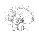
図1〜図6は、本発明にかかるアンテナ装置の第1の実施形態を示し、このアンテナ装置1は、大別して、アンテナ2と、通信用の電気部品を収容する略角柱状の収容ボックス3と、これらアンテナ2及び収容ボックス3を支柱4に固定するアンテナ取付金具5とから構成される。
1 to 6 show a first embodiment of an antenna device according to the present invention. The
図3に示すように、アンテナ2の背面2aには、アンテナ2をアンテナ取付金具5及び収容ボックス3と連結するためのアンテナ接続部6が付設される。このアンテナ接続部6は、略円状に形成された第1の接続部6aと、略三角状に形成された第2の接続部6bとが一体に形成されて構成される。
As shown in FIG. 3, an
アンテナ2への収容ボックス3の連結は、連結部8の端部に設けた接続板9(図5参照)をアンテナ接続部6の第1の接続部6aに接続し、アンテナ接続部6の第2の接続部6bを連結部8の上端よりも上方に突出させるようにして行う。これにより、アンテナ2の後方に収容ボックス3を装着し、一体型アンテナ10を構成する。
The
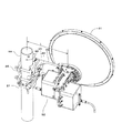
アンテナ取付金具5は、図1に示すように、アンテナ2及び収容ボックス3を支柱4に固定するために設けられ、アンテナ2を支柱4の側方に突き出す状態で固定するように構成される。このアンテナ取付金具5は、大別して、クランプ11と、一端がクランプ11と連結されるとともに、他端がアンテナ2と連結される仰角調整金具12とから構成される。
As shown in FIG. 1, the antenna mounting bracket 5 is provided to fix the
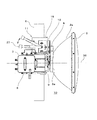
クランプ11は、相対向して配置される押さえ金具14及び受け金具15と、両者を連結するボルト16及びナット17とを備える。押さえ金具14は、上面視山括弧状に形成され、一方、受け金具15は、支柱4の周面と対向する面が谷状に形成されるとともに、反対側の面15aが平坦状に形成される。図2に示すように、受け金具15の平坦面15aには、側方に突出する3本のボルト18a〜18cが植設されるとともに、弓長状の貫通孔20が穿設される。貫通孔20には、支柱4との対向面(平坦面15aと反対側の面)側からボルト18dが挿通される。
The
上記のクランプ11では、押さえ金具14及び受け金具15の間に支柱4を挟んで締め付けることにより、アンテナ2及び収容ボックス3を支柱4に固定する。尚、押さえ金具14と受け金具15の間隔は、ナット17の締め具合を調整することで拡縮することができ、支柱4の径に応じて適宜調整することが可能である。
In the
仰角調整金具12は、アンテナ2の仰角を調整可能としつつ、アンテナ2及び収容ボックス3をクランプ11に連結するために設けられる。この仰角調整金具12は、上面視L字状を有し、図2及び図4に示すように、受け金具15の平坦面15aと平行に位置する短板部21と、短板部21に直交する長板部22とを備える。
The elevation
図4に示すように、短板部21には、平坦面15aから突出するボルト18a(図2参照)を挿通する貫通孔23aと、ボルト18b、18cを挿通する弓長状の貫通孔23b、23cと、ボルト18dを挿通する貫通孔23d〜23fとが穿設される。仰角調整金具12とクランプ11の固定は、図1及び図2に示すように、ボルト18a〜18cを貫通孔23a〜23cの各々に挿通しつつ、その時点での仰角調整金具12の傾きに応じてボルト18dを貫通孔23d〜23fの何れかに挿通し、ボルト18a〜18dにナット19a〜19dを螺合して締め付けることで行う。
As shown in FIG. 4, the
図4に示すように、長板部22には、X状に配列された5個の貫通孔24a〜24eが穿設される。仰角調整金具12とアンテナ2の固定は、貫通孔24a〜24eのうちの中央に位置する貫通孔24cと、下部に位置する貫通孔24d、24eとの3個の貫通孔に、取付ねじ25a〜25c(図1参照)を挿通し、その状態で、取付ねじ25a〜25cの先端を、アンテナ接続部6の第2の接続部6bに設けた3個のねじ孔26a〜26c(図3参照)に螺入することで行う。
As shown in FIG. 4, the
仰角調整金具12において、アンテナ2の仰角を調整するにあたっては、工具27(図5参照)を用いて、ボルト18a〜18dと螺合するナット19a〜19dを緩め、仰角調整金具12とクランプ11(受け金具15)との締結を解除する。そして、ボルト18aを支軸として仰角調整金具12を回動させ、アンテナ2の仰角を適切な角度に調整する。アンテナ角度の調整後、ナット19a〜19dを締め直し、仰角調整金具12とクランプ11を固定する。
In adjusting the elevation angle of the
尚、押さえ金具14、受け金具15及び仰角調整金具12等の金属部材は、ダイカスト鋳物等の金型を用いた成形法によって形成することができるが、板金、切削加工等の他の成形法、材質によって得られる構造であってもよい。 The metal members such as the holding metal fitting 14, the receiving metal fitting 15, and the elevation angle adjusting metal fitting 12 can be formed by a forming method using a die such as a die-casting casting, but other forming methods such as sheet metal and cutting, The structure obtained by a material may be sufficient.
上記構成を有するアンテナ装置1では、図1〜図6に示すように、アンテナ接続部6、連結部8及び仰角調整金具12の三者の連結部分において、アンテナ2に対する連結部8の取付位置と、アンテナ2に対する仰角調整金具12の取付位置とを上下に並べ、図7に示すように、ナット19c(仰角調整する際に操作を要する箇所の下端部28)を収容ボックス3の上端部29よりも上方に位置させる。
In the
このため、図1に示すように、ナット19a〜19dを締緩するための作業空間を収容ボックス3によって占有されることがなく、アンテナ2、収容ボックス3及びアンテナ取付金具5の三者を連結させた状態でも、十分な作業空間を確保することができる。これにより、良好な作業性を確保することができ、調整作業の際の負担増を回避することが可能になる。
For this reason, as shown in FIG. 1, the working space for tightening and loosening the nuts 19a to 19d is not occupied by the
そして、収容ボックス3が作業空間を狭める要因にならないことから、図13に示すアンテナ装置のように、仰角調整金具12の長さ(長板部22の長さ)を延伸させる必要がなくなり、収容ボックス3が支柱4に当接しないだけの長さを確保すれば足りるようになる。このため、風圧荷重による回転モーメントの増大を回避することができ、アンテナ設置後の指向方向のずれを抑制することが可能になる。
And since the
さらに、仰角調整金具12を延伸させる必要がないことから、鉛直荷重に対する耐性の低下を回避することもでき、落下事故の危険性の増大を伴うことがない。加えて、アンテナ取付金具5の剛性強化も不要となり、重量増や製造コストの増加を回避することが可能になる。 Furthermore, since it is not necessary to extend the elevation adjustment fitting 12, it is possible to avoid a decrease in resistance to vertical loads, and there is no increase in the risk of a drop accident. In addition, it is not necessary to reinforce the rigidity of the antenna mounting bracket 5, and it is possible to avoid an increase in weight and an increase in manufacturing cost.
尚、図5に示すように、アンテナ2への収容ボックス3(接続板9)の取付部がアンテナ中心軸36上に位置する場合には、仰角調整金具12と収容ボックス3の位置関係は、次のように記載することもできる。
In addition, as shown in FIG. 5, when the attachment part of the accommodation box 3 (connection board 9) to the
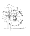
図8に示すように、先ず、支柱4の中心軸31と直交するとともに、仰角調整軸32を通過し、かつ、基準面(地面)33と平行になる平面を仰角調整中心平面34と定義する。次に、支柱4の中心軸31及び仰角調整中心平面34の交点35と、アンテナ中心軸36とを通過する平面をアンテナ中心平面37と定義する。
As shown in FIG. 8, first, a plane that is orthogonal to the
図11〜図13に示す従来のアンテナ装置では、仰角調整中心平面とアンテナ中心平面が重なるか、或いは、平行になるが、本実施の形態にかかるアンテナ装置1では、図6及び図8に示すように、仰角調整中心平面34とアンテナ中心平面37が斜めに交わり、両者の間に平面交差角度38を有する状態となる。
In the conventional antenna device shown in FIGS. 11 to 13, the elevation angle adjustment center plane and the antenna center plane are overlapped or parallel to each other, but the
次に、本発明にかかるアンテナ装置の第2の実施形態について、図9を参照しながら説明する。尚、この図において、図1〜図8と同一の構成要素については、同一符号を付し、その説明を省略する。 Next, a second embodiment of the antenna device according to the present invention will be described with reference to FIG. In this figure, the same components as those in FIGS. 1 to 8 are denoted by the same reference numerals, and the description thereof is omitted.
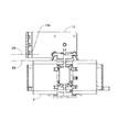
本実施の形態にかかるアンテナ装置40において、アンテナ2、収容ボックス3及びアンテナ取付金具5の構成は、図1〜図8に示すアンテナ装置1の場合と同様である。但し、本実施の形態のアンテナ装置40では、図9に示すように、アンテナ2の上下を反転させ、アンテナ接続部6において、第2の接続部6bを第1の接続部6aの下方に位置させる。
In the
その状態で、仰角調整金具12の長板部22に穿設された貫通孔24a〜24e(図4参照)のうちの中央に位置する貫通孔24cと、上部に位置する貫通孔24a、24bとの3個の貫通孔を使用し、仰角調整金具12とアンテナ2を連結する。
In that state, a through
上記連結構造により、連結部8の下方で仰角調整金具12とアンテナ接続部6を連結させ、ナット19b(仰角調整する際に操作を要する箇所の上端部)を、収容ボックス3の下端部よりも下方に位置させる。このため、第1の実施形態と同様の作用・効果を奏することが可能になる。
With the connection structure, the elevation
尚、上記の第1及び第2の実施形態においては、仰角調整金具12の長板部22に5個の貫通孔24a〜24eをX状に配列して穿設するが、貫通孔の数や配列は上記の態様に限られるものではない。例えば、6個の貫通孔を長方形状に配列して穿設し、それらのうちの4個を用いて仰角調整金具12のアンテナ2への接続を行うようにしてもよい。但し、この場合、貫通孔の数や配列の変更に合わせて、アンテナ接続部6の第2の接続部6bの形状、ねじ孔26a〜26c(図3参照)の数や位置も変更する必要がある。
In the first and second embodiments described above, the five through
次に、本発明にかかるアンテナ装置の第3の実施形態について、図10を参照しながら説明する。尚、この図において、図1〜図8と同一の構成要素については、同一符号を付し、その説明を省略する。 Next, a third embodiment of the antenna device according to the present invention will be described with reference to FIG. In this figure, the same components as those in FIGS. 1 to 8 are denoted by the same reference numerals, and the description thereof is omitted.
本実施の形態にかかるアンテナ装置50では、図10(a)、(b)に示すように、図1〜図8のアンテナ接続部6及び仰角調整金具12に代えて、これらを一体に形成した仰角調整機能付きアンテナ接続部51(以下、単に「アンテナ接続部51」という)を備える。
In the
上記アンテナ装置50においても、仰角調整する際に操作を要する箇所と収容ボックス3との高さを異ならせることができるため、第1の実施形態と同様の作用・効果を奏することができる。
Also in the
また、本実施の形態によれば、部品点数を削減することができ、さらには、図10(b)に示すように、接続作業が必要な箇所をアンテナ接続部51とクランプ11の受け金具15との間のみとすることができるため、アンテナ施工工事の際の手間を軽減することも可能になる。 In addition, according to the present embodiment, the number of parts can be reduced, and furthermore, as shown in FIG. Therefore, it is possible to reduce the labor for the antenna construction work.
尚、図10においては、仰角調整する際に操作を要する箇所を収容ボックス3の上方に位置させる場合のみを示しているが、第2の実施形態の場合と同様に、上下を反転させ、仰角調整する際に操作を要する箇所を収容ボックス3の下方に位置させることもできる。
Note that FIG. 10 shows only the case where the position that requires an operation when adjusting the elevation angle is positioned above the
1 アンテナ装置
2 アンテナ
2a 背面
3 収容ボックス
4 支柱
5 アンテナ取付金具
6 アンテナ接続部
6a 第1の接続部
6b 第2の接続部
8 連結部
9 接続板
10 一体型アンテナ
11 クランプ
12 仰角調整金具
14 押さえ金具
15 受け金具
15a 平坦面
16 ボルト
17 ナット
18(18a〜18d) ボルト
19(19a〜19d) ナット
20 貫通孔
21 短板部
22 長板部
23(23a〜23f) 貫通孔
24(24a〜24e) 貫通孔
25(25a〜25c) 取付ねじ
26(26a〜26c) ねじ孔
27 工具
28 仰角調整する際に操作を要する箇所の下端部
29 収容ボックスの上端部
31 支柱の中心軸
32 仰角調整軸
33 基準面
34 仰角調整中心平面
35 交点
36 アンテナ中心軸
37 アンテナ中心平面
38 平面交差角度
40 アンテナ装置
50 アンテナ装置
51 仰角調整機能付きアンテナ接続部
DESCRIPTION OF
Claims (8)
前記アンテナ取付金具が、前記支柱に締め付け固定されるクランプと、該クランプ及び前記アンテナを連結するとともに、該アンテナの仰角を調整するための仰角調整操作部を該クランプとの接続部に有する仰角調整金具とを備え、
前記仰角調整操作部が、前記収容部と異なる高さに位置することを特徴とするアンテナ装置。 An antenna, a receiving part that is mounted on the back surface of the antenna and accommodates electrical components for communication, and an antenna with the receiving part mounted thereon are connected to the support with the antenna protruding to the side of the support. An antenna device including an antenna mounting bracket to be fixed,
Elevation angle adjustment in which the antenna mounting bracket has an elevation angle adjustment operation unit for connecting the clamp and the antenna, and an elevation angle adjustment operation unit for adjusting the elevation angle of the antenna at a connection portion with the clamp. With metal fittings,
The antenna apparatus according to claim 1, wherein the elevation angle adjusting operation unit is located at a different height from the housing unit.
該アンテナ接続部は、連結部を通じて前記収容部が接続される第1の接続部と、該第1の接続部の上方に形成され、前記仰角調整金具が接続される第2の接続部とを備え、前記アンテナの背面に前記収容部を装着した状態で、前記第2の接続部が前記連結部の上端部よりも上方に位置することを特徴とする請求項2に記載のアンテナ装置。 Comprising an antenna connecting portion attached to the back of the antenna;
The antenna connecting portion includes a first connecting portion to which the housing portion is connected through a connecting portion, and a second connecting portion that is formed above the first connecting portion and to which the elevation angle adjusting bracket is connected. The antenna device according to claim 2, wherein the second connection portion is positioned above an upper end portion of the coupling portion in a state where the housing portion is mounted on a back surface of the antenna.
該アンテナ接続部は、連結部を通じて前記収容部が接続される第1の接続部と、該第1の接続部の下方に形成され、前記仰角調整金具が接続される第2の接続部とを備え、前記アンテナの背面に前記収容部を装着した状態で、前記第2の接続部が前記連結部の下端部よりも下方に位置することを特徴とする請求項4に記載のアンテナ装置。 Comprising an antenna connecting portion attached to the back of the antenna;
The antenna connection portion includes a first connection portion to which the housing portion is connected through a connecting portion, and a second connection portion that is formed below the first connection portion and to which the elevation angle adjusting bracket is connected. 5. The antenna device according to claim 4, wherein the second connection portion is positioned below a lower end portion of the coupling portion in a state where the housing portion is mounted on a back surface of the antenna.
前記アンテナ取付金具が、前記支柱に締め付け固定されるクランプと、該クランプ及び前記アンテナを連結するとともに、該アンテナの仰角を調整するための仰角調整操作部を該クランプとの接続部に有する仰角調整金具とを備え、
前記支柱の中心軸と直交しつつ、仰角調整軸を通過する平面を仰角調整中心平面と定義するとともに、該仰角調整中心平面及び前記支柱の中心軸の交点と前記アンテナの中心軸とを通過する平面をアンテナ中心平面と定義したときに、前記仰角調整中心平面と前記アンテナ中心平面が斜めに交差することを特徴とするアンテナ装置。 An antenna, a receiving part that is mounted on the back surface of the antenna and accommodates electrical components for communication, and an antenna with the receiving part mounted thereon are connected to the support with the antenna protruding to the side of the support. An antenna device including an antenna mounting bracket to be fixed,
Elevation angle adjustment in which the antenna mounting bracket has an elevation angle adjustment operation unit for connecting the clamp and the antenna, and an elevation angle adjustment operation unit for adjusting the elevation angle of the antenna at a connection portion with the clamp. With metal fittings,
A plane that passes through the elevation angle adjustment axis while being orthogonal to the center axis of the support column is defined as an elevation angle adjustment center plane, and passes through the intersection point of the elevation angle adjustment center plane and the center axis of the support column and the center axis of the antenna. An antenna device characterized in that, when a plane is defined as an antenna center plane, the elevation angle adjustment center plane and the antenna center plane intersect obliquely.
前記支柱に締め付け固定されるクランプと、該クランプ及び前記アンテナを連結するとともに、該アンテナの仰角を調整するための仰角調整操作部を該クランプとの接続部に有する仰角調整金具とを備え、
前記仰角調整操作部が、前記収容部と異なる高さに位置することを特徴とするアンテナ取付金具。 An antenna mounting bracket for fixing an antenna mounted on the back side with a housing portion containing electrical components for communication, to the column in a state where the antenna protrudes to the side of the column,
A clamp that is fastened and fixed to the support, and an elevation angle adjusting bracket that connects the clamp and the antenna and has an elevation angle adjustment operation unit for adjusting an elevation angle of the antenna at a connection portion with the clamp,
The antenna mounting bracket, wherein the elevation angle adjusting operation portion is located at a different height from the housing portion.
Priority Applications (1)
| Application Number | Priority Date | Filing Date | Title |
|---|---|---|---|
| JP2010252432A JP5818239B2 (en) | 2010-11-11 | 2010-11-11 | Antenna device and antenna mounting bracket |
Applications Claiming Priority (1)
| Application Number | Priority Date | Filing Date | Title |
|---|---|---|---|
| JP2010252432A JP5818239B2 (en) | 2010-11-11 | 2010-11-11 | Antenna device and antenna mounting bracket |
Publications (2)
| Publication Number | Publication Date |
|---|---|
| JP2012105107A true JP2012105107A (en) | 2012-05-31 |
| JP5818239B2 JP5818239B2 (en) | 2015-11-18 |
Family
ID=46394988
Family Applications (1)
| Application Number | Title | Priority Date | Filing Date |
|---|---|---|---|
| JP2010252432A Active JP5818239B2 (en) | 2010-11-11 | 2010-11-11 | Antenna device and antenna mounting bracket |
Country Status (1)
| Country | Link |
|---|---|
| JP (1) | JP5818239B2 (en) |
Cited By (6)
| Publication number | Priority date | Publication date | Assignee | Title |
|---|---|---|---|---|
| WO2015037167A1 (en) | 2013-09-11 | 2015-03-19 | 日本電気株式会社 | Container box for antenna device and electric device |
| KR101517774B1 (en) | 2013-07-15 | 2015-05-07 | 주식회사 굿텔 | Bracket for mounting antenna |
| CN107546459A (en) * | 2016-06-27 | 2018-01-05 | 泰兴市东盛电子器材厂 | A kind of whip antenna leaning device |
| CN109004363A (en) * | 2018-07-30 | 2018-12-14 | 佛山市富乐喜电子信息技术有限公司 | A kind of micro-strip flat plane antenna microwave remote sensor steering structure |
| CN110217406A (en) * | 2019-05-17 | 2019-09-10 | 陕西飞机工业(集团)有限公司 | A kind of antenna house test clamping device |
| WO2020076572A1 (en) * | 2018-10-12 | 2020-04-16 | Commscope Technologies Llc | Brackets for mounting antenna cables |
Citations (4)
| Publication number | Priority date | Publication date | Assignee | Title |
|---|---|---|---|---|
| JPH0520402U (en) * | 1991-07-10 | 1993-03-12 | 凸版印刷株式会社 | Planar antenna |
| JPH09326622A (en) * | 1996-06-04 | 1997-12-16 | Nec Corp | Antenna support structure |
| JP2002135017A (en) * | 2000-10-24 | 2002-05-10 | Toshiba Corp | Method and device for installing antenna |
| JP2003152409A (en) * | 2001-11-13 | 2003-05-23 | Matsushita Electric Ind Co Ltd | Antenna mount |
-
2010
- 2010-11-11 JP JP2010252432A patent/JP5818239B2/en active Active
Patent Citations (4)
| Publication number | Priority date | Publication date | Assignee | Title |
|---|---|---|---|---|
| JPH0520402U (en) * | 1991-07-10 | 1993-03-12 | 凸版印刷株式会社 | Planar antenna |
| JPH09326622A (en) * | 1996-06-04 | 1997-12-16 | Nec Corp | Antenna support structure |
| JP2002135017A (en) * | 2000-10-24 | 2002-05-10 | Toshiba Corp | Method and device for installing antenna |
| JP2003152409A (en) * | 2001-11-13 | 2003-05-23 | Matsushita Electric Ind Co Ltd | Antenna mount |
Cited By (12)
| Publication number | Priority date | Publication date | Assignee | Title |
|---|---|---|---|---|
| KR101517774B1 (en) | 2013-07-15 | 2015-05-07 | 주식회사 굿텔 | Bracket for mounting antenna |
| WO2015037167A1 (en) | 2013-09-11 | 2015-03-19 | 日本電気株式会社 | Container box for antenna device and electric device |
| US9685985B2 (en) | 2013-09-11 | 2017-06-20 | Nec Corporation | Antenna device and container box for electric device |
| CN107546459A (en) * | 2016-06-27 | 2018-01-05 | 泰兴市东盛电子器材厂 | A kind of whip antenna leaning device |
| CN107546459B (en) * | 2016-06-27 | 2024-03-19 | 泰兴市东盛电子器材厂 | Whip antenna lodging device |
| CN109004363A (en) * | 2018-07-30 | 2018-12-14 | 佛山市富乐喜电子信息技术有限公司 | A kind of micro-strip flat plane antenna microwave remote sensor steering structure |
| CN109004363B (en) * | 2018-07-30 | 2020-08-11 | 佛山市富乐喜电子信息技术有限公司 | Steering structure of micro-strip planar antenna microwave sensor |
| WO2020076572A1 (en) * | 2018-10-12 | 2020-04-16 | Commscope Technologies Llc | Brackets for mounting antenna cables |
| US11159006B2 (en) | 2018-10-12 | 2021-10-26 | Commscope Technologies Llc | Brackets for mounting antenna cables |
| US11621548B2 (en) | 2018-10-12 | 2023-04-04 | Commscope Technologies Llc | Brackets for mounting antenna cables |
| US11916366B2 (en) | 2018-10-12 | 2024-02-27 | Commscope Technologies Llc | Brackets for mounting antenna cables |
| CN110217406A (en) * | 2019-05-17 | 2019-09-10 | 陕西飞机工业(集团)有限公司 | A kind of antenna house test clamping device |
Also Published As
| Publication number | Publication date |
|---|---|
| JP5818239B2 (en) | 2015-11-18 |
Similar Documents
| Publication | Publication Date | Title |
|---|---|---|
| JP5818239B2 (en) | Antenna device and antenna mounting bracket | |
| JP5964470B1 (en) | Communication device and communication device mounting member | |
| JP3121915U (en) | Hybrid power generation system | |
| JP2006219823A (en) | Pipe supporting implement and pipe supporting device using it | |
| JP4488919B2 (en) | Signal lamp mounting bracket | |
| KR20170023714A (en) | Clamps for fixing cables | |
| JP2014240235A (en) | Fitting structure of control device and cantilever member used in fitting structure | |
| CN115189080A (en) | Clamping device and battery pack with same | |
| JP2011021413A (en) | Hold-down hardware | |
| CN212251478U (en) | Pipeline supporting device | |
| US11056762B2 (en) | Adjustable antenna mount | |
| JP5761012B2 (en) | Bracket and electronic equipment | |
| CN219177415U (en) | Display screen support of transport vehicle | |
| JP4570681B1 (en) | Mounting bracket | |
| JP4258844B2 (en) | Pole mounting attachment | |
| CN217194990U (en) | Turnover tool for assembling automobile chassis parts | |
| CN217227302U (en) | Vehicle-mounted reversible instrument board, vehicle instrument and truck | |
| JP3213684U (en) | Connection device | |
| JP4022170B2 (en) | Metal fittings for reinforcing bars and separators | |
| CN208855626U (en) | Electronic vacuum pump bracket and vehicle | |
| CN218468724U (en) | Support frame | |
| CN111457161A (en) | Pipeline supporting device | |
| CN207741909U (en) | A kind of sync response device for vibration test | |
| JP5323616B2 (en) | Position adjustment hardware for hole down hardware | |
| JP6747889B2 (en) | Mounting hardware |
Legal Events
| Date | Code | Title | Description |
|---|---|---|---|
| A621 | Written request for application examination |
Free format text: JAPANESE INTERMEDIATE CODE: A621 Effective date: 20131003 |
|
| A977 | Report on retrieval |
Free format text: JAPANESE INTERMEDIATE CODE: A971007 Effective date: 20140319 |
|
| A131 | Notification of reasons for refusal |
Free format text: JAPANESE INTERMEDIATE CODE: A131 Effective date: 20140625 |
|
| A521 | Written amendment |
Free format text: JAPANESE INTERMEDIATE CODE: A523 Effective date: 20140825 |
|
| A02 | Decision of refusal |
Free format text: JAPANESE INTERMEDIATE CODE: A02 Effective date: 20141210 |
|
| A61 | First payment of annual fees (during grant procedure) |
Free format text: JAPANESE INTERMEDIATE CODE: A61 Effective date: 20150924 |
|
| R150 | Certificate of patent or registration of utility model |
Ref document number: 5818239 Country of ref document: JP Free format text: JAPANESE INTERMEDIATE CODE: R150 |
|
| S111 | Request for change of ownership or part of ownership |
Free format text: JAPANESE INTERMEDIATE CODE: R313115 |
|
| R350 | Written notification of registration of transfer |
Free format text: JAPANESE INTERMEDIATE CODE: R350 |