JP2012104326A5 - - Google Patents
Download PDFInfo
- Publication number
- JP2012104326A5 JP2012104326A5 JP2010250899A JP2010250899A JP2012104326A5 JP 2012104326 A5 JP2012104326 A5 JP 2012104326A5 JP 2010250899 A JP2010250899 A JP 2010250899A JP 2010250899 A JP2010250899 A JP 2010250899A JP 2012104326 A5 JP2012104326 A5 JP 2012104326A5
- Authority
- JP
- Japan
- Prior art keywords
- light source
- light
- lens
- center line
- optical center
- Prior art date
- Legal status (The legal status is an assumption and is not a legal conclusion. Google has not performed a legal analysis and makes no representation as to the accuracy of the status listed.)
- Granted
Links
Images

Description
本発明は、発光ダイオードを含む半導体発光装置を光源とする車両用照明灯具に関する。 The present invention relates to a vehicular illumination lamp using a semiconductor light emitting device including a light emitting diode as a light source.
近年、半導体発光装置を光源とする車両用照明灯具のうち、レンズを用いて光源が発した光を屈折させて(反射面を用いることなく)所定の配光パターンを形成するものが知られている(例えば、特許文献1参照。)。 2. Description of the Related Art In recent years, among vehicular illumination lamps that use a semiconductor light emitting device as a light source, those that refract light emitted from a light source using a lens and form a predetermined light distribution pattern (without using a reflective surface) are known. (For example, refer to Patent Document 1).
しかしながら、上述のような従来の車両用照明灯具では、例えば下のような問題があった。すなわち、従来の車両用照明灯具では、図3のようにレンズの中心(またはその近傍)に光源の発光部の中心があるため、例えば図4のようにリムなど(エクステンションやハウジングである場合も含む)灯具の外形を形成するために必要な非透過性部材をレンズの外周の周囲に配置した場合に、その非透過性部材によって光が遮られてしまう(光束利用率が下がってしまう)という問題があった。 However, the conventional vehicular illumination lamp as described above has the following problems, for example. That is, in the conventional vehicular illumination lamp, since the center of the light emitting part of the light source is at the center of the lens (or in the vicinity thereof) as shown in FIG. When the non-transmissive member necessary for forming the outer shape of the lamp is arranged around the outer periphery of the lens, light is blocked by the non-transmissive member (the luminous flux utilization rate is reduced). There was a problem.
また、従来の車両用照明灯具では、上述のような位置に光源を配置するため、外部から光源が視認されるため、見栄えが優れないという問題があった。この問題は、半導体発光装置として広く用いられる疑似白色発光ダイオード(青色発光ダイオードの発光面に黄色蛍光体を設け、発光ダイオードからの青色光と蛍光体が励起されて生じる黄色光との混色で白色光を生成するもの)を使用した場合に、光源の不点灯時に蛍光体の黄色味が視認されてしまうため顕著であった。 Moreover, in the conventional vehicular illumination lamp, since the light source is arranged at the position as described above, the light source is visually recognized from the outside, and thus there is a problem that the appearance is not excellent. This problem is a pseudo white light emitting diode widely used as a semiconductor light emitting device (a yellow phosphor is provided on the light emitting surface of a blue light emitting diode, and the white color is a mixture of blue light from the light emitting diode and yellow light generated by exciting the phosphor) In the case of using a light generating material, the yellowishness of the phosphor is visually recognized when the light source is not turned on.
以上より、本発明は、半導体発光装置を光源とする車両用照明灯具において光源の光束を効率よく利用することを、その解決しようとする課題とする。
また、本発明は、上記車両用照明灯具において、特に光源の不点灯時の見栄えを改善することを、解決しようとすることを、他の課題とする。
In view of the above, an object of the present invention is to solve the problem of efficiently using a light beam of a light source in a vehicular illumination lamp using a semiconductor light emitting device as a light source.
Another object of the present invention is to solve the above-mentioned vehicular illumination lamp, in particular, to improve the appearance when the light source is not lit.
以上の課題に鑑み、本発明は以下の手段とした。
すなわち、本発明は、半導体発光装置からなる光源と、前記光源に対向し、前記光源が発した放射光を屈折させて所定の配光パターンを形成するレンズと、前記レンズの外周の周囲に設けた非透過性部材と、を備える車両用照明灯具であり、前記光源は、発光ダイオードであり、前記光源における発光部の中心を含むその近傍を通り前記光源正面に向かう前記光の放射方向に延伸する線を光源光学中心線としたとき、前記光源光学中心線が、前記レンズを通過するように配置されており、前記レンズは、前記光源に対向する側の内側表面及び前記内側表面と反対側の外側表面のいずれもが、前記光源側に向かって凹んだ凹曲面からなるとともに、前記光源から放射した光束を、前記光源光学中心線から照射方向に向かって略一方の側に広がる照射範囲の範囲に光を照射して所定距離離れた位置にある仮想スクリーンに所定配光パターンを形成するように形成されており、前記光源光学中心線が、当該レンズの正面視における外形両端からの距離的な中心線より外寄りに位置しており、前記車両用灯具の正面から視認したときに、前記レンズの中心位置から外れた位置に前記光源が視認されるとともに、前記非透過性部材が映りこみが視認可能とされている。
In view of the above problems, the present invention has the following means.
That is, the present invention includes a light source composed of a semiconductor light emitting device, facing the light source, a lens for forming a predetermined light distribution pattern refracts radiation beam the light source emitted, provided around the outer periphery of the lens A non-transparent member, and the light source is a light emitting diode, and extends in the light emitting direction toward the front of the light source through the vicinity including the center of the light emitting unit in the light source. The light source optical center line is disposed so as to pass through the lens, and the lens is disposed on the inner surface facing the light source and on the side opposite to the inner surface. Each of the outer surfaces of the light source has a concave curved surface that is recessed toward the light source side, and the light beam emitted from the light source spreads from the light source optical center line to the substantially one side toward the irradiation direction. Range of elevation range is formed so as to form a predetermined light distribution pattern to the virtual screen at a predetermined distance away by irradiating light to the light source optical center line, the outer ends of the front view of the lens The light source is visually recognized at a position deviating from the center position of the lens when viewed from the front of the vehicular lamp, and the non-transparent member. Is visible.
以上のように、本発明は、上述のような位置に光学中心を持つレンズを用いることにより、リムなど灯具の外形を形成するために必要な非透過性部材をレンズの外周の周囲に配置した場合に、そのリムなどによって光が遮られる(光束利用率が下がる)ことがない。
また、上述の構成より、本発明は、比較的外方より内部が視認しやすいレンズの中心位置に光源を配置しないため、外部からの光の屈折やリムのような外装部品の映り込みなどが生じやすく、その結果として光源が外部から視認されにくい。その結果として、本発明によれば、特に光源の不点灯時の見栄えを改善できる。
また、本発明は、前記光学中心が、当該レンズの外形端近傍にあってもよい。
このようにすれば、より外部から光源が視認されにくく更に光源の不点灯時の見栄えを改善できる。
As described above, according to the present invention, by using the lens having the optical center at the position as described above, the non-permeable member necessary for forming the outer shape of the lamp such as a rim is arranged around the outer periphery of the lens. In some cases, light is not blocked by the rim or the like (the luminous flux utilization rate is not lowered).
In addition, from the above-described configuration, the present invention does not place the light source at the center position of the lens that is relatively easy to visually recognize the inside from the outside. As a result, the light source is hardly visible from the outside. As a result, according to the present invention, it is possible to improve the appearance particularly when the light source is not turned on.
In the present invention, the optical center may be in the vicinity of the outer edge of the lens.
In this way, the light source is less visible from the outside, and the appearance when the light source is not turned on can be improved.
以上のように、本発明によれば、半導体発光装置を光源とする車両用照明灯具において光源の光束を効率よく利用するという優れた効果を奏する。
また、本発明は、上記車両用照明灯具において、特に光源の不点灯時の見栄えを改善するという、他の効果を奏する。
As described above, according to the present invention, there is an excellent effect of efficiently using the luminous flux of the light source in the vehicular illumination lamp using the semiconductor light emitting device as the light source.
In addition, the present invention has the other effect of improving the appearance of the above-described vehicular illumination lamp, particularly when the light source is not lit.
以下、本発明の一実施の形態に係る車両用照明灯具について説明する。
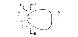
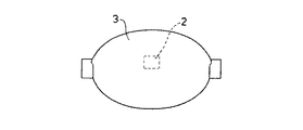
図1は、本実施の形態にかかる車両用照明灯具1の正面図である。
車両用照明灯具1は、例えば疑似白色発光ダイオードなどの半導体発光装置からなる光源2と、前記光源が発した光を屈折させて所定の配光パターンを形成するレンズ3とを備える。
Hereinafter, a vehicular illumination lamp according to an embodiment of the present invention will be described.
FIG. 1 is a front view of a
The
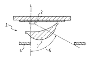
図2は、本実施形態に係る車両用照明灯具の横(A−A)断面図、図3は、本実施形態に係る車両用照明灯具の縦(B−B)断面図である。 FIG. 2 is a horizontal (AA) cross-sectional view of the vehicular illumination lamp according to the present embodiment, and FIG. 3 is a vertical (BB) cross-sectional view of the vehicular illumination lamp according to the present embodiment.
車両用照明灯具1において、レンズ3は、光源2における発光部の中心(中心を含むその近傍であってもよい)を通り光の放射方向に延伸する線L(レンズの光軸であり灯具の光軸)を光源光学中心線Lとすると、光源光学中心線Lが、レンズ3の正面視における外形両端からの距離的な中心線より外寄りに位置するように設置されている。
In the
つまり、レンズ3は、この光源光学中心線Lから照射方向(車両に取り付けた場合には車両前方)に向かって略一方の側に広がる照射範囲Eの範囲に光を照射して所定距離離れた位置にある仮想スクリーンに所定配光パターンを形成するように、光源2からレンズ3への入射光とレンズ3から外部への出射光との関係が設定されている。
In other words, the
以上のように、車両用照明灯具1は、上述のような位置に光源光学中心線Lを持つレンズ3を用いることにより、リム4など灯具の外形を形成するために必要な非透過性部材をレンズ3の外周の周囲に配置した場合に、照射範囲Eがそのリム4などによって遮られる(光束利用率が下がる)ことがない。
As described above, the
車両用照明灯具1(特にフォグランプのような補助前照灯)において、その取り付け位置によってはバンパーなどの車両の外装部品(不図示)が灯具の照射方向側方寄りに存在することがあり、このような場合に本実施形態のような構成を取ることは有効である。 In the vehicular illumination lamp 1 (especially an auxiliary headlamp such as a fog lamp), depending on the mounting position, an exterior part of the vehicle such as a bumper (not shown) may be present on the side of the lamp in the irradiation direction. In such a case, it is effective to adopt the configuration of the present embodiment.
また、上述の構成を有する車両用照明灯具1は、図6のような、従来の車両用照明灯具と異なり比較的外方より内部が視認しやすいレンズ3の中心位置に光源を配置しないため、外部からの光の屈折やリム4のような外装部品の映り込みなどが生じやすく、その結果として光源2(の蛍光体)が外部から視認されにくい。その結果として、車両用照明灯具1によれば、特に光源の不点灯時の見栄えを改善できる。
In addition, the
また、車両用照明灯具1は、光源光学中心線Lが、当該レンズ3の外形端近傍にあってもよい。このようにすれば、より外部から光源2が視認されにくく更に光源の不点灯時の見栄えを改善できる。
In the
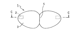
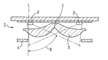
以下に、上記構成の車両用照明灯具1を基本構成とする応用例について説明する。図4は、本実施形態の応用例に係る車両用照明灯具の正面図である。又は、図5は、本実施形態の応用例に係る車両用照明灯具の横(C−C)断面図である。
Below, the application example which makes the
本応用例では、上記実施形態で説明した車両用照明灯具1の光源2とレンズ3とを二組備える。ここで、レンズ3は、横断面図において二組のレンズ3の外側表面(光源2が配置されていない側)で互いの外周が接する外周接続部5を構成するように配置されている。
In this application example, two sets of the
このような応用例の車両用照明灯具では、一つの光源2とレンズ3との組み合わせによる照射範囲Eの偏りを互いに補完しつつリム4によって光が遮られることがないため、光束利用率を高めることができる。
In the vehicular illumination lamp of such an application example, the light is not blocked by the rim 4 while complementing the deviation of the irradiation range E due to the combination of the
1… 車両用照明灯具
2… 光源
3… レンズ
4… リム
5… 外周接続部
DESCRIPTION OF
5 ... Peripheral connection
Claims (2)
前記光源に対向し、前記光源が発した放射光を屈折させて所定の配光パターンを形成するレンズと、
前記レンズの外周の周囲に設けた非透過性部材と、を備える車両用照明灯具であり、
前記光源は、発光ダイオードであり、前記光源における発光部の中心を含むその近傍を通り前記光源正面に向かう前記光の放射方向に延伸する線を光源光学中心線としたとき、前記光源光学中心線が、前記レンズを通過するように配置されており、
前記レンズは、前記光源に対向する側の内側表面及び前記内側表面と反対側の外側表面のいずれもが、前記光源側に向かって凹んだ凹曲面からなるとともに、
前記光源から放射した光束を、前記光源光学中心線から照射方向に向かって略一方の側に広がる照射範囲の範囲に光を照射して所定距離離れた位置にある仮想スクリーンに所定配光パターンを形成するように形成されており、
前記光源光学中心線が、当該レンズの正面視における外形両端からの距離的な中心線より外寄りに位置しており、
前記車両用灯具の正面から視認したときに、前記レンズの中心位置から外れた位置に前記光源が視認されるとともに、前記非透過性部材が映りこみが視認可能とされている、
ことを特徴とする車両用照明灯具。 A light source comprising a semiconductor light emitting device;
A lens for forming a predetermined light distribution pattern to face the light source, is refracted radiation beam the light source emitted by,
An impermeable member provided around the outer periphery of the lens, and a vehicular illumination lamp,
The light source is a light emitting diode, and the light source optical center line is a light source optical center line when a line extending in the radiation direction toward the front of the light source through the vicinity including the center of the light emitting unit in the light source is a light source optical center line. Is arranged to pass through the lens,
The lens has a concave curved surface in which both the inner surface facing the light source and the outer surface opposite to the inner surface are recessed toward the light source side,
A predetermined light distribution pattern is applied to a virtual screen located at a predetermined distance by irradiating a light beam emitted from the light source to a range of an irradiation range extending substantially on one side from the light source optical center line toward an irradiation direction. Formed to form,
The light source optical center line is located outside the distance center line from both ends of the outer shape in front view of the lens ,
When viewed from the front of the vehicular lamp, the light source is viewed at a position deviating from the center position of the lens, and reflection of the non-transmissive member is visible.
A vehicular illumination lamp characterized by the above.
前記各組のレンズが、各レンズの外側表面において互いの外周が接する外周接続部を構成するように配置されており、
第1の組の光源の光源光学中心線は、前記外周接続部から離れた第1の組のレンズの外形端に位置し、
第2の組の光源の光源光学中心線は、前記外周接続部から離れた第2の組のレンズの外形端に位置し、
前記第1の組の前記照射範囲は、前記第1の組の光源から放射した光束を、第1の組の前記光源光学中心線から照射方向に向かって第2の組の側に広がる照射範囲であり、
前記第2の組の前記照射範囲は、前記第2の組の光源から放射した光束を、第2の組の前記光源光学中心線から照射方向に向かって第1の組の側に広がる照射範囲であり、
前記第1の組の照射範囲の偏りと、前記第2の組の照射範囲の偏りが互いに補完するものとされている、
ことを特徴とする、請求項1に記載の車両用照明灯具。 Two sets of the light source and the lens are provided,
Each set of lenses is arranged so as to constitute an outer peripheral connection portion where the outer peripheries contact each other on the outer surface of each lens,
The light source optical center line of the first set of light sources is located at the outer edge of the first set of lenses away from the outer peripheral connection,
The light source optical center line of the second set of light sources is located at the outer edge of the second set of lenses away from the outer peripheral connection,
The irradiation range of the first set is an irradiation range in which a light beam emitted from the light source of the first set spreads toward the second set toward the irradiation direction from the light source optical center line of the first set. And
The irradiation range of the second set is an irradiation range in which light beams emitted from the second set of light sources spread toward the first set from the light source optical center line of the second set toward the irradiation direction. And
The bias of the irradiation range of the first set and the bias of the irradiation range of the second set complement each other,
The vehicular illumination lamp according to claim 1, wherein:
Priority Applications (1)
| Application Number | Priority Date | Filing Date | Title |
|---|---|---|---|
| JP2010250899A JP5588832B2 (en) | 2010-11-09 | 2010-11-09 | Lighting fixtures for vehicles |
Applications Claiming Priority (1)
| Application Number | Priority Date | Filing Date | Title |
|---|---|---|---|
| JP2010250899A JP5588832B2 (en) | 2010-11-09 | 2010-11-09 | Lighting fixtures for vehicles |
Publications (3)
| Publication Number | Publication Date |
|---|---|
| JP2012104326A JP2012104326A (en) | 2012-05-31 |
| JP2012104326A5 true JP2012104326A5 (en) | 2013-11-28 |
| JP5588832B2 JP5588832B2 (en) | 2014-09-10 |
Family
ID=46394492
Family Applications (1)
| Application Number | Title | Priority Date | Filing Date |
|---|---|---|---|
| JP2010250899A Active JP5588832B2 (en) | 2010-11-09 | 2010-11-09 | Lighting fixtures for vehicles |
Country Status (1)
| Country | Link |
|---|---|
| JP (1) | JP5588832B2 (en) |
Families Citing this family (3)
| Publication number | Priority date | Publication date | Assignee | Title |
|---|---|---|---|---|
| JP6496976B2 (en) * | 2014-02-19 | 2019-04-10 | 市光工業株式会社 | Vehicle headlamp |
| JP6801344B2 (en) * | 2016-09-29 | 2020-12-16 | 市光工業株式会社 | Vehicle lighting |
| JP6956605B2 (en) * | 2017-11-20 | 2021-11-02 | スタンレー電気株式会社 | Automotive fog lights |
Family Cites Families (7)
| Publication number | Priority date | Publication date | Assignee | Title |
|---|---|---|---|---|
| JP2626199B2 (en) * | 1990-07-25 | 1997-07-02 | 日産自動車株式会社 | Vehicle discharge lamp headlamp |
| JP4131178B2 (en) * | 2003-02-28 | 2008-08-13 | 豊田合成株式会社 | Light emitting device |
| JP4191651B2 (en) * | 2004-06-24 | 2008-12-03 | 株式会社小糸製作所 | Vehicle lighting |
| JP4684952B2 (en) * | 2006-06-16 | 2011-05-18 | 株式会社小糸製作所 | Vehicle headlamp lamp unit |
| JP2008218184A (en) * | 2007-03-05 | 2008-09-18 | Toshiba Lighting & Technology Corp | Light source unit |
| JP5255301B2 (en) * | 2008-03-12 | 2013-08-07 | 株式会社小糸製作所 | Vehicle headlamp device |
| JP5157883B2 (en) * | 2008-12-25 | 2013-03-06 | 市光工業株式会社 | Vehicle headlamp |
-
2010
- 2010-11-09 JP JP2010250899A patent/JP5588832B2/en active Active
Similar Documents
| Publication | Publication Date | Title |
|---|---|---|
| JP4391870B2 (en) | Lighting fixtures for vehicles | |
| JP4926771B2 (en) | Vehicle lamp unit | |
| JP4339143B2 (en) | Vehicle lamp unit | |
| JP5519400B2 (en) | Lighting fixtures for vehicles | |
| JP5397186B2 (en) | Vehicle lighting | |
| JP2012169050A (en) | Lamp for vehicle | |
| JP2015149158A (en) | Vehicular lighting fixture | |
| JP2006156301A (en) | Vehicle headlight unit | |
| JP2017212037A (en) | Vehicular headlight | |
| JP6317087B2 (en) | Vehicle lighting | |
| JP4926642B2 (en) | Lighting fixtures for vehicles | |
| US20130063961A1 (en) | Vehicle lamp | |
| WO2014148029A1 (en) | Vehicle lamp fitting | |
| JP4339153B2 (en) | Vehicle lamp unit | |
| JP5460201B2 (en) | Vehicle headlamp | |
| JP4536483B2 (en) | Lighting fixtures for vehicles | |
| JP2021153024A5 (en) | ||
| JP2012160356A (en) | Vehicular lamp | |
| JP5588832B2 (en) | Lighting fixtures for vehicles | |
| JP2012104326A5 (en) | ||
| JP2011108412A (en) | Vehicle light | |
| JP5412324B2 (en) | Lighting fixtures for vehicles | |
| JP6518459B2 (en) | Vehicle lamp | |
| JP2015146270A (en) | Vehicular lighting fixture | |
| JP2018045838A (en) | Light emitting module and vehicular lighting fixture |