JP2012103192A - Light wave distance meter - Google Patents
Light wave distance meter Download PDFInfo
- Publication number
- JP2012103192A JP2012103192A JP2010253651A JP2010253651A JP2012103192A JP 2012103192 A JP2012103192 A JP 2012103192A JP 2010253651 A JP2010253651 A JP 2010253651A JP 2010253651 A JP2010253651 A JP 2010253651A JP 2012103192 A JP2012103192 A JP 2012103192A
- Authority
- JP
- Japan
- Prior art keywords
- distance measurement
- filter
- distance
- signal
- filter position
- Prior art date
- Legal status (The legal status is an assumption and is not a legal conclusion. Google has not performed a legal analysis and makes no representation as to the accuracy of the status listed.)
- Granted
Links
Images


Abstract
Description
本発明は、位相差方式の光波距離計に関するものであって、特に、測距光路間に受光光量を調節する可変式受光濃度フィルタが配置された光波距離計に関する。 The present invention relates to a phase difference type light wave distance meter, and more particularly to a light wave distance meter in which a variable light receiving density filter that adjusts the amount of received light is disposed between distance measuring optical paths.
位相差方式の光波距離計には、例えば下記特許文献1,2に開示されたものが知られている。この種の光波距離計は図5に示すように、発振器1で出力された信号が符号2〜4を経て強度変調されて発光素子11から光として送出される。係る光は、測定地点に配置したプリズム等の目標反射物22に反射させて得られる測距光と、参照光路26へ射出して得た参照光となって、択一的に受光素子30で受光されてそれぞれ測距信号と参照信号となり、該受光信号が符号32〜40を経てアナログ信号からデジタルデータへ変換されて、演算処理部であるCPU50で測距光と参照光のデジタル信号の位相差が算出されて、目標反射物22までの直線距離(測距値)が測定されるものである。
For example, those disclosed in the following
目標反射物22と受光素子30の間には、連続的な濃度勾配を有し、演算処理部50で制御される可変式受光濃度フィルタ25が配置されていて、可変濃度フィルタ25は、測距信号の一部を短時間でサンプリングした測距信号振幅がその測定に適した所定範囲よりも大きればフィルタを閉じる(フィルタ濃度を濃くする)方向に、逆に前記振幅が小さければフィルタを開ける(フィルタ濃度を薄める)方向にフィルタ位置を段階的に調節する。係るフィルタ位置調節が1回以上行われ、可変濃度フィルタ25が初期フィルタ位置からその測距に適したフィルタ位置に設定されると、目標反射物22までの直線距離の測定(測距)が行われる。
A variable light
しかし、例えば光波距離計から目標反射物22までの距離が遠いと、大気の揺らぎの影響を大きく受けて測距光路が曲げられ、測距光の測距信号が減衰し、可変濃度フィルタ25は大気の揺らぎが小さいときよりも開いた位置に決定される傾向がある。このため、フィルタ位置の調節が困難となって時間が掛かり、所望の測距仕様時間を越えてしまう場合があった。
However, for example, if the distance from the optical wave distance meter to the
これに対して、可変濃度フィルタ25の初期のフィルタ位置を初めから開いた位置にセットすると、大気の揺らぎが大きい時には最適なフィルタ位置に早く設定される可能性は高くなるが、逆に大気の揺らぎが小さい時や目標反射物22までの距離が近い時には測距信号レベルが測距可能範囲を超えてしまい、係る信号は測距に用いることができない(棄却される)ため、測距信号の信号棄却率が高くなる。
On the other hand, if the initial filter position of the
また、測距信号レベルが測距可能範囲を超過しないようにするためには、可変濃度フィルタ25を初めから閉じた位置にセットすることも考えられるが、過度にフィルタが閉じられてしまうため、測距信号の信号雑音比が上がり、やはり測距精度が悪くなるという問題が生じた。
In order to prevent the distance measurement signal level from exceeding the distance measurement possible range, the
本願発明は、かかる問題点に鑑みて為されたものであり、その第1の目的は、可変濃度フィルタをすばやく最適なフィルタ位置にすることで、フィルタ位置設定が遅延することのない光波距離計を提供することにある。第2の目的は、測距ごとに最適なフィルタ位置とすることで、測距値算出に有効な測距信号のサンプル数を増やして測距の測定回数を減らし、その結果、測距精度が下がることなく測距時間も短縮された光波距離計を提供することにある。 The present invention has been made in view of such problems, and a first object of the invention is to quickly set the variable density filter to the optimum filter position, so that the filter position setting is not delayed. Is to provide. The second purpose is to set the optimum filter position for each distance measurement, thereby increasing the number of distance measurement signal samples effective for distance value calculation and reducing the number of distance measurement times. As a result, the distance measurement accuracy is improved. An object of the present invention is to provide a lightwave distance meter with a reduced distance measurement time without lowering.
請求項1の光波距離計は、複数の変調周波数で変調された光を送出する光送出手段と、該光送出手段の光を測定地点に配置した目標反射物または参照光路のうち選択された一方に送出する光路切換手段と、前記目標反射物で反射された測距光の測距光路間に配置され、連続的な濃度勾配を有する受光光量調整用の可変式受光濃度フィルタと、前記測距光または前記参照光路を通過した参照光を受光して測距信号または参照信号を出力する受光手段と、前記測距信号と参照信号の位相差によって目標反射物までの直線距離である測距値を算出する演算処理部と、を備えた光波距離計において、測距ごとに、少なくとも算出された測距値、前記可変濃度フィルタのフィルタ位置、及び受光光量が測距可能範囲を超えた前記測距信号のサンプル数と測距に使うサンプル数との比を表す信号棄却率、の測定データを記憶する記憶手段を設け、前記演算処理部に、前記測距信号の少なくとも1周期分を含むサンプリングデータから短時間測距信号振幅およびサンプル測距値を算出する短時間測定手段と、前記記憶手段に記憶されている過去の測距値を参照し、前記短時間測定手段で得られたサンプル測距値との差異が1m以下の測距値データが無いときは通常の測距を開始し、差異が1m以下の測距値データがあるときは、該測距値データの中から可変濃度フィルタが最も閉じられたフィルタ位置を参照し、該フィルタ位置に前記可変濃度フィルタを設定するとともに、該フィルタ位置での信号棄却率を前記記憶手段から参照し、該信号棄却率が0%であるときはそのフィルタ位置で測距を開始するが、該信号棄却率が0%でないときはそのフィルタ位置よりもフィルタ濃度を0超〜1%濃くして測距を開始するフィルタ位置調節手段と、前記フィルタ位置調節手段による前記可変濃度フィルタの位置調整後に、測距を行い、その信号棄却率を算出する測距及び棄却率算出手段と、前記測距及び棄却率算出手段後に、算出された測距値、前記フィルタ位置調節手段で得られた可変濃度フィルタのフィルタ位置、及び前記測距及び棄却率算出手段で算出された測距信号の信号棄却率、の測定データを前記記憶手段に格納させる測定データ記憶指示手段を設けた。 The lightwave distance meter according to claim 1 is one selected from a light transmission means for transmitting light modulated at a plurality of modulation frequencies, and a target reflector or a reference light path in which the light of the light transmission means is arranged at a measurement point. An optical path switching means for transmitting to the optical path; a variable light reception density filter for adjusting the amount of received light having a continuous density gradient, disposed between the distance measurement optical paths of the distance measurement light reflected by the target reflector; and the distance measurement A light receiving means that receives light or reference light that has passed through the reference light path and outputs a distance measurement signal or a reference signal; and a distance measurement value that is a linear distance to a target reflector by a phase difference between the distance measurement signal and the reference signal An optical distance meter comprising: an arithmetic processing unit for calculating at least a distance value calculated for each distance measurement, a filter position of the variable density filter, and a light receiving light amount exceeding the range capable of distance measurement. The number of distance signal samples and A storage means for storing measurement data of a signal rejection rate that represents a ratio to the number of samples used for the distance is provided, and the arithmetic processing unit is provided with a short-time ranging signal from sampling data including at least one period of the ranging signal. The difference between the short-time measurement means for calculating the amplitude and the sample distance measurement value and the sample distance measurement value obtained by the short-time measurement means with reference to the past distance measurement value stored in the storage means is 1 m. When the following distance measurement data is not available, normal distance measurement is started. When there is distance measurement data with a difference of 1 m or less, the filter position where the variable density filter is most closed among the distance measurement data. The variable density filter is set at the filter position, and the signal rejection rate at the filter position is referenced from the storage means. When the signal rejection rate is 0%, ranging is performed at the filter position. Open However, when the signal rejection rate is not 0%, filter position adjusting means for starting distance measurement by making the filter density higher than 0 to 1% higher than the filter position, and the variable density filter by the filter position adjusting means After the position adjustment, the distance is measured and the signal rejection rate is calculated, and the signal rejection rate is calculated by the distance measurement and rejection rate calculation means. After the distance measurement and rejection rate calculation means, the calculated distance value is obtained by the filter position adjustment means. Measurement data storage instructing means for storing the measurement data of the filter position of the obtained variable density filter and the signal rejection rate of the distance measurement signal calculated by the distance measurement and rejection rate calculating means is provided in the storage means.
(作用)一般的に、可変濃度フィルタのフィルタ位置は、大気の揺らぎの影響を受けるほど大気の揺らぎが小さい時よりも開いた位置(フィルタ濃度が薄い位置)に決まる傾向にあり、位置の調節も困難となる。 (Function) In general, the position of the variable density filter tends to be determined to be an open position (a position where the filter density is low) than when the atmospheric fluctuation is small enough to be affected by the atmospheric fluctuation. It will also be difficult.
しかし、過去の測定における測距値及び可変濃度フィルタのフィルタ位置の測定データを記憶手段に記憶しておき、短時間測定手段で得られたサンプル測距値と近い値(差異が1m以下)の測距値を過去の測定データから参照し、その中で最も閉じられたフィルタ位置を採用すれば、その直線距離の測定(測距)において最も大気の揺らぎの影響を受けていない最良のフィルタ位置で測定を行うことができるとともに、大気の揺らぎに影響されることなく最適なフィルタ位置をすばやく決めることができる。 However, the distance measurement value in the past measurement and the measurement data of the filter position of the variable density filter are stored in the storage means, and a value close to the sample distance measurement value obtained by the short-time measurement means (the difference is 1 m or less). When the distance measurement value is referred to from past measurement data and the most closed filter position is adopted, the best filter position that is not affected by atmospheric fluctuation in the measurement of the linear distance (distance measurement) Measurement can be performed at the same time, and the optimum filter position can be quickly determined without being affected by atmospheric fluctuations.
さらに、過去の測定における測距信号の信号棄却率の測定データも記憶しておけば、その信号棄却率が0%でない限り測距信号レベルが測距可能範囲を超える場合があるということなので、信号棄却率が0%で無い場合には、前記最良フィルタ位置からさらに可変濃度フィルタを若干量(0超〜1%)閉めることで、フィルタを閉めすぎることなく、測距可能範囲を超える信号をさらに減らせるので、より適したフィルタ位置で測定を行うことが可能となる。そして、係る調節を含めても、数回の調節でフィルタ位置が決定されるため、フィルタ位置調節に要する時間が長引くことはない。 Furthermore, if the measurement data of the signal rejection rate of the ranging signal in the past measurement is also stored, the ranging signal level may exceed the distance measurement range unless the signal rejection rate is 0%. If the signal rejection rate is not 0%, close the variable density filter by a small amount (above 0 to 1%) from the best filter position, so that the signal exceeding the range can be measured without closing the filter too much. Since it can be further reduced, it is possible to perform measurement at a more suitable filter position. Even when such adjustment is included, the filter position is determined by several adjustments, so that the time required for the filter position adjustment is not prolonged.
また、これにより、比較する過去の測定データが増えるほど(測距を行えば行うほど)、その測距に最適なフィルタ位置が学習されていくこととなる。 As a result, as the past measurement data to be compared increases (as the distance is measured), the optimum filter position for the distance measurement is learned.
さらに、フィルタ位置が最適となる分、測距手段において測距値算出に有効な測距信号のサンプルが数多く得られる(測距信号の信号棄却率が下がる)ので、略全てのサンプルデータを測距値算出に用いることができる。このため、従来の測距精度を保ちながらも測距回数を減らすことができるので、結果的に、測距に要する時間も短縮することができる。 In addition, since the filter position is optimal, the ranging means can obtain many ranging signal samples that are effective in calculating the ranging value (the signal rejection rate of the ranging signal is reduced), so that almost all sample data can be measured. It can be used for distance value calculation. For this reason, the number of times of distance measurement can be reduced while maintaining the conventional distance measurement accuracy, and as a result, the time required for distance measurement can also be shortened.
請求項2は、請求項1の光波距離計において、前記演算処理部に、今回の測距値と前記記憶手段に記憶されている測距値の差異が1m以下のもの同士の可変濃度フィルタのフィルタ位置を比較して、その中で前記可変濃度フィルタが最も閉じられたフィルタ位置を有する測定データ以外を削除する記憶データ削除手段を設けた。 According to a second aspect of the present invention, in the light wave distance meter according to the first aspect, the arithmetic processing unit includes a variable density filter having a difference between the current distance measurement value and the distance measurement value stored in the storage means of 1 m or less. A stored data deleting means for comparing the filter positions and deleting data other than the measurement data having the filter position where the variable density filter is most closed is provided.
(作用)記憶手段に記憶されている過去の測定データのうち、測距値の値が近いもの(差異が1m以下)のなかで、可変濃度フィルタが最も閉じられたフィルタ位置データを有する測定データがその測距で最も大気の揺らぎの影響を受けなかった最良の測定データである。よって、係る最良の測定データ一組(測距値、可変濃度フィルタのフィルタ位置、信号棄却率)のみを残しそれ以外を削除することで、記憶手段の容量を効率良く空けられる。 (Operation) Among the past measurement data stored in the storage means, the measurement data having the filter position data in which the variable density filter is most closed among the ones having a close distance value (difference is 1 m or less) Is the best measurement data that was not affected by the fluctuation of the atmosphere at the distance measurement. Therefore, by leaving only one set of the best measurement data (ranging value, filter position of variable density filter, signal rejection rate) and deleting others, the capacity of the storage means can be efficiently emptied.
請求項1の光波距離計によれば、フィルタ位置設定時間が遅延することなく測距時間も短縮することができるので、全体の測距仕様時間が従来よりも大幅に短縮され、作業効率が格段に向上する。 According to the lightwave distance meter of the first aspect, the distance measurement time can be shortened without delaying the filter position setting time, so that the entire distance measurement specification time is significantly shortened compared with the conventional one, and the working efficiency is remarkably improved. To improve.
略同じ直線距離を測定するユーザにとっては、より早く最適なフィルタ位置が学習されるので、使い勝手が向上する。 For users who measure substantially the same straight line distance, the optimum filter position is learned earlier, so the usability is improved.
請求項2の光波距離計によれば、記憶手段の許容容量オーバーに伴う不具合が生じない。 According to the lightwave distance meter of the second aspect, there is no problem associated with the allowable capacity exceeding of the storage means.
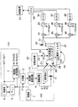
次に、図1に基づいて光波距離計の最適な実施形態を説明する。図1は、本願発明に係る光波距離計のブロック図である。実施例の光波距離計は、以下に示す光送出手段100、光路切換手段102、受光手段(受光素子30)、ローカル信号送出手段101、演算処理部(CPU50)、及び記憶手段(記憶装置51)等を構成要素に含む。
Next, an optimal embodiment of the optical wave distance meter will be described with reference to FIG. FIG. 1 is a block diagram of an optical distance meter according to the present invention. The lightwave distance meter of the embodiment includes a
発振器1、分周器2、周波数重畳回路3,駆動回路4、負荷抵抗8、及び発光素子11は、図1に示すように順に接続されて、光送出手段100を構成する。
The oscillator 1, the
発振器1は、所定の周波数を有する基準信号F1を発生させる。分周器2は、信号F1を分周して異なる周波数を有する信号F2,F3を発生させる。信号F1,F2,F3は、周波数重畳回路3によって重畳化される。電圧供給を受ける駆動回路4は、重畳化された信号(F1,F2,F3)に基づく交流信号によって発光素子11を駆動する。発光素子11は、一定の抵抗値を有する負荷抵抗8を介して直流電源でも駆動され、重畳化された信号(F1,F2,F3)の振幅で強度変調した光を送出させる。
The oscillator 1 generates a reference signal F1 having a predetermined frequency. The
一方、PLL(Phase Locked Loop)5、ローカル信号発振器6、周波数生成回路7は、ローカル信号送出手段101を構成する。PLL5は、発振器1に接続され、ローカル信号発振器6は、双方向の信号線によってPLL5と接続される。周波数生成回路7は、発振器1とローカル信号発振器6にそれぞれ接続される。またローカル信号発振器6は、後述する周波数変換機32に接続され、周波数生成回路7は、後述する周波数変換器(35,38)に接続されている。
On the other hand, a PLL (Phase Locked Loop) 5, a
ローカル信号発振器6は、PLL5を介して発振器1から基準信号F1を受けることにより、信号F1よりも微小値Δf1だけ周波数のずれた周波数信号F1+Δf1を周波数変換機32に出力する。周波数生成回路7は、発振器1から信号F1を受け、更にローカル信号発振器6から周波数信号F1+Δf1を受ける。そして、周波数生成回路7は、まず基準信号F1を信号F2,F3に分周すると共に、周波数信号F1+Δf1に基づいて、信号F2,F3よりも更に微小値Δf2、Δf3だけ周波数のずれた周波数信号F2+Δf2とF3+Δf3をそれぞれ出力する。周波数信号(F2+Δf2,F3+Δf3)は、それぞれ周波数変換器(35,38)に入力される。
The
発光素子11から送出された光は、ビームスプリッタ20及び切換シャッター28からなる光路切換手段102によって択一的に出射される。即ち、ビームスプリッタ20で測距光路21方向と参照光路26方向に2つに分けられ、切換シャッター28を切り換えることにより、該シャッター28に遮光されていない方の光路に送出される。
The light transmitted from the
切換シャッター28によって参照光路26側が遮光されることにより、測距光路21へ送出した光は、測定地点に配置したプリズム等の目標反射物22によって測距光路23に反射される。該反射された光(以降は、測距光という)は、受光光学24(集光レンズ等)で集光され、可変濃度フィルタ25で光量調節を受けたあと受光素子30(光受光手段)によって受光される。
Since the reference
可変濃度フィルタ25は、薄い円板状の透明体の受光光量調節手段であって、円周方向に光量減衰率が0%から99%まで連続的にフィルタ濃度が濃くなるように形成されている。これにより、円周方向の一端から円周方向の他端まで漸次光量の絞り効果が大きくなっていて、フィルタ濃度を濃くする方向に回転(フィルタを閉じる)またはフィルタ濃度を薄める方向に回転(フィルタを開ける)されて位置調節されることで、段階的に濃度調節される。なお、可変濃度フィルタ25の濃度変化は、直線的に変化しても、又二次曲線的に変化しても、或いは指数的に変化しても、角度変化と濃度変化の対応関係があれば良い。係るフィルタ位置調節は、後述するCPU50で制御されるアクチュエータ52(図示せず)等の駆動により円板が回転されることで行われる。
The
一方、切換シャッター28を切り換えて測距光路21側が遮光されることにより、参照光路26へ送出した光(以降は、参照光という)は、開閉式の所定の光量減衰率の濃度フィルタ27によって一定の光量調節を受けたあと受光素子30によって受光される。
On the other hand, by switching the switching
受光素子30には増幅器31が接続され、信号(F1,F2,F3)毎に周波数変換機(32,35,38)、低域フィルタ(33,36,39)、ADコンバータ(34,37,40)が接続されている。ADコンバータ(34,37,40)はそれぞれCPU50に接続され、CPU50には記憶装置51が接続されている。また、CPU50は図示しないアクチュエータ52を介して可変濃度フィルタ25にも接続されている。
An
受光素子30で受光された測距光と参照光は、それぞれ電気信号(測距信号,参照信号)として出力される。
The distance measuring light and the reference light received by the
測距信号,参照信号はそれぞれ増幅器31で増幅されたあと、F1,F2,F3を示す信号毎に周波数変換機(32,35,38)にそれぞれ入力される。
The distance measurement signal and the reference signal are respectively amplified by the
周波数変換器(32,35,38)は、測距信号または参照信号として入力された信号(F1,F2,F3)を、ローカル信号送出手段101側の周波数信号(F1+Δf1,F2+Δf2,F3+Δf3)と乗算して、より周波数帯が低く扱い易い中間周波信号(Δf1,Δf2,Δf3)を発生する。中間周波信号(Δf1,Δf2,Δf3)は、帯域フィルタ(33,36,39)によって高周波成分がノイズとして除去されて、ADコンバータ(34,37,40)に送られる。ここで、測距信号または参照信号は、電気信号からデジタル信号に変換されてCPU50に入力される。
The frequency converter (32, 35, 38) converts the signals (F1, F2, F3) input as ranging signals or reference signals into frequency signals (F1 + Δf1, F2 + Δf2, F3 + Δf3) on the local signal transmission means 101 side. To generate intermediate frequency signals (Δf1, Δf2, Δf3) that have a lower frequency band and are easy to handle. The intermediate frequency signals (Δf1, Δf2, Δf3) are sent to the AD converters (34, 37, 40) after the high frequency components are removed as noises by the bandpass filters (33, 36, 39). Here, the distance measurement signal or the reference signal is converted from an electrical signal to a digital signal and input to the
演算処理部であるCPU50では、入力された測距信号と参照信号のデジタル信号からそれぞれの信号振幅と位相情報が解析され、測距光と参照光の位相差により、光波距離計内部で発生する誤差が補正されて、光波距離計から目標反射物22までの直線距離(測距値)が算出される。
The
また、CPU50では、係る測距値算出の過程において、後述する短時間測定手段、フィルタ位置調節手段、測距及び棄却率算出手段、及び測定データ記憶指示手段を行う。また、記憶装置51に対して後述する記憶データ削除手段を適宜行う。
The
CPU50に接続された記憶手段である記憶装置51には、CPU50における測距値算出に必要な種々のプログラムが格納されているとともに、算出された測距値、フィルタ位置調節手段で得られた可変濃度フィルタ25のフィルタ位置、及び測距可能範囲を超えた測距信号のサンプル数を表す信号棄却率、の各測定データが格納される。
The storage device 51, which is a storage means connected to the
以下、図2,図3に基づいて光波距離計の性質を説明し、図4のフローチャート図に基づいて実施例に係る光波距離計の測距の手順及び本願発明の特徴的部分である可変濃度フィルタ25の調節手段について詳細に説明する。
Hereinafter, the properties of the lightwave distance meter will be described with reference to FIGS. 2 and 3, and the distance measurement procedure of the lightwave distance meter according to the embodiment and the variable density which is a characteristic part of the present invention will be described with reference to the flowchart of FIG. The adjusting means of the
一般的に、光波距離計には、仕様に応じて適正光量が定められている。具体的には、受光素子30を経て得られた測距信号レベルがCPU50で解析できる適正範囲(測距可能範囲)に収まるように、測距信号の最大振幅値と最小振幅値の閾値が予め設定され、記憶装置51に記憶されている。
Generally, an appropriate amount of light is determined for a lightwave distance meter according to specifications. Specifically, the threshold value of the maximum amplitude value and the minimum amplitude value of the distance measurement signal is set in advance so that the distance measurement signal level obtained through the
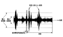
図2は、従来の光波距離計で遠距離測距した場合のADコンバータ(34,37,40)でサンプリングされた測距信号波形の一例を示す図であって、横軸は時間を、縦軸は測距信号の信号振幅を示す。受光素子30から得られた測距信号が規定の最大振幅値を超える信号は、CPU50にて測距算出に用いることができないデータとなって棄却される。測距時間内に得られた測距信号の全サンプル数のうち最大振幅値を超える信号の数の割合を信号棄却率という。
FIG. 2 is a diagram showing an example of a ranging signal waveform sampled by an AD converter (34, 37, 40) when a long-range distance measurement is performed with a conventional optical wave rangefinder, where the horizontal axis indicates time, and the vertical axis indicates time. The axis indicates the signal amplitude of the ranging signal. A signal in which the distance measurement signal obtained from the
信号棄却率が小さくなるように、CPU50は、短時間で得られた測距信号の数周期分のサンプリングデータから、短時間測距信号振幅を算出し、記憶装置51の設定値と比較して差を測定し、測距信号が閾値内に入るようにアクチュエータ52に制御信号を発することで、短時間測距信号振幅が最大振幅値よりも大きればフィルタを閉じる(フィルタ濃度を濃くする)方向に、逆に小さければフィルタを開ける(フィルタ濃度を薄める)方向にフィルタ位置を段階的に調節する。係る調節が1回以上行われて、可変濃度フィルタ25がその直線距離の測定に適したフィルタ位置に設定されると、測距が開始される。
In order to reduce the signal rejection rate, the
しかし、一般的に目標反射物22までの直線距離と可変濃度フィルタ25のフィルタ位置の関係は図3のようになる。図3は、光波距離計と測定対象物22との直線距離と可変濃度フィルタ25のフィルタ位置との関係を示す図であって、大気の揺らぎの影響を説明する図である。横軸は光波距離計から目標反射物22までの直線距離を、縦軸は可変濃度フィルタ25のフィルタ位置、即ちフィルタの濃度を表している。図3より、
(i)光波距離計から目標反射物22までの距離が近い場合(近距離測距の場合)は、可変濃度フィルタ25は閉じる方向に制御される。
(ii)測距時の大気の揺らぎが大きいと、測距光路が曲げられ、測距光の測距信号が減衰し、可変濃度フィルタ25は大気の揺らぎが小さいときよりも開いた位置に決定される。
(iii)光波距離計から目標反射物22までの距離が遠い(遠距離測距)ほど、大気の揺らぎの影響を大きく受ける。
However, the relationship between the linear distance to the
(I) When the distance from the light wave rangefinder to the
(Ii) If the atmospheric fluctuation at the time of distance measurement is large, the distance measuring optical path is bent, the distance measurement signal of the distance measuring light is attenuated, and the
(iii) The greater the distance from the light wave rangefinder to the target reflector 22 (far-distance measurement), the greater the influence of atmospheric fluctuations.
ことが分かる。このため、特に遠距離測距の場合には、大気の揺らぎの影響を大きく受けて、可変濃度フィルタ25のフィルタ位置の調節が困難となる。
I understand that. For this reason, particularly in the case of long-distance ranging, it is difficult to adjust the filter position of the
これに対して、可変濃度フィルタ25の初期フィルタ位置を初めから開いた位置にセットすれば、大気の揺らぎが大きい時には最適なフィルタ位置に早く設定される可能性は高くなるが、逆に大気の揺らぎが小さい時や目標反射物22までの距離が近い時には測距信号レベルが測距可能範囲を超えてしまい、信号棄却率が高くなる。また、測距信号レベルが測距可能範囲を超過しないように可変濃度フィルタ25の初期フィルタ位置を初めから閉じた位置にセットすると、過度にフィルタが閉じられてしまうため、測距信号の信号雑音比が上がりやはり測距精度が悪くなるという問題が生じる。
On the other hand, if the initial filter position of the
ここで、測距時の大気の揺らぎが大きい状況であっても、過去にその距離で大気揺らぎが小さかった時の可変濃度フィルタ25のフィルタ位置データがあれば、そのフィルタ位置が、その距離にとって適したフィルタ位置である。そして、その測距値において、今までで最も大気の揺らぎの影響を受けなかったフィルタ位置とは、最も閉じられたフィルタ位置であることが分かる。
Here, even if the atmospheric fluctuation at the time of distance measurement is large, if there is filter position data of the
即ち、過去の測距値、フィルタ位置の測定データを一組として記憶しておけば、同じような(近い値の)測距値同士を比較して、その中で最も閉じられた最良のフィルタ位置を採用することができる。 That is, if the past distance measurement value and the measurement data of the filter position are stored as a set, the same (near value) distance measurement values are compared, and the best filter that is most closed among them is compared. Position can be employed.
さらに、過去の測定における測距信号の信号棄却率の測定データも併せて記憶しておけば、その信号棄却率が0%でない限り、測距信号レベルが測距可能範囲を超える場合があるということである。そこで、過去の最良フィルタ位置からさらに可変濃度フィルタ25を若干量閉めることで、過度にフィルタを閉めることなく、測距可能範囲を超える測距信号を減らすことができるので、より適したフィルタ位置で測定することが可能となる。
Furthermore, if the measurement data of the signal rejection rate of the distance measurement signal in the past measurement is also stored, the distance measurement signal level may exceed the distance measurement range unless the signal rejection rate is 0%. That is. Therefore, by further closing the
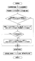
以下、図4のフローチャート図に基づいて、実施例に係る光波距離計の測距の手順を詳細に説明する。 Hereinafter, based on the flowchart of FIG. 4, the procedure of distance measurement of the lightwave distance meter according to the embodiment will be described in detail.
測距を開始すると、前記符号100、101、102を経て受光素子30で受光された測距信号または参照信号は、符号31〜40を経てCPUに入力され、CPU50で短時間測定手段が開始される。
When the distance measurement is started, the distance measurement signal or reference signal received by the
短時間測定手段では、短時間で得られた測距信号の数周期分のサンプリングデータから従来通り短時間測距信号振幅を算出するが、これに加えて、サンプリングデータから測距値も算出する(以下、これをサンプル測距値という)。 The short-time measuring means calculates the short-range ranging signal amplitude as usual from the sampling data for several cycles of the ranging signal obtained in a short time. In addition to this, the ranging value is also calculated from the sampling data. (Hereinafter, this is referred to as a sample ranging value).
次に、従来通り、短時間測距信号振幅値と記憶装置51に記憶されている最大振幅値、最小振幅値とが比較されて、その差が測定され、測距信号が閾値内に入るように制御信号が出され、アクチュエータ52により可変濃度フィルタ25が短時間測定から最適とされる位置(初期フィルタ位置)に設定される。
Next, as in the past, the short-time ranging signal amplitude value is compared with the maximum amplitude value and the minimum amplitude value stored in the storage device 51, the difference is measured, and the ranging signal falls within the threshold value. Then, the control signal is output, and the actuator 52 sets the
次に、フィルタ位置調節手段が開始される。 Next, the filter position adjusting means is started.
フィルタ位置調節手段では、始めに、短時間測定手段で得られたサンプル測距値と記憶装置51に記憶されている過去の測距値とを照らし合わせ、サンプル測距値との差異が1m以内の近い値の測距値データが記憶装置51に記憶されているかを探索する。ここで、近い値か否かの判断を差異1m以内とするのは、十分信頼できる精度が得られることと記憶装置51の記憶容量のバランスの観点からである。なお、記憶装置51の記憶容量を10倍にして差異を0.1m以内とすれば、より精度が上がるため好ましい。 In the filter position adjustment means, first, the sample distance measurement value obtained by the short time measurement means is compared with the past distance measurement value stored in the storage device 51, and the difference from the sample distance measurement value is within 1 m. A search is made as to whether distance measurement value data having a close value is stored in the storage device 51. Here, the reason for determining whether or not the values are close is within a difference of 1 m from the viewpoint of obtaining sufficiently reliable accuracy and the balance of the storage capacity of the storage device 51. Note that it is preferable to increase the storage capacity of the storage device 51 by 10 times so that the difference is within 0.1 m because accuracy is further improved.
記憶装置51内に差異が1m以内の測距値データが無いときは、今回のサンプル測距値の距離は初めて測定する直線距離であるので、初期フィルタ位置のまま、測距及び棄却率算出手段に移る。 When there is no distance measurement data having a difference of 1 m or less in the storage device 51, the distance of the current sample distance measurement is a linear distance measured for the first time. Move on.
一方、記憶装置51内に差異が1m以内の測距値データがあるときは、今回のサンプル測距値の距離は2回目以上の測定となるので記憶装置51内に過去の測定データが存在する。そこで、まず、差異が1m以内の測距値データの中から可変濃度フィルタ25が最も閉じているフィルタ位置を判定し、これを二次フィルタ位置として可変濃度フィルタ25を再設定する。次に、二次フィルタ位置に採用された測定における信号棄却率を記憶装置51から参照する。
On the other hand, when there is distance measurement data having a difference of 1 m or less in the storage device 51, the distance of the current sample distance measurement value is the second or more measurement, and thus past measurement data exists in the storage device 51. . Therefore, first, the filter position at which the
二次フィルタ位置に採用された測定の信号棄却率が0%であるときは、その距離に対して二次フィルタ位置を採用すれば、測距信号レベルが測距可能範囲を超えることは無いということを意味するので、二次フィルタ位置がその測距における最適なフィルタ位置である。よって、二次フィルタ位置のまま測距及び棄却率算出手段に移る。 When the signal rejection rate of the measurement adopted for the secondary filter position is 0%, if the secondary filter position is adopted for that distance, the distance measurement signal level will not exceed the distance measurement possible range. Therefore, the secondary filter position is the optimum filter position for the distance measurement. Therefore, the distance measurement and rejection rate calculation means are moved to the secondary filter position.
逆に、信号棄却率が0%でないときは二次フィルタ位置を採用してもまだ測距可能範囲を超える信号があることを意味する。よって、より適したフィルタ位置となるように、フィルタ濃度をさらに若干量、具体的には1%(より好ましくは0.1%)閉め、フィルタ濃度を一段濃くした位置(三次フィルタ位置)に再調節して測距及び棄却率算出手段に移る。 Conversely, when the signal rejection rate is not 0%, it means that there is still a signal exceeding the distance measurement possible range even if the secondary filter position is adopted. Therefore, the filter density is closed by a little more, specifically 1% (more preferably 0.1%), so that a more suitable filter position is obtained, and the filter density is further increased to a position (third-order filter position). Adjust and move to ranging and rejection rate calculation means.
これにより、二次フィルタ位置よりも一段光量が減衰され、得られる測距信号の信号振幅が小さくなるため、信号棄却率をより0%に近づけることができる。また、その距離に対して可変濃度フィルタ25が過度に濃くなることもない。
As a result, the first-stage light intensity is attenuated from the secondary filter position, and the signal amplitude of the obtained distance measurement signal is reduced, so that the signal rejection rate can be made closer to 0%. Further, the
フィルタ位置調節手段によって場合に応じて可変濃度フィルタを調整すると、測距及び棄却率算出手段にて、測距を行い、得られた測距信号と参照信号の位相差から目標対象物22までの測距値を算出し、得られた測距信号から係る測距における信号棄却率を算出する。ここで、係る測距で得られた測距信号は、従来の光波距離計で得られる測距信号よりも信号棄却率が非常に低いので、従来のサンプル数よりも測定回数が少なくて済む。 When the variable density filter is adjusted according to the case by the filter position adjusting means, the distance measurement and the rejection rate calculating means measure the distance, and from the phase difference between the obtained distance measurement signal and the reference signal to the target object 22 A distance measurement value is calculated, and a signal rejection rate in the distance measurement is calculated from the obtained distance measurement signal. Here, the distance measurement signal obtained by such distance measurement has a much lower signal rejection rate than the distance measurement signal obtained by the conventional lightwave distance meter, so that the number of times of measurement is less than the number of conventional samples.
最後に、測定データ記憶指示手段にて、算出された測距値、フィルタ位置調節手段で得られた可変濃度フィルタ25のフィルタ位置、及び算出された測距信号の信号棄却率を記憶手段51に格納して、測距が終了する。
Finally, in the measurement data storage instruction means, the calculated distance measurement value, the filter position of the
以上により、短時間測定手段で得られたサンプル測距値を利用して、これと近い値がある場合には、過去の測距値の中から最も閉じられたフィルタ位置を参照することで、大気の揺らぎに影響されることなく、最大でも3回の調節ですばやく最適なフィルタ位置を決めることができるので、フィルタ位置調節のための時間が長引くことはない。 By using the sample distance measurement value obtained by the short-time measurement means as described above, if there is a value close to this, by referring to the most closed filter position from the past distance measurement value, Since the optimum filter position can be quickly determined by three adjustments at the maximum without being affected by atmospheric fluctuations, the time for adjusting the filter position is not prolonged.
また、測距信号の信号棄却率を利用して、信号棄却率が0%でなければフィルタ位置をさらに再設定するため、測定を行えば行うほど信号棄却率が0%に近づいて、最適なフィルタ位置が学習されていく。 Further, if the signal rejection rate of the distance measurement signal is used and the signal rejection rate is not 0%, the filter position is further reset. Therefore, the more the measurement is performed, the closer the signal rejection rate becomes to 0%. The filter position is learned.
さらに、フィルタ位置が最適となる分、測距可能範囲内(閾値内)の測距信号が増えるので、測距で得られた略全てのサンプルデータを測距値算出に用いることができる。このため、従来の測距精度を保ちながらも測距回数(測距信号のサンプル数)を減らすことができるので、本願発明の光波距離計では、測距に要する時間も短縮することができる。 Further, since the distance measurement signals within the distance measurement possible range (within the threshold value) are increased by the optimum filter position, almost all sample data obtained by distance measurement can be used for distance measurement value calculation. For this reason, since the number of times of distance measurement (number of samples of the distance measurement signal) can be reduced while maintaining the conventional distance measurement accuracy, the time required for distance measurement can be shortened in the lightwave distance meter of the present invention.
また、いずれの直線距離の測定においても、比較する過去の測定データが増えるほど(測距を行えば行うほど)、大気の揺らぎの影響が小さくなるように可変濃度フィルタが徐々に閉じられていくので、大気の揺らぎの影響を受けなくなっていく(図3破線矢印)。 In any linear distance measurement, the variable density filter is gradually closed to reduce the influence of atmospheric fluctuations as the past measurement data to be compared increases (the more distance measurement is performed). Therefore, it is no longer affected by atmospheric fluctuations (dashed arrows in FIG. 3).
よって、フィルタ位置設定時間が遅延することはなく、さらに測距時間も短縮することができるので、全体の測距仕様時間が従来よりも大幅に短縮され、ユーザーにとっては作業効率が格段に向上する。 Therefore, the filter position setting time is not delayed, and the distance measurement time can be further shortened, so that the overall distance measurement specification time is significantly shortened compared to the conventional method, and the work efficiency is greatly improved for the user. .
また、略同じ直線距離を測距するユーザにとっては、より早く最適なフィルタ位置が学習されるので、測距仕様時間が極めて短くなり、使い勝手が向上する。 In addition, for users who measure the distance of substantially the same linear distance, the optimum filter position is learned earlier, so that the distance measurement specification time is extremely shortened and the usability is improved.
また、記憶手段51の記憶容量には限度があるため、測距ごとに測定データが蓄積されていくと、容量不足による動作遅延やフリーズ等の不具合が生じる恐れがある。そこで、CPU50は、記憶データ削除手段で、適宜不要な測定データを削除する。
In addition, since the storage capacity of the storage unit 51 is limited, if measurement data is accumulated for each distance measurement, there is a possibility that problems such as operation delay and freeze due to insufficient capacity may occur. Therefore, the
過去の測定データのうち、今回の測距値と値が近いもののなかで、最も閉じられた可変濃度フィルタ25のデータを有する測定データが、その測距値で最も大気の揺らぎの影響を受けなかった最良の測定データであるので、これ以外の測定データは不要である。
Among the past measurement data, the measurement data having the data of the most closed
そこで、記憶データ削除手段では、今回の測距値と容量記憶装置51に記憶されている過去の測距値の差異が1m以下のもの同士の可変濃度フィルタ25のフィルタ位置を比較して、その中で可変濃度フィルタ25が最も閉じられたフィルタ位置を有する一組の測定データ(測距値、可変濃度フィルタ25のフィルタ位置、信号棄却率)以外の測定データを、例えば測距終了のタイミングで削除する。
Therefore, the stored data deleting means compares the filter positions of the variable density filters 25 whose difference between the current distance measurement value and the past distance measurement value stored in the capacity storage device 51 is 1 m or less. Among them, measurement data other than a set of measurement data (ranging value, filter position of the
これにより、記憶装置51手段の容量が効率良く空くので、許容容量オーバーに伴う不具合は生じない。 As a result, the capacity of the storage device 51 is efficiently emptied, so that there is no problem associated with exceeding the allowable capacity.
11 発光素子
22 目標反射物
21、23 測距光路
25 可変濃度フィルタ
26 参照光路
30 受光素子(受光手段)
50 CPU(演算処理部)
51 記憶装置(記憶手段)
100 光送出手段
102 光路切換手段
DESCRIPTION OF
50 CPU (arithmetic processing unit)
51 Storage device (storage means)
100 Optical transmission means 102 Optical path switching means
Claims (2)
前記目標反射物で反射された測距光の測距光路間に配置され、連続的な濃度勾配を有する受光光量調整用の可変式受光濃度フィルタと、
前記測距光または前記参照光路を通過した参照光を受光して測距信号または参照信号を出力する受光手段と、
前記測距信号と参照信号の位相差によって目標反射物までの直線距離である測距値を算出する演算処理部と、を備えた光波距離計において
測距ごとに、少なくとも算出された測距値、前記可変濃度フィルタのフィルタ位置、及び受光光量が測距可能範囲を超えた前記測距信号のサンプル数と測距に用いるサンプル数との比を表す信号棄却率、の測定データを記憶する記憶手段を設け、
前記演算処理部に、
前記測距信号の少なくとも1周期分を含むサンプリングデータから短時間測距信号振幅およびサンプル測距値を算出する短時間測定手段と、
前記記憶手段に記憶されている過去の測距値を参照し、前記短時間測定手段で得られたサンプル測距値との差異が1m以下の測距値データが無いときは通常の測距を開始し、差異が1m以下の測距値データがあるときは、該測距値データの中から可変濃度フィルタが最も閉じられたフィルタ位置を参照し、該フィルタ位置に前記可変濃度フィルタを設定するとともに、該フィルタ位置での信号棄却率を前記記憶手段から参照し、該信号棄却率が0%であるときはそのフィルタ位置で測距を開始するが、該信号棄却率が0%でないときはそのフィルタ位置よりもフィルタ濃度を0超〜1%濃くして測距を開始するフィルタ位置調節手段と、
前記フィルタ位置調節手段による前記可変濃度フィルタの位置調整後に、測距を行い、その信号棄却率を算出する測距及び棄却率算出手段と、
前記測距及び棄却率算出手段後に、算出された測距値、前記フィルタ位置調節手段で得られた可変濃度フィルタのフィルタ位置、及び前記測距及び棄却率算出手段で算出された測距信号の信号棄却率、の測定データを前記記憶手段に格納させる測定データ記憶指示手段が設けられたことを特徴とする光波距離計。 A light sending means for sending light modulated at a plurality of modulation frequencies; a light path switching means for sending the light of the light sending means to a selected one of a target reflector or a reference light path arranged at a measurement point;
A variable light reception density filter for adjusting the amount of received light having a continuous density gradient, disposed between the distance measurement optical paths of the distance measurement light reflected by the target reflector;
A light receiving means for receiving the distance measuring light or the reference light that has passed through the reference light path and outputting a distance measuring signal or a reference signal;
A calculation unit that calculates a distance value, which is a linear distance to the target reflector, based on a phase difference between the distance measurement signal and the reference signal; and a distance value calculated at least for each distance measurement in the optical distance meter A memory for storing measurement data of a filter position of the variable density filter and a signal rejection rate representing a ratio between the number of samples of the ranging signal and the number of samples used for ranging in which the amount of received light exceeds the range capable of ranging Providing means,
In the arithmetic processing unit,
A short-time measuring means for calculating a short-range ranging signal amplitude and a sample ranging value from sampling data including at least one period of the ranging signal;
With reference to the past distance measurement values stored in the storage means, if there is no distance measurement data whose difference from the sample distance measurement value obtained by the short-time measurement means is 1 m or less, normal distance measurement is performed. When there is distance measurement data having a difference of 1 m or less, the variable density filter is referred to the most closed filter position in the distance measurement data, and the variable density filter is set at the filter position. At the same time, the signal rejection rate at the filter position is referred from the storage means, and when the signal rejection rate is 0%, ranging starts at the filter position, but when the signal rejection rate is not 0% Filter position adjusting means for starting distance measurement by setting the filter density to be more than 0 to 1% higher than the filter position;
Ranging after the position adjustment of the variable density filter by the filter position adjusting means, ranging to calculate the signal rejection rate and the rejection rate calculation means,
After the distance measurement and rejection rate calculation means, the calculated distance measurement value, the filter position of the variable density filter obtained by the filter position adjustment means, and the distance measurement signal calculated by the distance measurement and rejection rate calculation means An optical distance meter characterized by comprising measurement data storage instruction means for storing measurement data of a signal rejection rate in the storage means.
Priority Applications (1)
| Application Number | Priority Date | Filing Date | Title |
|---|---|---|---|
| JP2010253651A JP5610575B2 (en) | 2010-11-12 | 2010-11-12 | Light wave distance meter |
Applications Claiming Priority (1)
| Application Number | Priority Date | Filing Date | Title |
|---|---|---|---|
| JP2010253651A JP5610575B2 (en) | 2010-11-12 | 2010-11-12 | Light wave distance meter |
Publications (3)
| Publication Number | Publication Date |
|---|---|
| JP2012103192A true JP2012103192A (en) | 2012-05-31 |
| JP2012103192A5 JP2012103192A5 (en) | 2014-05-29 |
| JP5610575B2 JP5610575B2 (en) | 2014-10-22 |
Family
ID=46393756
Family Applications (1)
| Application Number | Title | Priority Date | Filing Date |
|---|---|---|---|
| JP2010253651A Expired - Fee Related JP5610575B2 (en) | 2010-11-12 | 2010-11-12 | Light wave distance meter |
Country Status (1)
| Country | Link |
|---|---|
| JP (1) | JP5610575B2 (en) |
Cited By (1)
| Publication number | Priority date | Publication date | Assignee | Title |
|---|---|---|---|---|
| JP2019174228A (en) * | 2018-03-28 | 2019-10-10 | 株式会社トプコン | Light wave distance meter and surveying device |
Citations (9)
| Publication number | Priority date | Publication date | Assignee | Title |
|---|---|---|---|---|
| JPH04350584A (en) * | 1991-05-28 | 1992-12-04 | Sokkia Co Ltd | Light wave range finder |
| JPH0798373A (en) * | 1993-09-28 | 1995-04-11 | Nec Corp | Laser radar device |
| JPH08262138A (en) * | 1995-03-24 | 1996-10-11 | Asahi Optical Co Ltd | Instrument for measuring distance by light wave and light quantity control method therefor |
| JPH09236662A (en) * | 1996-02-29 | 1997-09-09 | Ushikata Shokai:Kk | Electronic distance meter |
| JPH11230740A (en) * | 1998-02-12 | 1999-08-27 | Topcon Corp | Distance measurement device |
| JP2001349943A (en) * | 2000-06-06 | 2001-12-21 | Hitachi Ltd | Laser range finder, laser range finding method, and measuring device |
| JP2003255046A (en) * | 2002-03-04 | 2003-09-10 | Nikon Geotecs Co Ltd | Distance measuring equipment and method |
| JP2008209162A (en) * | 2007-02-23 | 2008-09-11 | Matsushita Electric Works Ltd | Range image sensor |
| JP2010107212A (en) * | 2008-10-28 | 2010-05-13 | Panasonic Electric Works Co Ltd | Distance measuring device |
-
2010
- 2010-11-12 JP JP2010253651A patent/JP5610575B2/en not_active Expired - Fee Related
Patent Citations (9)
| Publication number | Priority date | Publication date | Assignee | Title |
|---|---|---|---|---|
| JPH04350584A (en) * | 1991-05-28 | 1992-12-04 | Sokkia Co Ltd | Light wave range finder |
| JPH0798373A (en) * | 1993-09-28 | 1995-04-11 | Nec Corp | Laser radar device |
| JPH08262138A (en) * | 1995-03-24 | 1996-10-11 | Asahi Optical Co Ltd | Instrument for measuring distance by light wave and light quantity control method therefor |
| JPH09236662A (en) * | 1996-02-29 | 1997-09-09 | Ushikata Shokai:Kk | Electronic distance meter |
| JPH11230740A (en) * | 1998-02-12 | 1999-08-27 | Topcon Corp | Distance measurement device |
| JP2001349943A (en) * | 2000-06-06 | 2001-12-21 | Hitachi Ltd | Laser range finder, laser range finding method, and measuring device |
| JP2003255046A (en) * | 2002-03-04 | 2003-09-10 | Nikon Geotecs Co Ltd | Distance measuring equipment and method |
| JP2008209162A (en) * | 2007-02-23 | 2008-09-11 | Matsushita Electric Works Ltd | Range image sensor |
| JP2010107212A (en) * | 2008-10-28 | 2010-05-13 | Panasonic Electric Works Co Ltd | Distance measuring device |
Cited By (2)
| Publication number | Priority date | Publication date | Assignee | Title |
|---|---|---|---|---|
| JP2019174228A (en) * | 2018-03-28 | 2019-10-10 | 株式会社トプコン | Light wave distance meter and surveying device |
| JP7082892B2 (en) | 2018-03-28 | 2022-06-09 | 株式会社トプコン | Laser rangefinder and surveying device |
Also Published As
| Publication number | Publication date |
|---|---|
| JP5610575B2 (en) | 2014-10-22 |
Similar Documents
| Publication | Publication Date | Title |
|---|---|---|
| JP4828167B2 (en) | Distance measuring apparatus and method | |
| US7339655B2 (en) | Electric optical distance wavelength meter | |
| CN101261182B (en) | High reflectivity measurement method based on frequency selective optical feedback cavity ringdown spectroscopy | |
| JP5178761B2 (en) | FMCW signal generation circuit and radar device | |
| CN101261181B (en) | Device for measuring high reflectivity | |
| JPS633269B2 (en) | ||
| CN104236537A (en) | Light source intensity noise suppression digital double closed-loop method based on intensity modulator | |
| JP5610575B2 (en) | Light wave distance meter | |
| US4639129A (en) | Method of measuring distance between two observation points | |
| JP2006329797A (en) | Light wave range finder | |
| US20040051926A1 (en) | Photoelectronic mixing device (pmd) system | |
| JP5670829B2 (en) | Light wave distance meter | |
| JP2018044853A (en) | Laser emission device, control method and program | |
| JP5665286B2 (en) | Light wave distance meter | |
| CN109596565A (en) | It is a kind of to realize the device and method for receiving light intensity self-stabilization based on laser array | |
| JP4002199B2 (en) | Light wave distance meter | |
| CN116804746A (en) | Optical wave distance meter | |
| CN109743022A (en) | A method of improving crystal oscillator aging drift rate | |
| JP7082892B2 (en) | Laser rangefinder and surveying device | |
| CN115308715A (en) | Method and system for sparse modulation wind-measuring radar | |
| JP6213568B2 (en) | Biological information measuring device | |
| JP5730094B2 (en) | Light wave distance meter | |
| JPWO2013014761A1 (en) | Lightwave ranging device | |
| RU2312368C2 (en) | Method of measuring quality factor of resonator | |
| RU2610514C2 (en) | Laser phased range finder |
Legal Events
| Date | Code | Title | Description |
|---|---|---|---|
| A621 | Written request for application examination |
Free format text: JAPANESE INTERMEDIATE CODE: A621 Effective date: 20130905 |
|
| A977 | Report on retrieval |
Free format text: JAPANESE INTERMEDIATE CODE: A971007 Effective date: 20140411 |
|
| A521 | Written amendment |
Free format text: JAPANESE INTERMEDIATE CODE: A523 Effective date: 20140411 |
|
| A131 | Notification of reasons for refusal |
Free format text: JAPANESE INTERMEDIATE CODE: A131 Effective date: 20140520 |
|
| A521 | Written amendment |
Free format text: JAPANESE INTERMEDIATE CODE: A523 Effective date: 20140530 |
|
| TRDD | Decision of grant or rejection written | ||
| A01 | Written decision to grant a patent or to grant a registration (utility model) |
Free format text: JAPANESE INTERMEDIATE CODE: A01 Effective date: 20140827 |
|
| A61 | First payment of annual fees (during grant procedure) |
Free format text: JAPANESE INTERMEDIATE CODE: A61 Effective date: 20140829 |
|
| R150 | Certificate of patent or registration of utility model |
Ref document number: 5610575 Country of ref document: JP Free format text: JAPANESE INTERMEDIATE CODE: R150 |
|
| LAPS | Cancellation because of no payment of annual fees |