JP2012103003A - Torque sensor - Google Patents
Torque sensor Download PDFInfo
- Publication number
- JP2012103003A JP2012103003A JP2010247387A JP2010247387A JP2012103003A JP 2012103003 A JP2012103003 A JP 2012103003A JP 2010247387 A JP2010247387 A JP 2010247387A JP 2010247387 A JP2010247387 A JP 2010247387A JP 2012103003 A JP2012103003 A JP 2012103003A
- Authority
- JP
- Japan
- Prior art keywords
- voltage
- signal
- output
- coil
- torque detection
- Prior art date
- Legal status (The legal status is an assumption and is not a legal conclusion. Google has not performed a legal analysis and makes no representation as to the accuracy of the status listed.)
- Granted
Links
Images


Landscapes
- Power Steering Mechanism (AREA)
Abstract
【課題】簡素な構成でありながら、温度ドリフトの補償性能にも優れ、故障診断機能も具備したトルクセンサを提供する。
【解決手段】所定の励磁用交流信号を直流接続された2つのコイル11、12に印加し、該2つのコイルから生じる1つのコイル出力交流信号を、コイル等の故障若しくは異常に応答する直流電圧によりオフセットすることで、故障情報をコイル出力信号中の直流電圧成分に含める。この直流電圧成分を検出し、故障診断用のオフセット電圧として生成する。また、励磁用交流信号のピークレベルをチェックするために、該ピークレベルに相当する直流電圧をオフセット電圧に含めてよい。コイル検出出力交流電圧成分と基準交流電圧成分との差を求める回路において、求めた差信号を前記オフセット電圧でオフセットした出力を生じる。こうして、故障情報としてのオフセット電圧を含む差信号がトルク検出信号としてトルク測定用の回路に伝送される。
【選択図】図1A torque sensor having a simple structure, excellent temperature drift compensation performance, and a failure diagnosis function is provided.
A DC voltage that applies a predetermined excitation AC signal to two DC-connected coils 11 and 12 and that responds to a failure or abnormality of the coil or the like using one coil output AC signal generated from the two coils. Thus, the failure information is included in the DC voltage component in the coil output signal. This DC voltage component is detected and generated as an offset voltage for failure diagnosis. Further, in order to check the peak level of the excitation AC signal, a DC voltage corresponding to the peak level may be included in the offset voltage. In the circuit for obtaining the difference between the coil detection output AC voltage component and the reference AC voltage component, an output is produced by offsetting the obtained difference signal with the offset voltage. Thus, the difference signal including the offset voltage as failure information is transmitted to the torque measurement circuit as a torque detection signal.
[Selection] Figure 1
Description
この発明は2軸間の相対的回転位置を検出するトルクセンサに関し、例えば自動車のパワーステアリング軸に負荷されるねじり負荷を検出するためのトルクセンサとしての用途に適したものである。 The present invention relates to a torque sensor for detecting a relative rotational position between two shafts, and is suitable for use as a torque sensor for detecting, for example, a torsional load applied to a power steering shaft of an automobile.
トーションバーを介して連結された入力軸及び出力軸に発生するトルクを、該入力軸及び出力軸間のねじれ量(相対回転位置)として検出するトルクセンサが公知である。例えば、下記特許文献1では、円周方向に複数の開口窓を2列で設けたアルミニウム製の円筒体をそれぞれ入力軸及び出力軸に取り付け、両円筒体における2列の開口窓列が互いに重なり合うように配置し、各開口窓列に対応して検出コイルをそれぞれ配置し、ねじれ量(相対回転位置)に応じた各列における開口窓の重なりの変化を検出コイルで検出するようにしている。しかし、特許文献1のトルクセンサは、コイルを含むセンサ構成部品の温度ドリフト特性補償対策が不十分であるため、検出精度を出しにくく、また、検出出力信号のダイナミックレンジを大きくとることもできず、更に、センサ構成部品の故障時の対策も不十分であった。 A torque sensor that detects a torque generated in an input shaft and an output shaft connected via a torsion bar as a twist amount (relative rotational position) between the input shaft and the output shaft is known. For example, in Patent Document 1 below, an aluminum cylinder having a plurality of aperture windows arranged in two rows in the circumferential direction is attached to an input shaft and an output shaft, respectively, and the two aperture window rows in both cylinders overlap each other. The detection coils are arranged corresponding to each opening window row, and the change in the opening window overlap in each row corresponding to the amount of twist (relative rotation position) is detected by the detection coil. However, the torque sensor disclosed in Patent Document 1 has insufficient measures for compensating temperature drift characteristics of sensor components including coils, so that detection accuracy is difficult to obtain and the dynamic range of the detection output signal cannot be increased. Furthermore, countermeasures at the time of failure of sensor component parts were insufficient.
下記特許文献2においては、トルクセンサにおいて温度補償用抵抗(サーミスタ等)を検出コイルに直列に設けることで検出コイルの温度ドリフト特性補償を行うようにしたことが示されている。また、検出コイルの出力交流電圧と励磁用交流電圧の位相を合わせた上でその差を差動増幅回路で求め、その差電圧をピーク位置でサンプルホールドすることにより、検出したトルクに応じたアナログ直流電圧を得るようにしたことが示されている。しかし、これでも検出出力信号のダイナミックレンジを十分に大きくとることができず、限界があった。例えば、差動増幅回路の増幅率を上げることで見掛け上ダイナミックレンジを大きくしようとした場合、S/N比が問題となるので好ましくない。また、サンプルホールド制御用のサンプリングパルスを生成するためのサンプリングパルス発生回路は励磁用交流電圧をアナログ処理するように構成されているので、そのアナログ回路部分で温度ドリフト特性を持ってしまい、検出精度に悪影響を与えるおそれがあった。
In
一方、下記特許文献3〜5においては、故障診断機能を備えたトルクセンサが示されている。これらの従来技術においては、検出コイルの出力交流信号の位相あるいはその直流成分のいずれか一方から、断線、半断線等の故障、異常等を検出するようにしている。しかし、検出コイルの出力交流信号の位相及びその直流成分の両方を考慮した総合的な故障診断機能を簡便な構成で具備することが望まれている。
On the other hand, in
しかし、従来技術においては、各種のタイプの故障診断が個別の診断用回路を用いて行われていたため、極端な場合は、個々のタイプの故障検知信号別に、個別の配線を介して診断結果を中央の制御装置(例えば自動車におけるECU)に通知しなければならず、配線数が増してしまう。例えば、検出コイルの出力交流信号の直流成分を考慮した故障診断にあっては、従来技術では、出力交流信号をローパスフィルタすることでその直流電圧成分を取り出し、取り出した直流電圧成分を評価するようにしていた。そのため、センサ部から中央の制御装置に対する出力ラインとして、出力交流信号ラインとは別に、ローパスフィルタから出力した直流電圧成分のラインを設ける必要があり、伝送線の配線数が増す、という問題があった。 However, in the prior art, various types of failure diagnosis are performed using individual diagnostic circuits.In extreme cases, the diagnosis results are obtained via individual wiring for each type of failure detection signal. A central control device (for example, an ECU in an automobile) must be notified, which increases the number of wires. For example, in the failure diagnosis in consideration of the DC component of the output AC signal of the detection coil, the conventional technique uses a low-pass filter on the output AC signal to extract the DC voltage component and evaluate the extracted DC voltage component. I was doing. For this reason, it is necessary to provide a line for the DC voltage component output from the low-pass filter as an output line from the sensor unit to the central control device, in addition to the output AC signal line, which increases the number of transmission lines. It was.
この発明は上述の点に鑑みてなされたもので、簡素な構成でありながら、温度ドリフトの補償性能にも優れ、故障診断機能も具備したトルクセンサを提供しようとするものである。また、直流電圧成分に基づき精度のよい故障診断を行えるトルクセンサを提供しようとするものであり、特に、直流電圧成分に基づく故障診断情報あるいは励磁信号振幅異常に基づく故障診断情報を少ない伝送線数で実現できるトルクセンサを提供しようとするものである。更に、検出出力信号のダイナミックレンジを大きくとれるように構成することで検出精度を向上させた、トルクセンサを提供しようとするものである。 The present invention has been made in view of the above points, and aims to provide a torque sensor having a simple structure, excellent temperature drift compensation performance, and having a failure diagnosis function. Also, it is intended to provide a torque sensor that can perform accurate fault diagnosis based on a DC voltage component, and in particular, has a small number of transmission lines for fault diagnosis information based on a DC voltage component or fault diagnosis information based on abnormal excitation signal amplitude. It is intended to provide a torque sensor that can be realized with Furthermore, the present invention is intended to provide a torque sensor that is improved in detection accuracy by being configured to increase the dynamic range of the detection output signal.
本発明に係るトルクセンサは、トーションバーを介して連結された第1及び第2の回転軸に発生するトルクを検出するトルクセンサであって、直列接続された2つのコイル、前記第1の回転軸に連結された第1の磁気応答部材、前記第2の回転軸に連結された第2の磁気応答部材を含み、前記第1及び第2の回転軸の相対的回転位置に応答してインピーダンス変化を該コイルに生じさせるように前記第1及び第2の磁気応答部材を構成したセンサ部と、ここで、該センサ部は前記直列接続された2つのコイルから1つのコイル出力交流信号を生じるものであり、所定の励磁用交流信号を前記コイルに印加するコイル駆動回路と、前記コイル出力交流信号に含まれる検出出力交流電圧成分と前記励磁用交流信号に基づく基準交流電圧成分との差を求める第1回路と、前記コイル出力交流信号に含まれる検出出力交流電圧成分と前記励磁用交流信号に基づく基準交流電圧成分との差を、前記第1回路における差演算とは逆極性で、求める第2回路と、前記コイル出力交流信号に含まれる直流電圧成分及び前記励磁用交流信号のピーク振幅値に相当する直流電圧の少なくとも一方に対応する電圧を、故障診断用のオフセット電圧として生成するオフセット電圧生成回路と、前記第1回路の出力を第1の直流電圧でオフセットしてメイントルク検出信号を出力し、前記第2回路の出力を第2の直流電圧でオフセットしてサブトルク検出信号を出力する第1及び第2の増幅回路と、ここで、前記第1の直流電圧及び第2の直流電圧の少なくとも一方が前記オフセット電圧生成回路から生成された前記オフセット電圧であり、前記メイントルク検出信号又はサブトルク検出信号に含まれる交流成分の振れ幅を検出することにより、前記コイルの前記インピーダンス変化に応答する検出データをトルク検出データとして取得するトルク検出部と、前記オフセット電圧でオフセットされた前記メイントルク検出信号又はサブトルク検出信号に関して、該信号中の交流成分の振れの中心に相当する電圧を前記オフセット電圧として抽出するオフセット電圧抽出部と、前記抽出したオフセット電圧に基づいて、前記コイル出力交流信号に含まれる直流電圧成分及び前記励磁用交流信号のピーク振幅値に相当する直流電圧の少なくとも一方に関する故障の有無を判定する故障診断部とを具備することを特徴とする。 A torque sensor according to the present invention is a torque sensor that detects torque generated in first and second rotating shafts connected via a torsion bar, and includes two coils connected in series, the first rotation. A first magnetic response member coupled to the shaft and a second magnetic response member coupled to the second rotation shaft, wherein the impedance is responsive to the relative rotational positions of the first and second rotation shafts. A sensor unit configured with the first and second magnetic response members to cause a change in the coil, and the sensor unit generates a coil output AC signal from the two coils connected in series. A difference between a coil drive circuit that applies a predetermined excitation AC signal to the coil, and a detection output AC voltage component included in the coil output AC signal and a reference AC voltage component based on the excitation AC signal. The difference between the first circuit to be obtained and the detection output AC voltage component included in the coil output AC signal and the reference AC voltage component based on the excitation AC signal is obtained with a polarity opposite to that of the difference calculation in the first circuit. An offset for generating a voltage corresponding to at least one of the second circuit and a DC voltage component included in the coil output AC signal and a DC voltage corresponding to a peak amplitude value of the excitation AC signal as an offset voltage for fault diagnosis A main torque detection signal is output by offsetting the output of the voltage generation circuit and the first circuit with a first DC voltage, and a sub torque detection signal is output by offsetting the output of the second circuit with a second DC voltage. First and second amplifier circuits, wherein at least one of the first DC voltage and the second DC voltage is generated from the offset voltage generation circuit A torque detection unit that obtains detection data that responds to the impedance change of the coil as torque detection data by detecting the amplitude of the AC component included in the main torque detection signal or the sub torque detection signal. And an offset voltage extraction unit that extracts, as the offset voltage, a voltage corresponding to the center of the fluctuation of the AC component in the signal with respect to the main torque detection signal or the sub torque detection signal offset by the offset voltage, and the extracted A failure diagnosis unit that determines whether or not there is a failure related to at least one of a DC voltage component included in the coil output AC signal and a DC voltage corresponding to a peak amplitude value of the excitation AC signal based on an offset voltage. It is characterized by.
本発明によれば、所定の励磁用交流信号を直列接続された2つのコイルに印加し、該直列接続された2つのコイルから生じる1つのコイル出力交流信号を、コイルの断線、半断線等の故障若しくは異常等に応答する直流電圧(オフセット電圧)によりオフセットして、トルク検出信号(メイントルク検出信号又はサブトルク検出信号)として出力する。例えば、コイルの断線、半断線等の故障がなければ、コイル出力交流信号中の直流電圧成分は変動が生じないが、断線、半断線等の故障が起きた場合は、それに応じてコイル出力交流信号中の直流電圧成分は変動する。オフセット電圧生成回路において、そのようなコイルの出力に含まれる直流電圧成分を、故障診断用のオフセット電圧として生成することで、該オフセット電圧によってコイルの断線、半断線等の故障を知らせることができる。一方、励磁用交流信号のレベル(ピーク振幅値)の変動をチェックすることも、故障診断にとっては重要である。従って、オフセット電圧生成回路において、励磁用交流信号のピーク振幅値に相当する直流電圧を、故障診断用のオフセット電圧に含めて生成することで、該オフセット電圧によって励磁用交流信号のレベル(ピーク振幅値)の変動として顕在化する故障を知らせることができる。 According to the present invention, a predetermined excitation AC signal is applied to two coils connected in series, and one coil output AC signal generated from the two coils connected in series is converted into a coil disconnection, a half disconnection, or the like. It is offset by a DC voltage (offset voltage) that responds to a failure or abnormality, and is output as a torque detection signal (main torque detection signal or sub torque detection signal). For example, the DC voltage component in the coil output AC signal will not fluctuate if there is no failure such as coil disconnection or half disconnection, but if a failure such as disconnection or half disconnection occurs, the coil output AC The DC voltage component in the signal varies. In the offset voltage generation circuit, by generating a DC voltage component included in the output of such a coil as an offset voltage for failure diagnosis, it is possible to notify a failure such as a coil disconnection or a half disconnection by the offset voltage. . On the other hand, checking the fluctuation of the level (peak amplitude value) of the excitation AC signal is also important for failure diagnosis. Therefore, in the offset voltage generation circuit, a DC voltage corresponding to the peak amplitude value of the excitation AC signal is included in the offset voltage for failure diagnosis, and the level (peak amplitude) of the excitation AC signal is generated by the offset voltage. Failure) that manifests itself as fluctuations in value).
一方、コイル出力交流信号に含まれる検出出力交流電圧成分と励磁用交流信号に基づく基準交流電圧成分との差を求めることで、トルク検出信号のダイナミックレンジを拡張することは既に公知である。本発明においても、そのように有利な第1回路及び第2回路を使用して、メインとサブそれぞれのトルク検出信号を得るようにしている。その場合において、本発明が特徴とするところは、上記のように生成した故障診断用のオフセット電圧を、第1回路及び第2回路で求めた検出出力交流電圧成分と基準交流電圧成分との差信号に組み込む、つまり、該差信号をオフセット電圧でオフセットした点にある。こうして得られる差信号(メイントルク検出信号及びサブトルク検出信号の一方)は1つの信号でありながら、交流成分の振幅レベル(ピーク振幅値)成分において検出対象たるトルクを示す情報を含んでおり、かつ、オフセット電圧成分において上述した故障情報を含んでいる。 On the other hand, it is already known to expand the dynamic range of the torque detection signal by obtaining the difference between the detection output AC voltage component included in the coil output AC signal and the reference AC voltage component based on the excitation AC signal. Also in the present invention, the torque detection signals of the main and the sub are obtained by using such advantageous first circuit and second circuit. In this case, the present invention is characterized in that the offset voltage for failure diagnosis generated as described above is the difference between the detected output AC voltage component obtained by the first circuit and the second circuit and the reference AC voltage component. It is incorporated in the signal, that is, the point where the difference signal is offset by the offset voltage. The difference signal thus obtained (one of the main torque detection signal and the sub torque detection signal) is one signal, but includes information indicating the torque to be detected in the amplitude level (peak amplitude value) component of the AC component, and In the offset voltage component, the failure information described above is included.
かくして、本発明によれば、第1又は第2回路から出力される1つの差信号(メイントルク検出信号及びサブトルク検出信号の一方)の中に、トルク検出情報と、直流成分の変動として顕在化する故障情報とを含ませることができる。従って、トルク検出情報と故障情報を含むトルク検出信号を伝送できることになり、極めて簡素化された配線構成からなるものでありながら、高度の故障診断機能を持つトルクセンサを提供することができる、という優れた効果を奏する。しかも、上述のように、第1又は第2回路はダイナミックレンジを拡張したトルク検出信号を提供するので、検出精度を向上させたトルクセンサを提供することができる。かつ、直列接続された2つのコイルから1つのコイル出力交流信号を生じさせる(2つのコイルの中点からコイル出力交流信号を出力する)ことで、温度ドリフト補償したコイル出力信号を生成することができ、これによっても、検出精度を向上させたトルクセンサを提供することができる。 Thus, according to the present invention, in one difference signal (one of the main torque detection signal and the sub torque detection signal) output from the first or second circuit, the torque detection information and the fluctuation of the DC component are manifested. Failure information to be included. Therefore, it is possible to transmit a torque detection signal including torque detection information and failure information, and to provide a torque sensor having an advanced failure diagnosis function while having a very simplified wiring configuration. Excellent effect. In addition, as described above, the first or second circuit provides a torque detection signal with an expanded dynamic range, so that a torque sensor with improved detection accuracy can be provided. In addition, by generating one coil output AC signal from two coils connected in series (outputting a coil output AC signal from the middle point of two coils), a coil output signal compensated for temperature drift can be generated. This can also provide a torque sensor with improved detection accuracy.
以下、添付図面を参照してこの発明の実施の形態を詳細に説明する。
図1は、本発明に係るトルクセンサの一実施例を示す回路図である。トルクセンサは、センサ部10と、該センサ部10に近接配置された第1回路部20と、これらのセンサ部10及び第1回路部20から離隔して配置される第2回路部30とで構成される。
Embodiments of the present invention will be described below in detail with reference to the accompanying drawings.
FIG. 1 is a circuit diagram showing an embodiment of a torque sensor according to the present invention. The torque sensor includes a
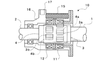
図2は、センサ部10の機構の一例を示す一部断面側面図である。この実施例に係るトルクセンサは、自動車のステアリングシャフトのトーションバーに負荷されるねじれトルクを検出する。公知のように、ステアリングシャフトにおいては入力軸(第1の回転軸)1と出力軸(第2の回転軸)2とがトーションバー(図示せず)を介して連結されている。入力軸1及び出力軸2はトーションバーによるねじれ変形の許す限りの限られた角度範囲(例えば最大でも+6度〜−6度程度の範囲)で相対的に回転しうる。センサ部10は、トーションバーの周囲に設置される。センサ部10は、第1のコイル11、第2のコイル12、入力軸(第1の回転軸)1に連結された第1の磁気応答部材3、出力軸(第2の回転軸)2に連結された第2の磁気応答部材4を含む。第1及び第2の磁気応答部材3,4は、例えば、円筒形状を成した良導電性かつ非磁性(反磁性)の材質(例えば、アルミニウムあるいは銅など)からなり、それぞれ、円周方向に沿って所定ピッチ(角度)で複数の開口窓3a,3b,4a,4bを2列備えている。
FIG. 2 is a partial cross-sectional side view showing an example of the mechanism of the
図示のよう組み立てられた状態において、第1の磁気応答部材3の円筒と第2の磁気応答部材4の円筒とが重なり合い、該円筒の重なり合いの内側にトーションバー(図示せず)が位置する。第1の磁気応答部材3の開口窓3aの列と第2の磁気応答部材4の開口窓4aの列とが重複し、その周りに第1のコイル11が配置される。また、第1の磁気応答部材3の開口窓3bの列と第2の磁気応答部材4の開口窓4bの列とが重複し、その周りに第2のコイル12が配置される。第1の磁気応答部材3の円筒と第2の磁気応答部材4の円筒との相対的回転位置つまりトーションバーのねじれ角に応じて、各列における開口窓3a,4a,3b,4bの重なり具合が変化する。開口窓3aと4a(又は3bと4b)が全く重なっていない状態では、コイル11(又は12)の内周はすべて磁気応答部材3(又は4)の円筒材質で覆われ、渦電流損失が最大となり、該コイル11(又は12)のインダクタンス(インピーダンス)は最小となる。逆に、開口窓3aと4a(又は3bと4b)が完全に重なっている状態では、コイル11(又は12)の内周を覆う磁気応答部材3(又は4)の円筒材質の面積は最小となるので渦電流損失が最小となり、かつ、該重なった開口の空間を介して内側のトーションバー(磁性体)に対する磁気結合が最大となるので、該コイル11(又は12)のインダクタンス(インピーダンス)は最大となる。
In the assembled state as illustrated, the cylinder of the first
一方、各列における開口窓3a,4a,3b,4bの重なり具合の変化は互いに逆特性となるように、開口窓の配置を適切にずらして設定している。例えば、第1の磁気応答部材3においては、開口窓3aの列(第1の列)と、開口窓3bの列(第2の列)とは、開口窓の繰り返しサイクルに関して、丁度の1/2サイクルの位相ずれを持つように開口窓列を形成(配置)する。その場合、第2の磁気応答部材4においては、開口窓4aの列(第1の列)と、開口窓4bの列(第2の列)とは、開口窓の繰り返しサイクルに関して、丁度、同相となるように開口窓列を形成(配置)する。また、トーションバーのねじれ角が0の状態において、図示例のように、第1の列における開口窓3a,4aの重なり具合は丁度半分となり、第2の列における開口窓3b,4bの重なり具合も丁度半分となるように、各開口窓列を形成(配置)する。ねじれ角が0の状態から、時計方向にねじれ角が生じると、例えば、第1の列における開口窓3a,4aの重なり具合が増大してそれに対応する第1のコイル11のインダクタンス(インピーダンス)が増加するのに対して、第2の列における開口窓3b,4bの重なり具合が減少してそれに対応する第2のコイル12のインダクタンス(インピーダンス)が減少する。また、ねじれ角が0の状態から、反時計方向にねじれ角が生じると、第1の列における開口窓3a,4aの重なり具合が減少してそれに対応する第1のコイル11のインダクタンス(インピーダンス)が減少するのに対して、第2の列における開口窓3b,4bの重なり具合が増加してそれに対応する第2のコイル12のインダクタンス(インピーダンス)が増加する。
On the other hand, the arrangement of the opening windows is appropriately shifted so that changes in the overlapping state of the
このように、センサ部10においては、入出力軸(第1及び第2の回転軸)1,2の相対的回転位置に応答して互いに逆特性のインピーダンス変化を該第1及び第2のコイル11,12に生じさせるように、第1及び第2の磁気応答部材3,4を構成しかつ該第1及び第2のコイル11,12を配置している。なお、このようなセンサ部10の構成それ自体は、特開平8−114518号その他で公知である。よって、センサ部10の具体的構成は、図示の例に限らず、検出すべきトルク(ねじれ角)に対して逆特性の2つの出力を生じさせることのできる構成であれば、どのような構成であってもよい。
As described above, in the
図1に戻り、センサ部10内において、前記第1のコイル11と第2のコイル12とは直列接続されており、第1のコイル11と第2のコイル12との接続点S(中点)からコイル出力交流電圧を取り出すようになっている。また、第1のコイル11と第2のコイル12とは近接して配置されて互いが同じ温度環境におかれるため、コイル11,12それぞれで生じうる温度ドリフトによるインピーダンス変化特性は同じとなる。直列接続されたコイル11,12のインピーダンスの分圧比に応じて取り出されるコイル出力交流電圧においては、分圧比の分子と分母に温度ドリフトによるインピーダンス変化分がそれぞれ含まれるので該温度ドリフトによるインピーダンス変化分が相殺又は除去されることになる。このように、センサ部10は簡単な構成であるにも関わらず、コイル11,12の温度ドリフト特性を補償するのに都合がよいものとなっている。図2において、第1回路部20内の各回路を搭載した回路基板がセンサ部10のケーシング16内の基板収納スペース15内に収納され、合成樹脂によってモールドされている。センサ部10と検出回路部20との間を接続する電気配線を着脱するために、センサ部10のケーシング16にはコネクタ17が設けられている。
Returning to FIG. 1, the
ケーシング16の側(センサ部10及び第1回路部20の側)と第2回路部30との間を接続する伝送線(電気配線)は、コイル励磁用交流信号供給ライン18a、メイン検出出力ライン18b、サブ検出出力ライン18c、直流電源ライン18d、アースライン18eからなる。
Transmission lines (electrical wiring) connecting the
第2回路部30は、自動車のECU(電子制御装置)に相当し、ECUのプリント回路基板上に搭載されたマイクロコンピュータ31と周辺回路素子とを含んでいる。マイクロコンピュータ31は、内部クロックに基づき所定の交流周波数の信号波形Aをデジタル的に発生するように構成されている。一例として、マイクロコンピュータ31が持つクロック発生機能を使用して、センサ部10のコイル11、12を励磁するための交流信号の所望周波数に等しいクロック信号(例えばデューティ比50%)を信号波形Aとして発生し、出力ポートから出力する。クロック信号波形Aはオープンコレクタ出力回路32及びコイル励磁用交流信号供給ライン18aを介して第1回路部20内の疑似SIN波生成回路22に供給される。疑似SIN波生成回路22は、供給されたクロック信号波形Aに基づき、所定の直流電圧が加算された疑似SIN波励磁用交流信号Bを生成する。疑似SIN波生成回路22は、矩形波を疑似SIN波に変換するアナログ回路と電圧加算回路とで構成することができる。なお、励磁用交流信号を生成するための回路22としては、疑似SIN波生成回路に限らず、三角波状の交流信号を生成するもの、あるいはより精密なSIN波を生成するものなど、如何なる構成のものであってもよい。
The second circuit unit 30 corresponds to an ECU (electronic control unit) of an automobile and includes a
なお、マイクロコンピュータ31は、自動車におけるECU内に搭載されている既存のマイクロコンピュータを使用する形態に限らず、本発明に係るトルクセンサのために専用のものを用意してもよい。勿論、マイクロコンピュータ31に代えて、本発明を実施するために必要な制御・演算性能と同等の機能を達成するように構成した専用デジタル回路(クロック発生器、論理回路、計算回路、メモリ等を含むディスクリート回路若しくはICあるいはDSPなど)を用いてもよい。マイクロコンピュータ及び専用デジタル回路を総称してデジタル処理装置という。
Note that the
交流信号生成回路22で生成した励磁用交流信号Bはコイル駆動回路21に供給される。コイル駆動回路21は、直流バイアスされているコイル励磁用交流信号をコイル11、12の直列回路に印加する。基準電圧発生回路23は、第2回路部30から直流電源ライン18dを介して供給される所定の直流電圧に基づいて、第1回路部20内において所定の交流電圧を直流バイアスするための任意の電圧値の直流電圧を発生する。
The excitation AC signal B generated by the AC
第1のコイル11と第2のコイル12との接続点S(中点)から取り出されたコイル出力交流電圧は、第1の差動増幅回路26(第1の回路に相当)の「+入力」に入力される。第1の基準信号生成回路25はコイル駆動回路21から出力されたコイル励磁用交流信号を入力し、該コイル励磁用交流信号のオフセットレベル(トルク0のときの振幅レベル)を調節し、該オフセットレベル調節された基準交流電圧を出力する。第1の基準信号生成回路25から出力された基準交流電圧は、第1の差動増幅回路26の「-入力」に入力される。第1の差動増幅回路26では、コイル出力交流電圧(+入力)とコイル励磁用交流信号に基づく基準交流電圧(−入力)との差信号を求める。このように差動増幅演算を行う理由は、コイル出力交流電圧から検出トルクに起因する成分を抽出し、トルク検出のダイナミックレンジを大きくとる(感度を上げる)ことができるようにするためである。第1の差動増幅回路26から出力されるトルク検出信号(交流信号)はコンデンサC1を介して第1の増幅回路27に入力され、基準電圧発生回路23から与えられる所定の基準直流電圧Vref(オフセット電圧OF1)と加算されることで、直流バイアスされ、正電圧側にオフセットされる。すなわち、第1の差動増幅回路26から出力される差信号は、オフセット電圧OF1の加算(オフセット)によって、正電圧の領域でのみ振動するものとなる。第1の増幅回路27から出力される直流バイアスされたトルク検出信号(交流信号)は、メイントルク検出信号Cとしてメイン検出出力ライン18bを介して第2回路部30に伝送され、マイクロコンピュータ31のA/Dポート(アナログ/デジタル変換入力ポート)#1に入力される。これにより、トルク検出値のサンプリングを行う際に、正の値でのみトルク検出値のサンプリング値が得られるようにすることを可能にする。
The coil output AC voltage taken out from the connection point S (middle point) between the
また、第1のコイル11と第2のコイル12との接続点S(中点)から取り出されたコイル出力交流電圧は、第2の差動増幅回路26´の「−入力」にも入力される。第2の基準信号生成回路25´はコイル駆動回路21から出力されたコイル励磁用交流信号を入力し、該コイル励磁用交流信号のオフセットレベル(トルク0のときの振幅レベル)を調節し、該オフセットレベル調節された基準交流電圧を出力する。第2の基準信号生成回路25´から出力された基準交流電圧は、第2の差動増幅回路26´(第2の回路に相当)の「+入力」に入力される。第2の差動増幅回路26´では、コイル出力交流電圧(−入力)とコイル励磁用交流信号に基づく基準交流電圧(+入力)との差信号を求める。第2の差動増幅回路26´から出力されるトルク検出信号(交流信号)はコンデンサC2を介して第2の増幅回路27´に入力され、直流電圧(オフセット電圧OF2)と加算されることで、直流バイアスされる。
The coil output AC voltage taken out from the connection point S (middle point) between the
コイル直流抵抗検出回路28は、第1のコイル11と第2のコイル12との接続点S(中点)から取り出されたコイル出力交流電圧に含まれる直流電圧成分を抽出する。ここで抽出される直流電圧成分は、コイル11又は12に断線、半断線等の故障がなければ、コイル駆動回路21によりバイアスされた所定の直流電圧に対応するものとなり、変動が生じないが、断線、半断線等の故障が起きた場合は、それに応じて変動したレベルを持つものとなる。すなわち、コイル11又は12に関する断線、半断線等に関する故障情報を含んでいる。
The coil DC resistance detection circuit 28 extracts a DC voltage component included in the coil output AC voltage extracted from the connection point S (middle point) between the
励磁信号振幅検出&加算回路29は、コイル駆動回路21から出力されたコイル励磁用交流信号の交流成分のみを整流し、該励磁用交流信号のピーク振幅値に相当する直流電圧を抽出する。ここで抽出される直流電圧は、励磁用交流信号に異常がなければ所定レベルを維持しているが、励磁用交流信号供給ライン18aのコネクタの外れや接触不良、断線、半断線など、なんらかの異常があれば、それに応じて変動したレベルを持つものとなる。すなわち、励磁用交流信号の供給系統に関する故障情報を含んでいる。
The excitation signal amplitude detection &
そして、励磁信号振幅検出&加算回路29は、コイル直流抵抗検出回路28によって抽出したコイル出力交流電圧に含まれる直流電圧成分と、コイル励磁用交流信号の交流成分のみを整流して抽出した直流電圧とを加算した直流電圧(オフセット電圧OF2)を生成する。これにより、オフセット電圧OF2は、コイル11又は12に関する断線、半断線等に関する故障情報と励磁用交流信号の供給系統に関する故障情報の両方を含むものとなる。ただし、こうした故障が生じていない場合、オフセット電圧OF2は基準電圧発生回路23から第1の増幅回路27に対して与えられる所定の基準直流電圧Vref(オフセット電圧OF1)と同じ電圧値となるように調節される。これらのコイル直流抵抗検出回路28,励磁信号振幅検出&加算回路29は、オフセット電圧生成回路に該当する。
The excitation signal amplitude detection &
第2の増幅回路27´では、前記オフセット電圧OF2を前記差信号に加算し、該差信号をオフセット電圧OF2によって正側にオフセットする。すなわち、第2の差動増幅回路26´から出力される差信号は、オフセット電圧OF2の加算(オフセット)によって、正電圧の領域でのみ振動するものとなり、かつ、該オフセット電圧OF2が持つ上記故障情報を含むものとなる。第2の増幅回路27´から出力される直流バイアスされたトルク検出信号(交流信号)は、サブトルク検出信号としてサブ検出出力ライン18cを介して第2回路部30に伝送され、マイクロコンピュータ31のA/Dポート(アナログ/デジタル変換入力ポート)#2に入力される。これによって、1本のサブ検出出力ライン18cで伝送されるサブトルク検出信号D中に、トルク検出情報と故障情報を含ませることができる。なお、メイントルク検出信号Cを求めるための第1の差動増幅回路26と、サブトルク検出信号Dを求めるための第2の差動増幅回路26´との間では、その+入力及び−入力に入力されるコイル出力交流電圧と基準交流電圧の関係が逆(逆極性)になっているので、検出対象トルクに対するメイントルク検出信号Cとサブトルク検出信号Dの特性が互いに逆特性となるようにされている。例えば、トルクの漸次増大に伴って、メイントルク検出信号Cのトルク検出値が漸次増大するとすると、サブトルク検出信号Dのトルク検出値は漸次減少するような関係(逆特性)となるようにされている。
In the
なお、第1又は第2の基準信号生成回路25,25´及び第1又は第2の増幅回路27,27´に付属して設けられている可変抵抗器として、デジタルポテンショ(デジタル制御可能な可変抵抗器)が用いられており、デジタルポテンショ通信インターフェース24を介して、マイクロコンピュータ31からの制御に従いこれらの抵抗値が可変調整されるようになっており、これにより、第1又は第2の基準信号生成回路25,25´に対するコイル励磁用交流信号のオフセットレベル(トルク0のときの振幅レベル)調整及び第1又は第2の増幅回路27,27´に対するゲイン調節を行うことができる。
In addition, as a variable resistor provided attached to the first or second reference
図3はトルク検出処理及び故障診断処理の動作例を説明するためのタイムチャートであり、横軸が時間軸である。図3において、Aはマイクロコンピュータ31が発生する所定の交流周波数の信号波形(クロック信号)Aを示し、Bは該信号波形Aに応じて疑似SIN波生成回路22が発生する励磁用交流信号Bを示し、疑似SIN波からなり、所定の直流電圧が加算されている。
FIG. 3 is a time chart for explaining an operation example of the torque detection process and the failure diagnosis process, and the horizontal axis is the time axis. 3, A indicates a signal waveform (clock signal) A of a predetermined AC frequency generated by the
CKsは、マイクロコンピュータ31内で発生されるサンプリングクロックを示し、クロック信号Aと同一周期であって、クロック信号Aの立ち上がり時から時間Ts経過した時に発生される。図中、時間Tgは、励磁用交流信号Bの疑似SIN波における最小値から最大値までの時間を示し、通常、クロック信号Aの半周期の時間である。また、サンプリングクロックCKmは、クロック信号Aと同一周期であって、サンプリングクロックCKsの発生タイミングから時間Tg後に発生される。すなわち、サンプリングクロックCKsとCKmは、半周期の位相ずれを持つ2相クロックである。
CKs indicates a sampling clock generated in the
図3において、Cは、第1の増幅回路27からメイン検出出力ライン18bを経てマイクロコンピュータ31のA/Dポート#1に入力されるメイントルク検出信号Cの一例を示す。Dは、第2の増幅回路27´からサブ検出出力ライン18cを経てマイクロコンピュータ31のA/Dポート#2に入力されるサブトルク検出信号Dの一例を示す。なお、サンプリングクロックCKsは、クロック信号Aと同一周期に限らず、クロック信号Aの2倍周期等であってもよく、要するに整数倍の周期であればよい。
3, C indicates an example of the main torque detection signal C input from the
概して、検出したトルクに対応するコイルのインピーダンスを検出するためには、その出力交流電圧のピーク値のレベルを検出する。一方、特定の位相タイミングでサンプリングを行う場合は、必ずしも、ピーク値のタイミングでサンプリングを行わなくてもインピーダンス検出は可能であり、要は、常に同じ位相タイミングでサンプリングを行えばよい。例えば、サンプリングクロックCKsは、コイル出力交流電圧のピーク値の近傍に対応して前記差信号をサンプリングするように、サンプリングタイミングを設定している。 Generally, in order to detect the impedance of the coil corresponding to the detected torque, the level of the peak value of the output AC voltage is detected. On the other hand, when sampling is performed at a specific phase timing, the impedance can be detected without necessarily performing sampling at the peak value timing. In short, the sampling may always be performed at the same phase timing. For example, the sampling clock CKs sets the sampling timing so as to sample the difference signal corresponding to the vicinity of the peak value of the coil output AC voltage.
サンプリングクロックCKsは、検出出力交流電圧C,Dの正のピークの近傍で発生し、該検出出力交流電圧C,Dの正(上)のピークの近傍の値をサンプリングするために使用される。サンプリングクロックCKmは、前記検出出力交流電圧C,Dの負のピークの近傍で発生し、該検出出力交流電圧C,Dの負(下)のピークの近傍の値をサンプリングするために使用される。 The sampling clock CKs is generated in the vicinity of the positive peak of the detection output AC voltages C and D, and is used to sample a value in the vicinity of the positive (upper) peak of the detection output AC voltages C and D. The sampling clock CKm is generated in the vicinity of the negative peak of the detection output AC voltages C and D, and is used to sample a value in the vicinity of the negative (lower) peak of the detection output AC voltages C and D. .
図4は、マイクロコンピュータ31が実行するトルク検出処理の一例を示す。ステップS1では、上サンプリングクロックCKsの発生タイミングかを判定する。上サンプリングクロックCKsのタイミングであれば、ステップS2では、A/Dポート#1,#2からの前記各トルク検出信号C,Dのデジタルデータをサンプリングし、サンプリングした各データを上ピークのホールド値U1,U2として所定のレジスタ内にホールドする。次に、ステップS3では、下サンプリングクロックCKmの発生タイミングかを判定する。下サンプリングクロックCKmのタイミングであれば、ステップS4では、A/Dポート#1,#2からの前記各トルク検出信号C,Dのデジタルデータをサンプリングし、サンプリングした各データを下ピークのホールド値D1,D2として所定のレジスタ内にホールドする。ステップS5では、それぞれ、第1のコイル11に関する上ピークのホールド値U1と下ピークのホールド値D1の差U1−D1と、第2のコイル12に関する上ピークのホールド値U2と下ピークのホールド値D2の差U2−D2を演算し、メイントルク検出信号Cに関する第1(メイン)のトルク検出データTDD1とサブトルク検出信号Dに関する第2(サブ)のトルク検出データTDD2を得る。次のステップS6では、第1(メイン)のトルク検出データTDD1をトルク検出データとして出力する。第2(サブ)のトルク検出データTDD2は、後述の故障診断に際して利用される。なお、各トルク検出信号C又はDにはオフセット電圧OF1又はOF2が含まれているが、上述のように、上ピークと下ピークの差を演算することによりトルク検出データTDD1又はTDD2を得ているので、オフセット電圧OF1又はOF2が自動的に相殺される。なお、ステップS6において、第2(サブ)のトルク検出データTDD2をトルク検出データとして出力するようにしてもよい。
FIG. 4 shows an example of torque detection processing executed by the
例えば、図3に示されたCの例では、サンプリングクロックCKsの発生タイミングにおけるメイントルク検出信号Cのデジタル値がL1であり、この値L1が上ピークのホールド値U1としてレジスタ内にホールドされる。また、サンプリングクロックCKmの発生タイミングにおけるメイントルク検出信号Cのデジタル値がL2であり、この値L2が下ピークのホールド値D1としてレジスタ内にホールドされる。そして、上ピークのホールド値U1と下ピークのホールド値D1の差U1−D1は、「L1−L2」であり、これが第1のトルク検出データTDD1としてホールドされ、出力される。 For example, in the example of C shown in FIG. 3, the digital value of the main torque detection signal C at the generation timing of the sampling clock CKs is L1, and this value L1 is held in the register as the upper peak hold value U1. . Further, the digital value of the main torque detection signal C at the generation timing of the sampling clock CKm is L2, and this value L2 is held in the register as the lower peak hold value D1. The difference U1-D1 between the upper peak hold value U1 and the lower peak hold value D1 is “L1−L2”, which is held and output as the first torque detection data TDD1.
例えば、第1のトルク検出データTDD1のとりうる最小値は、上ピークのホールド値U1のとりうる最小値(例えば略OF1)と下ピークのホールド値D1のとりうる最大値(例えば略OF1)との差であるから略0であり(例えばU1−D1=略OF1−略OF1=0)、一方、トルク検出データTDD1のとりうる最大値は、U1のとりうる最大値とD1のとりうる最小値との差であるから、差Dのとりうる所定の最大値に近いものとなる。従って、ダイナミックレンジが拡大されていることが理解できる。従って、高感度でトルク検出を行うことができる。 For example, the minimum value that the first torque detection data TDD1 can take is the minimum value that the upper peak hold value U1 can take (for example, approximately OF1) and the maximum value that the lower peak hold value D1 can take (for example, approximately OF1). Therefore, the maximum value that can be taken by the torque detection data TDD1 is the maximum value that can be taken by U1 and the minimum value that can be taken by D1. Therefore, it is close to a predetermined maximum value that can be taken by the difference D. Therefore, it can be understood that the dynamic range is expanded. Therefore, torque detection can be performed with high sensitivity.
なお、図3に示されたDの例では、サンプリングクロックCKsの発生タイミングにおけるサブトルク検出信号Dのデジタル値がL2であり、この値L2が上ピークのホールド値U2としてレジスタ内にホールドされる。また、サンプリングクロックCKmの発生タイミングにおけるサブトルク検出信号Dのデジタル値がL1であり、この値L1が下ピークのホールド値D2としてレジスタ内にホールドされる。そして、上ピークのホールド値U2と下ピークのホールド値D2の差U2−D2は、「L2−L1」であり、これが第2のトルク検出データTDD2としてホールドされ、出力される。 In the example of D shown in FIG. 3, the digital value of the sub-torque detection signal D at the generation timing of the sampling clock CKs is L2, and this value L2 is held in the register as the upper peak hold value U2. Further, the digital value of the sub-torque detection signal D at the generation timing of the sampling clock CKm is L1, and this value L1 is held in the register as the lower peak hold value D2. The difference U2-D2 between the upper peak hold value U2 and the lower peak hold value D2 is "L2-L1", which is held and output as the second torque detection data TDD2.
図5は、第1(メイン)及び第2(サブ)のトルク検出データTDD1,TDD2の値と検出トルク(相対回転位置)との間の相関関係の一例を示すグラフである。このように、第1(メイン)のトルク検出データTDD1の関数と第2(サブ)のトルク検出データTDD2の関数とは、検出トルク(相対回転位置)に関して逆特性を示し、正常であれば、両者を加算した値TCは常に略一定値となる。なお、横軸において、「0」の位置はトルク0の位置を示し、その右側の「+」で記した領域は例えば時計方向のねじれに応じた領域を示し、左側の「−」で記した領域は例えば反時計方向のねじれに応じた領域を示す。図5では、トルク検出データTDD1,TDD2の値と検出トルク(相対回転位置)との間の相関関係は、リニア特性を示しているが、これに限らず、非リニア特性であってもよい。 FIG. 5 is a graph showing an example of the correlation between the values of the first (main) and second (sub) torque detection data TDD1, TDD2 and the detected torque (relative rotational position). As described above, the function of the first (main) torque detection data TDD1 and the function of the second (sub) torque detection data TDD2 exhibit reverse characteristics with respect to the detected torque (relative rotational position). The value TC obtained by adding both is always a substantially constant value. On the horizontal axis, the position of “0” indicates the position of torque 0, the area indicated by “+” on the right side thereof indicates, for example, the area corresponding to the clockwise twist, and indicated by “−” on the left side. An area | region shows the area | region according to the twist of a counterclockwise direction, for example. In FIG. 5, the correlation between the values of the torque detection data TDD1 and TDD2 and the detected torque (relative rotational position) shows linear characteristics, but is not limited to this, and may be non-linear characteristics.
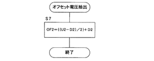
図6は、マイクロコンピュータ31が実行するオフセット電圧抽出処理の一例を示す。ステップS7では、前記ステップS2及びS4でホールドしたデータを用い、交流成分の振れの中心に相当する電圧を抽出するための、
OF2={(U2−D2)/2}+D2
なる式に従い、第2(サブ)のオフセット電圧OF2を抽出する。つまり、第2(サブ)の検出データ(サブトルク検出信号D)の上ピークホールド値U2から下ピークのホールド値D2を引き、それを2で割り、D2を加算することにより、オフセット電圧OF2を抽出する。なお、本実施例においては故障判定処理に当たってオフセット電圧OF2のみを用いているので図6の電圧抽出処理においてはオフセット電圧OF2のみを抽出するようにしているが、オフセット電圧OF1も使用する実施形態を採用する場合は、
OF1={(U1−D1)/2}+D1
なる式に従い、第1(メイン)のオフセット電圧OF1を抽出する処理ステップを追加するようにすればよい。
FIG. 6 shows an example of an offset voltage extraction process executed by the
OF2 = {(U2-D2) / 2} + D2
The second (sub) offset voltage OF2 is extracted according to the following equation. That is, the offset voltage OF2 is extracted by subtracting the lower peak hold value D2 from the upper peak hold value U2 of the second (sub) detection data (sub torque detection signal D), dividing it by 2, and adding D2. To do. In the present embodiment, since only the offset voltage OF2 is used in the failure determination process, only the offset voltage OF2 is extracted in the voltage extraction process of FIG. 6, but an embodiment using the offset voltage OF1 is also used. When adopting,
OF1 = {(U1-D1) / 2} + D1
A processing step for extracting the first (main) offset voltage OF1 may be added according to the following equation.
図7は、マイクロコンピュータ31が実行する故障診断処理の一例を示すものである。ステップS10は、第1(メイン)のトルク検出データTDD1と第2(サブ)のトルク検出データTDD2との加算値TC(=TDD1+TDD2)が所定の正常値の範囲内であるか否かを判定する。前述の通り、正常であれば該加算値TCは常に略一定の正常値を示すので、該ステップS10がNOの場合は、コイルが異常である旨の警報信号を出力する(ステップS15)。
FIG. 7 shows an example of a failure diagnosis process executed by the
ステップS11〜S14では、上記抽出したオフセット電圧OF2に基づき故障診断を行う。前述の通り、コイル内の断線、半断線(切れかかり)、あるいはショートなどが生じている場合、あるいはコイル接続端子部分での接触不良、接続外れ、接続コネクタの異常、接続ケーブルの異常などが生じている場合などには、サブトルク検出信号D中の直流成分に異常が生じる。このようなサブトルク検出信号D中の直流成分の異常を検出するために、オフセット電圧OF2がトルク検出信号D中に含まれるようになっており、これは図6のルーチンで抽出される。従って、ステップS11〜S14において、抽出したオフセット電圧OF2に基づきこれらの異常検出を容易に行うことができる。 In steps S11 to S14, failure diagnosis is performed based on the extracted offset voltage OF2. As described above, when a broken wire, half-broken wire (short cut), short circuit, etc. occur in the coil, contact failure at the coil connection terminal, disconnection, connection connector failure, connection cable failure, etc. In such a case, an abnormality occurs in the DC component in the sub-torque detection signal D. In order to detect the abnormality of the DC component in the sub torque detection signal D, the offset voltage OF2 is included in the torque detection signal D, and this is extracted by the routine of FIG. Therefore, in steps S11 to S14, it is possible to easily detect these abnormalities based on the extracted offset voltage OF2.
ステップS11では、サブトルク検出信号Dから抽出したオフセット電圧OF2が所定の上限値OFmaxより大きいかを判定する。ステップS12では、オフセット電圧OF2が所定の下限値OFminより小さいかを判定する。オフセット電圧OF2が所定の上限値OFmaxと下限値OFminの範囲内に収まっていれば、サブトルク検出信号Dに含まれる直流成分が異常ではないことを意味する。ステップS11とS12が共にNOであれば、検出用コイル11,12の直流成分に異常がないことを意味する。その場合は、ステップS13でコイル11,12が正常である旨の判定を行う。一方、ステップS11又はS12がYESであれば、検出用コイル11,12の直流成分に異常があることを意味する。その場合は、ステップS14でコイルの直流成分が異常である旨の判定を下し、その旨の警報信号を出力する。
In step S11, it is determined whether or not the offset voltage OF2 extracted from the sub torque detection signal D is larger than a predetermined upper limit value OFmax. In step S12, it is determined whether the offset voltage OF2 is smaller than a predetermined lower limit value OFmin. If the offset voltage OF2 is within the range between the predetermined upper limit value OFmax and the lower limit value OFmin, it means that the DC component included in the sub torque detection signal D is not abnormal. If both steps S11 and S12 are NO, it means that there is no abnormality in the DC components of the detection coils 11 and 12. In that case, it is determined in step S13 that the
なお、オフセット電圧OF1及びOF2の両方を用いてコイル直流成分に関連する故障判定を行うことも可能である。その場合は、ステップS11〜S14に代えて、例えばOF1=OF2が成立するか否かの判定を行い、YESである場合には正常と判定し、NOである場合には異常であると判定する。すなわち、正常であればOF2がOF1(所定の基準直流電圧Vref)と同じであるはずであるからである。なお、その場合、OF1=OF2が成立するとは、両者の値が完全に一致していることのみを意味するのではなく、所定の許容範囲内で両者の値が略一致している場合をも含む。すなわち、|OF1−OF2|(OF1とOF2の差の絶対値)が所定範囲(許容範囲)内であるときを正常と判定し、所定範囲外であるときを異常と判定するようにしてもよい。 It is also possible to make a failure determination related to the DC component of the coil using both offset voltages OF1 and OF2. In that case, instead of steps S11 to S14, for example, whether or not OF1 = OF2 is determined is determined. If YES, it is determined to be normal, and if NO, it is determined to be abnormal. . That is, if normal, OF2 should be the same as OF1 (predetermined reference DC voltage Vref). In this case, the fact that OF1 = OF2 does not only mean that both values are completely coincident with each other, but there is a case where both values are substantially coincident within a predetermined allowable range. Including. That is, when | OF1−OF2 | (the absolute value of the difference between OF1 and OF2) is within a predetermined range (allowable range), it may be determined as normal, and when it is out of the predetermined range, it may be determined as abnormal. .
なお、励磁信号振幅検出&加算回路29から出力される、コイル11又は12に関する断線、半断線等に関する故障情報と励磁用交流信号の供給系統に関する故障情報の両方を含むオフセット電圧OF2を第1の増幅回路27に入力するようにしてもよく、その場合は、該第1の増幅回路27では該オフセット電圧OF2を前記第1の差動増幅回路26からの差信号に加算し、該第1の増幅回路27から出力されるメイントルク検出信号Cにトルク検出情報と故障情報とが含まれることになる。なお、その場合、第2の増幅回路27´に入力するオフセット電圧としてはOF2に代えてOF1を用いるようにしてよい。あるいは、前記オフセット電圧OF2を第1の増幅回路27と第2の増幅回路27´の両方に入力するようにしてもよく、その場合はメイントルク検出信号C及びサブトルク検出信号Dの両方にトルク検出情報と故障情報とが含まれることになる。すなわち、メイントルク検出信号C又はサブトルク検出信号Dの少なくとも一方にトルク検出情報と故障情報とが含まれていればよい。その場合、トルク検出情報と故障情報との双方を含むトルク検出信号(メイントルク検出信号C又はサブトルク検出信号D)から抽出したオフセット電圧(OF2)に基づいて故障判定を行えばよい。
The offset voltage OF2 including both failure information relating to the disconnection, half-breakage, etc. relating to the
1…入力軸
2…出力軸
3,4…磁気応答部材
3a,3b,4a,4b…開口窓
10…センサ部
11,12…コイル
15…基板収納スペース
16…ケーシング
17…コネクタ
18a…コイル励磁用交流信号供給ライン
18b…メイン検出出力ライン
18c…サブ検出出力ライン
18d…直流電源ライン
18e…アースライン
20…第1回路部
21…コイル駆動回路
22…疑似SIN波生成回路
23…基準電圧発生回路
24…デジタルポテンショ通信インターフェース
25…第1の基準信号生成回路
25´…第2の基準信号生成回路
26…第1の差動増幅回路
26´…第2の差動増幅回路
27…第1の増幅回路
27´…第2の増幅回路
28…コイル直流抵抗検出回路
29…励磁信号振幅検出&加算回路
30…第2回路部
31…マイクロコンピュータ
32…オープンコレクタ回路
DESCRIPTION OF SYMBOLS 1 ...
Claims (8)
直列接続された2つのコイル、前記第1の回転軸に連結された第1の磁気応答部材、前記第2の回転軸に連結された第2の磁気応答部材を含み、前記第1及び第2の回転軸の相対的回転位置に応答してインピーダンス変化を該コイルに生じさせるように前記第1及び第2の磁気応答部材を構成したセンサ部と、ここで、該センサ部は前記直列接続された2つのコイルから1つのコイル出力交流信号を生じるものであり、
所定の励磁用交流信号を前記コイルに印加するコイル駆動回路と、
前記コイル出力交流信号に含まれる検出出力交流電圧成分と前記励磁用交流信号に基づく基準交流電圧成分との差を求める第1回路と、
前記コイル出力交流信号に含まれる検出出力交流電圧成分と前記励磁用交流信号に基づく基準交流電圧成分との差を、前記第1回路における差演算とは逆極性で、求める第2回路と、
前記コイル出力交流信号に含まれる直流電圧成分及び前記励磁用交流信号のピーク振幅値に相当する直流電圧の少なくとも一方に対応する電圧を、故障診断用のオフセット電圧として生成するオフセット電圧生成回路と、
前記第1回路の出力を第1の直流電圧でオフセットしてメイントルク検出信号を出力し、前記第2回路の出力を第2の直流電圧でオフセットしてサブトルク検出信号を出力する第1及び第2の増幅回路と、ここで、前記第1の直流電圧及び第2の直流電圧の少なくとも一方が前記オフセット電圧生成回路から生成された前記オフセット電圧であり、
前記メイントルク検出信号又はサブトルク検出信号に含まれる交流成分の振れ幅を検出することにより、前記コイルの前記インピーダンス変化に応答する検出データをトルク検出データとして取得するトルク検出部と、
前記オフセット電圧でオフセットされた前記メイントルク検出信号又はサブトルク検出信号に関して、該信号中の交流成分の振れの中心に相当する電圧を前記オフセット電圧として抽出するオフセット電圧抽出部と、
前記抽出したオフセット電圧に基づいて、前記コイル出力交流信号に含まれる直流電圧成分及び前記励磁用交流信号のピーク振幅値に相当する直流電圧の少なくとも一方に関する故障の有無を判定する故障診断部と
を具備することを特徴とするトルクセンサ。 A torque sensor for detecting torque generated in the first and second rotating shafts connected via a torsion bar;
Including two coils connected in series, a first magnetic response member connected to the first rotation shaft, and a second magnetic response member connected to the second rotation shaft, the first and second A sensor unit configured with the first and second magnetic response members to cause an impedance change in the coil in response to a relative rotational position of the rotation axis of the rotation axis, wherein the sensor unit is connected in series. One coil output AC signal from two other coils,
A coil drive circuit for applying a predetermined excitation AC signal to the coil;
A first circuit for obtaining a difference between a detection output AC voltage component included in the coil output AC signal and a reference AC voltage component based on the excitation AC signal;
A second circuit for obtaining a difference between a detection output AC voltage component included in the coil output AC signal and a reference AC voltage component based on the excitation AC signal with a polarity opposite to that of the difference calculation in the first circuit;
An offset voltage generation circuit that generates a voltage corresponding to at least one of a DC voltage component included in the coil output AC signal and a DC voltage corresponding to a peak amplitude value of the excitation AC signal as an offset voltage for fault diagnosis;
The first and second outputs output the main torque detection signal by offsetting the output of the first circuit with a first DC voltage, and output the sub torque detection signal by offsetting the output of the second circuit with a second DC voltage. 2, wherein at least one of the first DC voltage and the second DC voltage is the offset voltage generated from the offset voltage generation circuit,
A torque detection unit that acquires detection data in response to the impedance change of the coil as torque detection data by detecting a swing width of an AC component included in the main torque detection signal or the sub-torque detection signal;
With respect to the main torque detection signal or sub torque detection signal offset by the offset voltage, an offset voltage extraction unit that extracts a voltage corresponding to the center of fluctuation of an AC component in the signal as the offset voltage;
A failure diagnosing unit that determines whether or not there is a failure with respect to at least one of a DC voltage component included in the coil output AC signal and a DC voltage corresponding to a peak amplitude value of the excitation AC signal based on the extracted offset voltage; A torque sensor comprising:
前記オフセット電圧生成回路は、正常時の前記オフセット電圧として前記所定の基準直流電圧に対応する電圧を生成し、
前記オフセット電圧抽出部は、前記メイントルク検出信号から前記第1の直流電圧に対応する電圧を抽出し、前記サブトルク検出信号から前記第2の直流電圧に対応する電圧を抽出し、該抽出した電圧の一方が前記オフセット電圧に対応しており、
前記故障診断部は、前記抽出した第1及び第2の直流電圧に対応する電圧の差が所定範囲内であるとき正常と判定し、所定範囲外のとき異常と判定することを特徴とする請求項1乃至4のいずれかに記載のトルクセンサ。 One of the first DC voltage and the second DC voltage is a predetermined reference DC voltage, and the other is the offset voltage generated from the offset voltage generation circuit,
The offset voltage generation circuit generates a voltage corresponding to the predetermined reference DC voltage as the offset voltage at normal time,
The offset voltage extraction unit extracts a voltage corresponding to the first DC voltage from the main torque detection signal, extracts a voltage corresponding to the second DC voltage from the sub-torque detection signal, and extracts the extracted voltage Corresponds to the offset voltage,
The failure diagnosis unit determines normal when a difference between the extracted voltages corresponding to the first and second DC voltages is within a predetermined range, and determines an abnormality when the difference is outside the predetermined range. Item 5. The torque sensor according to any one of Items 1 to 4.
前記故障診断部は、さらに、前記第1及び第2のトルク検出データの加算値に基づき異常の有無を判定することを特徴とする請求項1乃至6のいずれかに記載のトルクセンサ。 The torque detection unit acquires first torque detection data by detecting an amplitude of an AC component included in the main torque detection signal, and detects an amplitude of an AC component included in the sub-torque detection signal. To obtain second torque detection data having a characteristic opposite to that of the first torque detection data,
The torque sensor according to any one of claims 1 to 6, wherein the failure diagnosis unit further determines whether or not there is an abnormality based on an added value of the first and second torque detection data.
所定のクロック信号の整数倍周期で正振幅領域に対応する第1のサンプリングタイミング信号と負振幅領域に対応する第2のサンプリングタイミング信号とを生成し、
前記差動増幅回路が出力する差信号の振幅値を前記第1及び第2のサンプリングタイミング信号でそれぞれサンプリングし、サンプリングした振幅値の差を求めることで前記トルク検出データを取得する、ことを特徴とする請求項1乃至7のいずれかに記載のトルクセンサ。 The torque detector
Generating a first sampling timing signal corresponding to a positive amplitude region and a second sampling timing signal corresponding to a negative amplitude region at an integer multiple of a predetermined clock signal;
Sampling the amplitude value of the difference signal output from the differential amplifier circuit with the first and second sampling timing signals, respectively, and obtaining the torque detection data by obtaining a difference between the sampled amplitude values. The torque sensor according to any one of claims 1 to 7.
Priority Applications (1)
| Application Number | Priority Date | Filing Date | Title |
|---|---|---|---|
| JP2010247387A JP5563956B2 (en) | 2010-10-15 | 2010-11-04 | Torque sensor |
Applications Claiming Priority (3)
| Application Number | Priority Date | Filing Date | Title |
|---|---|---|---|
| JP2010233056 | 2010-10-15 | ||
| JP2010233056 | 2010-10-15 | ||
| JP2010247387A JP5563956B2 (en) | 2010-10-15 | 2010-11-04 | Torque sensor |
Publications (2)
| Publication Number | Publication Date |
|---|---|
| JP2012103003A true JP2012103003A (en) | 2012-05-31 |
| JP5563956B2 JP5563956B2 (en) | 2014-07-30 |
Family
ID=46393598
Family Applications (3)
| Application Number | Title | Priority Date | Filing Date |
|---|---|---|---|
| JP2010247387A Active JP5563956B2 (en) | 2010-10-15 | 2010-11-04 | Torque sensor |
| JP2011227489A Pending JP2012103243A (en) | 2010-10-15 | 2011-10-14 | Torque sensor |
| JP2011226694A Pending JP2012103242A (en) | 2010-10-15 | 2011-10-14 | Torque sensor |
Family Applications After (2)
| Application Number | Title | Priority Date | Filing Date |
|---|---|---|---|
| JP2011227489A Pending JP2012103243A (en) | 2010-10-15 | 2011-10-14 | Torque sensor |
| JP2011226694A Pending JP2012103242A (en) | 2010-10-15 | 2011-10-14 | Torque sensor |
Country Status (1)
| Country | Link |
|---|---|
| JP (3) | JP5563956B2 (en) |
Cited By (1)
| Publication number | Priority date | Publication date | Assignee | Title |
|---|---|---|---|---|
| CN117091754A (en) * | 2023-10-20 | 2023-11-21 | 山东远盾网络技术股份有限公司 | Large-scale equipment fault detection method and system based on data analysis |
Families Citing this family (3)
| Publication number | Priority date | Publication date | Assignee | Title |
|---|---|---|---|---|
| JP6048060B2 (en) * | 2012-10-18 | 2016-12-21 | 日本精工株式会社 | Torque detection device and electric power steering device |
| JP2014224740A (en) * | 2013-05-16 | 2014-12-04 | 株式会社小野測器 | Torque sensor |
| JP7166552B2 (en) * | 2019-07-24 | 2022-11-08 | 多摩川精機株式会社 | Fastening structure between metal case for torque sensor and resin holder |
Citations (4)
| Publication number | Priority date | Publication date | Assignee | Title |
|---|---|---|---|---|
| JP2001281081A (en) * | 2000-03-31 | 2001-10-10 | Toyoda Mach Works Ltd | Torque sensor |
| JP2001336995A (en) * | 2000-05-30 | 2001-12-07 | Mitsubishi Electric Corp | Torque detector |
| JP2002107110A (en) * | 2000-09-28 | 2002-04-10 | Tadatoshi Goto | Relative rotational position detector |
| JP2004264316A (en) * | 2004-06-25 | 2004-09-24 | Koyo Seiko Co Ltd | Torque sensor |
Family Cites Families (5)
| Publication number | Priority date | Publication date | Assignee | Title |
|---|---|---|---|---|
| JPH08240492A (en) * | 1995-03-06 | 1996-09-17 | Nippon Seiko Kk | Torque sensor |
| JP3824957B2 (en) * | 2001-03-28 | 2006-09-20 | 古河電気工業株式会社 | Rotation sensor and rotor |
| JP5016165B2 (en) * | 2001-04-11 | 2012-09-05 | 株式会社アミテック | Relative rotational position detector |
| JP3936225B2 (en) * | 2001-04-12 | 2007-06-27 | 古河電気工業株式会社 | Rotation sensor |
| JP4484491B2 (en) * | 2003-10-29 | 2010-06-16 | 日立オートモティブシステムズ株式会社 | Torque sensor |
-
2010
- 2010-11-04 JP JP2010247387A patent/JP5563956B2/en active Active
-
2011
- 2011-10-14 JP JP2011227489A patent/JP2012103243A/en active Pending
- 2011-10-14 JP JP2011226694A patent/JP2012103242A/en active Pending
Patent Citations (4)
| Publication number | Priority date | Publication date | Assignee | Title |
|---|---|---|---|---|
| JP2001281081A (en) * | 2000-03-31 | 2001-10-10 | Toyoda Mach Works Ltd | Torque sensor |
| JP2001336995A (en) * | 2000-05-30 | 2001-12-07 | Mitsubishi Electric Corp | Torque detector |
| JP2002107110A (en) * | 2000-09-28 | 2002-04-10 | Tadatoshi Goto | Relative rotational position detector |
| JP2004264316A (en) * | 2004-06-25 | 2004-09-24 | Koyo Seiko Co Ltd | Torque sensor |
Cited By (2)
| Publication number | Priority date | Publication date | Assignee | Title |
|---|---|---|---|---|
| CN117091754A (en) * | 2023-10-20 | 2023-11-21 | 山东远盾网络技术股份有限公司 | Large-scale equipment fault detection method and system based on data analysis |
| CN117091754B (en) * | 2023-10-20 | 2023-12-19 | 山东远盾网络技术股份有限公司 | Large equipment fault detection method and system based on data analysis |
Also Published As
| Publication number | Publication date |
|---|---|
| JP2012103243A (en) | 2012-05-31 |
| JP2012103242A (en) | 2012-05-31 |
| JP5563956B2 (en) | 2014-07-30 |
Similar Documents
| Publication | Publication Date | Title |
|---|---|---|
| JP5398713B2 (en) | Torque sensor | |
| CN101506620B (en) | Steering angle sensor | |
| JP6550793B2 (en) | Temperature detection device and rotation angle detection device | |
| KR101637756B1 (en) | Fault diagnosis method for resolver | |
| JP5563956B2 (en) | Torque sensor | |
| US8466646B2 (en) | Apparatus and method for determining angular position | |
| JP5832751B2 (en) | Electronic circuit and magnetic field detection device capable of self-diagnosis | |
| US20130187664A1 (en) | Apparatus and method for diagnostics of a capacitive sensor | |
| US9507006B2 (en) | Method for calibrating a current transducer of the rogowski type | |
| JP5423762B2 (en) | Insulation failure diagnostic device for signal detector | |
| CN109412485B (en) | Apparatus and method for compensating position error of resolver | |
| JP4107134B2 (en) | Torque sensor | |
| JP2007315856A (en) | Compensation method and angle detection apparatus using the same in resolver angle detection | |
| JP3836046B2 (en) | Measured value detection device and torque detection device | |
| EP4105608B1 (en) | Magnetic sensor devices, systems and methods with error detection | |
| JP5473769B2 (en) | Torque sensor | |
| JP2002131084A (en) | Position detection device | |
| JP4828090B2 (en) | Relative rotational position detector | |
| JP4429986B2 (en) | Rotation sensor | |
| JP2002340612A (en) | Failure detecting method of differential transformer and device therefor | |
| CN119469499A (en) | An eddy current phase difference type shaft torque measurement device and torque measurement method thereof | |
| JP2003207365A (en) | Rotation angle sensor | |
| JP2007024556A (en) | Rotation sensor | |
| JP2007271457A (en) | Displacement sensor and rotation sensor | |
| JP2007187588A (en) | Rotation sensor |
Legal Events
| Date | Code | Title | Description |
|---|---|---|---|
| A621 | Written request for application examination |
Free format text: JAPANESE INTERMEDIATE CODE: A621 Effective date: 20130909 |
|
| A977 | Report on retrieval |
Free format text: JAPANESE INTERMEDIATE CODE: A971007 Effective date: 20140129 |
|
| A131 | Notification of reasons for refusal |
Free format text: JAPANESE INTERMEDIATE CODE: A131 Effective date: 20140204 |
|
| A521 | Request for written amendment filed |
Free format text: JAPANESE INTERMEDIATE CODE: A523 Effective date: 20140404 |
|
| TRDD | Decision of grant or rejection written | ||
| A01 | Written decision to grant a patent or to grant a registration (utility model) |
Free format text: JAPANESE INTERMEDIATE CODE: A01 Effective date: 20140513 |
|
| A61 | First payment of annual fees (during grant procedure) |
Free format text: JAPANESE INTERMEDIATE CODE: A61 Effective date: 20140613 |
|
| R150 | Certificate of patent or registration of utility model |
Ref document number: 5563956 Country of ref document: JP Free format text: JAPANESE INTERMEDIATE CODE: R150 |
|
| R250 | Receipt of annual fees |
Free format text: JAPANESE INTERMEDIATE CODE: R250 |
|
| R250 | Receipt of annual fees |
Free format text: JAPANESE INTERMEDIATE CODE: R250 |
|
| R250 | Receipt of annual fees |
Free format text: JAPANESE INTERMEDIATE CODE: R250 |
|
| R250 | Receipt of annual fees |
Free format text: JAPANESE INTERMEDIATE CODE: R250 |
|
| R250 | Receipt of annual fees |
Free format text: JAPANESE INTERMEDIATE CODE: R250 |
|
| R250 | Receipt of annual fees |
Free format text: JAPANESE INTERMEDIATE CODE: R250 |
|
| R250 | Receipt of annual fees |
Free format text: JAPANESE INTERMEDIATE CODE: R250 |
|
| R250 | Receipt of annual fees |
Free format text: JAPANESE INTERMEDIATE CODE: R250 |
|
| R250 | Receipt of annual fees |
Free format text: JAPANESE INTERMEDIATE CODE: R250 |