JP2012102601A - Height-adjustable bearing device for structure and height adjustment method of bearing device for structure - Google Patents
Height-adjustable bearing device for structure and height adjustment method of bearing device for structure Download PDFInfo
- Publication number
- JP2012102601A JP2012102601A JP2010254399A JP2010254399A JP2012102601A JP 2012102601 A JP2012102601 A JP 2012102601A JP 2010254399 A JP2010254399 A JP 2010254399A JP 2010254399 A JP2010254399 A JP 2010254399A JP 2012102601 A JP2012102601 A JP 2012102601A
- Authority
- JP
- Japan
- Prior art keywords
- base plate
- female screw
- height
- height adjustment
- screw member
- Prior art date
- Legal status (The legal status is an assumption and is not a legal conclusion. Google has not performed a legal analysis and makes no representation as to the accuracy of the status listed.)
- Granted
Links
Images


Landscapes
- Bridges Or Land Bridges (AREA)
Abstract
Description
本発明は、建築構造物や土木構造物の高さ調整支承装置と構造物支承装置の高さ調整工法に関する。 The present invention relates to a height adjustment support device for a building structure or a civil engineering structure and a height adjustment method for the structure support device.
橋梁や建築等の構造物には、橋脚等の下部構造で橋桁等の上部構造を支持する構成を採るものがあり、かかる構造物においては、下部構造と上部構造との間の支承装置が設置される。このような支承装置を用いる構造物の一例として、下部構造の上面ベースプレートを設置し、その上に支承を載せ、該支承の上に直接または支持プレートを介して上部構造を載せる構造のものがある。このような構造物においては、支承のレベル(高さおよび水平度)を正確に規制するために、ベースプレートの上面のレベルを高い精度で調整(以下、「高さ調整」という。)することが要請される。 Some structures such as bridges and buildings have a structure that supports the upper structure such as bridge girder in the lower structure such as bridge piers. In such structure, a support device between the lower structure and the upper structure is installed. Is done. As an example of a structure using such a support device, there is a structure in which an upper base plate of a lower structure is installed, a support is mounted thereon, and an upper structure is mounted directly on the support or via a support plate. . In such a structure, in order to accurately regulate the level of support (height and level), the level of the upper surface of the base plate is adjusted with high accuracy (hereinafter referred to as “height adjustment”). Requested.
従来の支承の高さ調整方法として、特開平6−2313号公報には、支承を載せるベースプレートの複数位置に雌ねじを有する貫通孔を形成し、各貫通孔に高さ調整ボルトを螺合させた状態でベースプレートを下部構造の据付け面に載せ、各高さ調整ボルトをベースプレート上面より突出しない範囲で高さ調整することによりベースプレートの高さを調整する構造物用高さ調整支承装置と高さ調整方法が開示されている。 As a conventional method for adjusting the height of a support, Japanese Patent Application Laid-Open No. 6-2313 discloses that through holes having internal threads are formed at a plurality of positions on a base plate on which the support is placed, and a height adjusting bolt is screwed into each through hole. The base plate is placed on the installation surface of the lower structure in the state, and the height adjustment support device for the structure and the height adjustment that adjust the height of the base plate by adjusting the height of each height adjustment bolt so that it does not protrude from the upper surface of the base plate A method is disclosed.
しかしながら、従来の高さ調整装置及び高さ調整方法は、SM490やSC460等の鋼材で形成されたベースプレートに雌ねじが形成されるため、雌ねじの強度が不足し、大荷重の支承を上昇する際、雌ねじが破損してしまう可能性がある。 However, in the conventional height adjusting device and height adjusting method, since a female screw is formed on a base plate formed of a steel material such as SM490 or SC460, the strength of the female screw is insufficient, and when supporting a heavy load, The female thread may be damaged.
本発明は、従来の技術が持つ課題を解決する、構造が簡単であって安価に製造することができ、構造物支承の高さ調整が容易な構造物用高さ調整支承装置と構造物支承の高さ調整工法を提供することを目的とする。 The present invention solves the problems of the prior art, has a simple structure, can be manufactured at low cost, and can easily be adjusted in height, and can be easily adjusted. It aims to provide a height adjustment method.
本発明の構造物用高さ調整支承装置は、前記課題を解決するために、下部構造と上部構造との間に配置される構造物用支承装置であって、下部構造に固定ボルトにより着脱自在に固定されるベースプレートと、前記ベースプレートに複数形成される下部の水平切断面の面積が上部の水平切断面の面積より大きな嵌合穴と、前記嵌合穴と相似形で前記嵌合穴に嵌合固定される前記ベースプレートより高強度の材料で形成され、雌ねじ部を有する高さ調整雌ねじ部材と、高さ調整時、固定ボルトによる下部構造との固定を解除されたベースプレートの高さ調整雌ねじ部材の雌ねじ部に螺着され、前記下部構造を反力受けとして前記ベースプレートを上昇させる高さ調整ボルトと、を備えることを特徴とする。 In order to solve the above-mentioned problems, the height adjusting support device for a structure according to the present invention is a structure support device arranged between a lower structure and an upper structure, and is detachably attached to the lower structure by a fixing bolt. A base plate fixed to the base plate, a fitting hole in which a plurality of lower horizontal cutting surfaces formed on the base plate have an area larger than that of the upper horizontal cutting surface, and a fitting shape similar to the fitting hole. A height-adjusting female screw member that is formed of a material that is stronger than the base plate to be fixed and has a female screw portion, and a base plate height-adjusting female screw member that is released from being fixed to the lower structure by a fixing bolt when the height is adjusted. And a height adjusting bolt for raising the base plate using the lower structure as a reaction force receiver.
また、本発明の構造物用高さ調整支承装置は、下部構造と上部構造との間に配置される構造物用支承装置であって、周囲の後打ちコンクリートで水平方向の移動が拘束されるベースプレートと、前記ベースプレートに複数形成される下部の水平切断面の面積が上部の水平切断面の面積より大きな嵌合穴と、前記嵌合穴と相似形で前記嵌合穴に嵌合固定される前記ベースプレートより高強度の材料で形成され、雌ねじ部を有する高さ調整雌ねじ部材と、高さ調整時、高さ調整雌ねじ部材の雌ねじ部に螺着され、前記下部構造を反力受けとして前記ベースプレートを上昇させる高さ調整ボルトと、を備えることを特徴とする。 Further, the structure height adjusting support device of the present invention is a structure support device arranged between the lower structure and the upper structure, and the horizontal movement is constrained by surrounding post-cast concrete. A base plate, a fitting hole in which a plurality of lower horizontal cut surfaces formed on the base plate have an area larger than an area of the upper horizontal cut surface, and a fitting shape similar to the fitting hole, and fixed to the fitting hole. A height-adjusting female screw member that is formed of a material stronger than the base plate and has a female screw part, and is screwed into the female screw part of the height-adjusting female screw member at the time of height adjustment, and the base plate as a reaction force receiver. And a height adjustment bolt for raising the height.
また、本発明の構造物用高さ調整支承装置は、下部構造と上部構造との間に配置される構造物用支承装置であって、下部構造に固定ボルトにより着脱自在に固定されるベースプレートと、前記ベースプレートの側面の下部に形成される接合溝と、前記ベースプレートの側面に固定される前記ベースプレートより高強度の材料で形成され、前記接合溝に係合する下部水平部と前記ベースプレートの側面に当接する垂直部とを少なくとも有し、前記ベースプレートの側面に沿って水平に延び、前記垂直部に複数の雌ねじ部を形成した高さ調整雌ねじ部材と、高さ調整時、固定ボルトによる下部構造との固定を解除されたベースプレートの高さ調整雌ねじ部材の雌ねじ部に螺着され、前記下部構造を反力受けとして前記ベースプレートを上昇させる高さ調整ボルトと、を備えることを特徴とする。 Further, the height adjusting support device for a structure according to the present invention is a structure support device disposed between the lower structure and the upper structure, and a base plate that is detachably fixed to the lower structure by a fixing bolt; A bonding groove formed at a lower portion of the side surface of the base plate, a lower horizontal portion formed of a material stronger than the base plate fixed to the side surface of the base plate and engaged with the bonding groove, and a side surface of the base plate A height adjusting female screw member that has at least a vertical portion that abuts, extends horizontally along a side surface of the base plate, and has a plurality of female screw portions formed on the vertical portion, and a lower structure using a fixing bolt when adjusting the height. The base plate is lifted by using the lower structure as a reaction force receiver. Characterized in that it comprises the adjustment bolt, the.
また、本発明の構造物用高さ調整支承装置は、前記高さ調整雌ねじ部材の一部の水平切断面の形状を非円形としたことを特徴とする。 The height adjusting support device for a structure according to the present invention is characterized in that the shape of a part of the horizontal cutting surface of the height adjusting female screw member is non-circular.
また、本発明の構造物用高さ調整支承装置は、前記高さ調整雌ねじ部材を前記接合溝に係合する下部水平部と前記ベースプレートの側面に当接する垂直部と前記ベースプレート表面と当接する上部水平部とを有することを特徴とする。 The height adjusting support device for a structure according to the present invention includes a lower horizontal portion that engages the height adjusting female screw member with the joining groove, a vertical portion that contacts the side surface of the base plate, and an upper portion that contacts the base plate surface. And a horizontal portion.
また、本発明の構造物用高さ調整支承装置は、前記高さ調整雌ねじ部材の上部又は垂直部を前記ベースプレートの表面から上方に突き出させることを特徴とする。 Further, the height adjusting support device for a structure according to the present invention is characterized in that an upper part or a vertical part of the height adjusting female screw member protrudes upward from the surface of the base plate.
また、本発明の構造物用高さ調整支承装置は、前記高さ調整雌ねじ部材の不使用時、防錆キャップを設置することを特徴とする。 Moreover, the height adjusting support device for a structure of the present invention is characterized in that a rust prevention cap is installed when the height adjusting female screw member is not used.
また、本発明の構造物用高さ調整支承装置は、前記下部構造に前記高さ調整ボルトの下端部と当接する平面部又は球面状の凹部を形成した反力受け部材を埋め込み設置することを特徴とする。 Further, in the height adjustment support device for a structure of the present invention, a reaction force receiving member in which a flat surface portion or a spherical concave portion that contacts the lower end portion of the height adjustment bolt is embedded in the lower structure. Features.
また、本発明の構造物用高さ調整支承装置は、前記ベースプレートの周囲と後打ちコンクリートとの間にガイドプレートを設置し、前記ベースプレートを前記ガイドプレートに沿って上下動可能とすることを特徴とする。 Further, the structure height adjusting support device according to the present invention is characterized in that a guide plate is installed between the periphery of the base plate and the back-cast concrete so that the base plate can be moved up and down along the guide plate. And
また、本発明の構造物用支承装置の高さ調整工法は、下部構造に固定ボルトにより着脱自在に固定されるベースプレートと、前記ベースプレートに複数形成される下部の水平切断面の面積が上部の水平切断面の面積より大きな嵌合穴と、前記嵌合穴と相似形で前記嵌合穴に嵌合固定される前記ベースプレートより高強度の材料で形成され、雌ねじ部を有する高さ調整雌ねじ部材と、高さ調整時、固定ボルトによる下部構造との固定を解除されたベースプレートの高さ調整雌ねじ部材の雌ねじ部に螺着され、前記下部構造を反力受けとして前記ベースプレートを上昇させる高さ調整ボルトと、を備える構造物用高さ調整支承装置の高さ調整工法であって、ベースプレートを固定している固定ボルトを解除する工程と、高さ調整雌ねじ部材の雌ねじ部に高さ調整ボルトを螺着し、下部構造を反力受けとしてベースプレートを上昇させ高さを調整する工程と、上昇したベースプレートと下部構造との間に仮支持部材を設置する工程と、高さ調整ボルトを上昇させベースプレートの高さ調整雌ねじ部材の下面と下部構造との間に反力受けプレートを設置する工程と、下部構造とベースプレートとの間に固化性充填材を充填する工程と、固化性充填材の固化後、高さ調整ボルトを取り外し、ベースプレートを固定ボルトで下部構造に固定する工程と、を含むことを特徴とする。 Further, the height adjustment method of the structure support device according to the present invention includes a base plate that is detachably fixed to the lower structure with fixing bolts, and a plurality of lower horizontal cut surfaces formed on the base plate have an upper horizontal area. A fitting hole larger than the area of the cut surface, and a height-adjusting female screw member that is formed of a material that is similar to the fitting hole and has a higher strength than the base plate that is fitted and fixed to the fitting hole, When the height is adjusted, the height adjustment bolt that is screwed into the female thread portion of the height adjustment female thread member of the base plate that has been fixed to the lower structure by the fixing bolt and raises the base plate using the lower structure as a reaction force receiver And a height adjusting method for a structure height adjusting support device comprising: a step of releasing a fixing bolt fixing the base plate; and a female screw of a height adjusting female screw member A height adjusting bolt is screwed to the part, the base plate is raised with the lower structure as a reaction force receiver, the height is adjusted, a temporary support member is installed between the raised base plate and the lower structure, A step of raising the height adjustment bolt and installing a reaction force receiving plate between the lower surface of the height adjustment female screw member of the base plate and the lower structure; a step of filling a solidifying filler between the lower structure and the base plate; A step of removing the height adjusting bolt after the solidifying filler is solidified, and fixing the base plate to the lower structure with the fixing bolt.
また、本発明の構造物用支承装置の高さ調整工法は、周囲の後打ちコンクリートで水平方向の移動が拘束されるベースプレートと、前記ベースプレートに複数形成される下部の水平切断面の面積が上部の水平切断面の面積より大きな嵌合穴と、前記嵌合穴と相似形で前記嵌合穴に嵌合固定される前記ベースプレートより高強度の材料で形成され、雌ねじ部を有する高さ調整雌ねじ部材と、高さ調整時、高さ調整雌ねじ部材の雌ねじ部に螺着され、前記下部構造を反力受けとして前記ベースプレートを上昇させる高さ調整ボルトと、を備える構造物用高さ調整支承装置の高さ調整工法であって、高さ調整雌ねじ部材の雌ねじ部に高さ調整ボルトを螺着し、下部構造を反力受けとしてベースプレートを上昇させ高さを調整する工程と、上昇したベースプレートと下部構造との間に仮支持部材を設置する工程と、高さ調整ボルトを上昇させ、ベースプレートの高さ調整雌ねじ部材の下面と下部構造との間に反力受けプレートを設置する工程と、下部構造とベースプレートとの間に固化性充填材を充填する工程と、固化性充填材の固化後、高さ調整ボルトを取り外し、ベースプレートの周囲に後打ちコンクリート打設する工程と、を含むことを特徴とする。 Further, the height adjusting method of the structural support device according to the present invention includes a base plate in which horizontal movement is restricted by surrounding post-cast concrete, and an area of a plurality of lower horizontal cut surfaces formed on the base plate is upper. A fitting hole larger than the area of the horizontal cut surface, and a height-adjusting female screw having a female screw part, which is formed of a material that is similar to the fitting hole and is stronger than the base plate that is fitted and fixed to the fitting hole. A height adjustment support device for a structure, comprising: a member, and a height adjustment bolt that is screwed to a female screw portion of the height adjustment female screw member and raises the base plate using the lower structure as a reaction force receiver during height adjustment The height adjustment method includes a step of screwing a height adjustment bolt onto the female thread portion of the height adjustment female screw member, raising the base plate with the lower structure as a reaction force receiver, and adjusting the height. A step of installing a temporary support member between the splate and the lower structure, and a step of raising the height adjustment bolt to install a reaction force receiving plate between the lower surface of the height adjustment female screw member of the base plate and the lower structure. And a step of filling a solidifying filler between the lower structure and the base plate, and a step of removing a height adjusting bolt after the solidifying filler is solidified and placing a post-cast concrete around the base plate. It is characterized by that.
高さ調整雌ねじ部材を形成する材料をベースプレートを形成する材料より高強度の材料とすることで、大荷重の支承をジャッキアップさせる際の雌ねじ部の強度を確保することが可能となる。また、高さ調整雌ねじ部材を下部の水平切断面の面積が上部の水平切断面の面積より大きく形成することで、高さ調整ボルトの回転に伴う上昇力に抵抗することが可能になる。
高さ調整雌ねじ部材の一部の水平切断面の形状を非円形とすることで、高さ調整ボルトの回転力に抵抗することが可能になる。
ベースプレートの側面に固定されるベースプレートより高強度の材料で形成され、ベースプレートの下部側面に形成された接合溝に係合する下部水平部とベースプレートの側面に当接する垂直部とを少なくとも有し、ベースプレートの側面に沿って水平に延び、垂直部に複数の雌ねじ部を形成した高さ調整雌ねじ部材とすることで、ベースプレート上の他の部材の配置に阻害されることなく複数の雌ねじ部を形成した高さ調整雌ねじ部材を配置することが可能となる。
高さ調整雌ねじ部材を前記接合溝に係合する下部水平部と前記ベースプレートの側面と当接する垂直部と前記ベースプレート表面と当接する上部水平部とを有するようにすることで、高さ調整雌ねじ部材をベースプレートの側面に強固に固定することが可能となる。
高さ調整雌ねじ部材の上部又は垂直部を前記ベースプレートの表面から上方に突き出させることで、ベースプレートの厚さ増加すること無く、ジャッキアップのための雌ねじ長さを確保することが可能になる。
高さ調整雌ねじ部材の不使用時、防錆キャップを設置することで、高さ調整雌ねじ部材の雌ねじ部への水や塵の浸入を防止し、雌ねじ部の腐食を防止することが可能になる。
下部構造に高さ調整ボルトの下端部と当接する平面部又は球面状の凹部を形成した反力受け部材を埋め込み設置することで、高さ調整ボルトによるジャッキアップ荷重による下部構造のひび割れ等を防止し、球面状の凹部を形成することで、集中荷重を防止することが可能になり、さらに、高さ調整ボルトの回転抵抗を低減することが可能となる。
ベースプレートの周囲と後打ちコンクリートとの間にガイドプレートを設置し、前記ベースプレートを前記ガイドプレートに沿って上下動可能とすることで、ベースプレートの高さ調整が容易に実施することが可能となる。
上記の構造物用高さ調整支承装置の高さ調整工法であって、ベースプレートを固定している固定ボルトを解除する工程と、高さ調整雌ねじ部材の雌ねじ部に高さ調整ボルトを螺着し、下部構造を反力受けとしてベースプレートを上昇させ高さを調整する工程と、上昇したベースプレートと下部構造との間に仮支持部材を設置する工程と、高さ調整ボルトを上昇させベースプレートの高さ調整雌ねじ部材の下面と下部構造との間に反力受けプレートを設置する工程と、下部構造とベースプレートとの間に固化性充填材を充填する工程と、固化性充填材の固化後、高さ調整ボルトを取り外し、ベースプレートを固定ボルトで下部構造に固定する工程と、を含むことで、大荷重の支承をジャッキアップさせる際の雌ねじ部の強度を確保して確実に支承装置の高さ調整することが可能となる。
By making the material for forming the height adjusting female screw member a material having higher strength than the material for forming the base plate, it is possible to ensure the strength of the female screw portion when jacking up a heavy load support. In addition, by forming the height adjusting female screw member so that the area of the lower horizontal cutting surface is larger than the area of the upper horizontal cutting surface, it is possible to resist the ascending force accompanying the rotation of the height adjusting bolt.
It is possible to resist the rotational force of the height adjustment bolt by making the shape of the horizontal cut surface of a part of the height adjustment female screw member non-circular.
The base plate is formed of a material stronger than the base plate fixed to the side surface of the base plate, and has at least a lower horizontal portion that engages with a joining groove formed on the lower side surface of the base plate and a vertical portion that abuts the side surface of the base plate. By forming a height-adjusting female screw member that extends horizontally along the side surface of the base plate and has a plurality of female screw portions formed in the vertical portion, a plurality of female screw portions are formed without being obstructed by the arrangement of other members on the base plate. It becomes possible to arrange a height adjusting female screw member.
The height adjusting female screw member has a lower horizontal part that engages with the joining groove, a vertical part that comes into contact with the side surface of the base plate, and an upper horizontal part that comes into contact with the surface of the base plate. Can be firmly fixed to the side surface of the base plate.
By projecting the upper part or vertical part of the height adjusting female screw member upward from the surface of the base plate, it is possible to ensure the length of the female screw for jacking up without increasing the thickness of the base plate.
By installing a rust prevention cap when the height adjustment female thread member is not used, water and dust can be prevented from entering the female thread part of the height adjustment female thread member, and corrosion of the female thread part can be prevented. .
By embedding and installing a reaction force receiving member with a flat surface or spherical recess that contacts the lower end of the height adjustment bolt in the lower structure, cracking of the lower structure due to the jack-up load of the height adjustment bolt is prevented. In addition, by forming the spherical concave portion, it is possible to prevent a concentrated load, and it is possible to reduce the rotational resistance of the height adjusting bolt.
By installing a guide plate between the periphery of the base plate and the post-cast concrete and allowing the base plate to move up and down along the guide plate, the height of the base plate can be easily adjusted.
A height adjustment method for the above-described height adjustment support device for a structure, the step of releasing the fixing bolt fixing the base plate, and screwing the height adjustment bolt onto the female screw portion of the height adjusting female screw member The process of adjusting the height by raising the base plate using the lower structure as a reaction force receiver, the process of installing a temporary support member between the raised base plate and the lower structure, and the height of the base plate by raising the height adjustment bolt The step of installing the reaction force receiving plate between the lower surface of the adjusting female screw member and the lower structure, the step of filling the solidifying filler between the lower structure and the base plate, and the height after the solidifying filler is solidified Removing the adjustment bolt and fixing the base plate to the lower structure with the fixing bolt, ensuring the strength of the female thread when jacking up a heavy load bearing and supporting it securely. It becomes possible to adjust the height of the device.
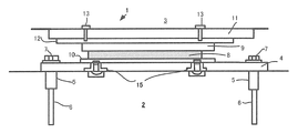
図1、図2は、本発明の構造物用高さ調整支承装置1を橋梁に使用した一実施形態を示す図である。 FIG. 1 and FIG. 2 are views showing an embodiment in which the structure height adjusting support device 1 of the present invention is used for a bridge.
高さ調整支承装置1は、橋脚や橋台等のコンクリート製の下部構造2と橋桁等の上部構造3との間に配置される。コンクリート製の下部構造2上には、ベースプレート4が配置される。下部構造2に埋設されたアンカーボルト6が下部構造2に埋設された雌ねじ部を有する継手部材5に螺着される。ベースプレート4に形成された貫通孔に固定ボルト7が挿入され、固定ボルト7が継手部材5の雌ねじ部に螺着され、ベースプレート4が下部構造2に着脱自在に固定される。
The height adjustment support device 1 is disposed between a concrete
ベースプレート4と上部構造3との間に設置される支承装置はどのような形式の支承装置でも良いが、この実施形態の支承装置は、ベースプレート4上に上下部連結鋼板9、10を有する積層ゴム支承8が配置される。上部構造3に固定されたソールプレート11と上沓12がセットボルト13で固定される。上部連結鋼板9と上沓12とが橋軸方向に可動な状態とする。しかし、上部構造3と下部構造2の間に配置される支承は図に示されたものに限定されるものではなく、他の支承であっても良い。
The bearing device installed between the
ベースプレート4は、 SM490やSC460の鋼材で形成され、その厚さは、支承装置の高さ制限、軽量化の要求により制限される。ベースプレート4の積層ゴム支承8の外側に位置する部分に複数の嵌合穴14が形成される。嵌合穴14は、ベースプレート4の裏面側に開口する下部嵌合穴14aと下部嵌合穴14aと連通し、下部嵌合穴14aより小径でベースプレート4の上面側に開口する上部嵌合穴14bにより構成され、下部嵌合穴14aと上部嵌合穴14bとの間に段部が形成される。下部嵌合穴14aと上部嵌合穴14bの水平切断面の形状はその一部を楕円形、多角形等の非円形の形状とする。
The
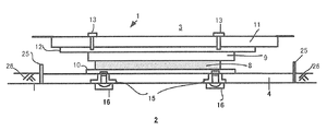
図3、図4は、本発明の構造物用高さ調整支承装置1を橋梁に使用した他の実施形態を示す図である。 3 and 4 are views showing another embodiment in which the structural height adjusting support device 1 of the present invention is used for a bridge.
この実施形態の高さ調整支承装置1は、橋脚や橋台等のコンクリート製の下部構造2と橋桁等の上部構造3との間に配置される。コンクリート製の下部構造2上には、ベースプレート4が配置される。ベースプレート4の周囲にはガイドプレート26が設置され、その周囲に後打ちコンクリート25が打設される。ベースプレート4は、ガイドプレート26に沿って高さ方向の移動が可能であるが、水平方向の移動は拘束される。他の構成は、図1、図2に示される実施形態と同様であるので説明を省略する。
The height adjustment support device 1 of this embodiment is disposed between a concrete
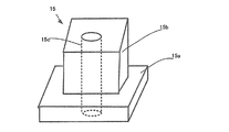
図5、図6は、ベースプレート4の嵌合穴14に嵌合固定される高さ調整雌ねじ部材15を示す図である。高さ調整雌ねじ部材15は、ベースプレート4の下部嵌合穴14aに嵌合する下部15aと、上部嵌合穴14bと嵌合する上部15bを備えている。また、高さ調整雌ねじ部材15は、下部15aと上部15bを貫通する雌ねじ部15cを備えている。高さ調整雌ねじ部材15の下部15aと上部15bの水平切断面の形状は、ベースプレート4に形成された下部嵌合穴14aと上部嵌合穴4bの水平切断面の形状と相似形の形状とし、下部嵌合穴14aと上部嵌合穴4bに嵌合可能とするため嵌合穴より若干小さめとする。高さ調整雌ねじ部材15をベースプレート4の複数の嵌合穴14に嵌合し、溶接等の手段により固定する。ベースプレート4に形成された嵌合穴14と高さ調整雌ねじ部材15の一部の水平切断面の形状を楕円形又は多角形等の非円形とすることで、高さ調整ボルト18の雄ねじ部18aと高さ調整雌ねじ部材15の雌ねじ部15cとの螺着時の回転力に抵抗する。また、高さ調整雌ねじ部材15が下部の水平切断面の面積が上部の水平切断面の面積より大きな嵌合穴14に嵌合固定することで、高さ調整ボルト18による高さ調整時の上昇力に抵抗することが可能になる。
5 and 6 are views showing the height adjusting
高さ調整雌ねじ部材15は、SCMnやS45C等のベースプレート4を形成するSM490やSC460より高強度の材料で形成される。高さ調整雌ねじ部材15をベースプレート4を形成する材料より高強度の材料とすることで、大荷重の支承をジャッキアップさせる際の雌ねじ部15cの強度を確保する。また、高さ調整雌ねじ部材15の雌ねじ部15cを高周波熱処理し、その後クロームメッキを施すことにより、雌ねじ部15cの強度をより向上させると共に、雌ねじ部15cを防錆すると共に、後述する高さ調整ボルト18と雄ねじ部18aとの螺着の際の滑りを良くする。
The height adjusting
図7〜図9は、高さ調整雌ねじ部材15の他の実施形態を示す。図5(a)(b)に示される実施形態は、下部15aの水平切断面の形状が矩形で上部15bの水平切断面の形状が円形の高さ調整雌ねじ部材15を示す。図6(a)(b)に示される実施形態は、下部15aの水平切断面の形状が楕円で上部15bの水平切断面の形状が矩形の高さ調整雌ねじ部材15を示す。図7(a)(b)に示される実施形態は、下部15aの水平切断面の形状が矩形で上部15bの水平切断面の形状も矩形で下部15aと上部15bが段部を形成すること無く、上部が切断された四角錐の形状の高さ調整雌ねじ部材15を示す。
7 to 9 show other embodiments of the height adjusting
図10に示される実施形態では、高さ調整雌ねじ部材15の上部15bをベースプレート4の上面から突き出すようにする。高さ調整雌ねじ部材15の上部15bをベースプレート4の上面から突き出すようにすることで、ベースプレート4の厚さを増加することなく高さ調整のための雌ねじ部15cの雌ねじ長さを確保することが可能となる。また、高さ調整雌ねじ部材15を、防錆を考慮し、SCMnやS45C等より強度の劣るステンレス鋼で形成する場合、高さ調整のための雌ねじ部15cの雌ねじ長さを確保することが可能となる。
In the embodiment shown in FIG. 10, the
高さ調整時以外の期間、高さ調整雌ねじ部材15の雌ねじ部15cの上端に防錆キャップ17を着脱自在に取り付けても良い。防錆キャップ17にゴム製のシールリング21を配置する。シールリング21を水膨張性ゴム製とすると、高さ調整雌ねじ部材15の雌ねじ部15cへの水の浸入を確実に防止することができ、雌ねじ部15cの腐食を防止することが可能になる。
The
高さ調整雌ねじ部材15の雌ねじ部15cの直下の下部構造2に鋼製の反力受け部材
16が埋設設置される。反力受け部材16の高さ調整雌ねじ部材15の雌ねじ部15cの直下の部分は平面或いは球面凹部16aを形成する。反力受け部材16に球面凹部16aを形成することで、高さ調整ボルト18による高さ調整時、高さ調整ボルト18の押圧力による下向きの大荷重が一部に集中するのを防止し、荷重を分散することで反力受け部材16の破壊や下部構造2のコンクリートのひび割れ発生を防止することが可能となる。また、反力受け部材16の球面凹部16aは、高さ調整ボルト18による高さ調整時、高さ調整ボルト18の回転を円滑にすることが可能になる。
A steel reaction
高さ調整時のみ使用される高さ調整ボルト18は、高さ調整雌ねじ部材15と同様に大荷重の支承を上昇させるため高強度の材料で形成され、雄ねじ部18aを高周波熱処理し、その後クロームメッキを施しても良い。
The
図11は、高さ調整雌ねじ部材15の雌ねじ部15cと高さ調整ボルト18の雄ねじ部18aの螺着状態の一実施形態を示す図である。高さ調整雌ねじ部材15の雌ねじ部15cと高さ調整ボルト18の雄ねじ部18aのねじ山を台形とすることで大荷重のジャッキアップが可能となる。しかし、高さ調整雌ねじ部材15の雌ねじ部15cと高さ調整ボルト18の雄ねじ部18aのねじ山の形状はどのようなものであっても良い。
FIG. 11 is a view showing an embodiment of the screwed state of the
図12〜図16は、高さ調整雌ねじ部材15の他の実施形態を示す図である。
12-16 is a figure which shows other embodiment of the height adjustment
この実施形態では、ベースプレート4の側面の下部に接合溝4aを形成する。接合溝4aは、ベースプレート4の4つの側面に形成しても良いし、対向する2つの側面に形成しても良い。また、接合溝4aはベースプレート4の側面の水平方向に沿って所定の長さ形成される。
In this embodiment, the joining
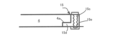
図13に示される高さ調整雌ねじ部材15は、ベースプレート4に形成された接合溝4aに係合する下部水平部15dと、ベースプレート4の側面に当接する垂直部15eと、ベースプレート4の表面と当接する上部水平部15fとからなり、縦方向断面がコ字形をしている。垂直部15eに所定間隔で複数の雌ねじ部15cが形成される。高さ調整雌ねじ部材15は、溶接等の固定手段を介してベースプレート4の側面に固定される。高さ調整雌ねじ部材15をベースプレート4の側面に固定することで、ベースプレート上の他の部材の配置に阻害されることなく複数の雌ねじ部を形成した高さ調整雌ねじ部材を配置することが可能となる。また、高さ調整雌ねじ部材15の縦方向断面をコ字形とし、ベースプレート4の側面を挟み込むようにするので強固に固定することが可能になる。
The height adjusting
図14に示される高さ調整雌ねじ部材15は、図13に示される縦方向断面をコ字形の高さ調整雌ねじ部材15の垂直部15eを上方に突出させる。雌ねじ部が形成される垂直部15eを上方に突出させることで、ベースプレート4の厚さを増加することなく高さ調整のための雌ねじ部15cの雌ねじ長さを確保することが可能となる。
The height adjusting
図15に示される高さ調整雌ねじ部材15は、ベースプレート4の側面の下部に形成された接合溝4aに係合する下部水平部15dと、ベースプレート4の側面に当接する垂直部15eとからなり、縦方向断面がL字形をしている。垂直部15eに所定間隔で複数の雌ねじ部15cが形成される。高さ調整雌ねじ部材15は、溶接等の固定手段を介してベースプレート4の側面に固定される。高さ調整雌ねじ部材15をベースプレート4の側面に固定することで、ベースプレート上の他の部材の配置に阻害されることなく複数の雌ねじ部を形成した高さ調整雌ねじ部材を配置することが可能となる。
The height adjusting
図16に示される高さ調整雌ねじ部材15は、図15に示される縦方向断面をL字形の高さ調整雌ねじ部材15の垂直部15eを上方に突出させる。雌ねじ部が形成される垂直部15eを上方に突出させることで、ベースプレート4の厚さを増加することなく高さ調整のための雌ねじ部15cの雌ねじ長さを確保することが可能となる。
The height adjusting
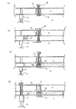
図17(a)〜(d)は、本発明の一実施形態の高さ調整支承装置の高さ調整工法の工程を、時系列に示す図である。 FIGS. 17A to 17D are diagrams showing the steps of the height adjustment method of the height adjustment support device according to the embodiment of the present invention in time series.
図17(a)に示す工程では、下部構造2とベースプレート4を固定している固定ボルト7を取り外し、さらに高さ調整雌ねじ部材15に取り付けられている防錆キャップ17を取り外す。次に、高さ調整ボルト18を高さ調整雌ねじ部材15の雌ねじ部15cに螺着し、高さ調整ボルト18の下端部を下部構造2に埋設設置された反力受け部材16の球面凹部16aに当接させる。
In the step shown in FIG. 17A, the fixing
図17(b)に示す工程では、高さ調整ボルト18を回転させ、ねじ力により反力受け部材16を反力として支承を支持したベースプレート4を上昇させ、ベースプレート4の高さを調整する。ベースプレート4が高さを調整する所定の位置まで上昇すると、下部構造2とベースプレート4との間にライナープレート等を積層した仮支持部材22を設置し、支承の荷重を仮支持部材22で支持するようにする。
In the step shown in FIG. 17B, the
図17(c)に示す工程では、上部構造の荷重を仮支持部材22で支持した状態で、高さ調整ルト18を高さ調整雌ねじ部材15の雌ねじ部15c下部まで上昇させる。この状態で下部構造2と高さ調整雌ねじ部材15の下面との間に反力受けプレート24を設置する。高さ調整雌ねじ部材15と下部構造2との間に反力受けプレート24を設置することで、再度高さ調整が必要になった時、反力受けプレート24を反力受けとして高さ調整が可能となる。その後、仮支持部材22により支持されたベースプレート4と下部構造2との間の空隙にモルタル等の固化性充填材23を充填固化させる。固化性充填材23の固化後、高さ調整ボルト18を引き抜く。
In the step shown in FIG. 17C, the
図17(d)に示す工程では、高さ調整が済んだベースプレート4の貫通孔に固定ボルト7を挿入し、固定ボルト7をアンカーボルト6と螺着された継手部材5に螺着し、ベースプレート4を下部構造2に固定する。高さ調整雌ねじ部材15の雌ねじ部15cに防錆キャップ17を設置する。
In the step shown in FIG. 17D, the fixing
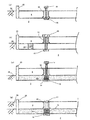
図18(a)〜(d)は、本発明の一実施形態の高さ調整支承装置の高さ調整工法の工程を、時系列に示す図である。 18 (a) to 18 (d) are diagrams showing the steps of the height adjustment method of the height adjustment support device of one embodiment of the present invention in time series.
図18(a)に示す工程では、高さ調整雌ねじ部材15に取り付けられている防錆キャップ17を取り外す。次に、高さ調整ボルト18を高さ調整雌ねじ部材15の雌ねじ部15cに螺着し、高さ調整ボルト18の下端部を下部構造2に埋設設置された反力受け部材16に当接させる。
In the step shown in FIG. 18A, the
図18(b)に示す工程では、高さ調整ボルト18を回転させ、ねじ力により反力受け部材16を反力として支承を支持したベースプレート4を上昇させ、ベースプレート4の高さを調整する。ベースプレート4が高さを調整する所定の位置まで上昇すると、下部構造2とベースプレート4との間にライナープレート等を積層した仮支持部材22を設置し、支承の荷重を仮支持部材22で支持するようにする。
In the step shown in FIG. 18B, the
図18(c)に示す工程では、上部構造の荷重を仮支持部材22で支持した状態で、田高さ調整ルト18を高さ調整雌ねじ部材15の雌ねじ部15c下部まで上昇させる。この状態で下部構造2と高さ調整雌ねじ部材15の下面との間に反力受けプレート24を設置する。高さ調整雌ねじ部材15と下部構造2との間に反力受けプレート24を設置することで、再度高さ調整が必要になった時、反力受けプレート24を反力受けとして高さ調整が可能となる。その後、仮支持部材22により支持されたベースプレート4と下部構造2との間の空隙にモルタル等の固化性充填材23を充填固化させる。固化性充填材23の固化後、高さ調整ボルト18を引き抜く。
In the step shown in FIG. 18C, the field
高さ調整ボルト18を高さ調整雌ねじ部材15から取り外し、仮支持部材22により支持されたベースプレート4と下部構造2との間の空隙にモルタル等の固化性充填材23を充填固化させる。固化性充填材23の固化後、仮支持部材22を撤去しても良いし、そのまま埋め殺しにしても良い。
The
図18(d)に示す工程では、高さ調整が済んだベースプレート4の周囲のガイドプレート5の外側に後打ちコンクリート6を積み増し打設し、高さ調整が済んだベースプレート4の水平方向の移動を拘束する。高さ調整雌ねじ部材15の雌ねじ部15cに防錆キャップ17を設置する。
In the step shown in FIG. 18 (d),
以上のように、本発明の構造物用高さ調整支承装置及び高さ調整工法によれば、高さ調整雌ねじ部材をベースプレートを形成する材料より高強度の材料とすることで、大荷重の支承をジャッキアップさせる際の雌ねじ部の強度を確保することが可能となる。 As described above, according to the height adjustment support device and the height adjustment method for a structure of the present invention, the height adjustment female screw member is made of a material having higher strength than the material forming the base plate, thereby supporting a heavy load. It is possible to ensure the strength of the female screw portion when jacking up the jack.
1:構造物用高さ調整承装置、2:下部構造、3:上部構造、4:ベースプレート、4a:接合溝、5:継手部材、6:アンカーボルト、7:固定ボルト、8:積層ゴム支承、9:上部連結鋼板、10:下部連結鋼板、11:ソールプレート、12:上沓、13:セットボルト、14:嵌合穴、14a:下部嵌合穴、14b:上部嵌合穴、15:高さ調整雌ねじ部材、15a:下部、15b:上部、15c:雌ねじ部、15d:下部水平部、15e:垂直部、15f:上部水平部、16:反力受け部材、16a:球面凹部、17:防錆キャップ、18:高さ調整ボルト、18a:雄ねじ部、21:シールリング、22:仮支持部材、23:固化性充填材、24:反力受けプレート、25:ガイドプレート、26:後打ちコンクリート 1: height adjustment bearing device for structure, 2: lower structure, 3: upper structure, 4: base plate, 4a: joint groove, 5: joint member, 6: anchor bolt, 7: fixing bolt, 8: laminated rubber bearing 9: Upper connecting steel plate, 10: Lower connecting steel plate, 11: Sole plate, 12: Upper rod, 13: Set bolt, 14: Fitting hole, 14a: Lower fitting hole, 14b: Upper fitting hole, 15: Height adjusting female screw member, 15a: lower part, 15b: upper part, 15c: female screw part, 15d: lower horizontal part, 15e: vertical part, 15f: upper horizontal part, 16: reaction force receiving member, 16a: spherical concave part, 17: Rust prevention cap, 18: Height adjusting bolt, 18a: Male thread portion, 21: Seal ring, 22: Temporary support member, 23: Solidifying filler, 24: Reaction force receiving plate, 25: Guide plate, 26: Post-stroke concrete
また、本発明の構造物用高さ調整支承装置は、前記下部構造に前記高さ調整ボルトの下端部と当接する平面、球面状の凹部、ベアリングの内のいずれかの形状とした反力受け部材を埋め込み設置することを特徴とする。 Further, the height adjusting support device for a structure according to the present invention includes a reaction force receiver that has any one of a flat surface, a spherical concave portion, and a bearing that contacts the lower end portion of the height adjusting bolt on the lower structure. A member is embedded and installed.
また、本発明の構造物用支承装置の高さ調整工法は、周囲の後打ちコンクリートで水平方向の移動が拘束されるベースプレートと、前記ベースプレートに複数形成される下部の水平切断面の面積が上部の水平切断面の面積より大きな嵌合穴と、前記嵌合穴と相似形で前記嵌合穴に嵌合固定される前記ベースプレートより高強度の材料で形成され、雌ねじ部を有する高さ調整雌ねじ部材と、高さ調整時、高さ調整雌ねじ部材の雌ねじ部に螺着され、前記下部構造を反力受けとして前記ベースプレートを上昇させる高さ調整ボルトと、を備える構造物用高さ調整支承装置の高さ調整工法であって、高さ調整雌ねじ部材の雌ねじ部に高さ調整ボルトを螺着し、下部構造を反力受けとしてベースプレートを上昇させ高さを調整する工程と、上昇したベースプレートと下部構造との間に仮支持部材を設置する工程と、高さ調整ボルトを上昇させ、ベースプレートの高さ調整雌ねじ部材の下面と下部構造との間に反力受けプレートを設置する工程と、下部構造とベースプレートとの間に固化性充填材を充填する工程と、固化性充填材の固化後、高さ調整ボルトを取り外し、ベースプレートの周囲に後打ちコンクリート打設する工程と、を含むことを特徴とする。
また、本発明の構造物用支承装置の高さ調整工法は、高さ調整ボルトの下端部が当接する反力受けプレートの形状を平面、球面状の凹部、ベアリングの内のいずれかとすることを特徴とする。
Further, the height adjusting method of the structural support device according to the present invention includes a base plate in which horizontal movement is restricted by surrounding post-cast concrete, and an area of a plurality of lower horizontal cut surfaces formed on the base plate is upper. A fitting hole larger than the area of the horizontal cut surface, and a height-adjusting female screw having a female screw part, which is formed of a material that is similar to the fitting hole and is stronger than the base plate that is fitted and fixed to the fitting hole. A height adjustment support device for a structure, comprising: a member, and a height adjustment bolt that is screwed to a female screw portion of the height adjustment female screw member and raises the base plate using the lower structure as a reaction force receiver during height adjustment The height adjustment method includes a step of screwing a height adjustment bolt onto the female thread portion of the height adjustment female screw member, raising the base plate with the lower structure as a reaction force receiver, and adjusting the height. A step of installing a temporary support member between the splate and the lower structure, and a step of raising the height adjustment bolt to install a reaction force receiving plate between the lower surface of the height adjustment female screw member of the base plate and the lower structure. And a step of filling a solidifying filler between the lower structure and the base plate, and a step of removing a height adjusting bolt after the solidifying filler is solidified and placing a post-cast concrete around the base plate. It is characterized by that.
Further, in the height adjustment method of the structural support device of the present invention, the shape of the reaction force receiving plate with which the lower end of the height adjustment bolt abuts is any one of a flat surface, a spherical recess, and a bearing. Features.
高さ調整雌ねじ部材を形成する材料をベースプレートを形成する材料より高強度の材料とすることで、大荷重の支承をジャッキアップさせる際の雌ねじ部の強度を確保することが可能となる。また、高さ調整雌ねじ部材を下部の水平切断面の面積が上部の水平切断面の面積より大きく形成することで、高さ調整ボルトの回転に伴う上昇力に抵抗することが可能になる。
高さ調整雌ねじ部材の一部の水平切断面の形状を非円形とすることで、高さ調整ボルトの回転力に抵抗することが可能になる。
ベースプレートの側面に固定されるベースプレートより高強度の材料で形成され、ベースプレートの下部側面に形成された接合溝に係合する下部水平部とベースプレートの側面に当接する垂直部とを少なくとも有し、ベースプレートの側面に沿って水平に延び、垂直部に複数の雌ねじ部を形成した高さ調整雌ねじ部材とすることで、ベースプレート上の他の部材の配置に阻害されることなく複数の雌ねじ部を形成した高さ調整雌ねじ部材を配置することが可能となる。
高さ調整雌ねじ部材を前記接合溝に係合する下部水平部と前記ベースプレートの側面と当接する垂直部と前記ベースプレート表面と当接する上部水平部とを有するようにすることで、高さ調整雌ねじ部材をベースプレートの側面に強固に固定することが可能となる。
高さ調整雌ねじ部材の上部又は垂直部を前記ベースプレートの表面から上方に突き出させることで、ベースプレートの厚さ増加すること無く、ジャッキアップのための雌ねじ長さを確保することが可能になる。
高さ調整雌ねじ部材の不使用時、防錆キャップを設置することで、高さ調整雌ねじ部材の雌ねじ部への水や塵の浸入を防止し、雌ねじ部の腐食を防止することが可能になる。
下部構造に高さ調整ボルトの下端部と当接する平面、球面状の凹部、ベアリングの内のいずれかの形状とした反力受け部材を埋め込み設置することで、高さ調整ボルトによるジャッキアップ荷重による下部構造のひび割れ等を防止し、球面状の凹部を形成することで、集中荷重を防止することが可能になり、さらに、高さ調整ボルトの回転抵抗を低減することが可能となる。また、反力受け部材をベアリングとすること、高さ調整ボルトの回転抵抗をより低減し、下部構造への影響を低減することが可能になる。
ベースプレートの周囲と後打ちコンクリートとの間にガイドプレートを設置し、前記ベースプレートを前記ガイドプレートに沿って上下動可能とすることで、ベースプレートの高さ調整が容易に実施することが可能となる。
上記の構造物用高さ調整支承装置の高さ調整工法であって、ベースプレートを固定している固定ボルトを解除する工程と、高さ調整雌ねじ部材の雌ねじ部に高さ調整ボルトを螺着し、下部構造を反力受けとしてベースプレートを上昇させ高さを調整する工程と、上昇したベースプレートと下部構造との間に仮支持部材を設置する工程と、高さ調整ボルトを上昇させベースプレートの高さ調整雌ねじ部材の下面と下部構造との間に反力受けプレートを設置する工程と、下部構造とベースプレートとの間に固化性充填材を充填する工程と、固化性充填材の固化後、高さ調整ボルトを取り外し、ベースプレートを固定ボルトで下部構造に固定する工程と、を含むことで、大荷重の支承をジャッキアップさせる際の雌ねじ部の強度を確保して確実に支承装置の高さ調整することが可能となる。
また、高さ調整ボルトの下端部が当接する反力受けプレートの形状を平面、球面状の凹部、ベアリングの内のいずれかとすることで、球面状の凹部の形状で集中荷重を防止し、高さ調整ボルトの回転抵抗を低減することが可能となる。また、反力受けプレートをベアリングとすること、高さ調整ボルトの回転抵抗をより低減し、下部構造への影響を低減することが可能になる。
By making the material for forming the height adjusting female screw member a material having higher strength than the material for forming the base plate, it is possible to ensure the strength of the female screw portion when jacking up a heavy load support. In addition, by forming the height adjusting female screw member so that the area of the lower horizontal cutting surface is larger than the area of the upper horizontal cutting surface, it is possible to resist the ascending force accompanying the rotation of the height adjusting bolt.
It is possible to resist the rotational force of the height adjustment bolt by making the shape of the horizontal cut surface of a part of the height adjustment female screw member non-circular.
The base plate is formed of a material stronger than the base plate fixed to the side surface of the base plate, and has at least a lower horizontal portion that engages with a joining groove formed on the lower side surface of the base plate and a vertical portion that abuts the side surface of the base plate. By forming a height-adjusting female screw member that extends horizontally along the side surface of the base plate and has a plurality of female screw portions formed in the vertical portion, a plurality of female screw portions are formed without being obstructed by the arrangement of other members on the base plate. It becomes possible to arrange a height adjusting female screw member.
The height adjusting female screw member has a lower horizontal part that engages with the joining groove, a vertical part that comes into contact with the side surface of the base plate, and an upper horizontal part that comes into contact with the surface of the base plate. Can be firmly fixed to the side surface of the base plate.
By projecting the upper part or vertical part of the height adjusting female screw member upward from the surface of the base plate, it is possible to ensure the length of the female screw for jacking up without increasing the thickness of the base plate.
By installing a rust prevention cap when the height adjustment female thread member is not used, water and dust can be prevented from entering the female thread part of the height adjustment female thread member, and corrosion of the female thread part can be prevented. .
By embedding and installing a reaction force receiving member in the shape of one of the flat surface, spherical recess, or bearing that contacts the lower end of the height adjustment bolt in the lower structure, due to the jack-up load by the height adjustment bolt By preventing cracks and the like of the lower structure and forming the spherical concave portion, it is possible to prevent concentrated load and further reduce the rotational resistance of the height adjusting bolt. Further, the reaction force receiving member can be a bearing, the rotational resistance of the height adjusting bolt can be further reduced, and the influence on the lower structure can be reduced.
By installing a guide plate between the periphery of the base plate and the post-cast concrete and allowing the base plate to move up and down along the guide plate, the height of the base plate can be easily adjusted.
A height adjustment method for the above-described height adjustment support device for a structure, the step of releasing the fixing bolt fixing the base plate, and screwing the height adjustment bolt onto the female screw portion of the height adjusting female screw member The process of adjusting the height by raising the base plate using the lower structure as a reaction force receiver, the process of installing a temporary support member between the raised base plate and the lower structure, and the height of the base plate by raising the height adjustment bolt The step of installing the reaction force receiving plate between the lower surface of the adjusting female screw member and the lower structure, the step of filling the solidifying filler between the lower structure and the base plate, and the height after the solidifying filler is solidified Removing the adjustment bolt and fixing the base plate to the lower structure with the fixing bolt, ensuring the strength of the female thread when jacking up a heavy load bearing and supporting it securely. It becomes possible to adjust the height of the device.
In addition, the shape of the reaction force receiving plate with which the lower end of the height adjustment bolt abuts is either a flat surface, a spherical concave portion, or a bearing, thereby preventing concentrated loads due to the spherical concave shape. It becomes possible to reduce the rotational resistance of the height adjusting bolt. Further, the reaction force receiving plate can be a bearing, the rotational resistance of the height adjusting bolt can be further reduced, and the influence on the lower structure can be reduced.
高さ調整雌ねじ部材15の雌ねじ部15cの直下の下部構造2に鋼製の反力受け部材
16が埋設設置される。反力受け部材16の高さ調整雌ねじ部材15の雌ねじ部15cの直下の部分は平面或いは球面凹部16aを形成する。反力受け部材16に球面凹部16aを形成することで、高さ調整ボルト18による高さ調整時、高さ調整ボルト18の押圧力による下向きの大荷重が一部に集中するのを防止し、荷重を分散することで反力受け部材16の破壊や下部構造2のコンクリートのひび割れ発生を防止することが可能となる。また、反力受け部材16の球面凹部16aは、高さ調整ボルト18による高さ調整時、高さ調整ボルト18の回転を円滑にすることが可能になる。図19に示すように、反力受け部材16をベアリングけ16bとしても良い。反力受け部材をベアリングけ16bとすることで、高さ調整ボルト18による高さ調整時、高さ調整ボルト18の回転をより円滑にし、下部構造2への影響を低減することが可能になる。
A steel reaction
図17(c)に示す工程では、上部構造の荷重を仮支持部材22で支持した状態で、高さ調整ルト18を高さ調整雌ねじ部材15の雌ねじ部15c下部まで上昇させる。この状態で下部構造2と高さ調整雌ねじ部材15の下面との間に反力受けプレート24を設置する。高さ調整雌ねじ部材15と下部構造2との間に反力受けプレート24を設置することで、再度高さ調整が必要になった時、反力受けプレート24を反力受けとして高さ調整が可能となる。反力受けプレート24の形状は、反力受け部材16と同様に、平面、球面状の凹部、ベアリング24aの内のいずれかとする。図20に反力受けプレート24としてベアリング24aを用いた例を示す。反力受けプレート24としてベアリング24を用いる場合、高さ調整が済んだ高さ調整ボルト18の下端にベアリング24aを支持させておく。その後、仮支持部材22により支持されたベースプレート4と下部構造2との間の空隙にモルタル等の固化性充填材23を充填固化させる。固化性充填材23の固化後、高さ調整ボルト18を引き抜く。
In the step shown in FIG. 17C, the
図18(c)に示す工程では、上部構造の荷重を仮支持部材22で支持した状態で、田高さ調整ルト18を高さ調整雌ねじ部材15の雌ねじ部15c下部まで上昇させる。この状態で下部構造2と高さ調整雌ねじ部材15の下面との間に反力受けプレート24を設置する。高さ調整雌ねじ部材15と下部構造2との間に反力受けプレート24を設置することで、再度高さ調整が必要になった時、反力受けプレート24を反力受けとして高さ調整が可能となる。反力受けプレート24の形状は、反力受け部材16と同様に、平面、球面状の凹部、ベアリング24aの内のいずれかとする。図20に反力受けプレート24としてベアリング24aを用いた例を示す。反力受けプレート24としてベアリング24を用いる場合、高さ調整が済んだ高さ調整ボルト18の下端にベアリング24aを支持させておく。その後、仮支持部材22により支持されたベースプレート4と下部構造2との間の空隙にモルタル等の固化性充填材23を充填固化させる。固化性充填材23の固化後、高さ調整ボルト18を引き抜く。
In the step shown in FIG. 18C, the field
1:構造物用高さ調整承装置、2:下部構造、3:上部構造、4:ベースプレート、4a:接合溝、5:継手部材、6:アンカーボルト、7:固定ボルト、8:積層ゴム支承、9:上部連結鋼板、10:下部連結鋼板、11:ソールプレート、12:上沓、13:セットボルト、14:嵌合穴、14a:下部嵌合穴、14b:上部嵌合穴、15:高さ調整雌ねじ部材、15a:下部、15b:上部、15c:雌ねじ部、15d:下部水平部、15e:垂直部、15f:上部水平部、16:反力受け部材、16a:球面凹部、16b:ベアリング、17:防錆キャップ、18:高さ調整ボルト、18a:雄ねじ部、21:シールリング、22:仮支持部材、23:固化性充填材、24:反力受けプレート、24a:ベアリング、25:ガイドプレート、26:後打ちコンクリート 1: height adjustment bearing device for structure, 2: lower structure, 3: upper structure, 4: base plate, 4a: joint groove, 5: joint member, 6: anchor bolt, 7: fixing bolt, 8: laminated rubber bearing 9: Upper connecting steel plate, 10: Lower connecting steel plate, 11: Sole plate, 12: Upper rod, 13: Set bolt, 14: Fitting hole, 14a: Lower fitting hole, 14b: Upper fitting hole, 15: Height adjustment female screw member, 15a: lower part, 15b: upper part, 15c: female screw part, 15d: lower horizontal part, 15e: vertical part, 15f: upper horizontal part, 16: reaction force receiving member, 16a: spherical concave part, 16b: Bearing : 17: Rust prevention cap, 18: Height adjusting bolt, 18a: Male thread portion, 21: Seal ring, 22: Temporary support member, 23: Solidifying filler, 24: Reaction force receiving plate, 24a: Bearing, 25 :guide Plate, 26: Post-cast concrete
また、本発明の構造物用支承装置の高さ調整工法は、周囲の後打ちコンクリートで水平方向の移動が拘束されるベースプレートと、前記ベースプレートに複数形成される下部の水平切断面の面積が上部の水平切断面の面積より大きな嵌合穴と、前記嵌合穴と相似形で前記嵌合穴に嵌合固定される前記ベースプレートより高強度の材料で形成され、雌ねじ部を有する高さ調整雌ねじ部材と、高さ調整時、高さ調整雌ねじ部材の雌ねじ部に螺着され、前記下部構造を反力受けとして前記ベースプレートを上昇させる高さ調整ボルトと、を備える構造物用高さ調整支承装置の高さ調整工法であって、高さ調整雌ねじ部材の雌ねじ部に高さ調整ボルトを螺着し、下部構造を反力受けとしてベースプレートを上昇させ高さを調整する工程と、上昇したベースプレートと下部構造との間に仮支持部材を設置する工程と、高さ調整ボルトを上昇させ、ベースプレートの高さ調整雌ねじ部材の下面と下部構造との間に反力受けプレートを設置する工程と、下部構造とベースプレートとの間に固化性充填材を充填する工程と、固化性充填材の固化後、高さ調整ボルトを取り外し、ベースプレートの周囲に後打ちコンクリート打設する工程と、を含むことを特徴とする。 Further, the height adjusting method of the structural support device according to the present invention includes a base plate in which horizontal movement is restricted by surrounding post-cast concrete, and an area of a plurality of lower horizontal cut surfaces formed on the base plate is upper. A fitting hole larger than the area of the horizontal cut surface, and a height-adjusting female screw having a female screw part, which is formed of a material that is similar to the fitting hole and is stronger than the base plate that is fitted and fixed to the fitting hole. A height adjustment support device for a structure, comprising: a member, and a height adjustment bolt that is screwed to a female screw portion of the height adjustment female screw member and raises the base plate using the lower structure as a reaction force receiver during height adjustment The height adjustment method includes a step of screwing a height adjustment bolt onto the female thread portion of the height adjustment female screw member, raising the base plate with the lower structure as a reaction force receiver, and adjusting the height. A step of installing a temporary support member between the splate and the lower structure, and a step of raising the height adjustment bolt to install a reaction force receiving plate between the lower surface of the height adjustment female screw member of the base plate and the lower structure. And a step of filling a solidifying filler between the lower structure and the base plate, and a step of removing a height adjusting bolt after the solidifying filler is solidified and placing a post-cast concrete around the base plate. It is characterized by that.
高さ調整雌ねじ部材を形成する材料をベースプレートを形成する材料より高強度の材料とすることで、大荷重の支承をジャッキアップさせる際の雌ねじ部の強度を確保することが可能となる。また、高さ調整雌ねじ部材を下部の水平切断面の面積が上部の水平切断面の面積より大きく形成することで、高さ調整ボルトの回転に伴う上昇力に抵抗することが可能になる。
高さ調整雌ねじ部材の一部の水平切断面の形状を非円形とすることで、高さ調整ボルトの回転力に抵抗することが可能になる。
ベースプレートの側面に固定されるベースプレートより高強度の材料で形成され、ベースプレートの下部側面に形成された接合溝に係合する下部水平部とベースプレートの側面に当接する垂直部とを少なくとも有し、ベースプレートの側面に沿って水平に延び、垂直部に複数の雌ねじ部を形成した高さ調整雌ねじ部材とすることで、ベースプレート上の他の部材の配置に阻害されることなく複数の雌ねじ部を形成した高さ調整雌ねじ部材を配置することが可能となる。
高さ調整雌ねじ部材を前記接合溝に係合する下部水平部と前記ベースプレートの側面と当接する垂直部と前記ベースプレート表面と当接する上部水平部とを有するようにすることで、高さ調整雌ねじ部材をベースプレートの側面に強固に固定することが可能となる。
高さ調整雌ねじ部材の上部又は垂直部を前記ベースプレートの表面から上方に突き出させることで、ベースプレートの厚さ増加すること無く、ジャッキアップのための雌ねじ長さを確保することが可能になる。
高さ調整雌ねじ部材の不使用時、防錆キャップを設置することで、高さ調整雌ねじ部材の雌ねじ部への水や塵の浸入を防止し、雌ねじ部の腐食を防止することが可能になる。
ベースプレートの周囲と後打ちコンクリートとの間にガイドプレートを設置し、前記ベースプレートを前記ガイドプレートに沿って上下動可能とすることで、ベースプレートの高さ調整が容易に実施することが可能となる。
上記の構造物用高さ調整支承装置の高さ調整工法であって、ベースプレートを固定している固定ボルトを解除する工程と、高さ調整雌ねじ部材の雌ねじ部に高さ調整ボルトを螺着し、下部構造を反力受けとしてベースプレートを上昇させ高さを調整する工程と、上昇したベースプレートと下部構造との間に仮支持部材を設置する工程と、高さ調整ボルトを上昇させベースプレートの高さ調整雌ねじ部材の下面と下部構造との間に反力受けプレートを設置する工程と、下部構造とベースプレートとの間に固化性充填材を充填する工程と、固化性充填材の固化後、高さ調整ボルトを取り外し、ベースプレートを固定ボルトで下部構造に固定する工程と、を含むことで、大荷重の支承をジャッキアップさせる際の雌ねじ部の強度を確保して確実に支承装置の高さ調整することが可能となる。
By making the material for forming the height adjusting female screw member a material having higher strength than the material for forming the base plate, it is possible to ensure the strength of the female screw portion when jacking up a heavy load support. In addition, by forming the height adjusting female screw member so that the area of the lower horizontal cutting surface is larger than the area of the upper horizontal cutting surface, it is possible to resist the ascending force accompanying the rotation of the height adjusting bolt.
It is possible to resist the rotational force of the height adjustment bolt by making the shape of the horizontal cut surface of a part of the height adjustment female screw member non-circular.
The base plate is formed of a material stronger than the base plate fixed to the side surface of the base plate, and has at least a lower horizontal portion that engages with a joining groove formed on the lower side surface of the base plate and a vertical portion that abuts the side surface of the base plate. By forming a height-adjusting female screw member that extends horizontally along the side surface of the base plate and has a plurality of female screw portions formed in the vertical portion, a plurality of female screw portions are formed without being obstructed by the arrangement of other members on the base plate. It becomes possible to arrange a height adjusting female screw member.
The height adjusting female screw member has a lower horizontal part that engages with the joining groove, a vertical part that comes into contact with the side surface of the base plate, and an upper horizontal part that comes into contact with the surface of the base plate. Can be firmly fixed to the side surface of the base plate.
By projecting the upper part or vertical part of the height adjusting female screw member upward from the surface of the base plate, it is possible to ensure the length of the female screw for jacking up without increasing the thickness of the base plate.
By installing a rust prevention cap when the height adjustment female thread member is not used, water and dust can be prevented from entering the female thread part of the height adjustment female thread member, and corrosion of the female thread part can be prevented. .
By installing a guide plate between the periphery of the base plate and the post-cast concrete and allowing the base plate to move up and down along the guide plate, the height of the base plate can be easily adjusted.
A height adjustment method for the above-described height adjustment support device for a structure, the step of releasing the fixing bolt fixing the base plate, and screwing the height adjustment bolt onto the female screw portion of the height adjusting female screw member The process of adjusting the height by raising the base plate using the lower structure as a reaction force receiver, the process of installing a temporary support member between the raised base plate and the lower structure, and the height of the base plate by raising the height adjustment bolt The step of installing the reaction force receiving plate between the lower surface of the adjusting female screw member and the lower structure, the step of filling the solidifying filler between the lower structure and the base plate, and the height after the solidifying filler is solidified Removing the adjustment bolt and fixing the base plate to the lower structure with the fixing bolt, ensuring the strength of the female thread when jacking up a heavy load bearing and supporting it securely. It becomes possible to adjust the height of the device.
高さ調整雌ねじ部材15の雌ねじ部15cの直下の下部構造2に鋼製の反力受け部材
16が埋設設置される。反力受け部材16の高さ調整雌ねじ部材15の雌ねじ部15cの直下の部分は平面或いは球面凹部16aを形成する。反力受け部材16に球面凹部16aを形成することで、高さ調整ボルト18による高さ調整時、高さ調整ボルト18の押圧力による下向きの大荷重が一部に集中するのを防止し、荷重を分散することで反力受け部材16の破壊や下部構造2のコンクリートのひび割れ発生を防止することが可能となる。また、反力受け部材16の球面凹部16aは、高さ調整ボルト18による高さ調整時、高さ調整ボルト18の回転を円滑にすることが可能になる。
A steel reaction
図17(c)に示す工程では、上部構造の荷重を仮支持部材22で支持した状態で、高さ調整ルト18を高さ調整雌ねじ部材15の雌ねじ部15c下部まで上昇させる。この状態で下部構造2と高さ調整雌ねじ部材15の下面との間に反力受けプレート24を設置する。高さ調整雌ねじ部材15と下部構造2との間に反力受けプレート24を設置することで、再度高さ調整が必要になった時、反力受けプレート24を反力受けとして高さ調整が可能となる。その後、仮支持部材22により支持されたベースプレート4と下部構造2との間の空隙にモルタル等の固化性充填材23を充填固化させる。固化性充填材23の固化後、高さ調整ボルト18を引き抜く。
In the step shown in FIG. 17C, the
図18(c)に示す工程では、上部構造の荷重を仮支持部材22で支持した状態で、田高さ調整ルト18を高さ調整雌ねじ部材15の雌ねじ部15c下部まで上昇させる。この状態で下部構造2と高さ調整雌ねじ部材15の下面との間に反力受けプレート24を設置する。高さ調整雌ねじ部材15と下部構造2との間に反力受けプレート24を設置することで、再度高さ調整が必要になった時、反力受けプレート24を反力受けとして高さ調整が可能となる。その後、仮支持部材22により支持されたベースプレート4と下部構造2との間の空隙にモルタル等の固化性充填材23を充填固化させる。固化性充填材23の固化後、高さ調整ボルト18を引き抜く。
In the step shown in FIG. 18C, the field
1:構造物用高さ調整承装置、2:下部構造、3:上部構造、4:ベースプレート、4a:接合溝、5:継手部材、6:アンカーボルト、7:固定ボルト、8:積層ゴム支承、9:上部連結鋼板、10:下部連結鋼板、11:ソールプレート、12:上沓、13:セットボルト、14:嵌合穴、14a:下部嵌合穴、14b:上部嵌合穴、15:高さ調整雌ねじ部材、15a:下部、15b:上部、15c:雌ねじ部、15d:下部水平部、15e:垂直部、15f:上部水平部、16:反力受け部材、16a:球面凹部、17:防錆キャップ、18:高さ調整ボルト、18a:雄ねじ部、21:シールリング、22:仮支持部材、23:固化性充填材、24:反力受けプレート、25:ガイドプレート、26:後打ちコンクリート 1: height adjustment bearing device for structure, 2: lower structure, 3: upper structure, 4: base plate, 4a: joint groove, 5: joint member, 6: anchor bolt, 7: fixing bolt, 8: laminated rubber bearing 9: Upper connecting steel plate, 10: Lower connecting steel plate, 11: Sole plate, 12: Upper rod, 13: Set bolt, 14: Fitting hole, 14a: Lower fitting hole, 14b: Upper fitting hole, 15: Height adjusting female screw member, 15a: lower part, 15b: upper part, 15c: female screw part, 15d: lower horizontal part, 15e: vertical part, 15f: upper horizontal part, 16: reaction force receiving member, 16a: spherical concave part, 17: Rust prevention cap, 18: Height adjusting bolt, 18a: Male thread portion, 21: Seal ring, 22: Temporary support member, 23: Solidifying filler, 24: Reaction force receiving plate, 25: Guide plate, 26: Post-stroke concrete
Claims (11)
下部構造に固定ボルトにより着脱自在に固定されるベースプレートと、
前記ベースプレートに複数形成される下部の水平切断面の面積が上部の水平切断面の面積より大きな嵌合穴と、
前記嵌合穴と相似形で前記嵌合穴に嵌合固定される前記ベースプレートより高強度の材料で形成され、雌ねじ部を有する高さ調整雌ねじ部材と、
高さ調整時、固定ボルトによる下部構造との固定を解除されたベースプレートの高さ調整雌ねじ部材の雌ねじ部に螺着され、前記下部構造を反力受けとして前記ベースプレートを上昇させる高さ調整ボルトと、
を備えることを特徴とする構造物用高さ調整支承装置。 A support device for a structure disposed between a lower structure and an upper structure,
A base plate that is detachably fixed to the lower structure by fixing bolts;
A plurality of fitting holes in which the area of the lower horizontal cutting surface formed in the base plate is larger than the area of the upper horizontal cutting surface;
A height-adjusting female screw member that is formed of a material that is similar to the fitting hole and has a higher strength than the base plate that is fitted and fixed to the fitting hole;
A height adjustment bolt that is screwed into the female thread portion of the height adjustment female screw member of the base plate that is released from being fixed to the lower structure by the fixing bolt during height adjustment, and raises the base plate using the lower structure as a reaction force receiver; ,
A height-adjusting support device for a structure, comprising:
周囲の後打ちコンクリートで水平方向の移動が拘束されるベースプレートと、
前記ベースプレートに複数形成される下部の水平切断面の面積が上部の水平切断面の面積より大きな嵌合穴と、
前記嵌合穴と相似形で前記嵌合穴に嵌合固定される前記ベースプレートより高強度の材料で形成され、雌ねじ部を有する高さ調整雌ねじ部材と、
高さ調整時、高さ調整雌ねじ部材の雌ねじ部に螺着され、前記下部構造を反力受けとして前記ベースプレートを上昇させる高さ調整ボルトと、
を備えることを特徴とする構造物用高さ調整支承装置。 A support device for a structure disposed between a lower structure and an upper structure,
A base plate whose horizontal movement is restrained by the surrounding concrete afterwards,
A plurality of fitting holes in which the area of the lower horizontal cutting surface formed in the base plate is larger than the area of the upper horizontal cutting surface;
A height-adjusting female screw member that is formed of a material that is similar to the fitting hole and has a higher strength than the base plate that is fitted and fixed to the fitting hole;
At the time of height adjustment, a height adjustment bolt that is screwed into the female screw portion of the height adjustment female screw member and raises the base plate using the lower structure as a reaction force receiver,
A height-adjusting support device for a structure, comprising:
下部構造に固定ボルトにより着脱自在に固定されるベースプレートと、
前記ベースプレートの側面の下部に形成される接合溝と、
前記ベースプレートの側面に固定される前記ベースプレートより高強度の材料で形成され、前記接合溝に係合する下部水平部と前記ベースプレートの側面に当接する垂直部とを少なくとも有し、前記ベースプレートの側面に沿って水平に延び、前記垂直部に複数の雌ねじ部を形成した高さ調整雌ねじ部材と、
高さ調整時、固定ボルトによる下部構造との固定を解除されたベースプレートの高さ調整雌ねじ部材の雌ねじ部に螺着され、前記下部構造を反力受けとして前記ベースプレートを上昇させる高さ調整ボルトと、
を備えることを特徴とする構造物用高さ調整支承装置。 A support device for a structure disposed between a lower structure and an upper structure,
A base plate that is detachably fixed to the lower structure by fixing bolts;
A bonding groove formed in a lower portion of a side surface of the base plate;
The base plate is formed of a material stronger than the base plate fixed to the side surface of the base plate, and has at least a lower horizontal portion that engages with the joining groove and a vertical portion that abuts the side surface of the base plate, A height adjusting female screw member extending horizontally along the vertical part and forming a plurality of female screw parts on the vertical part;
A height adjustment bolt that is screwed into the female thread portion of the height adjustment female screw member of the base plate that is released from being fixed to the lower structure by the fixing bolt during height adjustment, and raises the base plate using the lower structure as a reaction force receiver; ,
A height-adjusting support device for a structure, comprising:
ベースプレートを固定している固定ボルトを解除する工程と、
高さ調整雌ねじ部材の雌ねじ部に高さ調整ボルトを螺着し、下部構造を反力受けとしてベースプレートを上昇させ高さを調整する工程と、
上昇したベースプレートと下部構造との間に仮支持部材を設置する工程と、
高さ調整ボルトを上昇させベースプレートの高さ調整雌ねじ部材の下面と下部構造との間に反力受けプレートを設置する工程と、
下部構造とベースプレートとの間に固化性充填材を充填する工程と、
固化性充填材の固化後、高さ調整ボルトを取り外し、ベースプレートを固定ボルトで下部構造に固定する工程と、
を含むことを特徴とする構造物支承装置の高さ調整工法。 A base plate that is detachably fixed to the lower structure with fixing bolts, a fitting hole in which a plurality of lower horizontal cutting surfaces formed on the base plate have an area larger than that of the upper horizontal cutting surface, and similar to the fitting hole The height adjustment female screw member having a female screw part formed of a material stronger than the base plate fitted and fixed in the fitting hole in the form and the lower structure by the fixing bolt is released when the height is adjusted. A height adjustment method for a structure height adjustment support device, comprising: a height adjustment bolt that is screwed into a female thread portion of a height adjustment female thread member of the base plate and raises the base plate using the lower structure as a reaction force receiver. Because
Releasing the fixing bolts fixing the base plate;
A step of screwing a height adjustment bolt onto the female screw portion of the height adjustment female screw member and adjusting the height by raising the base plate using the lower structure as a reaction force receiver;
Installing a temporary support member between the raised base plate and the lower structure;
Raising the height adjustment bolt and installing a reaction force receiving plate between the lower surface of the height adjustment female screw member of the base plate and the lower structure;
Filling a solidifying filler between the substructure and the base plate;
After solidifying the solidifying filler, removing the height adjustment bolt and fixing the base plate to the lower structure with a fixing bolt;
A method for adjusting the height of a structure support device, comprising:
高さ調整雌ねじ部材の雌ねじ部に高さ調整ボルトを螺着し、下部構造を反力受けとしてベースプレートを上昇させ高さを調整する工程と、
上昇したベースプレートと下部構造との間に仮支持部材を設置する工程と、
高さ調整ボルトを上昇させ、ベースプレートの高さ調整雌ねじ部材の下面と下部構造との間に反力受けプレートを設置する工程と、
下部構造とベースプレートとの間に固化性充填材を充填する工程と、
固化性充填材の固化後、高さ調整ボルトを取り外し、ベースプレートの周囲に後打ちコンクリート打設する工程と、
を含むことを特徴とする構造物支承装置の高さ調整工法。 A base plate whose horizontal movement is constrained by surrounding post-cast concrete, a fitting hole in which a plurality of lower horizontal cutting surfaces formed on the base plate have a larger area than an upper horizontal cutting surface, and the fitting hole A height-adjusting female screw member that has a female thread portion and is formed of a material stronger than the base plate that is fitted and fixed in the fitting hole in a similar shape to the female screw portion of the height-adjusting female screw member during height adjustment. A height adjustment method for a height adjustment support device for a structure, comprising: a height adjustment bolt that is screwed and raises the base plate using the lower structure as a reaction force receiver,
A step of screwing a height adjustment bolt onto the female screw portion of the height adjustment female screw member and adjusting the height by raising the base plate using the lower structure as a reaction force receiver;
Installing a temporary support member between the raised base plate and the lower structure;
Raising the height adjustment bolt and installing a reaction force receiving plate between the lower surface of the height adjustment female screw member of the base plate and the lower structure;
Filling a solidifying filler between the substructure and the base plate;
After solidifying the solidifying filler, removing the height adjusting bolt and placing the post-cast concrete around the base plate;
A method for adjusting the height of a structure support device, comprising:
Priority Applications (1)
| Application Number | Priority Date | Filing Date | Title |
|---|---|---|---|
| JP2010254399A JP4702862B1 (en) | 2010-11-15 | 2010-11-15 | Height adjustment support device for structure and height adjustment method for structure support device |
Applications Claiming Priority (1)
| Application Number | Priority Date | Filing Date | Title |
|---|---|---|---|
| JP2010254399A JP4702862B1 (en) | 2010-11-15 | 2010-11-15 | Height adjustment support device for structure and height adjustment method for structure support device |
Publications (2)
| Publication Number | Publication Date |
|---|---|
| JP4702862B1 JP4702862B1 (en) | 2011-06-15 |
| JP2012102601A true JP2012102601A (en) | 2012-05-31 |
Family
ID=44237092
Family Applications (1)
| Application Number | Title | Priority Date | Filing Date |
|---|---|---|---|
| JP2010254399A Expired - Fee Related JP4702862B1 (en) | 2010-11-15 | 2010-11-15 | Height adjustment support device for structure and height adjustment method for structure support device |
Country Status (1)
| Country | Link |
|---|---|
| JP (1) | JP4702862B1 (en) |
Cited By (2)
| Publication number | Priority date | Publication date | Assignee | Title |
|---|---|---|---|---|
| CN108103941A (en) * | 2017-12-19 | 2018-06-01 | 雨发建设集团有限公司 | A kind of corrugated tetrafluoro plate rubber bearing unidirectionally constrains precast beam installation method |
| CN111172861A (en) * | 2020-03-04 | 2020-05-19 | 王少鹏 | High-speed bridge with bearing deformation structure |
Families Citing this family (10)
| Publication number | Priority date | Publication date | Assignee | Title |
|---|---|---|---|---|
| CN103306210B (en) * | 2013-07-05 | 2016-04-06 | 河北工业大学 | The lip block that a kind of Bridge Erector front height is adjustable |
| CN106120564B (en) * | 2016-08-16 | 2017-11-03 | 中国建筑土木建设有限公司 | Bidirectional unloading type height-adjusting drop frame and continuous beam temporary supporting method |
| CN108581508A (en) * | 2018-05-22 | 2018-09-28 | 苏州市传福精密机械有限公司 | A kind of height adjusting device for bottom studs of numerical-control machine tools |
| CN109914268B (en) * | 2019-04-23 | 2024-06-04 | 五冶集团上海有限公司 | Adjustable unloading device for mounting precast beam plates |
| CN110173279A (en) * | 2019-05-30 | 2019-08-27 | 平顶山平煤机煤矿机械装备有限公司 | A kind of tunnel lining trolley adjusts the device of sealing plate height |
| CN112503060B (en) * | 2020-11-27 | 2022-10-25 | 浙江盈亿机械股份有限公司 | Oil temperature constant-temperature intelligent control system and installation method thereof |
| CN113982265A (en) * | 2021-10-25 | 2022-01-28 | 中国建筑第八工程局有限公司 | Friction self-locking type die carrier support |
| CN114164769B (en) * | 2021-12-28 | 2023-04-14 | 招商局重庆交通科研设计院有限公司 | Temporary support for bridge construction |
| CN114622484A (en) * | 2022-04-25 | 2022-06-14 | 中铁大桥局集团有限公司 | Multifunctional intelligent support and use method |
| CN115231278B (en) * | 2022-09-22 | 2022-12-20 | 中南大学 | Fastener conveying mechanism and support height adjusting system |
-
2010
- 2010-11-15 JP JP2010254399A patent/JP4702862B1/en not_active Expired - Fee Related
Cited By (3)
| Publication number | Priority date | Publication date | Assignee | Title |
|---|---|---|---|---|
| CN108103941A (en) * | 2017-12-19 | 2018-06-01 | 雨发建设集团有限公司 | A kind of corrugated tetrafluoro plate rubber bearing unidirectionally constrains precast beam installation method |
| CN108103941B (en) * | 2017-12-19 | 2019-09-20 | 雨发建设集团有限公司 | A kind of corrugated tetrafluoro plate rubber support unidirectionally constrains precast beam installation method |
| CN111172861A (en) * | 2020-03-04 | 2020-05-19 | 王少鹏 | High-speed bridge with bearing deformation structure |
Also Published As
| Publication number | Publication date |
|---|---|
| JP4702862B1 (en) | 2011-06-15 |
Similar Documents
| Publication | Publication Date | Title |
|---|---|---|
| JP4702862B1 (en) | Height adjustment support device for structure and height adjustment method for structure support device | |
| KR100948359B1 (en) | The bridge upper structure lifting method for which bridge upper structure lifter which does the bridge shue function and this were used | |
| CN102433935B (en) | Mounting and positioning rack for shock isolation supporting seat | |
| JP4726093B1 (en) | Support device for height adjustment for structures | |
| JP2007527971A (en) | How to set up a tower | |
| KR101912800B1 (en) | Bridge lifting apparatus and bridge lifting method therefor | |
| CN103437300A (en) | Construction method for erecting double cantilevers for pier top steel beam without pier-side bracket | |
| CN201128880Y (en) | Hold hoops and support integrated structure for circular single pier | |
| KR101668465B1 (en) | Bridge bearing device including a rotatable anchor system maintenance is possible | |
| CN104032969A (en) | Precise positioning and process regulation and control device for vibration isolation support embedded plate | |
| US20110056150A1 (en) | System for Forming a Movable Slab Foundation | |
| JP4553978B1 (en) | Support device for height adjustment | |
| KR101897099B1 (en) | Non-lifting bridge support construction method | |
| KR101066837B1 (en) | Lifting and bearing apparatus preventing fracture on the pier or abutment of bridge | |
| JP2016008463A (en) | Bearing installation method and bearing structure | |
| CN207244440U (en) | A kind of laminated rubber bases component with adaptively adjustment initial deformation | |
| CN202370098U (en) | Positioning frame for mounting shock-insulation support | |
| JP3195881U (en) | Concave hardware for filling grout material | |
| JP5412307B2 (en) | Installation method of bridge support device and fixing jig used in the method | |
| CN103741603B (en) | The large height of bridge raise after gapless to fall beam method and adjustable height device thereof | |
| CN206599737U (en) | A kind of bearing supertronic device for being used to become slope precast assembly beam bridge | |
| CN201713940U (en) | Steel column base structure | |
| CN113737663A (en) | Bridge support cast-in-place connection construction method adapting to temperature displacement of rigid frame beam body | |
| CN209799166U (en) | Steel structure column base | |
| CN202430898U (en) | Bed plate for leveling heel post of section steel |
Legal Events
| Date | Code | Title | Description |
|---|---|---|---|
| TRDD | Decision of grant or rejection written | ||
| A01 | Written decision to grant a patent or to grant a registration (utility model) |
Free format text: JAPANESE INTERMEDIATE CODE: A01 Effective date: 20110302 |
|
| A61 | First payment of annual fees (during grant procedure) |
Free format text: JAPANESE INTERMEDIATE CODE: A61 Effective date: 20110303 |
|
| R150 | Certificate of patent or registration of utility model |
Ref document number: 4702862 Country of ref document: JP Free format text: JAPANESE INTERMEDIATE CODE: R150 |
|
| FPAY | Renewal fee payment (event date is renewal date of database) |
Free format text: PAYMENT UNTIL: 20140318 Year of fee payment: 3 |
|
| S531 | Written request for registration of change of domicile |
Free format text: JAPANESE INTERMEDIATE CODE: R313531 |
|
| FPAY | Renewal fee payment (event date is renewal date of database) |
Free format text: PAYMENT UNTIL: 20140318 Year of fee payment: 3 |
|
| R350 | Written notification of registration of transfer |
Free format text: JAPANESE INTERMEDIATE CODE: R350 |
|
| R250 | Receipt of annual fees |
Free format text: JAPANESE INTERMEDIATE CODE: R250 |
|
| R250 | Receipt of annual fees |
Free format text: JAPANESE INTERMEDIATE CODE: R250 |
|
| R250 | Receipt of annual fees |
Free format text: JAPANESE INTERMEDIATE CODE: R250 |
|
| R250 | Receipt of annual fees |
Free format text: JAPANESE INTERMEDIATE CODE: R250 |
|
| R250 | Receipt of annual fees |
Free format text: JAPANESE INTERMEDIATE CODE: R250 |
|
| LAPS | Cancellation because of no payment of annual fees |