JP2012100640A - Method for generating artificial rainfall or the like - Google Patents
Method for generating artificial rainfall or the like Download PDFInfo
- Publication number
- JP2012100640A JP2012100640A JP2010265720A JP2010265720A JP2012100640A JP 2012100640 A JP2012100640 A JP 2012100640A JP 2010265720 A JP2010265720 A JP 2010265720A JP 2010265720 A JP2010265720 A JP 2010265720A JP 2012100640 A JP2012100640 A JP 2012100640A
- Authority
- JP
- Japan
- Prior art keywords
- vehicle
- artificial
- generating
- moving means
- flow
- Prior art date
- Legal status (The legal status is an assumption and is not a legal conclusion. Google has not performed a legal analysis and makes no representation as to the accuracy of the status listed.)
- Granted
Links
- 238000000034 method Methods 0.000 title claims abstract description 20
- 238000007664 blowing Methods 0.000 description 33
- 210000004940 nucleus Anatomy 0.000 description 17
- 238000009833 condensation Methods 0.000 description 10
- 230000005494 condensation Effects 0.000 description 10
- 239000007789 gas Substances 0.000 description 10
- XLYOFNOQVPJJNP-UHFFFAOYSA-N water Substances O XLYOFNOQVPJJNP-UHFFFAOYSA-N 0.000 description 10
- 239000007788 liquid Substances 0.000 description 5
- 230000000630 rising effect Effects 0.000 description 3
- XEEYBQQBJWHFJM-UHFFFAOYSA-N Iron Chemical compound [Fe] XEEYBQQBJWHFJM-UHFFFAOYSA-N 0.000 description 2
- 238000010586 diagram Methods 0.000 description 2
- 230000002349 favourable effect Effects 0.000 description 2
- 238000010438 heat treatment Methods 0.000 description 2
- 238000005192 partition Methods 0.000 description 2
- 230000002093 peripheral effect Effects 0.000 description 2
- 230000005855 radiation Effects 0.000 description 2
- 150000003839 salts Chemical class 0.000 description 2
- BVKZGUZCCUSVTD-UHFFFAOYSA-L Carbonate Chemical compound [O-]C([O-])=O BVKZGUZCCUSVTD-UHFFFAOYSA-L 0.000 description 1
- 229910000831 Steel Inorganic materials 0.000 description 1
- 230000001174 ascending effect Effects 0.000 description 1
- 230000015572 biosynthetic process Effects 0.000 description 1
- 239000000969 carrier Substances 0.000 description 1
- 239000000567 combustion gas Substances 0.000 description 1
- 238000004891 communication Methods 0.000 description 1
- 238000007796 conventional method Methods 0.000 description 1
- 235000012489 doughnuts Nutrition 0.000 description 1
- 239000001307 helium Substances 0.000 description 1
- 229910052734 helium Inorganic materials 0.000 description 1
- SWQJXJOGLNCZEY-UHFFFAOYSA-N helium atom Chemical compound [He] SWQJXJOGLNCZEY-UHFFFAOYSA-N 0.000 description 1
- 229910052742 iron Inorganic materials 0.000 description 1
- 230000000116 mitigating effect Effects 0.000 description 1
- 230000001737 promoting effect Effects 0.000 description 1
- 230000001932 seasonal effect Effects 0.000 description 1
- 238000000926 separation method Methods 0.000 description 1
- 239000000779 smoke Substances 0.000 description 1
- 239000010959 steel Substances 0.000 description 1
- 230000001360 synchronised effect Effects 0.000 description 1
Images


Abstract
Description
本発明は、人工降雨等発生方法に関する。 The present invention relates to a method for generating artificial rain and the like.
例えば、インド大陸上の空気は、夏季(6月から9月)において暖かくなって上昇気流を発生し、それを補うためインド洋からは大陸へ向けて南西季節風であるモンスーンが吹く。このモンスーンが海側から吹くと多量の湿った空気が内陸にもたらされ、強く長い雨期が続くこととなる。
その雨期にあっては、モンスーンとともに雨雲が流れることとなるが、その流れる先にあるヒマラヤ山脈が立ちはだかって冷やされるため、その手前で全て降雨となってインド大陸に大洪水をもたらす問題がある。
その一方で、ヒマラヤ山脈の存在は、それを越えた地帯に湿気のない極乾燥気流を流すこととなって特にチベット高原以北のタクラマカン砂漠は超乾燥地帯となって緑化どころか温暖化防止推進上のネックになっていた。
そうした軽減策を講じたものもある(例えば、特許文献1)。For example, the air over the Indian continent warms up in summer (June to September) and generates an updraft. To compensate for this, the Indian Ocean blows a monsoon that is a seasonal southwest wind toward the continent. When this monsoon blows from the sea side, a lot of moist air is brought inland, and a strong and long rainy season will continue.
During the rainy season, rain clouds will flow along with the monsoon, but the Himalayan Mountains in the flow destination will stand up and be cooled, so there will be a problem that all rain will fall before that and cause a heavy flood on the Indian continent.
On the other hand, the existence of the Himalaya Mountains causes a very dry air stream without moisture to flow beyond the Himalayas. Had become a bottleneck.
Some have taken such mitigation measures (for example, Patent Document 1).
上記特許文献1には、山脈に降った水をその流れる途中に設けた人工池に溜めてその溜まった水をもとに多湿上昇気流を発生させヒマラヤ山脈を越えさせてタクラマカン砂漠まで誘導されるようにしたものや複数の水タンクを立設して噴射した水蒸気を渦巻流として上昇させ人工雲を発生させることにより上昇性能を高めるようにした例も示されている。
この渦巻流方式は、あくまでも固定位置式であるため、望む地域に降雨をもたらすためにはこれら水タンクなどの装置一式をその都度移動車に積み込んで運び積み降ろすなどの作業が必要となっていた。In the above-mentioned
Since this swirl flow method is a fixed position method, in order to bring rain to the desired area, work such as loading and unloading a set of devices such as water tanks on a mobile vehicle each time was necessary. .
本発明は、このような従来の方法が有していた問題を解決しようとするものであり、移動手段に人工降雨発生装置を搭載していつでも降雨を必要とする地域に移動可能にしていつでもどこにでも人工雨を降らせるようにし、特に、移動手段の複数をより好ましい位置関係に組み合わせることにより渦巻流をより上層へ確実に上昇させて人工降雨を確実かつ多量に発生させ得るようにした人工降雨等発生方法を提供することを目的とする。 The present invention is intended to solve the problems of the conventional method, and is equipped with an artificial rain generator in the moving means so that it can be moved to an area where rainfall is required at any time and anywhere. However, artificial rain that makes it possible to generate artificial rain, especially by combining a plurality of moving means in a more favorable positional relationship to reliably raise the swirl flow to the upper layer and to generate artificial rain reliably. The purpose is to provide a generation method.
本発明は上記目的を達成するため、請求項1に記載の発明は、車両や船舶などの移動手段に人工降雨発生装置を搭載してこれら複数の移動手段を適宜位置関係のもとに組み合わせることで地上からの螺旋状上昇流を形成するようにする。 In order to achieve the above object, the present invention according to
上述したように本発明の人工降雨等発生方法は、車両や船舶などの移動手段に人工降雨発生装置を搭載してこれら複数の移動手段を適宜位置関係のもとに組み合わせることで地上からの螺旋状上昇流を形成するようにするので、移動手段に人工降雨発生装置を搭載していつでも降雨を必要とする地域に移動可能にしていつでもどこにでも人工雨を降らせるようにし、特に、移動手段の複数をより好ましい位置関係に組み合わせることにより渦巻流をより上層へ確実に上昇させて人工降雨を確実かつ多量に発生させ得るようにした人工降雨等発生方法を提供することができる。 As described above, the method for generating artificial rain and the like according to the present invention provides a spiral from the ground by mounting an artificial rain generating device on a moving means such as a vehicle or a ship and combining the plurality of moving means in an appropriate positional relationship. As an upward flow is formed, an artificial rain generating device is installed in the moving means so that it can be moved to an area that requires rainfall at any time so that it can be rained anytime and anywhere. In combination with a more preferable positional relationship, it is possible to provide a method for generating artificial rain and the like that can surely raise the swirl flow to an upper layer and generate a large amount of artificial rain.
以下、本発明の実施の一形態を図1および図2に基づいて説明する。
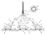
Aは1台の主車両、Bは3台の補助車両で、これらの車両A,B…は搬送用の大型トラックで、車両AはBよりもやや大型のものを使用している。各車両A,Bにおいて1はエンジン、2は排気管系、3は荷台、4は後輪である。これらの車両A,Bは、大型トレーラーであったり砂漠や湿地帯などに適した履帯式を採用した車両であることもある。Hereinafter, an embodiment of the present invention will be described with reference to FIGS. 1 and 2.
A is one main vehicle, B is three auxiliary vehicles, these vehicles A, B... Are large trucks for transportation, and vehicle A uses a slightly larger vehicle than B. In each vehicle A and B, 1 is an engine, 2 is an exhaust pipe system, 3 is a loading platform, and 4 is a rear wheel. These vehicles A and B may be large trailers or vehicles employing a crawler type suitable for deserts and wetlands.
各車両A,Bの荷台3上には、人工降雨(雨雲)発生装置Cの一式が搭載されている。同装置Cとして、荷台3の後部には、荷台3上の平面内のいずれの方向にも移動可能で適宜位置でロックも可能な移動台車6が設けられ、この移動台車6を介して送風機7を内装する吹上装置8が搭載されている。
吹上装置8を移動・ロック可能としたことにより各吹上装置8…の位置関係を仮想円R上により精度よくマッチングさせることができる。しかし、同吹上装置8は、荷台3に固定式にして車両A,Bの移動調整により前記マッチングを図るようにすることもある。
車両Aの吹上装置8は、下部の本体9がドラム型で大きくてその中に送風機7が装備される一方中段は絞りコーン部10とされさらに上部は細い吹上パイプ11になっている。
車両Bの吹上装置8は、下部の本体9がドラム型で大きくてその中に送風機7が装備される一方中段は絞りコーン部10とされさらに上部は細い吹込パイプ12になっている。
特に、車両Aの送風機7は、単一のファンで構成されているが、例えば、図5に示すように、複数個のファンa…で構成してもよい。この場合、各ファンa…の軸芯を垂直でなく傾斜可能にしておいて同じ方向性をもって傾斜設定することで螺旋流を形成させるように構成することができる。この場合、本体9内および/または吹上パイプ11内に螺旋流を確実化するための螺旋羽根をガイドとして設けることがある。A set of artificial rain (rain clouds) generator C is mounted on the
Since the blowing
The blowing
The blowing
In particular, the
荷台3の他の面上には、液タンク(水タンク)13・温蒸気発生装置14・凝結核供給装置15が設置され、液タンク13からは温蒸気発生装置14へ水を供給可能であり、温蒸気発生装置14においては加熱ヒーター(図示省略)により30度程度の温水がつくられ温蒸気を発生できるようになっている。30度とあるのは一例であってそれ以上に加温することもある。温蒸気発生装置14からの温蒸気は図示しない送気手段により吹上装置8内に送り込まれる。この送気手段は、送風機7である吸引手段に置き換えることができる。
凝結核供給装置15からの凝結核は図示しないポンプにより量制御可能に吹上装置8内に送り込まれる。凝結核としては、線香などの発煙手段や塩などが好適である。また、温泉水(例えば、鉄分入り・塩分入り・炭酸入りなど)も好適である。この凝結核供給装置15は、車両A、Bのいずれにも設けられているが、車両Aにのみ設けることもある。A liquid tank (water tank) 13, a
The condensed nuclei from the condensed
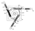
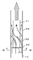
前記車両A上の吹上パイプ11は固定で垂直に伸びているが、車両B上の吹込パイプ12は絞りコーン部10に連通状態を保ちながらフレキシブル管でつながれてシリンダ17により角度変更可能になっている。前記移動台車6には、回転デバイスを備えて吹上パイプ11を旋回自在にしてもよい。吹上パイプ11内には、図2の右上欄のように、螺旋流起生ガイド18…を付して中央のパイプ11自体からも螺旋流を吹き上げるようにしてもよい。
この螺旋流は、図2のように上からみて反時計針回り方向になっているが、場合によってはその逆向きであることもある。その向きは、車両Bの吹込パイプ12…が形成する螺旋向きに一致するものとする。The blowing
The spiral flow is counterclockwise as viewed from above as shown in FIG. 2, but in some cases, the spiral flow may be in the opposite direction. It is assumed that the direction coincides with the spiral direction formed by the blowing
一定の地域範囲に人工的に雨を降らせたい場合、その地域よりも離れた風上となる特定地点を決め、その特定地点に車両A,B…を移動させて集結させる。図1に示すように、車両Aの吹上装置8を仮想円Rの中央に位置させるべく移動制御するとともに、残る車両B…は仮想円R上の120度置きに各吹上装置8…がくるように車両B…をレイアウトする。そして、車両B…の吹込パイプ12…をシリンダ17で高さ制御して図1のように中央の温蒸気の接線方向に吹上げるように制御する。勿論、この位置制御には、車両B…そのものを移動制御すること並びに各移動台車6の相互接近・離反等の移動制御も含まれる。これら全制御を通じてより好ましい螺旋流を起生させるようにする。 When it is desired to artificially rain in a certain area, a specific point that is windward away from the area is determined, and the vehicles A, B. As shown in FIG. 1, movement control is performed so that the blowing
車両Aからの吹上は他の車両Bからの吹上力・量・速度よりも大でその吹上力によって車両Bから吹上げられる温蒸気が引き込まれるようにして螺旋流を形成しそのまま上昇流となる。車両Aからの吹上力を車両Bからの吹上力よりも遅く小さくすることもある。この場合、車両Bからの吹上分が車両Aからの負の力に引き寄せられる傾向となって全体がまとまって螺旋流として上昇する。
図2の右欄のように螺旋流起生ガイド18を設けると、その螺旋流と車両Bからの螺旋流とが協調し合ってさらなる螺旋上昇流を起生することになり、凝結核混じりの温蒸気をより高く上昇させることができるようになる。
また、図2のように、吹上パイプ11の先端あるいは中段もしくは下段などの外周には、パイプ11に隙間をおいてコーン19を装備しその内周に螺旋流促進羽根19aを付けておくことで、車両B…の吹込パイプ12…からの温蒸気の受け入れと螺旋流の形成作用が確実に行われるように構成することができ、この場合、螺旋流は車両Aの吹上パイプ11内からの螺旋流と同調性のある同じ向きに回転させるようにする。
尚、前記車両A,Bに代えて、小型船舶・台船・空母・タンカー等を含む船舶類を図1・図2のように位置制御して集結させ人工雨雲を起生するように構成することもできる。The blow-up from the vehicle A is larger than the blow-up force, amount, and speed from the other vehicle B, and the hot steam blown up from the vehicle B is drawn by the blow-up force to form a spiral flow, and it becomes an upward flow as it is. . The blowing force from the vehicle A may be made slower than the blowing force from the vehicle B. In this case, the amount of blown up from the vehicle B tends to be attracted by the negative force from the vehicle A, and the whole rises as a spiral flow.
If the spiral
Further, as shown in FIG. 2, a
In place of the vehicles A and B, ships including small ships, trolleys, aircraft carriers, tankers, and the like are configured to gather together by controlling the positions as shown in FIGS. 1 and 2 to generate artificial rain clouds. You can also.
図3および図4に示す実施形態は、螺旋流(サイクロン流)を発生させる他の実施形態を示す。
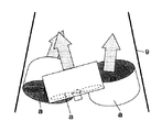
同実施形態は、車両Aの移動台車6上に丸胴型の本体9を装備し、その周位3個所など複数個所を通じて導入パイプ20…を装通するとともに、これら導入パイプ20にそれぞれ車両Bからの吹込パイプ12を接続可能にして螺旋流を起生させるように構成したものである。この接続には、導入パイプ20の端部に備えた脱着具21に吹込パイプ12側に付けたフレキシブルパイプ22を差し込みロックすればよい。本体9の上部には絞りコーン部10を下部に備えたサイクロンパイプ23が連通して立設されており、同パイプ23の中央には温蒸気をストレートあるいは螺旋流として上昇させ得る吹上パイプ11が図示しない支持具を介してサイクロンパイプ23上に伸びるようにして固定されている。この吹上パイプ11からとサイクロンパイプ23内周隙間からの双方からは凝結核混じりの温蒸気が同じ方向に回転しながら螺旋流として上昇してゆく。この場合は、内外二層状に上昇流が起生されるが、図4の右欄のように、通気性のない中央パイプ24の存在により単層状に上昇流が起生されるようにしてもよい。The embodiment shown in FIGS. 3 and 4 shows another embodiment for generating a spiral flow (cyclone flow).
In this embodiment, a round body type
図6に示す実施形態は、凝結核供給装置15をエンジン1に接続の排気管系2として排気ガスそのものを凝結核混じりのガスとして吹上装置8に供給するようにしたものである。液タンク13から温蒸気発生装置14を通じて吹上装置8へ温蒸気を供給する点は上記実施形態と同様であるが、凝結核を排気ガスとした点が異なり、この場合、温蒸気を過給ポンプ25を使用して排気管系2に送り込むことでエンジン1への負荷を軽減している。尚、液タンク13に代えて給水タンクローリーTを組み合わせてもよい。 In the embodiment shown in FIG. 6, the condensed
図7に示す実施形態は、エンジン1の排気熱を利用して温蒸気発生装置14の加熱手段としたもので、それとともに排気ガス分を凝結核を含むガスとして吹上装置8に供給するようにしたものである。26は排気補助ポンプである。
勿論、前記のような凝結核供給装置15を別設してもよい。In the embodiment shown in FIG. 7, the exhaust heat of the
Of course, the condensation
図8は海洋における人工降雨発生方法の実施形態を示す。27は積乱雲で、この例では自然発生したものであるが図示のように空母あるいはタンカーなどの船舶28に人工降雨発生装置Cを搭載したものを適数配して人工的に雨雲を発生させるようにしてもよい。この積乱雲27は上空に至るにしたがってそのもつ潜熱を矢印Sのように放逸してゆき、さらにその放逸に伴って自然に上昇流が発生してその周域にも積乱雲27´…が連続して発生してゆくものである。この例では、凝結核供給装置を備えた人工降雨発生装置Cを搭載した船舶28…を数艘積乱雲27の周域に準備してそこから凝結核混じりの温蒸気を積極的に上昇させて積乱雲27´をつくろうとするものである。この場合、船舶28…は矢印のように周回させて積乱雲27´の発生を積極的かつ確実化するようにしてもよい。 FIG. 8 shows an embodiment of a method for generating artificial rain in the ocean.
図9および図10に示す実施形態のように、吹上パイプ11からの温蒸気がより多く螺旋流として発生するようにしてもよい。吹上パイプ11は太い部分と細い上部とよりなり、その間はドーナツ板状で通孔30…の空いた仕切り板31で取り付けられている。 As in the embodiment shown in FIGS. 9 and 10, more hot steam from the blowing
吹上パイプ11内を上昇してきた温蒸気はその外周において仕切り板31に当り、丁度その個所に通孔30が開いているので温蒸気をより多く通過させるのである。
通孔30を通過した温蒸気は螺旋流起生ガイド32により外パイプ33と吹上パイプ11との間を上昇してゆき、より強い螺旋流で周りを囲まれつつ上昇流となって昇ってゆく。
尚、吹上パイプ11内にも螺旋流起生ガイドを設けてもよい。この場合、同ガイドは、前記ガイド32による螺旋流と同じ方向性をもって同調的かつ増幅的に螺旋流を起生するようにする。通孔30は、螺旋流を起生可能なように周方向にそれぞれ傾斜するパイプにしてもよい。この場合、螺旋流をより確実に得るためガイド32を併設することができるが、省略することもある。The warm steam rising in the blow-up
The warm steam that has passed through the through
In addition, you may provide a spiral flow origin guide also in the blowing
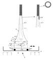
一方、都市などにおいては酷暑期に地表面が熱せられそれに伴う放熱(図11の矢印D)によってヒートアイランド現象が起きている。例えば、同現象に伴い図11に示す高層ビル36(図はその側面図)付近では、海風などの一定の風の流れも手伝ってビル36には放熱分が当りそのまま立面に添って吹き上がる現象が起きている。 On the other hand, in a city or the like, the ground surface is heated during the heat wave, and the heat island phenomenon occurs due to heat radiation (arrow D in FIG. 11). For example, in the vicinity of the high-
図11の実施形態はそうしたヒートアイランド現象を前記人工降雨発生装置Cを使って抑制するようにしたものである。即ち、ビル36で矢印Eのように熱風が立ち上がる裾根部に装置Cを設置した温蒸気を矢印Fのように立ち上げるようにしたものである。前記現象で一帯に流れ込む熱風はビル36前方に設置したブロア37により矢印Xのようにより確実かつ強力にビル36に吹き込むようにする。これにより、人工降雨発生装置Cでつくられた温蒸気はビル36の立面に添って吹き上がる熱風(矢印E)による上昇流に加速されてビル36の上を越えて上空へと上昇させられる。その結果、図示のように人工雲を発生し都市に降雨をもたらし、前記ヒートアイランド現象は抑制されるのである。尚、図示のように、ビル36の屋上に装置Cを設けることもでき、同屋上とビル36の裾根部との併設も可能である。 The embodiment of FIG. 11 is configured to suppress such a heat island phenomenon using the artificial rain generator C. That is, the hot steam in which the apparatus C is installed at the base of the base where hot air rises as indicated by arrow E in the
同じく高伸建造物の1つとして図12に示すタワー40があり、同タワー40の場合は、それを構成する鉄骨メンバーそれ自体から夏季に放熱現象を起こし、この放熱が上昇気流Gを起生する。この上昇気流Gを利用するようにタワー40の基礎上に人工降雨発生装置Cを設置して同調的に上昇させることで降雨を促すようにする。
尚、図示のように、タワー40の上部ステージ40aから牽張材bを介して人工降雨発生装置Cつき気球(熱気球あるいはヘリュームなどガス密封式気球やバルーン)41を揚げてその頂点部分41bあるいは発生装置Cを搭載するゴンドラから凝結核混じりの温蒸気を上昇させるようにしてもよい。41aは揚降用駆動装置である。牽張材bを超軽量で強度のあるチューブとしその中を凝結核混じりの温蒸気を通して吹き上げるようにしてもよい。この気球41は、他にビルとか煙突など高いものの上部を介して揚げるようにしてもよい。この気球41は複数個でもよい。気球41が熱気球の場合は、その上昇用の熱源ガスを温蒸気発生用および凝結核供給用として利用することができるし、温蒸気については周りに漂う蒸気を吸入しそれらを温蒸気に変換して上昇させるようにしてもよい。前記気球41は通常の球形にしてあるが円筒状、あるいは中心に縦穴つきの筒胴型など形は自由である。この場合の縦穴を通じて温蒸気を吹上げるようにしてもよい。Similarly, there is a
As shown in the drawing, a
また図13の実施形態は、同じく高伸建造物の1つである煙突42の発生ガスの上昇力を利用して温蒸気を上昇させるように構成されており、煙突42の基面には人工降雨発生装置Cを設置するとともにその吹上パイプ43を煙突42に添わせて煙突42の先端口部まで導いて構成したものである。 Further, the embodiment of FIG. 13 is configured to raise the warm steam by using the rising force of the gas generated by the
図14は高速等の路線に設けられたトンネル45内に溜まる傾向となる内部排気ガスをその車両進行方向に送気手段46により送り出すとともに、それらのガスを溜まりフード47内に掻き集めたあと、その上面に設けたブロア48で上昇気流Iとするもので、その上昇気流Iの軌道上に吹上パイプ49がくるように人工降雨発生装置Cをトンネル45外に設置してなるものである。その結果、温蒸気はトンネル45内からのガス分とともに上昇して付近あるいは流れた先で降雨をもたらすのである。 FIG. 14 shows that exhaust gas that tends to accumulate in a
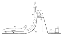
図15の実施形態は、ジェット戦闘機などの航空機51から出されるジェット燃焼ガスJの流れを誘導ガイド52を通じて上昇流Kとなし、その軌道上に相当するガイド52上に吹上パイプ53がくるようにして人工降雨発生装置Cを設置したものであり、これにより、付近一帯あるいは離れた地帯に降雨をもたらすことができるものである。 In the embodiment of FIG. 15, the flow of the jet combustion gas J emitted from the
A,B 車両
C 人工降雨発生装置
8 吹上装置
11 吹上パイプ
12 吹込パイプ
13 液タンク
14 温蒸気発生装置
15 凝結核供給装置A, B Vehicle C
Claims (1)
Priority Applications (1)
| Application Number | Priority Date | Filing Date | Title |
|---|---|---|---|
| JP2010265720A JP5719984B2 (en) | 2010-11-10 | 2010-11-10 | Artificial rainfall generator |
Applications Claiming Priority (1)
| Application Number | Priority Date | Filing Date | Title |
|---|---|---|---|
| JP2010265720A JP5719984B2 (en) | 2010-11-10 | 2010-11-10 | Artificial rainfall generator |
Publications (2)
| Publication Number | Publication Date |
|---|---|
| JP2012100640A true JP2012100640A (en) | 2012-05-31 |
| JP5719984B2 JP5719984B2 (en) | 2015-05-20 |
Family
ID=46391873
Family Applications (1)
| Application Number | Title | Priority Date | Filing Date |
|---|---|---|---|
| JP2010265720A Active JP5719984B2 (en) | 2010-11-10 | 2010-11-10 | Artificial rainfall generator |
Country Status (1)
| Country | Link |
|---|---|
| JP (1) | JP5719984B2 (en) |
Cited By (5)
| Publication number | Priority date | Publication date | Assignee | Title |
|---|---|---|---|---|
| CN103718907A (en) * | 2013-09-10 | 2014-04-16 | 高传友 | Economically feasible artificial rainfall agent and rainfall achieving method |
| RU2578537C1 (en) * | 2015-03-02 | 2016-03-27 | Федеральное Государственное Бюджетное Учреждение "Главная геофизическая обсерватория им. А.И. Воейкова "ФГБУ ГГО" | Method of combating drought with artificial inducing of rainfall |
| JP6099111B1 (en) * | 2016-07-19 | 2017-03-22 | 英世 村上 | Water vapor release device, water vapor release system, and water vapor release method |
| WO2018009051A1 (en) * | 2016-07-05 | 2018-01-11 | Kau Kong Hoi | An apparatus for enriching humidity in atmosphere and a method therefor |
| CN108828158A (en) * | 2018-07-31 | 2018-11-16 | 北京市水科学技术研究院 | The measuring device of Carbon flux under a kind of artificial rainfall condition |
Citations (5)
| Publication number | Priority date | Publication date | Assignee | Title |
|---|---|---|---|---|
| US5492274A (en) * | 1990-07-05 | 1996-02-20 | Geophysical Engineering Company | Method of and means for weather modification |
| JP3084832U (en) * | 2001-09-21 | 2002-03-29 | 裕 林 | Artificial rainfall device |
| WO2008050799A1 (en) * | 2006-10-26 | 2008-05-02 | Tomoaki Nakamura | Method of changing weather and water vapor generator for changing weather |
| JP2010007047A (en) * | 2008-05-29 | 2010-01-14 | Mitsuhiro Fujiwara | Method of generating artificial rainmaking or the like |
| JP2010155957A (en) * | 2009-01-04 | 2010-07-15 | Shinji Kobayashi | Global warming prevention-water supply system |
-
2010
- 2010-11-10 JP JP2010265720A patent/JP5719984B2/en active Active
Patent Citations (5)
| Publication number | Priority date | Publication date | Assignee | Title |
|---|---|---|---|---|
| US5492274A (en) * | 1990-07-05 | 1996-02-20 | Geophysical Engineering Company | Method of and means for weather modification |
| JP3084832U (en) * | 2001-09-21 | 2002-03-29 | 裕 林 | Artificial rainfall device |
| WO2008050799A1 (en) * | 2006-10-26 | 2008-05-02 | Tomoaki Nakamura | Method of changing weather and water vapor generator for changing weather |
| JP2010007047A (en) * | 2008-05-29 | 2010-01-14 | Mitsuhiro Fujiwara | Method of generating artificial rainmaking or the like |
| JP2010155957A (en) * | 2009-01-04 | 2010-07-15 | Shinji Kobayashi | Global warming prevention-water supply system |
Cited By (6)
| Publication number | Priority date | Publication date | Assignee | Title |
|---|---|---|---|---|
| CN103718907A (en) * | 2013-09-10 | 2014-04-16 | 高传友 | Economically feasible artificial rainfall agent and rainfall achieving method |
| RU2578537C1 (en) * | 2015-03-02 | 2016-03-27 | Федеральное Государственное Бюджетное Учреждение "Главная геофизическая обсерватория им. А.И. Воейкова "ФГБУ ГГО" | Method of combating drought with artificial inducing of rainfall |
| WO2018009051A1 (en) * | 2016-07-05 | 2018-01-11 | Kau Kong Hoi | An apparatus for enriching humidity in atmosphere and a method therefor |
| JP6099111B1 (en) * | 2016-07-19 | 2017-03-22 | 英世 村上 | Water vapor release device, water vapor release system, and water vapor release method |
| CN108828158A (en) * | 2018-07-31 | 2018-11-16 | 北京市水科学技术研究院 | The measuring device of Carbon flux under a kind of artificial rainfall condition |
| CN108828158B (en) * | 2018-07-31 | 2024-01-30 | 北京市水科学技术研究院 | Measurement device for carbon flux under artificial rainfall condition |
Also Published As
| Publication number | Publication date |
|---|---|
| JP5719984B2 (en) | 2015-05-20 |
Similar Documents
| Publication | Publication Date | Title |
|---|---|---|
| JP5719984B2 (en) | Artificial rainfall generator | |
| CN102530231B (en) | High-altitude vehicle | |
| JP5685697B2 (en) | Artificial rain generation method | |
| CN1168630C (en) | Balloon trajectory control system | |
| CN205332926U (en) | Railway carriage or compartment style laser low latitude security protection system | |
| CN104280204B (en) | Wind tunnel | |
| US8853880B2 (en) | Eddy carrier type wind power collection device | |
| US20100140390A1 (en) | Flying Wind Energy Conversion Apparatus | |
| CN107991055A (en) | Gobi Integrated environment wind tunnel simulation device | |
| US8643209B2 (en) | Air-floating carrier type wind power collection device | |
| CN106438209A (en) | Methods for utilizing wind energy inside and outside vehicle as well as windshield air curtain device | |
| JP2023075121A5 (en) | ||
| JP2007522997A (en) | Auxiliary drive by changing the direction of fluid flow | |
| CN205293056U (en) | Dynamic quick -witted flames of anger hot air balloon | |
| CN104652345A (en) | Haze dispersing and surface air cooling system | |
| JP2006342790A (en) | Method for generating power using jet stream | |
| RU2201379C2 (en) | Aerostatic apparatus | |
| JP2019520517A5 (en) | ||
| WO2014061759A2 (en) | System for space propulsion and staying in space (staying in above-stratosphere air) | |
| US8692406B2 (en) | Air-guiding carrier type wind power collection device | |
| RU2284279C1 (en) | Aerostat | |
| CN206467630U (en) | A kind of defogging vehicle | |
| CN102705167A (en) | Lotus-shaped wind power generation device | |
| CN207120866U (en) | A kind of gas-floating facility | |
| CN104390294B (en) | Aeration cooling system and method under closed operation environment |
Legal Events
| Date | Code | Title | Description |
|---|---|---|---|
| A621 | Written request for application examination |
Free format text: JAPANESE INTERMEDIATE CODE: A621 Effective date: 20131031 |
|
| A521 | Written amendment |
Free format text: JAPANESE INTERMEDIATE CODE: A523 Effective date: 20140114 |
|
| A977 | Report on retrieval |
Free format text: JAPANESE INTERMEDIATE CODE: A971007 Effective date: 20140529 |
|
| A131 | Notification of reasons for refusal |
Free format text: JAPANESE INTERMEDIATE CODE: A131 Effective date: 20140610 |
|
| A521 | Written amendment |
Free format text: JAPANESE INTERMEDIATE CODE: A523 Effective date: 20140730 |
|
| A711 | Notification of change in applicant |
Free format text: JAPANESE INTERMEDIATE CODE: A711 Effective date: 20140730 |
|
| A01 | Written decision to grant a patent or to grant a registration (utility model) |
Free format text: JAPANESE INTERMEDIATE CODE: A01 Effective date: 20141216 |
|
| A61 | First payment of annual fees (during grant procedure) |
Free format text: JAPANESE INTERMEDIATE CODE: A61 Effective date: 20141227 |
|
| R150 | Certificate of patent or registration of utility model |
Ref document number: 5719984 Country of ref document: JP Free format text: JAPANESE INTERMEDIATE CODE: R150 |
|
| R250 | Receipt of annual fees |
Free format text: JAPANESE INTERMEDIATE CODE: R250 |
|
| R250 | Receipt of annual fees |
Free format text: JAPANESE INTERMEDIATE CODE: R250 |