JP2012097807A - Ball screw nut removing and returning jig, and nut removing and returning method using jig - Google Patents
Ball screw nut removing and returning jig, and nut removing and returning method using jig Download PDFInfo
- Publication number
- JP2012097807A JP2012097807A JP2010245571A JP2010245571A JP2012097807A JP 2012097807 A JP2012097807 A JP 2012097807A JP 2010245571 A JP2010245571 A JP 2010245571A JP 2010245571 A JP2010245571 A JP 2010245571A JP 2012097807 A JP2012097807 A JP 2012097807A
- Authority
- JP
- Japan
- Prior art keywords
- nut
- screw shaft
- screw
- shaft
- spiral groove
- Prior art date
- Legal status (The legal status is an assumption and is not a legal conclusion. Google has not performed a legal analysis and makes no representation as to the accuracy of the status listed.)
- Granted
Links
Images


Landscapes
- Transmission Devices (AREA)
Abstract
Description
この発明は、ボールねじのナットをねじ軸から仮軸に移す工程と、仮軸からねじ軸に戻す工程を有するナット着脱方法で使用する治具に関する。 The present invention relates to a jig used in a nut attaching / detaching method including a step of transferring a nut of a ball screw from a screw shaft to a temporary shaft and a step of returning the nut from the temporary shaft to the screw shaft.
ボールねじは、内周面に螺旋溝が形成されたナットと、外周面に螺旋溝が形成されたねじ軸と、ナットの螺旋溝とねじ軸の螺旋溝で形成される軌道(転動路)の間に配置されたボールと、ボールを軌道の終点から始点に戻すボール戻し経路とを備え、前記軌道内をボールが転動することで前記ナットがねじ軸に対して相対移動する装置である。
ボールねじのナットの軸方向両端部には、ねじ軸との隙間を塞ぐシールが取り付けられている。また、ボール戻し経路として循環チューブを用いる場合は、ナットに設けた穴に循環チューブの脚部が差し込まれ、脚部の先端に形成されたタング部がねじ軸の螺旋溝内に配置されている。
The ball screw has a nut formed with a spiral groove on the inner peripheral surface, a screw shaft formed with a spiral groove on the outer peripheral surface, and a raceway (rolling path) formed by the spiral groove of the nut and the spiral groove of the screw shaft. And a ball return path that returns the ball from the end point of the track to the start point, and the nut moves relative to the screw shaft by rolling the ball in the track. .
Seals are attached to both ends of the ball screw nut in the axial direction to close the gap with the screw shaft. Further, when the circulation tube is used as the ball return path, the leg of the circulation tube is inserted into the hole provided in the nut, and the tongue formed at the tip of the leg is disposed in the spiral groove of the screw shaft. .
従来より、グリース供給などのメンテナンスのために、ボールねじのナットを、内部に配置されたボールの組み込み状態を保持してねじ軸から仮軸に移すことが行われている。具体的には、ねじ軸の端部に仮軸を接続して、ねじ軸をナットに対して相対的に回転することで、ナットおよびボールをねじ軸から仮軸に移している。そして、メンテナンスを終えた後に、ねじ軸を反対向きに回転することで、ナットとボールを仮軸からねじ軸に戻している。 Conventionally, for maintenance such as grease supply, a nut of a ball screw is transferred from a screw shaft to a temporary shaft while maintaining the assembled state of the ball disposed inside. Specifically, the nut and the ball are moved from the screw shaft to the temporary shaft by connecting the temporary shaft to the end of the screw shaft and rotating the screw shaft relative to the nut. After the maintenance is completed, the nut and the ball are returned from the temporary shaft to the screw shaft by rotating the screw shaft in the opposite direction.
このようなボールねじのナット着脱方法の従来例としては、例えば、下記の特許文献1に記載された方法がある。特許文献1の方法では、ねじ軸と仮軸とを正確に芯合わせするために、仮軸として、ねじ軸の螺旋溝の谷径にほぼ等しい軸部と、この軸部の一端に形成された、ねじ軸の軸方向端部に設けたセンタ穴と嵌合する芯合わせ用突体と、を有するものを使用している。 As a conventional example of such a ball screw nut attaching / detaching method, for example, there is a method described in Patent Document 1 below. In the method of Patent Document 1, in order to accurately align the screw shaft and the temporary shaft, the temporary shaft is formed at a shaft portion substantially equal to the valley diameter of the spiral groove of the screw shaft and at one end of the shaft portion. And a centering protrusion that fits into a center hole provided at an axial end of the screw shaft.
上述のボールねじのナット着脱方法においては、ナットを仮軸からねじ軸に戻す際に、ねじ軸の螺旋溝とナットの螺旋溝がずれていると、接触シールのリップ部や循環チューブのタング部がねじ軸と干渉して損傷が生じる恐れがある。特許文献1には、この螺旋溝のずれを防止することに関する記載がない。
この発明の課題は、ボールねじのナットをねじ軸から仮軸に移す工程と、仮軸からねじ軸に戻す工程を有するナット着脱方法で、ナットを仮軸からねじ軸に戻す際に、ねじ軸の螺旋溝とナットの螺旋溝との間にずれが生じないようにすることである。
In the above-described ball screw nut attaching / detaching method, when the nut is returned from the temporary shaft to the screw shaft, if the spiral groove of the screw shaft and the spiral groove of the nut are misaligned, the lip portion of the contact seal or the tongue portion of the circulation tube May interfere with the screw shaft and cause damage. Japanese Patent Application Laid-Open No. H10-228707 does not describe prevention of the shift of the spiral groove.
An object of the present invention is to provide a nut attaching method including a step of moving a nut of a ball screw from a screw shaft to a temporary shaft and a step of returning from the temporary shaft to the screw shaft. This is to prevent a shift between the spiral groove of the nut and the spiral groove of the nut.
上記課題を解決するために、この発明は、ボールねじのねじ軸の一端に仮軸を固定して、ねじ軸をナットに対して相対的に回転することで、ナットを、内部に配置されたボールの組み込み状態を保持してねじ軸から仮軸に移すナット外し工程と、ねじ軸をナットに対して相対的にナット外し工程とは反対側に回転することで、ナットを、内部に配置されたボールの組み込み状態を保持して仮軸からねじ軸に戻すナット戻し工程と、を有するボールねじのナット着脱方法で使用する治具であって、ねじ軸の螺旋溝内に配置され、ねじ軸のナットに対する相対回転時にねじ軸の螺旋溝を案内する案内部と、ナットに対する固定部と、を有することを特徴とするボールねじのナット着脱用治具を提供する。 In order to solve the above-mentioned problems, the present invention fixes a temporary shaft to one end of a screw shaft of a ball screw, and rotates the screw shaft relative to the nut to arrange the nut inside. The nut is placed inside by removing the nut and moving the screw shaft from the screw shaft to the temporary shaft while rotating the ball shaft relative to the nut. And a nut return step for holding the assembled state of the ball and returning it from the temporary shaft to the screw shaft, and a jig for use in a nut mounting method of the ball screw, which is disposed in the spiral groove of the screw shaft, A ball screw nut attaching / detaching jig is provided that includes a guide portion that guides a spiral groove of a screw shaft during relative rotation with respect to the nut, and a fixing portion with respect to the nut.
この発明の治具を用いたボールねじのナット着脱方法として、前記案内部をねじ軸の螺旋溝内に配置した状態で、前記固定部により、この治具をナットに固定することで、ナットを外す前のねじ軸の螺旋溝とナットの螺旋溝との関係を設定した後、前記案内部でねじ軸の螺旋溝を案内しながら前記ナット外し工程を行い、前記治具を外さないで、前記案内部でねじ軸の螺旋溝を案内しながら前記ナット戻し工程を行う方法が挙げられる。 As a ball screw nut attaching / detaching method using the jig of the present invention, the jig is fixed to the nut by the fixing portion in a state where the guide portion is disposed in the spiral groove of the screw shaft. After setting the relationship between the helical groove of the screw shaft and the helical groove of the nut before removing, the nut removing step while guiding the helical groove of the screw shaft with the guide portion, without removing the jig, There is a method of performing the nut returning step while guiding the spiral groove of the screw shaft with the guide portion.
この方法によれば、ナット外し工程とナット戻し工程で、ねじ軸は、螺旋溝が前記治具の案内部で案内されながら、ナットに対して軸方向に相対移動するため、ナット戻し工程の後に、ナットを外す前のねじ軸の螺旋溝とナットの螺旋溝との関係が保持された状態となる。したがって、この発明のナット着脱用治具によれば、前記ナット着脱方法でナットを仮軸からねじ軸に戻す際に、ねじ軸の螺旋溝とナットの螺旋溝との間にずれが生じないようにすることができる。
この発明のナット着脱用治具の例として、前記固定部は、ナットの外周部を保持するクランプからなり、前記案内部をねじ軸の径方向に進退させる進退部材と、進退部材とクランプをねじ軸の軸方向に沿って結合する結合部材と、を有するものが挙げられる。この治具によれば、ボールねじに対する治具の付け外しを簡単に行うことができる。
According to this method, in the nut removing step and the nut returning step, the screw shaft moves relative to the nut in the axial direction while the spiral groove is guided by the guide portion of the jig. The relationship between the spiral groove of the screw shaft before the nut is removed and the spiral groove of the nut is maintained. Therefore, according to the nut attaching / detaching jig of the present invention, when the nut is returned from the temporary shaft to the screw shaft by the nut attaching / detaching method, no deviation occurs between the spiral groove of the screw shaft and the spiral groove of the nut. Can be.
As an example of the nut attaching / detaching jig according to the present invention, the fixing portion includes a clamp that holds an outer peripheral portion of the nut. And a coupling member coupled along the axial direction of the shaft. According to this jig, the jig can be easily attached to and detached from the ball screw.
この発明の治具を用いて、ボールねじのナットをねじ軸から仮軸に移すナット外し工程と、ナットを仮軸からねじ軸に戻すナット戻し工程と、を有するナット着脱方法を行うことにより、ナット戻し工程でねじ軸の螺旋溝とナットの螺旋溝との間にずれが生じないようにすることができる。 By using the jig of the present invention, by performing a nut removing method that includes a nut removing step of moving the nut of the ball screw from the screw shaft to the temporary shaft, and a nut returning step of returning the nut from the temporary shaft to the screw shaft, It is possible to prevent a shift between the spiral groove of the screw shaft and the spiral groove of the nut in the nut returning process.
以下、この発明の実施形態について説明する。
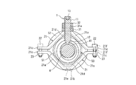
この実施形態のボールねじのナット着脱用治具は、図1および2に示すように、ガイド部材1およびクランプ2と、これらを結合するための板状部材31、ナット32、およびボルト33とで構成されている。
ガイド部材1は、所定長さの丸棒材に雄ねじが形成された雄ねじ部11と、その先端に雄ねじ部11の谷径より小径の軸状に形成された突起12と、からなり、雄ねじ部11の基端部に六角穴13が形成されている。突起12の先端は球面に形成されている。この突起12は、ボールねじのねじ軸4の螺旋溝41に僅かな隙間で嵌まる寸法を有する。
Embodiments of the present invention will be described below.
As shown in FIGS. 1 and 2, the ball screw nut attaching / detaching jig of this embodiment includes a guide member 1 and a
The guide member 1 includes a
クランプ2は、ボールねじのナット5の外周部を、ナット5の断面円を二分割した両側から保持する一対の保持部材21と、両保持部材21を結合するボルト22およびナット23と、からなる。保持部材21は、ナット5の外周面と接触させる一対の傾斜部21aと、両傾斜部21aを水平に連結する水平連結部21bと、各傾斜部21aの外側に水平に延びる水平端部21cと、が一体に形成されたものである。
The
保持部材21の傾斜部21aおよび水平連結部21bには、ナット5の軸方向に沿った一端に、ナット5の軸方向一端面に接触させる縁部21dが形成されている。保持部材21の水平連結部21bの中心に、ナット5の径方向に貫通する雌ねじ孔21eが形成されている。保持部材21の水平端部21cには、ボルト22の軸部が入る貫通孔21fが形成されている。
The
板状部材31には、ガイド部材1の雄ねじ部11に対応する雌ねじ孔31aと、クランプ2の保持部材21に形成された雌ねじ孔21eに対応する貫通孔31bが形成されている。板状部材31の一端が、一方の保持部材21の水平連結部21bの外側に、ボルト33で固定されている。すなわち、ボルト33の軸部が、板状部材31の貫通孔31bを通り、その先端が雌ねじ孔21eに螺合されている。
板状部材31の他端の雌ねじ孔31aに、ガイド部材1の雄ねじ部11が螺合され、その基端部側にナット32が螺合されている。これにより、板状部材31の他端にガイド部材1が、ねじ軸4の径方向での位置が調整可能に取り付けられている。
The plate-
The
なお、ねじ軸4の軸方向端部42は、螺旋溝41の谷径より小径の円筒状に形成されている。また、ナット5の軸方向両端の内部に接触シール53が取り付けられているが、図1ではフランジ52内の接触シール53のみを破線で示し、円筒部51のフランジ52とは反対側の端部に破線で示すことを省略している。また、このボールねじはボール戻し経路として循環チューブ54を有する。
The
次に、この実施形態のナット着脱用治具を用いたボールねじのナット着脱方法を説明する。
先ず、図3(a)に示すように、長尺な円筒体であって、ねじ軸4の螺旋溝の谷径より僅かに小さい外径の仮軸6の一端に、ねじ軸4の軸方向端部42を挿入する。なお、仮軸6の他端には、ナット脱落防止用の円板状ストッパー7が取り付けられている。この円板状ストッパー7の外径は、ナット5に取り付けられたシール53の外径よりも大きい。
Next, a nut screw attaching / detaching method using the nut attaching / detaching jig of this embodiment will be described.
First, as shown in FIG. 3A, an axial direction of the screw shaft 4 is formed on one end of a temporary shaft 6 which is a long cylindrical body and has an outer diameter slightly smaller than the valley diameter of the spiral groove of the screw shaft 4. Insert the
次に、ナット5の円筒部51のフランジ52とは反対側の端部の外周部をクランプ2で保持する。その際に、ガイド部材1の突起12が、ねじ軸4の螺旋溝41の上方に配置されるようにする。次に、六角穴13に六角レンチを嵌めて雄ねじ部11を回転させることにより、ガイド部材1の突起12をねじ軸4の螺旋溝41に挿入する。これにより、ねじ軸4の螺旋溝41とナット5の螺旋溝との関係を設定する。
Next, the outer peripheral portion of the end portion of the
次に、ナット外し工程を行う。すなわち、ナット5を固定した状態でねじ軸4を回転する。これにより、ねじ軸4は、螺旋溝41がガイド部材1の突起12で案内されながら、ナット5に対して軸方向に相対移動し、ナット5は、内部に配置されたボールとともにねじ軸4から外れて仮軸6に移る。図3(b)はこの状態を示す。
次に、図3(b)の状態でメンテナンス作業を行った後、ナット戻し工程を行う。すなわち、ナット5を固定した状態でねじ軸4をナット外し工程とは反対側に回転する。これにより、ねじ軸4は、螺旋溝41がガイド部材1の突起12で案内されながら、ナット5に対して軸方向に相対移動し、ナット5は、内部に配置されたボールとともにねじ軸4に戻り、図3(a)に示す状態となる。
Next, a nut removing process is performed. That is, the screw shaft 4 is rotated with the
Next, after performing the maintenance work in the state of FIG. 3B, a nut returning step is performed. That is, with the
このように、ナット外し工程とナット戻し工程で、ねじ軸4は、螺旋溝41がガイド部材1の突起12で案内されながら、ナット5に対して軸方向に相対移動するため、ナット戻し工程の後に、ナット5を外す前のねじ軸4の螺旋溝41とナット5の螺旋溝との関係が保持されている。
これにより、前記ナット着脱方法でナットを仮軸からねじ軸に戻す際に、ねじ軸の螺旋溝とナットの螺旋溝との間にずれが生じないようにすることができる。
Thus, in the nut removing process and the nut returning process, the screw shaft 4 moves relative to the
Accordingly, when the nut is returned from the temporary shaft to the screw shaft by the nut attaching / detaching method, it is possible to prevent a deviation from occurring between the spiral groove of the screw shaft and the spiral groove of the nut.
なお、この方法では、クランプ2により、ナット5の円筒部51のフランジ52とは反対側の端部で、ナット5の外周部を保持しているが、フランジ52の直径に対応させた長いボルト22を用いれば、このクランプ2を用いてフランジ52の外周部を保持することもできる。その場合は、ガイド部材1を、図1でクランプ2より左側に配置する。
すなわち、この実施形態のナット着脱用治具を構成するクランプ2は、ボルト22の長さを変えることで複数の直径のナット5に使用できる。また、板状部材31の貫通穴31bを軸方向に延びる長穴にすることで、クランプ2でナット5を保持した後に、ガイド部材1の軸方向への取り付け位置を調整することができる。
In this method, the
That is, the
この実施形態のナット着脱用治具において、ガイド部材1の突起12が、この発明のナット着脱用治具の案内部に相当する。また、ガイド部材1の雄ねじ部11とナット32と板状部材31の雌ねじ孔31aが、この発明のナット着脱用治具の進退部材に相当する。また、板状部材31、ナット32、およびボルト33が、この発明のナット着脱用治具の結合部材に相当する。
In the nut attaching / detaching jig of this embodiment, the
なお、図1および2のガイド部材1の突起12は、先端を球面にしてあるが、ねじ軸の螺旋溝内に挿入されて、ねじ軸のナットに対する相対回転時にねじ軸の螺旋溝を案内可能であれば、円柱状や四角柱状などの形状になっていてもよい。また、突起12の材質としては、鋼、プラスチック、硬質ゴムが挙げられるが、ねじ軸4の螺旋溝41に傷が付かないように、プラスチックまたは硬質ゴムを用いることが望ましい。
また、雄ねじ部11の先端に、突起12に代えて、図4および5に示すように、ねじ軸4の螺旋溝41に僅かな隙間で嵌まる円弧面14aを有する嵌合部14が形成されたガイド部材10を用いてもよい。
The
In addition, instead of the
さらに、図6に示すように、中心穴81と取付穴82を有する円板状部材8も、この発明のナット着脱用治具の実施形態である。円板状部材8の中心穴81が案内部に、取付穴82が固定部に相当する。
図7に示すように、円板状部材8は、中心穴81にねじ軸4を通した状態で、取付穴82でナット5の軸方向一端に設けた凹部55の底面にボルト9で固定される。中心穴81は、ねじ軸4の断面形状に応じて、前述のナット外し工程およびナット戻し工程で螺旋溝41を案内可能な形状を有する。
Furthermore, as shown in FIG. 6, the disk-shaped
As shown in FIG. 7, the disk-shaped
1 ガイド部材
10 ガイド部材
11 雄ねじ部(進退部材)
12 突起(案内部)
13 六角穴
14 嵌合部(案内部)
14a 円弧面
2 クランプ(固定部)
21 保持部材
21a 傾斜部
21b 水平連結部
21c 水平端部
21d 縁部
21e 雌ねじ孔
21f 貫通孔
22 ボルト
23 ナット
31 板状部材(結合部材)
31a 雌ねじ孔
31b 貫通孔
32 ナット(結合部材)
33 ボルト(結合部材)
4 ボールねじのねじ軸
41 ねじ軸の螺旋溝
42 ねじ軸の軸方向端部
5 ボールねじのナット
53 接触シール
54 循環チューブ
55 凹部
6 仮軸
7 円板状ストッパー
81 中心穴(案内部)
82 取付穴(固定部)
8 円板状部材
9 ボルト
DESCRIPTION OF SYMBOLS 1
12 Protrusion (guide part)
13
21
31a
33 Bolt (joining member)
4 Ball
82 Mounting hole (fixed part)
8 Disc-shaped member 9 Bolt
Claims (3)
ねじ軸をナットに対して相対的にナット外し工程とは反対側に回転することで、ナットを、内部に配置されたボールの組み込み状態を保持して仮軸からねじ軸に戻すナット戻し工程と、
を有するボールねじのナット着脱方法で使用する治具であって、
ねじ軸の螺旋溝内に配置され、ねじ軸のナットに対する相対回転時にねじ軸の螺旋溝を案内する案内部と、ナットに対する固定部と、を有することを特徴とするボールねじのナット着脱用治具。 A temporary shaft is fixed to one end of the screw shaft of the ball screw, and the screw shaft is rotated relative to the nut so that the nut is temporarily mounted from the screw shaft while maintaining the assembled state of the ball disposed inside. Removing the nut to the shaft,
A nut return step of rotating the screw shaft relative to the nut to the opposite side of the nut removing step to return the nut to the screw shaft from the temporary shaft while maintaining the assembled state of the ball disposed inside; ,
A jig used in a nut screw attaching / detaching method having
A ball screw nut attaching and detaching feature characterized by having a guide portion that is disposed in the spiral groove of the screw shaft and guides the spiral groove of the screw shaft when the screw shaft rotates relative to the nut, and a fixing portion for the nut. Ingredients.
前記案内部をねじ軸の径方向に進退させる進退部材と、進退部材とクランプをねじ軸の軸方向に沿って結合する結合部材と、を有する請求項1記載のボールねじのナット着脱用治具。 The fixed portion is composed of a clamp that holds the outer peripheral portion of the nut,
The ball screw nut attaching / detaching jig according to claim 1, further comprising: an advance / retreat member that advances and retracts the guide portion in the radial direction of the screw shaft; and a coupling member that couples the advance / retreat member and the clamp along the axial direction of the screw shaft. .
ねじ軸をナットに対して相対的にナット外し工程とは反対側に回転することで、ナットを、内部に配置されたボールの組み込み状態を保持して仮軸からねじ軸に戻すナット戻し工程と、
を有するボールねじのナット着脱方法であって、
請求項1または2記載の治具を用い、
前記案内部をねじ軸の螺旋溝内に配置した状態で、前記固定部により前記治具をナットに固定することで、ナットを外す前のねじ軸の螺旋溝とナットの螺旋溝との関係を設定した後、
前記案内部でねじ軸の螺旋溝を案内しながら前記ナット外し工程を行い、
前記治具を外さないで、前記案内部でねじ軸の螺旋溝を案内しながら前記ナット戻し工程を行うことを特徴とするボールねじのナット着脱方法。 A temporary shaft is fixed to one end of the screw shaft of the ball screw, and the screw shaft is rotated relative to the nut so that the nut is temporarily mounted from the screw shaft while maintaining the assembled state of the ball disposed inside. Removing the nut to the shaft,
A nut return step of rotating the screw shaft relative to the nut to the opposite side of the nut removing step to return the nut to the screw shaft from the temporary shaft while maintaining the assembled state of the ball disposed inside; ,
A ball screw nut attaching / detaching method comprising:
Using the jig according to claim 1 or 2,
In the state where the guide portion is disposed in the spiral groove of the screw shaft, the jig is fixed to the nut by the fixing portion, whereby the relationship between the spiral groove of the screw shaft and the spiral groove of the nut before the nut is removed. After setting
The nut removing step is performed while guiding the spiral groove of the screw shaft with the guide portion,
A nut screw attaching / detaching method characterized by performing the nut returning step while guiding the spiral groove of the screw shaft with the guide portion without removing the jig.
Priority Applications (1)
| Application Number | Priority Date | Filing Date | Title |
|---|---|---|---|
| JP2010245571A JP5531914B2 (en) | 2010-11-01 | 2010-11-01 | Ball screw nut attaching / detaching jig and nut attaching / detaching method using the same |
Applications Claiming Priority (1)
| Application Number | Priority Date | Filing Date | Title |
|---|---|---|---|
| JP2010245571A JP5531914B2 (en) | 2010-11-01 | 2010-11-01 | Ball screw nut attaching / detaching jig and nut attaching / detaching method using the same |
Publications (2)
| Publication Number | Publication Date |
|---|---|
| JP2012097807A true JP2012097807A (en) | 2012-05-24 |
| JP5531914B2 JP5531914B2 (en) | 2014-06-25 |
Family
ID=46389954
Family Applications (1)
| Application Number | Title | Priority Date | Filing Date |
|---|---|---|---|
| JP2010245571A Expired - Fee Related JP5531914B2 (en) | 2010-11-01 | 2010-11-01 | Ball screw nut attaching / detaching jig and nut attaching / detaching method using the same |
Country Status (1)
| Country | Link |
|---|---|
| JP (1) | JP5531914B2 (en) |
Cited By (2)
| Publication number | Priority date | Publication date | Assignee | Title |
|---|---|---|---|---|
| CN109709030A (en) * | 2019-02-15 | 2019-05-03 | 南通市产品质量监督检验所 | A kind of high strength exploitation rubbing surface anti-slip coefficient detection integration test machine |
| KR102321069B1 (en) * | 2021-05-14 | 2021-11-03 | (주)홍디자인 | Play table clamp device |
-
2010
- 2010-11-01 JP JP2010245571A patent/JP5531914B2/en not_active Expired - Fee Related
Cited By (2)
| Publication number | Priority date | Publication date | Assignee | Title |
|---|---|---|---|---|
| CN109709030A (en) * | 2019-02-15 | 2019-05-03 | 南通市产品质量监督检验所 | A kind of high strength exploitation rubbing surface anti-slip coefficient detection integration test machine |
| KR102321069B1 (en) * | 2021-05-14 | 2021-11-03 | (주)홍디자인 | Play table clamp device |
Also Published As
| Publication number | Publication date |
|---|---|
| JP5531914B2 (en) | 2014-06-25 |
Similar Documents
| Publication | Publication Date | Title |
|---|---|---|
| JP5465981B2 (en) | Sleeve removal device from seaming spindle | |
| US10113621B2 (en) | Method for manufacturing ball screw and ball screw | |
| CN203471083U (en) | Inner centering tensioning clamp | |
| JP5363271B2 (en) | Sleeve removal device from seaming spindle | |
| JP2012026536A (en) | Fitting member positioning device | |
| JP5531914B2 (en) | Ball screw nut attaching / detaching jig and nut attaching / detaching method using the same | |
| JP5301744B1 (en) | Chuck mechanism for machine tools, claw material and lathe | |
| US8590431B2 (en) | Protective gear socket assemblies and methods of fabricating the same | |
| US9127719B2 (en) | Method of manufacturing a bearing assembly | |
| US20170297183A1 (en) | Screwdriver bit assembly with a magnetic structure | |
| TWI634971B (en) | Wrench adapter | |
| JP2020153462A (en) | Bearing attachment structure | |
| JP6213325B2 (en) | Male screw | |
| JP5374451B2 (en) | Injection machine for injection molding machine | |
| JP2008254142A (en) | Screw fastening tool | |
| US11168791B1 (en) | Brush seal mounting for a vise jaw | |
| WO2016138867A1 (en) | Coupling bearing filled with rolling elements, and manufacturing method thereof | |
| JPH09287607A (en) | Bolt, and track rail for linear movement guide device with bolt incorporated | |
| CN215355448U (en) | Pipe fitting plastic tool | |
| JP5455075B2 (en) | Centering tool for press ring | |
| JP5394427B2 (en) | Removal method of grinding wheel base metal, removal jig, grinding machine and grinding wheel base metal | |
| JP2009008235A (en) | Pin type retainer and method for assembling pin type retainer and roller | |
| JP6009979B2 (en) | Oil seal removal jig | |
| SU867591A1 (en) | Method of mounting bearing assembly | |
| JP2009185942A (en) | Split bearing |
Legal Events
| Date | Code | Title | Description |
|---|---|---|---|
| A621 | Written request for application examination |
Free format text: JAPANESE INTERMEDIATE CODE: A621 Effective date: 20131024 |
|
| TRDD | Decision of grant or rejection written | ||
| A01 | Written decision to grant a patent or to grant a registration (utility model) |
Free format text: JAPANESE INTERMEDIATE CODE: A01 Effective date: 20140325 |
|
| A977 | Report on retrieval |
Free format text: JAPANESE INTERMEDIATE CODE: A971007 Effective date: 20140327 |
|
| A61 | First payment of annual fees (during grant procedure) |
Free format text: JAPANESE INTERMEDIATE CODE: A61 Effective date: 20140407 |
|
| R150 | Certificate of patent or registration of utility model |
Ref document number: 5531914 Country of ref document: JP Free format text: JAPANESE INTERMEDIATE CODE: R150 |
|
| LAPS | Cancellation because of no payment of annual fees |