JP2012084792A - Spinner cleaning device and spinner cleaning method - Google Patents
Spinner cleaning device and spinner cleaning method Download PDFInfo
- Publication number
- JP2012084792A JP2012084792A JP2010231543A JP2010231543A JP2012084792A JP 2012084792 A JP2012084792 A JP 2012084792A JP 2010231543 A JP2010231543 A JP 2010231543A JP 2010231543 A JP2010231543 A JP 2010231543A JP 2012084792 A JP2012084792 A JP 2012084792A
- Authority
- JP
- Japan
- Prior art keywords
- suction
- wafer
- spinner
- frame
- tape
- Prior art date
- Legal status (The legal status is an assumption and is not a legal conclusion. Google has not performed a legal analysis and makes no representation as to the accuracy of the status listed.)
- Granted
Links
Images
Landscapes
- Exposure Of Semiconductors, Excluding Electron Or Ion Beam Exposure (AREA)
- Cleaning Or Drying Semiconductors (AREA)
Abstract
【課題】回転中の事故を防ぐスピンナ洗浄装置及びスピンナ洗浄方法を提供すること。
【解決手段】スピンナテーブル10Aのウェーハ吸着面12外側に設けられた吸着確認部16で、フレームFとウェーハWとの間のテープTを吸着し、検出部18で吸着確認部16の圧力の変化を検出する。テープTが正しく吸着確認部16に吸着され、吸着確認部16の圧力が下がりフレームFの位置に異常がないと判断された場合はスピンナ洗浄が開始される。吸着確認部16でテープTが吸着されず圧力が下がらない場合は、フレームFの位置が異常であるとしてスピンナテーブルの回転が行われない。
【選択図】図1A spinner cleaning apparatus and a spinner cleaning method for preventing an accident during rotation are provided.
A suction confirmation section 16 provided outside a wafer suction surface 12 of a spinner table 10A sucks a tape T between a frame F and a wafer W, and a detection section 18 changes a pressure of the suction confirmation section 16. Is detected. When the tape T is correctly attracted to the suction confirmation unit 16 and the pressure of the suction confirmation unit 16 decreases and it is determined that there is no abnormality in the position of the frame F, the spinner cleaning is started. If the suction check unit 16 does not suck the tape T and the pressure does not decrease, the position of the frame F is abnormal and the spinner table is not rotated.
[Selection] Figure 1
Description
本発明は、ウェーハを吸着するとともに回転させながら洗浄水を吹き付けて洗浄を行なうスピンナ洗浄装置及びスピンナ洗浄方法に関する。 The present invention relates to a spinner cleaning apparatus and a spinner cleaning method that perform cleaning by spraying cleaning water while adsorbing and rotating a wafer.
半導体装置や電子部品が形成されたウェーハに対して切断や溝入れ加工を施すダイシング装置は、少なくともスピンドルによって高速に回転されるダイヤモンド砥粒等により形成される薄い円盤状のブレードと、ウェーハを吸着保持するチャックテーブルと、チャックテーブルとブレードとの相対的位置を変化させるX、Y、Z、θの各移動軸とが設けられている。ウェーハを加工する際には冷却や潤滑用の切削液が回転するブレード、またはウェーハとブレードとが接触する加工点へノズルより供給される。 A dicing machine that performs cutting and grooving on semiconductor devices and wafers on which electronic components are formed absorbs the wafer with at least a thin disk-shaped blade formed by diamond abrasive grains rotated at high speed by a spindle. A chuck table to be held and movement axes of X, Y, Z, and θ that change the relative positions of the chuck table and the blade are provided. When a wafer is processed, a cutting fluid for cooling and lubrication is supplied from a nozzle to a rotating blade or a processing point where the wafer and the blade are in contact with each other.
図9にダイシング装置の例を示す。ダイシング装置1は、互いに対向配置され、先端にブレード2とホイールカバー(不図示)が取り付けられた高周波モータ内蔵型のスピンドル3、3と、ウェーハW表面を撮像する撮像手段(不図示)と、ウェーハWを吸着保持するチャックテーブル4と、ブレード2とチャックテーブル4を相対的に移動させる不図示の移動軸とを有する加工部5が設けられている。 FIG. 9 shows an example of a dicing apparatus. The dicing apparatus 1 includes a high-frequency motor built-in spindles 3 and 3 that are disposed to face each other and have a blade 2 and a wheel cover (not shown) attached to the tip, and imaging means (not shown) that images the surface of the wafer W. A processing section 5 having a chuck table 4 for sucking and holding the wafer W and a moving shaft (not shown) for moving the blade 2 and the chuck table 4 relatively is provided.
ダイシング装置1には、更に加工済みのウェーハWをスピン洗浄するスピンナ洗浄装置6と、フレームFにテープTによりマウントされたウェーハWを多数枚収納したカセットを載置するロードポート7と、ウェーハWを搬送する搬送手段8と、撮像手段により撮像された画像の表示と各部への動作を入力する表示手段9と、各部の動作を制御する不図示のコントローラ等とから構成されている。
The dicing apparatus 1 further includes a
スピンナ洗浄装置6は図10に示すように、フレームFにマウントされたウェーハWが吸着されるスピンナテーブル10と、揺動するとともに洗浄液を噴射するノズル11を備えている。スピンナテーブル10の中央部にはポーラス等により形成されるウェーハ吸着面12が設けられ、外周部にはフレームFを固定する為のフック13が複数設けられている。スピンナテーブル10の下部にはスピンナテーブルを回転させる回転手段14が設けられ、スピンナテーブル10の周囲には洗浄液を受ける槽15が備えられている(例えば、特許文献1参照。)。
As shown in FIG. 10, the
加工部5でダイシングされたウェーハWは搬送手段8によりチャックテーブル4上からスピンナテーブル10上へと搬送される。ウェーハWがウェーハ吸着面12に吸着載置された後、図11(a)に示すように、フック13が回転して上から押さえつけることによりフレームFが固定される。フレームFが固定された後、スピンナテーブル10が回転手段14により回転するとともに、洗浄液がノズル11より噴射されてウェーハWの洗浄が行なわれる。
The wafer W diced by the processing unit 5 is transferred from the chuck table 4 to the spinner table 10 by the transfer means 8. After the wafer W is sucked and placed on the
このとき、ウェーハWが正しい位置に吸着され、フック13がフレームFを確実に固定しているかは、通常ウェーハ吸着面12に生じている吸引圧力の変化を検知することにより行われている。
At this time, whether or not the wafer W is attracted to the correct position and the
しかし、近年のウェーハWのサイズの大型化に伴いフレームFのサイズが大きくなり、テープTの撓み量も大きくなっている。このため、図11(b)に示すように、ウェーハWが正しい位置に吸着されずフック13がフレームFを確実に固定していない場合でも吸着圧力の差が出なくなり、エラーを検知出来ない場合がある。そのような状態でスピンナテーブル10が回転を開始すると、回転中にフレームFごとウェーハWが外れ大事故が発生する問題があった。
However, as the size of the wafer W increases in size in recent years, the size of the frame F increases and the amount of bending of the tape T also increases. For this reason, as shown in FIG. 11B, even when the wafer W is not attracted to the correct position and the
本発明はこのような問題に対して成されたものであり、フレームの固定状況を確実に検知することで回転中の事故を防ぐスピンナ洗浄装置及びスピンナ洗浄方法を提供することを目的としている。 The present invention has been made for such a problem, and an object of the present invention is to provide a spinner cleaning apparatus and a spinner cleaning method that prevent accidents during rotation by reliably detecting the fixing state of the frame.
本発明は前記目的を達成する為に、請求項1に記載の発明は、中央部にウェーハ吸着面が設けられ、前記ウェーハ吸着面の外側に吸着確認部が設けられ、テープによりフレームにマウントされたウェーハを前記ウェーハ吸着面で吸着固定するスピンナテーブルと、前記吸着確認部に生じる圧力を検出する検出部と、揺動しながら前記スピンナテーブル上のウェーハへ向けて洗浄水を噴射するノズルと、前記スピンナテーブルの外周部に設けられた前記フレームを固定する複数のフックと、前記スピンナテーブルを回転させる回転手段と、を備えたことを特徴としている。 In order to achieve the above object, according to the present invention, a wafer suction surface is provided at a central portion, a suction confirmation portion is provided outside the wafer suction surface, and is mounted on a frame with a tape. A spinner table that adsorbs and fixes the wafer on the wafer adsorption surface, a detection unit that detects pressure generated in the adsorption confirmation unit, a nozzle that jets cleaning water toward the wafer on the spinner table while swinging, A plurality of hooks for fixing the frame provided on an outer peripheral portion of the spinner table, and a rotating means for rotating the spinner table are provided.
請求項1の発明によれば、スピンナ洗浄装置は、モータ等の回転手段により高速に回転されるスピンナテーブルと、テープによりウェーハがマウントされるフレームを固定するフックと、スピンナテーブル上で回転するウェーハへ向かって揺動しながら洗浄液を噴射するノズルと、吸着確認部の圧力を検出する検出部を備えている。 According to the invention of claim 1, a spinner cleaning apparatus includes a spinner table that is rotated at high speed by a rotating means such as a motor, a hook that fixes a frame on which a wafer is mounted by a tape, and a wafer that rotates on the spinner table. A nozzle for spraying the cleaning liquid while swinging toward the head, and a detection unit for detecting the pressure of the adsorption confirmation unit.
スピンナテーブルには、中央部にポーラス等により形成されるウェーハ吸着面が設けられ、ウェーハ吸着面の外側には吸着確認部が設けられ、スピンナテーブルの外周部にフックが設けられている。 The spinner table is provided with a wafer suction surface formed of a porous or the like at the center, an adsorption confirmation portion is provided outside the wafer suction surface, and a hook is provided on the outer periphery of the spinner table.
スピンナ洗浄装置によりウェーハの洗浄を行なう際には、テープによりフレームにマウントされたウェーハが、フレームごとスピンナテーブル上に搬送され、ウェーハ吸着面で吸着固定される。ウェーハとフレームとの間のテープ部分はウェーハ吸着面よりも外側となる吸着確認部により吸着される。吸着後、フレームがフックにより固定される。 When the wafer is cleaned by the spinner cleaning apparatus, the wafer mounted on the frame by the tape is transported together with the frame onto the spinner table, and is sucked and fixed on the wafer suction surface. The tape portion between the wafer and the frame is adsorbed by an adsorbing confirmation unit located outside the wafer adsorbing surface. After adsorption, the frame is fixed by a hook.
このとき、ウェーハ吸着面の外側に設けられた吸着確認部に生じる圧力が検出部により検出される。吸着確認部でテープが吸着されず圧力が変化しない場合は、フレームの位置が異常であるとしてスピンナテーブルの回転が行われない。 At this time, the pressure generated in the suction confirmation unit provided outside the wafer suction surface is detected by the detection unit. If the tape is not sucked and the pressure does not change at the suction confirmation unit, the frame position is abnormal and the spinner table is not rotated.
これにより、フレームが正しい位置に搬送されず突起などに乗りあがりテープが僅かに浮いているような場合であっても、ウェーハ吸着面の外側に設けられた吸着確認部が僅かな変化を検知し、安全にスピンナ洗浄を実行することが出来る。 As a result, even if the frame is not transported to the correct position and climbs onto a protrusion or the like and the tape is slightly lifted, the suction confirmation unit provided outside the wafer suction surface detects a slight change. Spinner cleaning can be executed safely.
請求項2に記載の発明は、請求項1に記載の発明において、前記吸着確認部は複数の穴により構成されていることを特徴としている。 The invention described in claim 2 is characterized in that, in the invention described in claim 1, the adsorption confirmation portion is constituted by a plurality of holes.
請求項2の発明によれば、スピンナテーブルのウェーハ吸着面の外側には、吸着確認部として複数の穴が形成される。ウェーハとフレームとの間のテープ部分は、ウェーハ吸着面よりも外側となる吸着確認部により複数個所吸着される。いずれかの吸着確認部でテープが吸着されず圧力が変化しない場合は、フレームの位置が異常であるとしてスピンナテーブルの回転が行われない。 According to the second aspect of the present invention, a plurality of holes are formed as suction confirmation portions on the outside of the wafer suction surface of the spinner table. The tape portion between the wafer and the frame is adsorbed at a plurality of locations by an adsorption confirmation unit located outside the wafer adsorption surface. If the tape is not sucked and the pressure does not change in any suction confirmation unit, the spinner table is not rotated because the position of the frame is abnormal.
これにより、フレームのフックによる固定状況が正確に検知され、安全にスピンナ洗浄を実行することが出来る。 Thereby, the fixing state by the hook of a flame | frame is detected correctly, and spinner washing | cleaning can be performed safely.
請求項3に記載の発明は、請求項1に記載の発明において、前記吸着確認部は前記ウェーハ吸着面外周部に沿って形成された溝により構成されていることを特徴としている。 A third aspect of the present invention is characterized in that, in the first aspect of the present invention, the suction confirmation portion is constituted by a groove formed along an outer peripheral portion of the wafer suction surface.
請求項3の発明によれば、スピンナテーブルのウェーハ吸着面の外周部に沿って、吸着確認部として溝が形成される。ウェーハとフレームとの間のテープ部分は、ウェーハ吸着面よりも外側となる吸着確認部により、ウェーハ吸着面を囲うように吸着される。吸着確認部でテープが吸着されず圧力が変化しない場合は、フレームの位置が異常であるとしてスピンナテーブルの回転が行われない。 According to the invention of claim 3, the groove is formed as the suction confirmation portion along the outer peripheral portion of the wafer suction surface of the spinner table. The portion of the tape between the wafer and the frame is sucked so as to surround the wafer suction surface by the suction confirmation unit located outside the wafer suction surface. If the tape is not sucked and the pressure does not change at the suction confirmation unit, the frame position is abnormal and the spinner table is not rotated.
これにより、フレームのフックによる固定状況が正確に検知され、安全にスピンナ洗浄を実行することが出来る。 Thereby, the fixing state by the hook of a flame | frame is detected correctly, and spinner washing | cleaning can be performed safely.
請求項4に記載の発明は、請求項1から請求項3に記載の発明において、前記吸着確認部に生じる圧力を前記検出部で検出することにより前記吸着確認部における前記テープの吸着状況を検知し、前記吸着確認部における前記テープの吸着状況より前記フックによる前記フレームの固定状況を検知することを特徴としている。 According to a fourth aspect of the present invention, in the first to third aspects of the present invention, the suction state of the tape in the suction confirmation unit is detected by detecting the pressure generated in the suction confirmation unit by the detection unit. In addition, the fixing state of the frame by the hook is detected from the suction state of the tape in the suction confirmation unit.
請求項4の発明によれば、スピンナテーブル上に搬送されてウェーハ吸着面で吸着固定されたウェーハと、ウェーハがマウントされているフレームとの間のテープが吸着確認部により吸着される。テープが吸着確認部に吸着されることで吸着確認部に生じる圧力の変化は検出部で検出される。 According to the invention of claim 4, the tape between the wafer transported on the spinner table and sucked and fixed on the wafer suction surface and the frame on which the wafer is mounted is sucked by the suction confirmation unit. A change in pressure generated in the adsorption confirmation unit by the tape being adsorbed by the adsorption confirmation unit is detected by the detection unit.
フレームの位置に異常があって吸着確認部でテープが吸着されていない場合には、吸着確認部での圧力の変化が生じないので、検出部ではフレームの位置に異常があると判断する。また、圧力の変化している吸着確認部と変化していない吸着確認部との位置から、スピンナテーブル上のどの方向でフレーム位置に異常が起きているかを検知することが可能となる。 If there is an abnormality in the frame position and the tape is not adsorbed by the adsorption confirmation unit, the pressure in the adsorption confirmation unit does not change, so the detection unit determines that there is an abnormality in the frame position. In addition, it is possible to detect in which direction on the spinner table an abnormality has occurred in the frame position from the positions of the suction confirmation section where the pressure has changed and the suction confirmation section that has not changed.
請求項5に記載の発明は、請求項1から請求項4に記載の発明において、前記吸着確認部で前記テープを吸着するとともに吸引することにより該テープを該吸着確認部へ突出させ、前記洗浄水の前記ウェーハ吸着面への浸入を防止することを特徴としている。 According to a fifth aspect of the present invention, in the first to fourth aspects of the present invention, the tape is projected to the suction confirmation portion by sucking and sucking the tape by the suction confirmation portion, and the cleaning is performed. It is characterized by preventing water from entering the wafer adsorption surface.
請求項5の発明によれば、ウェーハとフレームとの間の撓んだテープが、吸着確認部で吸着吸引されることにより、吸着確認部に向かって突出される。吸着確認部はウェーハ吸着面外側に配置されているので、突出したテープが壁となり、テープとスピンナテーブルの間を伝ってウェーハ吸着面へ洗浄液が進入することが防止される。これにより、ポーラス等により形成されたウェーハ吸着面の汚れが軽減され、ウェーハの吸着を確実にする。 According to the fifth aspect of the present invention, the bent tape between the wafer and the frame is sucked and sucked by the sucking confirmation part, and is projected toward the sucking confirmation part. Since the suction confirmation unit is disposed outside the wafer suction surface, the protruding tape serves as a wall, and the cleaning liquid is prevented from entering the wafer suction surface through the tape and the spinner table. As a result, contamination on the wafer suction surface formed by porous or the like is reduced, and wafer suction is ensured.
請求項6に記載の発明は、中央部にウェーハ吸着面が設けられ、前記ウェーハ吸着面の外側に吸着確認部が設けられ、テープによりフレームにマウントされたウェーハを前記ウェーハ吸着面で吸着固定するスピンナテーブルと、前記吸着確認部に生じる圧力を検出する検出部と、揺動しながら前記スピンナテーブル上のウェーハへ向けて洗浄水を噴射するノズルと、前記スピンナテーブルの外周部に設けられた前記フレームを固定する複数のフックと、前記スピンナテーブルを回転させる回転手段と、を備えたスピンナ洗浄装置を用いたスピンナ洗浄方法において、前記吸着確認部に生じる圧力を前記検出部で検出することにより前記吸着確認部における前記テープの吸着状況を検知し、前記吸着確認部における前記テープの吸着状況より前記フックによる前記フレームの固定状況を検知した後、前記回転手段により前記スピンナテーブルを回転させるとともに前記ノズルより洗浄液を噴射することで前記ウェーハの洗浄を行なうことを特徴としている。 According to a sixth aspect of the present invention, a wafer suction surface is provided at the center portion, a suction confirmation portion is provided outside the wafer suction surface, and a wafer mounted on a frame with a tape is suction-fixed at the wafer suction surface. A spinner table; a detection unit that detects pressure generated in the adsorption confirmation unit; a nozzle that sprays cleaning water toward the wafer on the spinner table while swinging; and the outer periphery of the spinner table. In a spinner cleaning method using a spinner cleaning device comprising a plurality of hooks for fixing a frame and a rotating means for rotating the spinner table, the pressure generated in the adsorption confirmation unit is detected by the detection unit. Detects the tape suction state in the suction confirmation unit, and before the tape suction state in the suction confirmation unit After detecting the fixed state of the frame by hooks, and characterized by performing the cleaning of the wafer by ejecting the cleaning liquid from the nozzle to rotate the spinner table by said rotating means.
請求項6の発明によれば、スピンナ洗浄装置は、スピンナテーブルと、テープによりウェーハがマウントされるフレームを固定するフックと、洗浄液を噴射するノズルと、吸着確認部の圧力を検出する検出部が備えられている。スピンナテーブルには、中央部にポーラス等により形成されるウェーハ吸着面が設けられ、ウェーハ吸着面の外側には吸着確認部が設けられ、スピンナテーブルの外周部にフックが設けられている。
According to the invention of
ウェーハをスピンナ洗浄する際には、テープによりフレームにマウントされたウェーハが、フレームごとスピンナテーブル上に搬送され、ウェーハ吸着面で吸着固定される。ウェーハとフレームとの間のテープ部分はウェーハ吸着面よりも外側となる吸着確認部により吸着される。吸着後、フレームがフックにより固定される。 When the wafer is subjected to spinner cleaning, the wafer mounted on the frame by the tape is transported on the spinner table together with the frame and is sucked and fixed on the wafer suction surface. The tape portion between the wafer and the frame is adsorbed by an adsorbing confirmation unit located outside the wafer adsorbing surface. After adsorption, the frame is fixed by a hook.
続いて、ウェーハ吸着面の外側に設けられた吸着確認部に生じる圧力が検出部により検出される。 Subsequently, the pressure generated in the suction confirmation unit provided outside the wafer suction surface is detected by the detection unit.
テープが正しく吸着確認部に吸着され、吸着確認部の圧力が変化してフレームの位置に異常がないと判断された場合はスピンナ洗浄が開始される。吸着確認部でテープが吸着されず圧力が変化しない場合は、フレームの位置が異常であるとしてスピンナテーブルの回転が行われない。 When the tape is correctly adsorbed by the adsorbing confirmation unit and the pressure of the adsorbing confirmation unit is changed and it is determined that there is no abnormality in the frame position, spinner cleaning is started. If the tape is not sucked and the pressure does not change at the suction confirmation unit, the frame position is abnormal and the spinner table is not rotated.
これにより、フレームが正しい位置に搬送されず突起などに乗りあがりテープが僅かに浮いているような場合であっても、ウェーハ吸着面の外側に設けられた吸着確認部が僅かな変化を検知し、安全にスピンナ洗浄を実行することが出来る。 As a result, even if the frame is not transported to the correct position and climbs onto a protrusion or the like and the tape is slightly lifted, the suction confirmation unit provided outside the wafer suction surface detects a slight change. Spinner cleaning can be executed safely.
本発明のスピンナ洗浄装置及びスピンナ洗浄方法によれば、フレームの位置の不具合を正確に検知し、フックが確実にフレームを固定していない状態のままでのスピンナテーブルの回転を未然に防ぎ、安全にスピンナ洗浄を実行することを可能にする。 According to the spinner cleaning apparatus and the spinner cleaning method of the present invention, it is possible to accurately detect a defect in the position of the frame, and to prevent the spinner table from rotating without the hook securely fixing the frame. Makes it possible to perform spinner cleaning.
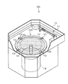
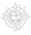
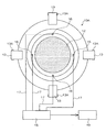
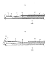
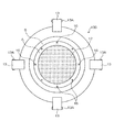
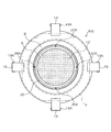
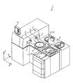
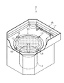
以下、添付図面に従って本発明に係るスピンナ洗浄装置及びスピンナ洗浄方法の好ましい実施の形態について詳説する。まず第1の実施の形態によるスピンナ洗浄装置の構成について説明する。図1は第1の実施の形態によるスピンナ洗浄装置の構成を示した斜視図、図2はスピンナテーブルの上面図、図3は検出部からの配管を示した構成図、図4はスピンナテーブルの側面図である。 Hereinafter, preferred embodiments of a spinner cleaning apparatus and a spinner cleaning method according to the present invention will be described in detail with reference to the accompanying drawings. First, the configuration of the spinner cleaning apparatus according to the first embodiment will be described. FIG. 1 is a perspective view showing the configuration of the spinner cleaning apparatus according to the first embodiment, FIG. 2 is a top view of the spinner table, FIG. 3 is a configuration diagram showing piping from a detection unit, and FIG. It is a side view.
図1に示すスピンナ洗浄装置6Aは、図9に示すダイシング装置1に取り付けられている。ダイシング装置1には、スピンナ洗浄装置6Aの他に、先端にブレード2とホイールカバー(不図示)が取り付けられたスピンドル3、3、撮像手段(不図示)、チャックテーブル4、ロードポート7、搬送手段8、表示手段9、コントローラ(不図示)等とから構成されている。
The
スピンナ洗浄装置6Aは図1に示すように、フレームFにマウントされたウェーハWが吸着されるスピンナテーブル10Aと、揺動するとともに洗浄液を噴射するノズル11を備えている。スピンナテーブル10Aの中央部にはポーラス等により形成されるウェーハ吸着面12が設けられ、外周部にはフレームFを固定する為のフック13が複数設けられている。スピンナテーブル10Aの下部にはスピンナテーブルを回転させる回転手段14が設けられ、スピンナテーブル10Aの周囲には洗浄液を受ける槽15が備えられている。
As shown in FIG. 1, the
図2に示すように、スピンナテーブル10A中央部に形成されたウェーハ吸着面12の外側には、穴形状の吸着確認部16が90度毎に配置されるように複数形成されている。吸着確認部16は、ウェーハ吸着面12と同じ平面上の金属部分である平面部Aに形成されているのが望ましく、平面部Aよりも外側の傾斜部Bに形成されていても良い。
As shown in FIG. 2, a plurality of hole-shaped
フレームFにテープTによりマウントされたウェーハWはウェーハ吸着面12にテープごと吸着され、ウェーハWとフレームFとの間のテープTは吸着確認部16に吸着される。テープTがウェーハ吸着面12と吸着確認部16に吸着された後、フック13が不図示の駆動手段により軸13Aを中心に回転してフレームFがスピンナテーブル10Aに押し付けられて固定される。
The wafer W mounted on the frame F with the tape T is sucked together with the tape on the
スピンナテーブル10Aに形成された吸着確認部16、16・・は、図3に示すように、スピンナテーブル10A内の穴やチューブにより構成される流路17、17・・によりそれぞれ検出部18へ接続されている。なお、各吸着確認部16は個別に検出部18へ接続されるのではなく、1つの流路にまとめられてから一括で検出部18に接続されていてもよい。
As shown in FIG. 3, the
検出部18は、コンプレッサーやエジェクターなどの不図示の真空吸引手段と接続され、流路17を通して各吸着確認部16を真空状態にするとともに、吸着確認部16の圧力変化を検知する不図示の圧力計を備えている。検出部18に備えられた圧力計は、ダイシング装置1に備えられたコントローラ19と接続され、吸着確認部16の圧力の変化に応じてダイシング装置1へ各種の指令を発する。
The
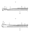
このように構成されたダイシング装置1のスピンナ洗浄装置6Aでは、図4(a)に示すように、フレームFが正しい位置に搬送されてフック13により確実に固定されている場合、吸着確認部16によりテープTが吸着されることで吸着確認部16の圧力が下がり、検出部18で圧力の変化が検知される。これにより、フレームFが正しい位置にあると検出部18またはコントローラ19において判断され、スピンナテーブル10Aが回転してスピンナ洗浄が開始される。
In the
図4(b)に示すように、フレームFが正しい位置に搬送されず、フック13がフレームFを確実に固定していないような場合は、吸着確認部16によりテープTが吸着されない為、吸着確認部16の圧力が下がらず真空状態とならない。これにより、圧力の変化が検出部18で検知されず、フレームFの位置に異常があると検出部18またはコントローラ19において判断され、スピンナテーブル10Aの回転が行われない。
As shown in FIG. 4B, when the frame F is not transported to the correct position and the
これらにより、フレームFが正しい位置に搬送されず突起などに乗りあがりテープTが僅かに浮いているような場合であっても、ウェーハ吸着面12の外側に設けられた吸着確認部16の圧力の変化を検知することでフレームFの異常を検知し、安全にスピンナ洗浄を実行することが可能となる。
As a result, even when the frame F is not conveyed to the correct position and rides on the protrusion and the tape T is slightly lifted, the pressure of the
なお、吸着確認部16は図2に示すように90度毎に4箇所配置されているだけに限らず、図5に示すスピンナテーブル10Bのように8箇所、またはそれ以上でも良く、均等に配置されていればいずれの数でも良い。
The
また、検出部18では、各吸着確認部16の圧力の変化を個別に検知することで、圧力の変化のある吸着確認部16と変化の無い吸着確認部16の位置からいずれの方向でフレームFが異常な位置にあるのかを検出することも可能である。これにより、コントローラ19はダイシング装置1にフレームFの異常位置を知らせ、備えられた搬送手段8によりフレームFの搬送位置を修正する。
In addition, the
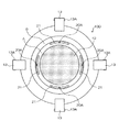
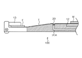
次に本発明に係る第2の実施の形態によるスピンナ洗浄装置について説明する。図6は第2の実施の形態によるスピンナテーブルの上面図、図7は第2の実施の形態によるスピンナテーブルの別の形状を示した上面図。図8はスピンナテーブルの側面図である。 Next, a spinner cleaning apparatus according to a second embodiment of the present invention will be described. FIG. 6 is a top view of a spinner table according to the second embodiment, and FIG. 7 is a top view showing another shape of the spinner table according to the second embodiment. FIG. 8 is a side view of the spinner table.
図6に示すように、スピンナテーブル10C中央部に形成されたウェーハ吸着面12の外側には、溝形状の吸着確認部20がウェーハ吸着面12の外周に沿って形成されている。吸着確認部20は、ウェーハ吸着面12と同じ平面上の金属部分である平面部Aに形成されているのが望ましく、平面部Aよりも外側の傾斜部Bに形成されていても良い。
As shown in FIG. 6, a groove-shaped
フレームFにテープTによりマウントされたウェーハWはウェーハ吸着面12にテープごと吸着され、ウェーハWとフレームFとの間のテープTは吸着確認部20に吸着される。テープTがウェーハ吸着面12と吸着確認部20に吸着された後、フック13が不図示の駆動手段により軸13Aを中心に回転してフレームFがスピンナテーブル10Cに押し付けられて固定される。
The wafer W mounted on the frame F with the tape T is sucked together with the tape on the
吸着確認部20は、溝形状の吸着確認部20の底面に形成された流路20Aと、流路20Aに続く不図示のチューブにより、図3に示される検出部18へ接続されている。検出部18は、吸着確認部20を真空状態にするとともに、吸着確認部20の圧力変化を検知する。検出部18に備えられた圧力計は、ダイシング装置1に備えられたコントローラ19と接続され、吸着確認部20の圧力の変化に応じてダイシング装置1へ各種の指令を発する。
The
このように構成されたスピンナテーブル10Cは、スピンナテーブル10Aと同様に、フレームFが正しい位置に搬送されてフック13により確実に固定されている場合、吸着確認部20によりテープTが吸着されることで吸着確認部20の圧力が下がり、検出部18で圧力の変化が検知される。これにより、フレームFが正しい位置にあると検出部18またはコントローラ19において判断され、スピンナテーブル10Aが回転してスピンナ洗浄が開始される。
Similarly to the spinner table 10A, the spinner table 10C configured as described above allows the tape T to be adsorbed by the
フレームFが正しい位置に搬送されず、フック13がフレームFを確実に固定していないような場合は、吸着確認部20によりテープTが吸着されない為、吸着確認部20の圧力が変化せず検出部で検知されない。これにより、フレームFの位置に異常があると検出部18またはコントローラ19において判断され、スピンナテーブル10Cの回転が行われない。
When the frame F is not conveyed to the correct position and the
これらにより、フレームFが正しい位置に搬送されず突起などに乗りあがりテープTが僅かに浮いているような場合であっても、ウェーハ吸着面12の外周に沿って形成された吸着確認部20の圧力の変化を検知することでフレームFの異常を検知し、安全にスピンナ洗浄を実行することが可能となる。
As a result, even if the frame F is not conveyed to the correct position and rides on a protrusion or the like and the tape T is slightly lifted, the
なお、吸着確認部20は図6に示すように、ウェーハ吸着面12の外周に沿って連続して形成されているだけに限らず、図7に示すスピンナテーブル10Dのように、ウェーハ吸着面12の外周に沿って形成される複数の溝形状である吸着確認部21のような形状であっても良い。
As shown in FIG. 6, the
また、図8に示すように、ウェーハWとフレームFとの間の撓んだテープTが、吸着確認部20で吸着吸引されることにより、吸着確認部20に向かってテープTが突出される。これにより、吸着確認部20はウェーハ吸着面12外側に配置されているので、突出したテープTが壁となり、テープTとスピンナテーブル10Cの間を伝ってウェーハ吸着面12へ洗浄液が進入することが防止される。これにより、ポーラス等により形成されたウェーハ吸着面12の汚れが軽減され、ウェーハWの吸着を確実にする。
Further, as shown in FIG. 8, the tape T that is bent between the wafer W and the frame F is sucked and sucked by the
次に、本発明に係るスピンナ洗浄方法について詳説する。 Next, the spinner cleaning method according to the present invention will be described in detail.
図1に示すスピンナ洗浄装置6Aは、スピンナテーブル10Aと、テープTによりウェーハWがマウントされるフレームFを固定するフック13と、洗浄液を噴射するノズル11と、図3に示す検出部18が備えられている。スピンナテーブル10Aには、中央部にポーラス等により形成されるウェーハ吸着面12が設けられ、ウェーハ吸着面12の外側には吸着確認部16が設けられ、スピンナテーブル10Aの外周部にフック13が設けられている。
A
ウェーハWをスピンナ洗浄する際には、テープTによりフレームFにマウントされたウェーハWが、フレームFごとスピンナテーブル10A上に図9に示す搬送手段8により搬送され、ウェーハ吸着面12で吸着固定される。ウェーハWとフレームFとの間のテープT部分はウェーハ吸着面12よりも外側となる吸着確認部16により吸着される。吸着後、フレームFがフック13により固定される。
When the wafer W is subjected to spinner cleaning, the wafer W mounted on the frame F with the tape T is transported together with the frame F onto the spinner table 10A by the transport means 8 shown in FIG. The The portion of the tape T between the wafer W and the frame F is sucked by the
続いて、ウェーハ吸着面12の外側に設けられた吸着確認部16に生じる圧力が検出部18により検出される。
Subsequently, the pressure generated in the
テープTが正しく吸着確認部16に吸着され、吸着確認部16の圧力が下がりフレームFの位置に異常がないと判断された場合はスピンナテーブル10Aが回転手段14により回転されてスピンナ洗浄が開始される。吸着確認部16でテープが吸着されず圧力が変化しない場合は、フレームFの位置が異常であるとしてスピンナテーブル10Aの回転が行われない。
When the tape T is correctly adsorbed by the adsorbing
これにより、フレームFが正しい位置に搬送されず突起などに乗りあがりテープTが僅かに浮いているような場合であっても、ウェーハ吸着面12の外側に設けられた吸着確認部16の圧力の変化を検知することでフレームFの異常を検知し、安全にスピンナ洗浄を実行することが出来る。
As a result, even when the frame F is not conveyed to the correct position and rides on the protrusion or the like and the tape T slightly floats, the pressure of the
以上、説明したように、本発明に係わるスピンナ洗浄装置及びスピンナ洗浄方法によれば、フレームの位置の不具合を正確に検知し、フックが確実にフレームを固定していない状態のままでのスピンナテーブルの回転を未然に防ぎ、安全にスピンナ洗浄を実行することを可能にする。 As described above, according to the spinner cleaning device and the spinner cleaning method according to the present invention, the spinner table that accurately detects a defect in the position of the frame and does not securely fix the frame to the hook. It is possible to prevent spin rotation and to safely perform spinner cleaning.
また、各吸着確認部の圧力の変化を個別に検知することで、いずれの方向でフレームが異常な位置にあるのかを検出することも可能である。 It is also possible to detect in which direction the frame is in an abnormal position by individually detecting a change in pressure of each adsorption confirmation unit.
更には、ウェーハとフレームとの間の撓んだテープが、吸着確認部で吸着吸引されることにより、突出したテープが壁となり、テープとスピンナテーブルの間を伝ってウェーハ吸着面へ洗浄液が進入することが防止されるので、ポーラス等により形成されたウェーハ吸着面の汚れを軽減することも可能となる。 Furthermore, the tape that has been bent between the wafer and the frame is sucked and sucked by the suction check unit, so that the protruding tape becomes a wall, and the cleaning liquid enters the wafer suction surface between the tape and the spinner table. Therefore, it is possible to reduce the contamination of the wafer suction surface formed by porous or the like.
1…ダイシング装置,2…ブレード,3…スピンドル,4…チャックテーブル,5…加工部,6、6A…スピンナ洗浄装置,7…ロードポート,8…搬送手段,9…表示手段,10A、10B、10C、10D…スピンナテーブル,12…ウェーハ吸着面,13…フック,13A…軸,14…回転手段,15…槽,16、20、21…吸着確認部,17、20A…流路,18…検出部,19…コントローラ
DESCRIPTION OF SYMBOLS 1 ... Dicing apparatus, 2 ... Blade, 3 ... Spindle, 4 ... Chuck table, 5 ... Processing part, 6, 6A ... Spinner washing | cleaning apparatus, 7 ... Load port, 8 ... Conveyance means, 9 ... Display means, 10A, 10B, DESCRIPTION OF
Claims (6)
前記吸着確認部に生じる圧力を検出する検出部と、
揺動しながら前記スピンナテーブル上のウェーハへ向けて洗浄水を噴射するノズルと、
前記スピンナテーブルの外周部に設けられた前記フレームを固定する複数のフックと、
前記スピンナテーブルを回転させる回転手段と、
を備えたことを特徴とするスピンナ洗浄装置。 A wafer suction surface is provided in the center portion, a suction confirmation portion is provided outside the wafer suction surface, and a spinner table for fixing the wafer mounted on the frame by a tape on the wafer suction surface,
A detection unit for detecting pressure generated in the adsorption confirmation unit;
A nozzle that sprays cleaning water toward the wafer on the spinner table while swinging;
A plurality of hooks for fixing the frame provided on the outer periphery of the spinner table;
A rotating means for rotating the spinner table;
A spinner cleaning apparatus comprising:
前記吸着確認部に生じる圧力を前記検出部で検出することにより前記吸着確認部における前記テープの吸着状況を検知し、前記吸着確認部における前記テープの吸着状況より前記フックによる前記フレームの固定状況を検知した後、前記回転手段により前記スピンナテーブルを回転させるとともに前記ノズルより洗浄液を噴射することで前記ウェーハの洗浄を行なうことを特徴とするスピンナ洗浄方法。 A wafer suction surface is provided in the center, a suction confirmation unit is provided outside the wafer suction surface, and a spinner table that suctions and fixes a wafer mounted on a frame with a tape on the wafer suction surface, and the suction confirmation unit A detection unit for detecting the generated pressure, a nozzle for spraying cleaning water toward the wafer on the spinner table while swinging, and a plurality of hooks for fixing the frame provided on the outer periphery of the spinner table, In a spinner cleaning method using a spinner cleaning apparatus provided with a rotating means for rotating the spinner table,
By detecting the pressure generated in the suction confirmation unit by the detection unit, the suction state of the tape in the suction confirmation unit is detected, and the fixing state of the frame by the hook is determined from the suction state of the tape in the suction confirmation unit. After the detection, the spinner cleaning method is characterized in that the spinner table is rotated by the rotating means and the wafer is cleaned by spraying a cleaning liquid from the nozzle.
Priority Applications (1)
| Application Number | Priority Date | Filing Date | Title |
|---|---|---|---|
| JP2010231543A JP5673929B2 (en) | 2010-10-14 | 2010-10-14 | Spinner cleaning apparatus and spinner cleaning method |
Applications Claiming Priority (1)
| Application Number | Priority Date | Filing Date | Title |
|---|---|---|---|
| JP2010231543A JP5673929B2 (en) | 2010-10-14 | 2010-10-14 | Spinner cleaning apparatus and spinner cleaning method |
Publications (2)
| Publication Number | Publication Date |
|---|---|
| JP2012084792A true JP2012084792A (en) | 2012-04-26 |
| JP5673929B2 JP5673929B2 (en) | 2015-02-18 |
Family
ID=46243340
Family Applications (1)
| Application Number | Title | Priority Date | Filing Date |
|---|---|---|---|
| JP2010231543A Active JP5673929B2 (en) | 2010-10-14 | 2010-10-14 | Spinner cleaning apparatus and spinner cleaning method |
Country Status (1)
| Country | Link |
|---|---|
| JP (1) | JP5673929B2 (en) |
Cited By (6)
| Publication number | Priority date | Publication date | Assignee | Title |
|---|---|---|---|---|
| JP2015109381A (en) * | 2013-12-05 | 2015-06-11 | 株式会社ディスコ | Cleaning device and cutting device |
| KR101573155B1 (en) | 2011-06-15 | 2015-12-01 | 도오꾜오까고오교 가부시끼가이샤 | Retention device and retention method |
| JP2017216291A (en) * | 2016-05-30 | 2017-12-07 | 株式会社ディスコ | Protective film formation device |
| KR20190083620A (en) * | 2018-01-04 | 2019-07-12 | 가부시기가이샤 디스코 | Machining apparatus |
| CN115424972A (en) * | 2022-11-03 | 2022-12-02 | 智程半导体设备科技(昆山)有限公司 | Etching device for carrying out temperature compensation on back of wafer |
| US20230178397A1 (en) * | 2021-12-06 | 2023-06-08 | Skyworks Solutions, Inc. | Wafer cleaning with wafer assembly presence detection |
Citations (3)
| Publication number | Priority date | Publication date | Assignee | Title |
|---|---|---|---|---|
| JP2007299863A (en) * | 2006-04-28 | 2007-11-15 | Disco Abrasive Syst Ltd | Laser processing apparatus and method for removing wafer from chuck table |
| JP2008085146A (en) * | 2006-09-28 | 2008-04-10 | Disco Abrasive Syst Ltd | Rotary table and cleaning equipment |
| JP2009065108A (en) * | 2007-08-14 | 2009-03-26 | Tokyo Seimitsu Co Ltd | Wafer table, surface protective film peeling apparatus and surface protective film peeling method |
-
2010
- 2010-10-14 JP JP2010231543A patent/JP5673929B2/en active Active
Patent Citations (3)
| Publication number | Priority date | Publication date | Assignee | Title |
|---|---|---|---|---|
| JP2007299863A (en) * | 2006-04-28 | 2007-11-15 | Disco Abrasive Syst Ltd | Laser processing apparatus and method for removing wafer from chuck table |
| JP2008085146A (en) * | 2006-09-28 | 2008-04-10 | Disco Abrasive Syst Ltd | Rotary table and cleaning equipment |
| JP2009065108A (en) * | 2007-08-14 | 2009-03-26 | Tokyo Seimitsu Co Ltd | Wafer table, surface protective film peeling apparatus and surface protective film peeling method |
Cited By (10)
| Publication number | Priority date | Publication date | Assignee | Title |
|---|---|---|---|---|
| KR101573155B1 (en) | 2011-06-15 | 2015-12-01 | 도오꾜오까고오교 가부시끼가이샤 | Retention device and retention method |
| US9406542B2 (en) | 2011-06-15 | 2016-08-02 | Tokyo Ohka Kogyo Co., Ltd. | Retention device and retention method |
| JP2015109381A (en) * | 2013-12-05 | 2015-06-11 | 株式会社ディスコ | Cleaning device and cutting device |
| JP2017216291A (en) * | 2016-05-30 | 2017-12-07 | 株式会社ディスコ | Protective film formation device |
| KR20190083620A (en) * | 2018-01-04 | 2019-07-12 | 가부시기가이샤 디스코 | Machining apparatus |
| JP2019121675A (en) * | 2018-01-04 | 2019-07-22 | 株式会社ディスコ | Processing device |
| JP7057673B2 (en) | 2018-01-04 | 2022-04-20 | 株式会社ディスコ | Processing equipment |
| KR102659790B1 (en) | 2018-01-04 | 2024-04-22 | 가부시기가이샤 디스코 | Machining apparatus |
| US20230178397A1 (en) * | 2021-12-06 | 2023-06-08 | Skyworks Solutions, Inc. | Wafer cleaning with wafer assembly presence detection |
| CN115424972A (en) * | 2022-11-03 | 2022-12-02 | 智程半导体设备科技(昆山)有限公司 | Etching device for carrying out temperature compensation on back of wafer |
Also Published As
| Publication number | Publication date |
|---|---|
| JP5673929B2 (en) | 2015-02-18 |
Similar Documents
| Publication | Publication Date | Title |
|---|---|---|
| JP5673929B2 (en) | Spinner cleaning apparatus and spinner cleaning method | |
| JP6546343B2 (en) | Dressing apparatus and wafer polishing apparatus including the same | |
| US8997821B2 (en) | Delamination system | |
| JP5478586B2 (en) | Cleaning device, peeling system, cleaning method, program, and computer storage medium | |
| TWI512876B (en) | Stripping device, stripping system, stripping method and non-transitory computer readable memory media | |
| TWI746763B (en) | Substrate processing device, substrate processing method and storage medium | |
| JP5726686B2 (en) | Liquid processing apparatus and method for controlling liquid processing apparatus | |
| US20160074988A1 (en) | Processing module, processing apparatus, and processing method | |
| JP6568773B2 (en) | Substrate transfer device and peeling system | |
| KR102851724B1 (en) | Cleaning apparatus | |
| JP7229353B2 (en) | Separation device and separation method | |
| JP2020115513A (en) | Substrate processing method and substrate processing apparatus | |
| KR102394673B1 (en) | Cutting blade, mount flange | |
| WO2012026148A1 (en) | Separation system, separation method, program and computer storage medium | |
| JP6397270B2 (en) | Cutting equipment | |
| CN111341694A (en) | Wafer manufacturing equipment | |
| JP7308265B2 (en) | Separation device and separation method | |
| JP2017069336A (en) | Substrate processing apparatus, cleaning method for suction holding unit, and storage medium | |
| JP2006054388A (en) | Workpiece conveying device, spinner cleaning device, grinding device, workpiece conveying method | |
| JP6366431B2 (en) | Grinding equipment | |
| JP2011066198A (en) | Grinding processing device | |
| JP5048987B2 (en) | Cleaning device | |
| KR20070118205A (en) | Chuck Structure of Wafer Cleaning Device | |
| JP4963411B2 (en) | Manufacturing method of semiconductor device or semiconductor wafer | |
| JP5970102B2 (en) | Liquid processing equipment |
Legal Events
| Date | Code | Title | Description |
|---|---|---|---|
| A621 | Written request for application examination |
Free format text: JAPANESE INTERMEDIATE CODE: A621 Effective date: 20131001 |
|
| A977 | Report on retrieval |
Free format text: JAPANESE INTERMEDIATE CODE: A971007 Effective date: 20140722 |
|
| A131 | Notification of reasons for refusal |
Free format text: JAPANESE INTERMEDIATE CODE: A131 Effective date: 20140724 |
|
| A521 | Request for written amendment filed |
Free format text: JAPANESE INTERMEDIATE CODE: A523 Effective date: 20140922 |
|
| A131 | Notification of reasons for refusal |
Free format text: JAPANESE INTERMEDIATE CODE: A131 Effective date: 20141023 |
|
| A521 | Request for written amendment filed |
Free format text: JAPANESE INTERMEDIATE CODE: A523 Effective date: 20141110 |
|
| TRDD | Decision of grant or rejection written | ||
| A01 | Written decision to grant a patent or to grant a registration (utility model) |
Free format text: JAPANESE INTERMEDIATE CODE: A01 Effective date: 20141203 |
|
| A61 | First payment of annual fees (during grant procedure) |
Free format text: JAPANESE INTERMEDIATE CODE: A61 Effective date: 20141216 |
|
| R150 | Certificate of patent or registration of utility model |
Ref document number: 5673929 Country of ref document: JP Free format text: JAPANESE INTERMEDIATE CODE: R150 |
|
| R250 | Receipt of annual fees |
Free format text: JAPANESE INTERMEDIATE CODE: R250 |
|
| R250 | Receipt of annual fees |
Free format text: JAPANESE INTERMEDIATE CODE: R250 |
|
| R250 | Receipt of annual fees |
Free format text: JAPANESE INTERMEDIATE CODE: R250 |
|
| R250 | Receipt of annual fees |
Free format text: JAPANESE INTERMEDIATE CODE: R250 |
|
| R250 | Receipt of annual fees |
Free format text: JAPANESE INTERMEDIATE CODE: R250 |
|
| R250 | Receipt of annual fees |
Free format text: JAPANESE INTERMEDIATE CODE: R250 |
|
| R250 | Receipt of annual fees |
Free format text: JAPANESE INTERMEDIATE CODE: R250 |
|
| R250 | Receipt of annual fees |
Free format text: JAPANESE INTERMEDIATE CODE: R250 |
|
| R250 | Receipt of annual fees |
Free format text: JAPANESE INTERMEDIATE CODE: R250 |